EP4002064A1 - Procédé et système permettant d'afficher un curseur pour l'interaction de l'utilisateur sur un dispositif d'affichage - Google Patents
Procédé et système permettant d'afficher un curseur pour l'interaction de l'utilisateur sur un dispositif d'affichage Download PDFInfo
- Publication number
- EP4002064A1 EP4002064A1 EP20208500.7A EP20208500A EP4002064A1 EP 4002064 A1 EP4002064 A1 EP 4002064A1 EP 20208500 A EP20208500 A EP 20208500A EP 4002064 A1 EP4002064 A1 EP 4002064A1
- Authority
- EP
- European Patent Office
- Prior art keywords
- target position
- target
- reference position
- modified
- determining
- Prior art date
- Legal status (The legal status is an assumption and is not a legal conclusion. Google has not performed a legal analysis and makes no representation as to the accuracy of the status listed.)
- Withdrawn
Links
Images


Classifications
-
- G—PHYSICS
- G06—COMPUTING; CALCULATING OR COUNTING
- G06F—ELECTRIC DIGITAL DATA PROCESSING
- G06F3/00—Input arrangements for transferring data to be processed into a form capable of being handled by the computer; Output arrangements for transferring data from processing unit to output unit, e.g. interface arrangements
- G06F3/01—Input arrangements or combined input and output arrangements for interaction between user and computer
- G06F3/017—Gesture based interaction, e.g. based on a set of recognized hand gestures
Definitions
- the present disclosure generally relates to interactions in extended reality (XR), in particular, to a method and a system for showing a current position for user interaction on a display device in the XR.
- XR extended reality
- Extended reality (XR) technologies for simulating senses, perception, and/or environment such as virtual reality (VR), augmented reality (AR) and mixed reality (MR), are popular nowadays.
- the aforementioned technologies can be applied in multiple fields, such as gaming, military training, healthcare, remote working, etc.
- XR a user may interact with one or more objects and/or the environment.
- the user may use his/her hands or a controller to change the field of view in the environment or to select a target object.
- the accuracy for showing a cursor for user interaction on a display device pointed by the user on the target object may be influenced by the swinging or shaking of the human body of the user or other factors. If the sensitivity for tracking the hands of the user or the controller is too high, the cursor may drift frequently because of the unsteadiness of the hands. On the other hand, if the sensitivity for tracking the hands of the user or the controller is too low, the cursor may be too slow for responding and inaccurated in most of time.
- the present disclosure is directed to a method and a system for showing a cursor for user interaction on a display device, to make the position of the cursor steady.
- a method for showing a cursor for user interaction on a display device includes, but is not limited to, the following steps.
- a reference position is determined.
- the reference position is initialized at the end of a ray cast emitted from the user side.
- a target position is determined.
- the target position is moved with the human body portion of the user.
- the target position is different from the reference position.
- a modified position is determined based on the reference position and the target position, where the reference position, the target position, and the modified position are located on the same plane parallel with the user side.
- the modified position is different from the target position.
- the modified position is used as the current position of the cursor, where the modified position represents the position of the end of the ray cast emitted from the user side currently.
- a system for showing a current position for user interaction on a display device includes, but is not limited to, a motion sensor, a memory, and a processor.
- the motion sensor is used for detecting the motion of a human body portion of a user.
- the memory is used for storing program code.
- the processor is coupled to the motion sensor and the memory and loading the program code to perform the following steps.
- a reference position is determined.
- the reference position is initialized at the end of a ray cast emitted from the user side.
- a target position is determined.
- the target position is moved with the human body portion of the user.
- the target position is different from the reference position.
- a modified position is determined based on the reference position and the target position, where the reference position, the target position, and the modified position are located on the same plane parallel with the user side.
- the modified position is different from the target position.
- the modified position is used as the current position of the cursor, where the modified position represents the position of the end of the ray cast emitted from the user side currently.
- the reference position would also be used as a reference to determine the positions of the cursor. Accordingly, the cursor would be steady and has a quick response for the motion of the human body portion.
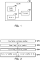
- FIG. 1 is a block diagram illustrating a system 100 for showing a cursor for user interaction on a display device according to one of the exemplary embodiments of the disclosure.
- the system 100 includes, but not limited to, one or more motion sensors 110, a memory 130, and a processor 150.
- the system 100 is adapted for XR, or other reality simulation related technology.
- the motion sensor 110 may be an accelerometer, a gyroscope, a magnetometer, a laser sensor, an inertial measurement unit (IMU), an infrared ray (IR) sensor, an image sensor, a depth camera, or any combination of aforementioned sensors.
- the motion sensor 130 is used for sensing the motion of a user's human body portion (e.g., fingers, hands, legs, or arms), to generate motion sensing data sensed by the motion sensor 110 (e.g. camera images, sensed strength values, etc.).
- the motion-sensing data comprises a 3-degree of freedom (3-DoF) data
- the 3-DoF data is related to the rotation data of the user's hand in three-dimensional (3D) space, such as accelerations in yaw, roll, and pitch.
- the motion-sensing data comprises a 6-degree of freedom (6-DoF) data. Comparing with the 3-DoF data, the 6-DoF data is further related to the displacement of the user's hand in three perpendicular axes, such as accelerations in surge, heave, and sway.
- the motion-sensing data comprises a relative position and/or displacement of the user's leg in the 2D/3D space.
- the motion sensor 130 could be embedded in a handheld controller or a wearable apparatus acted with the user's human body portion, such as glasses, an HMD, or the likes.
- the memory 130 may be any type of a fixed or movable random-access memory (RAM), a read-only memory (ROM), a flash memory, a similar device, or a combination of the above devices.
- RAM random-access memory
- ROM read-only memory
- flash memory a similar device, or a combination of the above devices.
- the memory 130 records program codes, device configurations, buffer data, or permanent data (such as motion sensing data, positions, tolerance area, spacing, or weighted relation), and these data would be introduced later.
- the processor 150 is coupled to the motion sensor 110 and the memory 130.
- the processor 150 is configured to load the program codes stored in the memory 130, to perform a procedure of the exemplary embodiment of the disclosure.
- the processor 150 may be a central processing unit (CPU), a microprocessor, a microcontroller, a graphics processing unit (GPU), a digital signal processing (DSP) chip, a field-programmable gate array (FPGA).
- CPU central processing unit
- microprocessor a microcontroller
- GPU graphics processing unit
- DSP digital signal processing
- FPGA field-programmable gate array
- the functions of the processor 150 may also be implemented by an independent electronic device or an integrated circuit (IC), and operations of the processor 150 may also be implemented by software.
- IC integrated circuit
- an HMD or digital glasses i.e., a display device
- the motion sensor 110 includes the motion sensor 110, the memory 130, and the processor 150.
- the processor 150 may not be disposed at the same apparatus with the motion sensor 110.
- the apparatuses respectively equipped with the motion sensor 110 and the processor 150 may further include communication transceivers with compatible communication technology, such as Bluetooth, Wi-Fi, and IR wireless communications, or physical transmission line, to transmit or receive data with each other.
- the processor 150 may be disposed in an HMD while the motion sensor 110 is disposed at a controller outside the HMD.
- the processor 150 may be disposed in a computing device while the motion sensor 110 being disposed outside the computing device.
- the system 100 further includes a display usch as LCD, LED display, or OLED display.
- FIG. 2 is a flowchart illustrating a method for showing a current position for user interaction on a display device according to one of the exemplary embodiments of the disclosure.
- the processor 150 may determine a reference position (step S210). Specifically, the reference position is initialized at the end of a ray cast emitted from the user side.
- the user may use his human body portion (such as finger, hand, head, or leg) or the controller held by the human body portion to aim at a target object in the XR.
- the processor 150 may determine the position of the human body portion or the position of the controller in the 3D space based on the motion of the human body portion of the user detected by the motion sensor 110.
- a ray cast would be formed and emitted from the user side, such as the user's body portion, the user's eye, the motion sensor 110, or a portion of the HMD.
- the ray cast may pass through the human body portion or the controller and further extend along with a straight line or a curve. If the ray cast collides with any object which are allowed to be pointed by the user in the XR, a target point would be located at the end of the ray cast where the end of the ray cast is located on the collided object.
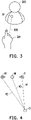
- FIG. 3 is a schematic diagram illustrating the generation of the target point according to one of the exemplary embodiments of the disclosure.
- the one index finger up gesture of the user's hand 301 is conformed to the predefined gesture for aiming object, and the ray cast 305 emitted from the user's eye via the user's hand 301 is generated.
- a target point TP would be located at the end of the ray cast 305, and a cursor would be presented on the display based on the target point TP. If the user moves his/her hand 301, the target point TP and the cursor also correspondingly move.
- the processor 150 may record the initial position of the target point as the reference position in the XR at an initial time point.
- the form of the position may be the coordinates in three axes or a relative relation of other objects. If the target point does not move for a time duration (for example, 1 second, 3 seconds, or 5 seconds), the processor 150 may use the reference position to represent the current position of the cursor or the position of the end of the ray cast.
- the processor 150 may determine a target position (step S230). Specifically, the human body portion may shake or swing, so the position of the target point may move out of the reference position at a subsequent time point after the initial time point. In this embodiment, if the target point is not located at the reference position, the position of the target point would be called as the target position. That is, the target position is different from the reference position.
- the target position would move with the human body portion or the controller hold by the human body portion. For example, the hand of the user moves from the center to the right side, and the target position would also move from the center to the right side.
- the processor 150 may determine a modified position based on the reference position and the target position (step S250). Specifically, in the conventional approaches, the current position of the cursor located at the end of the ray cast would be determined as the target position of the target point. However, the current position of the cursor merely based on the motion of the human body portion may not be steady. In this embodiment, the current position of the cursor would not be the target position of the target point.
- the reference position, the target position, and the modified position are all located on the same plane parallel with the user side, and the modified position is different from the target position.
- the processor 150 may determine the modified position based on a weighted relation of the target position and the reference position. Specifically, the sum of weights of the target position and the reference position is one, and the weight of the target position is not one. For example, if the weight of the target position (located at coordinates (0,0)) is 0.3 and the weight of the reference position (located at coordinates (10, 10)) is 0.7, the modified position would be located at coordinates (7, 7). That is, the weighted calculated result (i.e., the weighted relation) of the target position and the reference position with corresponding weights is the modified position.
- the weighted calculated result i.e., the weighted relation
- FIG. 4 is a top view schematic diagram illustrating vectors V1, V2, and V3 according to one of the exemplary embodiments of the disclosure.
- a first vector V1 is formed from an original position O of the original point to the reference position R
- a second vector V2 is formed from the original position O to the target position A1.
- the processor 150 may determine a third vector V3 formed from the original position O to the modified position M of the target point based on the first vector V1, the second vector V2, and the weighted relation of the first vector V1 and the second vector V2.
- the target position A1, the modified position M, and the reference position R are located on the same plane. That is, a straight line, which is connected between the target position A1 and the reference position R, would also pass through the modified position M.
- the weights of the current position and the reference position in the weighted relation vary based on the accuracy requirement of the current position.
- the accuracy requirement may be adapted for typing a keyboard, the weight ⁇ may be larger than the weight ⁇ .
- the accuracy requirement may be adapted for grasping a large object in the XR, the weight ⁇ may be larger than the weight ⁇ . That is, the higher the accuracy requirement is, the larger the weight ⁇ is. The lower the accuracy requirement is, the larger the weight ⁇ is.
- FIG. 5 is a flowchart illustrating the determination of the second position according to one of the exemplary embodiments of the disclosure.
- the processor 150 may determine a tolerance area based on the initial position of the reference position (step S510).
- the tolerance area may be a circle, a square, or other shapes radiated from the reference position.
- FIG. 6 is a schematic diagram illustrating a tolerance area TA according to one of the exemplary embodiments of the disclosure. Referring to FIG. 6 , the tolerance area TA is a circle with radius S, and the tolerance area TA is radiated from the reference position P0 of the target point.
- the processor 150 may determine whether the target position of the target point is located within the tolerance area (step S530). For example, the processor 150 may determine whether the coordinates of the target position is overlapped with the tolerance area. For another example, the processor 150 may calculate the distance between the target position and the reference position and the distance between the edge of the tolerance area and the reference position, and determine which distance is larger than the other.
- FIG. 7 is an example illustrating that the current position is located within the tolerance area TA.
- the target positions A2 and A3 are both located within the tolerance area TA where the radius S is larger than the distance from the reference position P0 to the current position A2 or A3.
- the processor 150 may make the reference position fixed if the target position of the target point is located within the tolerance area (step S550).
- the tolerance area would be considered as an area that allows part of variations of the current position. These variations of the target position may be caused by the shaking, swinging, or other small-scale motions of the human body portion of the user. If the variations of the target position do not exceed the tolerance area, the processor 150 may consider that the user still intends to point around the reference position. Therefore, the modified position may stay within the tolerance area based on the aforementioned weighted relation.
- the processor 150 may determine the modified as the reference position. For example, the weight ⁇ of the reference position is one, and the weight of the target position is zero. Taking FIG. 7 as an example, the modified position corresponding to the target positions A2 and A3 would be the reference position P0.
- the size and/or the shape of the tolerance area may relate to the accuracy requirement of the current position of the target point, such as the selection of a smaller object or a larger object.
- the target position of the target point is not located within the tolerance area. If the variations of the target position exceed the tolerance area, the processor 150 may consider that the user may not intend to point at the reference position. However, the modified position is still not the target position. Instead, the reference position may move from the initial position, and the displacement and the direction of the motion of the reference position would be the same as the target position. That is, the reference position moves with the target position. When the target position just moves out of the tolerance area, the reference position would be located on a straight line connected to the initial position and the current position. Furthermore, there is a spacing between the current position and the reference position.
- FIG. 8 is an example illustrating that the target position A4 is not located within the tolerance area TA.
- the target position A4 is not located within the tolerance area TA where the radius S is less than the distance from the initial position of the reference position P0 to the target position A4.
- the spacing between the target position and the reference position is the same as a distance between the reference position and the edge of the tolerance area. Taking FIG. 8 as an example, the spacing S2 equals the radius S. In some embodiments, the spacing may be different from the distance between the reference position and the edge of the tolerance area.
- the spacing is fixed. In another embodiment, the spacing varies based on the speed of the motion of the human body portion which triggers the motion of the ray cast. For example, if the speed of the human body portion/ ray cast is faster relative to a speed threshold, the spacing may be enlarged. If the speed is slower, the spacing may be shortened. In some embodiments, the spacing varies based on the distance between the current position and the reference position. For example, the distance between the current position and the reference position is longer relative to a distance threshold, the spacing may be enlarged. If the speed is shorter, the spacing may be shortened.
- the processor 150 may use the modified position as the current position of the cursor (step S270). That is, the modified position, which represents the position of the end of the ray cast currently, is a modification of the target position. Then, the cursor would be shown on the display device at the modified position but not the target position.
- the exemplary embodiments described above depicted the method and the system for showing the cursor for user interaction on the display device.
- the modified position may be determined based on the weighted relation of the reference position and the target position.
- the reference position may move with the target position if the target position is located out of the tolerance area. Accordingly, the current position of the cursor would be steady.
Landscapes
- Engineering & Computer Science (AREA)
- General Engineering & Computer Science (AREA)
- Theoretical Computer Science (AREA)
- Human Computer Interaction (AREA)
- Physics & Mathematics (AREA)
- General Physics & Mathematics (AREA)
- Position Input By Displaying (AREA)
Priority Applications (1)
| Application Number | Priority Date | Filing Date | Title |
|---|---|---|---|
| EP20208500.7A EP4002064A1 (fr) | 2020-11-18 | 2020-11-18 | Procédé et système permettant d'afficher un curseur pour l'interaction de l'utilisateur sur un dispositif d'affichage |
Applications Claiming Priority (1)
| Application Number | Priority Date | Filing Date | Title |
|---|---|---|---|
| EP20208500.7A EP4002064A1 (fr) | 2020-11-18 | 2020-11-18 | Procédé et système permettant d'afficher un curseur pour l'interaction de l'utilisateur sur un dispositif d'affichage |
Publications (1)
| Publication Number | Publication Date |
|---|---|
| EP4002064A1 true EP4002064A1 (fr) | 2022-05-25 |
Family
ID=73476066
Family Applications (1)
| Application Number | Title | Priority Date | Filing Date |
|---|---|---|---|
| EP20208500.7A Withdrawn EP4002064A1 (fr) | 2020-11-18 | 2020-11-18 | Procédé et système permettant d'afficher un curseur pour l'interaction de l'utilisateur sur un dispositif d'affichage |
Country Status (1)
| Country | Link |
|---|---|
| EP (1) | EP4002064A1 (fr) |
Citations (12)
| Publication number | Priority date | Publication date | Assignee | Title |
|---|---|---|---|---|
| US20040041828A1 (en) * | 2002-08-30 | 2004-03-04 | Zellhoefer Jon William | Adaptive non-contact computer user-interface system and method |
| US20050243062A1 (en) * | 2004-04-30 | 2005-11-03 | Hillcrest Communications, Inc. | Free space pointing devices with tilt compensation and improved usability |
| US20060109242A1 (en) * | 2004-11-19 | 2006-05-25 | Simpkins Daniel S | User interface for impaired users |
| US20130321347A1 (en) * | 2011-02-18 | 2013-12-05 | VTouch Co., Ltd. | Virtual touch device without pointer |
| US20140184501A1 (en) * | 2013-01-02 | 2014-07-03 | Samsung Electronics Co., Ltd. | Display apparatus, input apparatus, and method for compensating coordinates using the same |
| US20170038830A1 (en) * | 2015-08-04 | 2017-02-09 | Google Inc. | Context sensitive hand collisions in virtual reality |
| US20170147081A1 (en) * | 2014-08-06 | 2017-05-25 | Starship Vending-Machine Corp. | Method and device for correcting motion information collected by nui device |
| US20180136744A1 (en) * | 2016-11-15 | 2018-05-17 | Google Llc | Input controller stabilization techniques for virtual reality systems |
| US20190228243A1 (en) * | 2018-01-23 | 2019-07-25 | Toyota Research Institute, Inc. | Vehicle systems and methods for determining a target based on a virtual eye position and a pointing direction |
| US20200042170A1 (en) * | 2018-08-01 | 2020-02-06 | International Business Machines Corporation | Compensating for user hand tremors when using hand-held electronic devices |
| US20200226814A1 (en) * | 2019-01-11 | 2020-07-16 | Microsoft Technology Licensing, Llc | Holographic palm raycasting for targeting virtual objects |
| US10802600B1 (en) * | 2019-09-20 | 2020-10-13 | Facebook Technologies, Llc | Virtual interactions at a distance |
-
2020
- 2020-11-18 EP EP20208500.7A patent/EP4002064A1/fr not_active Withdrawn
Patent Citations (12)
| Publication number | Priority date | Publication date | Assignee | Title |
|---|---|---|---|---|
| US20040041828A1 (en) * | 2002-08-30 | 2004-03-04 | Zellhoefer Jon William | Adaptive non-contact computer user-interface system and method |
| US20050243062A1 (en) * | 2004-04-30 | 2005-11-03 | Hillcrest Communications, Inc. | Free space pointing devices with tilt compensation and improved usability |
| US20060109242A1 (en) * | 2004-11-19 | 2006-05-25 | Simpkins Daniel S | User interface for impaired users |
| US20130321347A1 (en) * | 2011-02-18 | 2013-12-05 | VTouch Co., Ltd. | Virtual touch device without pointer |
| US20140184501A1 (en) * | 2013-01-02 | 2014-07-03 | Samsung Electronics Co., Ltd. | Display apparatus, input apparatus, and method for compensating coordinates using the same |
| US20170147081A1 (en) * | 2014-08-06 | 2017-05-25 | Starship Vending-Machine Corp. | Method and device for correcting motion information collected by nui device |
| US20170038830A1 (en) * | 2015-08-04 | 2017-02-09 | Google Inc. | Context sensitive hand collisions in virtual reality |
| US20180136744A1 (en) * | 2016-11-15 | 2018-05-17 | Google Llc | Input controller stabilization techniques for virtual reality systems |
| US20190228243A1 (en) * | 2018-01-23 | 2019-07-25 | Toyota Research Institute, Inc. | Vehicle systems and methods for determining a target based on a virtual eye position and a pointing direction |
| US20200042170A1 (en) * | 2018-08-01 | 2020-02-06 | International Business Machines Corporation | Compensating for user hand tremors when using hand-held electronic devices |
| US20200226814A1 (en) * | 2019-01-11 | 2020-07-16 | Microsoft Technology Licensing, Llc | Holographic palm raycasting for targeting virtual objects |
| US10802600B1 (en) * | 2019-09-20 | 2020-10-13 | Facebook Technologies, Llc | Virtual interactions at a distance |
Similar Documents
| Publication | Publication Date | Title |
|---|---|---|
| CN112783328B (zh) | 提供虚拟空间的方法、提供虚拟体验的方法、程序以及记录介质 | |
| US9928650B2 (en) | Computer program for directing line of sight | |
| CN107407964B (zh) | 存储有用于在沉浸型虚拟空间控制目标操作的计算机程序的存储器以及计算机系统 | |
| US20220137787A1 (en) | Method and system for showing a cursor for user interaction on a display device | |
| US11119570B1 (en) | Method and system of modifying position of cursor | |
| US11442274B2 (en) | Electronic device and method for displaying object associated with external electronic device on basis of position and movement of external electronic device | |
| US10877562B2 (en) | Motion detection system, motion detection method and computer-readable recording medium thereof | |
| CN108292168B (zh) | 针对虚拟空间内对象的动作指示方法及介质 | |
| US11460912B2 (en) | System and method related to data fusing | |
| US11029753B2 (en) | Human computer interaction system and human computer interaction method | |
| EP4002064A1 (fr) | Procédé et système permettant d'afficher un curseur pour l'interaction de l'utilisateur sur un dispositif d'affichage | |
| JP2017191426A (ja) | 入力装置、入力制御方法、コンピュータプログラム、及び記憶媒体 | |
| EP3995934A1 (fr) | Procédé et système de modification de la position d'un curseur | |
| EP3912696A1 (fr) | Procédé d'interaction avec une créature virtuelle dans un environnement de réalité virtuelle et système de fonctionnement d'objet virtuel | |
| EP3813018A1 (fr) | Système de fonctionnement d'objets virtuels et procédé de fonctionnement d'objets virtuels | |
| JP2022083670A (ja) | カーソルの位置を改変するための方法及びシステム | |
| JP2022083671A (ja) | 表示装置上にユーザインタラクションのためのカーソルを示すための方法及びシステム | |
| TWI872180B (zh) | 相關於資料融合的系統和方法 | |
| EP4485144A1 (fr) | Dispositif, système et procédé de suivi de main | |
| TWI748299B (zh) | 動作感測資料產生方法和動作感測資料產生系統 | |
| KR20190056833A (ko) | 착용형 헤드셋 제어 장치 및 착용형 헤드셋 장치를 위한 제어 신호 생성 방법 | |
| EP4016252A1 (fr) | Système et procédé associés au suivi des mouvements | |
| EP3832435A1 (fr) | Système et procédé de suivi de mouvement | |
| EP4016253A1 (fr) | Système et procédé associés à la fusion de données | |
| US20200089940A1 (en) | Human behavior understanding system and method |
Legal Events
| Date | Code | Title | Description |
|---|---|---|---|
| PUAI | Public reference made under article 153(3) epc to a published international application that has entered the european phase |
Free format text: ORIGINAL CODE: 0009012 |
|
| STAA | Information on the status of an ep patent application or granted ep patent |
Free format text: STATUS: THE APPLICATION HAS BEEN PUBLISHED |
|
| AK | Designated contracting states |
Kind code of ref document: A1 Designated state(s): AL AT BE BG CH CY CZ DE DK EE ES FI FR GB GR HR HU IE IS IT LI LT LU LV MC MK MT NL NO PL PT RO RS SE SI SK SM TR |
|
| STAA | Information on the status of an ep patent application or granted ep patent |
Free format text: STATUS: THE APPLICATION IS DEEMED TO BE WITHDRAWN |
|
| 18D | Application deemed to be withdrawn |
Effective date: 20221126 |