EP4001926A1 - Airflow measurement system and communication module - Google Patents
Airflow measurement system and communication module Download PDFInfo
- Publication number
- EP4001926A1 EP4001926A1 EP20854984.0A EP20854984A EP4001926A1 EP 4001926 A1 EP4001926 A1 EP 4001926A1 EP 20854984 A EP20854984 A EP 20854984A EP 4001926 A1 EP4001926 A1 EP 4001926A1
- Authority
- EP
- European Patent Office
- Prior art keywords
- airflow
- communication module
- sensor
- information processing
- communication
- Prior art date
- Legal status (The legal status is an assumption and is not a legal conclusion. Google has not performed a legal analysis and makes no representation as to the accuracy of the status listed.)
- Withdrawn
Links
Images





Classifications
-
- G—PHYSICS
- G01—MEASURING; TESTING
- G01P—MEASURING LINEAR OR ANGULAR SPEED, ACCELERATION, DECELERATION, OR SHOCK; INDICATING PRESENCE, ABSENCE, OR DIRECTION, OF MOVEMENT
- G01P13/00—Indicating or recording presence, absence, or direction, of movement
- G01P13/0006—Indicating or recording presence, absence, or direction, of movement of fluids or of granulous or powder-like substances
-
- G—PHYSICS
- G01—MEASURING; TESTING
- G01F—MEASURING VOLUME, VOLUME FLOW, MASS FLOW OR LIQUID LEVEL; METERING BY VOLUME
- G01F1/00—Measuring the volume flow or mass flow of fluid or fluent solid material wherein the fluid passes through a meter in a continuous flow
- G01F1/76—Devices for measuring mass flow of a fluid or a fluent solid material
-
- F—MECHANICAL ENGINEERING; LIGHTING; HEATING; WEAPONS; BLASTING
- F24—HEATING; RANGES; VENTILATING
- F24F—AIR-CONDITIONING; AIR-HUMIDIFICATION; VENTILATION; USE OF AIR CURRENTS FOR SCREENING
- F24F11/00—Control or safety arrangements
- F24F11/50—Control or safety arrangements characterised by user interfaces or communication
- F24F11/56—Remote control
-
- G—PHYSICS
- G01—MEASURING; TESTING
- G01P—MEASURING LINEAR OR ANGULAR SPEED, ACCELERATION, DECELERATION, OR SHOCK; INDICATING PRESENCE, ABSENCE, OR DIRECTION, OF MOVEMENT
- G01P5/00—Measuring speed of fluids, e.g. of air stream; Measuring speed of bodies relative to fluids, e.g. of ship, of aircraft
-
- F—MECHANICAL ENGINEERING; LIGHTING; HEATING; WEAPONS; BLASTING
- F24—HEATING; RANGES; VENTILATING
- F24F—AIR-CONDITIONING; AIR-HUMIDIFICATION; VENTILATION; USE OF AIR CURRENTS FOR SCREENING
- F24F2110/00—Control inputs relating to air properties
- F24F2110/30—Velocity
Definitions
- the present invention relates to an airflow measurement system and a communication module.
- a device for measuring the flow direction and flow velocity of a fluid such as air
- a flow direction and velocity measuring device includes a housing for holding a substrate having a sensor element mounted thereon and a flow passage plate in which an outer peripheral portion is fixed to the housing by multiple support posts.
- an airflow measuring device to measure the airflow in a data center is known.
- the above-mentioned conventional technique is complicated because it is necessary for a measurer to move the airflow measuring apparatus to an appropriate place and set the airflow measuring apparatus every time the airflow is measured.
- the technique of the present disclosure has been developed in view of the above circumstances and the purpose is to easily measure the airflow.
- the technique of the present disclosure is related to an airflow measurement system (100) including a plurality of communication modules (200) an information processing apparatus (400).
- the communication module includes an airflow sensor (210), and a body portion (220) including a communication unit (222) configured to acquire data output from the airflow sensor and transmit the data to outside by wireless communication.
- the information processing apparatus includes a data collection unit (410) configured to collect the data output from the airflow sensor of the plurality of communication modules, and an output unit (450) configured to output the collected data.
- the airflow can be easily measured.
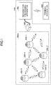
- FIG. 1 is a diagram illustrating a system configuration of an airflow measurement system according to the first embodiment.
- An airflow measurement system 100 includes a communication module group 200G, a communication terminal 300, and an information processing apparatus 400.
- the communication module group 200G includes a plurality of communication modules 200-1, 200-2, ⁇ , 200-5.
- the communication modules are referred to as communication modules 200.
- the communication module group 200G includes five communication modules 200-1, 200-2, ⁇ , 200-5 in FIG. 1 , but the number of the communication modules 200 included in the communication module group 200G is not limited to five as illustrated in FIG. 1 .
- the number of the communication modules 200 included in the communication module group 200G is not limited.
- the communication module 200 includes an airflow sensor for detecting a wind direction or a wind velocity, and a wireless communication function for transmitting data detected by the airflow sensor to the communication terminal 300. Details of the communication module 200 will be described below.
- the communication terminal 300 is an access point that relays communication between the communication module 200 and the information processing apparatus 400.
- the information processing apparatus 400 collects data from the communication module group 200G through the communication terminal 300.
- the information processing apparatus 400 analyzes the collected data and analyzes the airflow in the space where the communication module group 200G is installed.
- the information processing apparatus 400 communicates with a terminal apparatus 500 through a network or the like and outputs an analysis result to the terminal apparatus 500.
- the communication terminal 300 and the information processing apparatus 400 are provided separately, but the present invention is not limited to this configuration.
- the communication terminal 300 and the information processing apparatus 400 may be included in a single apparatus. In other words, the communication terminal 300 may be included in the information processing apparatus 400.
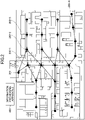
- FIG. 2 is a first diagram illustrating according to the present embodiment.
- FIG. 2 is a top view of a cleanroom 2 provided in, for example, a semiconductor integrated circuit manufacturing plant.
- a plurality of communication modules 200 are arranged in the cleanroom 2.
- the communication module 200 may be installed at any suitable location, and for example, the installation location may be decided by the administrator of the cleanroom 2.
- the communication module 200 and the communication terminal 300 of the present embodiment communicate with each other via, for example, a mesh network using Bluetooth. Accordingly, a receiving source and a transmitting destination of the information are determined for each of the communication modules 200.
- the communication module 200-1 when the communication module 200-1 receives a transmission request of the data detected by an airflow sensor 210 of the communication module 200-3 from the communication terminal 300, which is the receiving source of the information, the communication module 200-1 transmits the transmission request to the communication module 200-2, which is the transmitting destination of the information.
- the airflow sensor 210 of the communication module 200-3 receives the transmission request for the detected data from the communication module 200-1, which is the receiving source of the information, the communication module 200-2 transmits the transmission request to the communication module 200-3, which is the transmitting destination of the information.
- the communication module 200-3 returns the data detected by the airflow sensor 210 of the communication module 200-3 to the communication module 200-2 when the airflow sensor 210 receives a transmission request of the detected data from the communication module 200-1, which is the receiving source of the information.
- the communication module 200-2 returns this data to the communication module 200-1, and the communication module 200-1 returns this data to the communication terminal 300.
- such communication is repeated to collect data detected by the airflow sensor 210 in each communication module 200 included in the communication module group 200G.
- the airflow measurement system 100 may be applied to, for example, manage the airflow in a machine manufacturing factory or management of airflow in a plant growing factory.
- the communication module 200 can monitor changes in the airflow at multiple points by being installed at any location in the space. Further, in the present embodiment, since the mesh network is used, there is no need to provide multiple access points, and even in a large factory or the like in which a shield exists, airflow at multiple points can be measured with a single system. Therefore, according to the present embodiment, the airflow measurement system 100 can be easily introduced at a low cost.
- FIG. 3 is a diagram illustrating a communication module
- FIG. 4 is a diagram illustrating an airflow sensor
- FIG. 5 is a diagram illustrating a body portion.
- the communication module 200 of the present embodiment includes the airflow sensor 210 and a body portion 220.
- the airflow sensor 210 is a counter flow velocity measuring device having a flow passage forming portion 211 and a housing 212.
- the flow passage forming portion 211 and the housing 212 are fixed in the airflow sensor 210.
- the housing 212 includes an outer frame 214 which is substantially cylindrical, an annular substrate fixing portion 213 in which an opening is formed, and a bottom lid 215 which is substantially disk-shaped.
- the substrate fixing portion 213 extends inwardly from the upper end portion of the outer frame 214.
- the outer frame 214 and the substrate fixing portion 213 are integrally formed.
- a substrate fixed by the substrate fixing portion 213 is housed inside the housing 212, and a sensor element for detecting the flow direction and the flow velocity of a fluid such as air is mounted on the substrate.
- the bottom lid 215 is connected to the lower end portion of the outer frame 214.
- a plurality of through-holes are formed in the bottom lid 215 through which an external connection terminal 216 is inserted.
- the airflow sensor 210 conducts with the body portion 220 when the external connection terminal 216 is plugged into the body portion 220.
- the body portion 220 of the present embodiment includes an arithmetic processing device 221, a communication device 222, a temperature and humidity sensor 223, an atmospheric pressure sensor 224, an illuminance sensor 225, an ultraviolet (UV) sensor 226, an acceleration sensor 227, and a battery 228.
- the arithmetic processing device 221 is connected to the airflow sensor 210 by a serial bus and acquires data output from the airflow sensor 210.
- the communication device 222 communicates with a receiving source and a transmitting destination of data.
- the temperature and humidity sensor 223 detects the temperature and humidity of the space where the communication module 200 is installed.
- the temperature and humidity may be used to control the temperature and humidity of the space where communication module 200 is installed.
- the atmospheric pressure sensor 224 detects atmospheric pressure in the space where the communication module 200 is installed.
- the atmospheric pressure may be used, for example, for correcting the humidity affected by atmospheric pressure.
- the illuminance sensor 225 detects illuminance in the space where the communication module 200 is installed.
- the UV sensor 226 detects the intensity of ultraviolet rays in the space where the communication module 200 is installed.
- the acceleration sensor 227 detects acceleration of the communication module 200.
- a value detected by the acceleration sensor 227 may be used to detect that the communication module 200 has dropped from the place where the communication module 200 is installed.
- the battery 228 is a power source that supplies power to drive communication module 200.
- the body portion 220 of the present embodiment includes, the temperature and humidity sensor 223, the atmospheric pressure sensor 224, the illuminance sensor 225, the UV sensor 226, and the acceleration sensor 227, but the present invention is not limited to this configuration.
- the body portion 220 may include the arithmetic processing device 221, the communication device 222, and the battery 228, and may or may not include a sensor other than the airflow sensor 210.
- the body portion 220 according to the present embodiment may include any one or more of the temperature and humidity sensor 223, the atmospheric pressure sensor 224, the illuminance sensor 225, the UV sensor 226, and the acceleration sensor 227.
- FIG. 6 is a diagram illustrating a hardware configuration of an information processing apparatus according to the first embodiment.
- the information processing apparatus 400 is a computer including an input device 41, an output device 42, a drive device 43, an auxiliary storage device 44, a memory device 45, an arithmetic processing device 46, and an interface device 47, each of which is interconnected by a bus B.
- the input device 41 is a device for inputting various kinds of information and is implemented by, for example, a keyboard or a pointing device.
- the output device 42 is used to output various kinds of information and is implemented by, for example, a display.
- the interface device 47 includes a LAN card or the like and is used to connect to the network.
- An information processing program is at least a portion of various programs for controlling the information processing apparatus 400.
- the information processing program may be provided, for example, by a distribution of a storage medium 48 or by downloading from a network.
- the storage medium 48 on which the information processing program is recorded may use various types of storage media, for example, a storage media that optically, electrically or magnetically records information, such as a CD-ROM, a flexible disk, a magneto-optical disk, a semiconductor memory that electrically records information such as a ROM, a flash memory, and the like.
- the information processing program is installed in the auxiliary storage device 44 from the storage medium 48 via the drive device 43.
- the information processing program downloaded from the network is installed in the auxiliary storage device 44 via the interface device 47.
- the auxiliary storage device 44 implements each storage unit and the like of the information processing apparatus 400.
- the auxiliary storage device 44 stores the information processing program installed in the information processing apparatus 400 and stores various necessary files and data used by the information processing apparatus 400.
- the memory device 45 reads out the information processing program from the auxiliary storage device 44 to store at the start of the information processing apparatus 400.
- the arithmetic processing device 46 performs various processing as described below in accordance with the information processing program stored in the memory device 45.
- FIG. 7 is a diagram illustrating a function of the information processing apparatus according to the first embodiment.
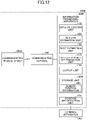
- the information processing apparatus 400 includes a data collection unit 410, an airflow estimation unit 420, a dust estimation unit 430, an affected point determination unit 440, an output unit 450, and a storage unit 460.
- the data collection unit 410, the airflow estimation unit 420, the dust estimation unit 430, the affected point determination unit 440, and the output unit 450 are functions that are implemented when the arithmetic processing device 46 of the information processing apparatus 400 reads out and executes the program stored in the memory device 45.
- the storage unit 460 is implemented by the memory device 45, the auxiliary storage device 44, or the like.
- the data collection unit 410 collects data output from each communication module 200 included in the communication module group 200G when the communication terminal 300 receives the data.
- the airflow estimation unit 420 analyzes the data collected by the data collection unit 410 and estimates the flow of air (airflow) in the space where the communication module group 200G is installed.
- the dust estimation unit 430 estimates the distribution of dust in the space according to the result of the estimation by the airflow estimation unit 420.
- the affected point determination unit 440 determines whether there is a point in the space where an airflow or dust may affect an article being managed based on the estimation result of the airflow estimation unit 420 and the dust estimation unit 430. When the corresponding point exists, the affected point determination unit 440 specifies the corresponding point and outputs information related to the corresponding point by the output unit 450.
- the output unit 450 outputs the estimation result by the airflow estimation unit 420 and the estimation result by the dust estimation unit 430.
- the output unit 450 outputs information related to the point specified by the affected point determination unit 440.
- An output destination of the output unit 450 may be, for example, a terminal apparatus 500 or a display or the like included in the information processing apparatus 400.
- Sensor position information 465 is stored in the storage unit 460.
- the sensor position information 465 is input to the information processing apparatus 400 in advance and stored in the storage unit 460.
- the sensor position information 465 is information in which identification information for identifying each communication module 200 and information indicating a position where each communication module 200 is installed are associated with each other.
- the position where the communication module 200 is installed may be three-dimensional coordinate information.
- FIG. 8 is a flowchart illustrating an operation of the information processing apparatus according to the first embodiment.
- the information processing apparatus 400 collects data from the communication module group 200G by the data collection unit 410 (step S701).
- the information processing apparatus 400 sends an instruction to the communication terminal 300 to collect data.
- the communication terminal 300 may accept the instruction and may transmit a command that instructs the communication module 200 located nearest to the communication terminal 300 to collect data.
- the data collected by the data collection unit 410 includes at least a wind direction (flow direction) and a wind velocity (flow velocity) detected by the airflow sensor 210 of each communication module 200, and identification information for specifying each communication module 200.
- the data collected by the data collection unit 410 may include data detected by each sensor of the body portion 220 of the communication module 200.
- the information processing apparatus 400 analyzes the data collected by the data collection unit 410 by the airflow estimation unit 420 referring to the sensor position information 465 and estimates the airflow in the space where the communication module group 200G is installed (step S702).
- the airflow estimation unit 420 analyzes the data collected by the data collection unit 410 and generates information for visualizing the airflow.
- the information processing apparatus 400 estimates the movement of dust in the space from the result of the estimation by the dust estimation unit 430 with the airflow estimation unit 420 (step S703).
- the dust estimation unit 430 generates information to visualize the state of dust dispersion caused by the estimated airflow.
- the information processing apparatus 400 determines whether there is a point that may affect the article being managed by the affected point determination unit 440 (step S704).
- the affected point determination unit 440 may determine a point where a certain amount or more of dust is retained as a point that may affect the article being managed.
- the article being managed may be, for example, a product manufactured in the space, or a plant cultivated in the space.
- step S704 when a corresponding point exists, the affected point determination unit 440 specifies the corresponding location (step S705) and proceeds to step S706, which will be described later.
- step S704 when the corresponding point does not exist, the information processing apparatus 400 outputs the processing result by the output unit 450 (step S706) and ends the processing.
- the output unit 450 may individually output the processing result of the data collection unit 410, the processing result of the airflow estimation unit 420, and the processing result of the dust estimation unit 430 and the affected point determination unit 440.
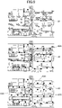
- FIG. 9 is a diagram illustrating an output example of the processing result of the first embodiment.
- a screen 81 illustrated in FIG. 9 , a screen 82 illustrated in FIG. 9 , and a screen 83 illustrated in FIG. 9 may be displayed on the terminal apparatus 500 or on the display of the information processing apparatus 400.
- the screen 81 is displayed in a state where the wind direction at each point in the space where the communication module group 200G is installed is visualized from the data collected by the data collection unit 410. Specifically, the wind direction at each point is indicated by the direction of the arrow displayed on the screen 81.
- the screen 82 is displayed in a state where the airflow estimated by the airflow estimation unit 420 is visualized. On the screen 82, a solid line 82A that indicates the airflow is displayed.
- the screen 83 is displayed in a state where the dust movement estimated by the dust estimation unit 430 and the point specified by the affected point determination unit 440 are visualized.
- the dust is displayed as a point 83B, and the point specified by the affected point determination unit 440 is surrounded by a marker 83C.
- the administrator of the space may take such measures as changing the wind direction and the wind velocity of the air conditioning in the space or frequently cleaning the point indicated by the marker 83C on the screen 83.
- a screen to be displayed may be selected from the screens 82, 83, and 84.
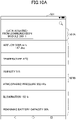
- FIG. 10A is a first diagram illustrating an example of an output of the data collected from the communication module according to the first embodiment
- FIG. 10B is a second diagram illustrating an example of an output of the data collected from the communication module according to the first embodiment.
- the screen 501 illustrated in FIG. 10A and a screen 502 illustrated in FIG. 10B are, for example, displayed on the terminal apparatus 500.
- the screen 501 is a display example of the data collected from a certain communication module 200 included in the communication module group 200G
- the screen 502 is a display example of the result of totaling the data collected from the communication module group 200G.
- the screen 501 includes a display field 501A and a display field 501B.
- the display field 501A information specifying the communication module 200 in which the data is displayed is displayed.
- the display field 501B the data acquired from the communication module 200 in display field 501A is displayed.
- the information such as "Data acquired from communication module 200-1" is displayed in the display field 501A, and data acquired from each sensor included in the communication module 200-1 among the communication modules 200 included in the communication module group 200G is displayed in the display field 501B.
- the airflow (wind velocity, wind direction), temperature, humidity, atmospheric pressure, illuminance, and the remaining battery capacity are displayed in the display field 501B.
- the screen 502 includes a display field 502A and a display field 502B.
- the display field 502A information indicating that the data is collected from the communication module group 200G is displayed.
- the display field 502B the data collected from the communication module group 200G is displayed.
- the information such as "Data collected from communication module group 200G" is displayed in the display field 502A, and a graph made from the data collected from the airflow sensor 210 of each communication module 200 included in the communication module group 200G is displayed in the display field 502B.
- the information processing apparatus 400 may display the screen 501 or the screen 502 on the terminal apparatus 500 when, for example, a display request of the data acquired from the specific communication module 200 or the data acquired from the communication module group 200G is received from the terminal apparatus 500.
- the screens illustrated in FIG. 10A and FIG. 10B are displayed on the terminal apparatus 500, but the present invention is not limited to this configuration.
- the screens illustrated in FIG. 10A and FIG. 10B may be displayed on a display or the like of the information processing apparatus 400.
- the data output by each sensor included in the communication module 200 can be collected by wireless communication from the communication module 200 set at any position. Accordingly, according to the present embodiment, the airflow can be easily measured.
- data is collected from each communication module 200 by the mesh network. That is, according to the present embodiment, even when a communication module 200 and the other communication module 200 are set in different rooms, data output from each communication module 200 can be transferred to the communication terminal 300. Therefore, according to the present embodiment, the communication module 200 can be installed in any location without being affected by the structure of the space or the like.
- a second embodiment will be described below with reference to the drawings.
- the second embodiment differs from the first embodiment in that data collected from the communication module group 200G is analyzed by the server apparatus. Therefore, in the following description of the second embodiment, the differences from the first embodiment will be described. Those having the same functional configuration as that of the first embodiment are given the same reference numerals as those used in the description of the first embodiment, and the description thereof will be omitted.
- FIG. 11 is a diagram illustrating a system configuration of an airflow measurement system according to the second embodiment.
- An airflow measurement system 100A includes a communication module group 200G, a communication terminal 300, and an information processing apparatus 400A.
- the information processing apparatus 400A is connected to a server apparatus 600 and a terminal apparatus 500 via a network.
- the information processing apparatus 400A includes a data collection unit 410 and an output unit 450.
- the information processing apparatus 400A according to the present embodiment collects data from the communication module group 200G by the data collection unit 410, and the output unit 450 outputs the collected data to the server apparatus 600.
- the output unit 450 may output collected data to the terminal apparatus 500.
- the server apparatus 600 includes a data acquisition unit 610, an airflow estimation unit 420, a dust estimation unit 430, an affected point determination unit 440, a storage unit 460, and a display control unit 620.
- the data acquisition unit 610 acquires data collected by the information processing apparatus 400A from the information processing apparatus 400A.
- the display control unit 620 displays the result of the processing by the airflow estimation unit 420, the dust estimation unit 430, and the affected point determination unit 440 on a display of the information processing apparatus 400A or the terminal apparatus 500.
- a processing load of the information processing apparatus 400A can be reduced by causing the server apparatus 600 to perform the analysis processing of the data collected from the communication module group 200G.
- a third embodiment will now be described with reference to the drawings.
- the third embodiment differs from the first embodiment in that sensor position information is generated. Therefore, in the following description of the third embodiment, the differences from the first embodiment will be described.
- Those having the same functional configuration as that of the first embodiment are given the same reference numerals as those used in the description of the first embodiment, and the description thereof will be omitted.
- FIG. 12 is a diagram illustrating a function of an information processing apparatus according to the third embodiment.
- An information processing apparatus 400B according to the present embodiment is included in an airflow measurement system 100B.
- the airflow measurement system 100B includes a communication module group 200G, a communication terminal 300, and the information processing apparatus 400B.
- the information processing apparatus 400B includes a data collection unit 410, an airflow estimation unit 420, a dust estimation unit 430, an affected point determination unit 440, an output unit 450, a storage unit 460A, and a position estimation unit 470.
- the position estimation unit 470 collects data from the communication module group 200G for a certain period of time by the data collection unit 410 and estimates the relative positional relationship of each communication module 200 based on the collected data. Then, the position estimation unit 470 generates sensor position information 465 in which the communication module 200 and the position information indicating the estimated position are associated with each other based on the estimated positional relationship, and stores the sensor position information 465 in the storage unit 460A.
- the position estimation unit 470 determines a distance between the communication modules 200 from the signal strength at the time of the communication terminal 300 receiving data from each communication module 200. Then, the position estimation unit 470 estimates the position of each communication module 200 with reference to the position where the communication terminal 300 is installed, and generates sensor position information.
- the sensor position information is generated from the signal strength when the communication terminal 300 receives the data, the sensor position information is not required to be stored in the information processing apparatus 400B in advance. That is, according to the present embodiment, when each communication module 200 is installed, the position information of the communication module 200 is not required to be input to the information processing apparatus 400, and thus the airflow measurement system 100B can be easily introduced.
- a fourth embodiment will be described below with reference to the drawings.
- the fourth embodiment differs from the first embodiment in that a communication module 200 is positioned in proximity to the particle counter. Therefore, in the following description of the fourth embodiment, the differences from the first embodiment will be described. Those having the same functional configuration as that of the first embodiment are given the same reference numerals as those used in the description of the first embodiment, and the description thereof will be omitted.
- FIG. 13 is a diagram illustrating a system configuration of an airflow measurement system according to the fourth embodiment.
- An airflow measurement system 100C according to the present embodiment includes a communication module group 200G, a particle counter 700 located in proximity to each communication module 200 included in the communication module group 200G, a communication terminal 300, and an information processing apparatus 400C.
- the particle counter 700 includes particle counters 700-1, 700-2, 700-3, 700-4, and 700-5.
- the particle counters are referred to as the particle counter 700.
- the plurality of particle counters 700 are referred to as a particle counter group 700G.
- the particle counter 700 is a measuring instrument that counts dust, dirt, foreign matter, powder, or the like, present in the air or liquid and is also referred to as a particulate matter sensor.
- the communication module 200 is located in proximity to the particle counter 700.
- the communication module 200 may be mounted on a housing or the like of the particle counter 700.
- the particle counter 700 in the present embodiment outputs the number of particles in the space. Further, the particle counter 700 of the present embodiment also communicates with the communication module 200 to inform the communication module 200 of the number of particles counted.
- the communication module 200 transmits the number of particles obtained from the particle counter 700 to the communication terminal 300 together with the data output from each sensor included in the communication module 200.
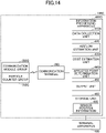
- FIG. 14 is a diagram illustrating a function of the information processing apparatus according to the fourth embodiment.
- An information processing apparatus 400C according to the present embodiment includes a data collection unit 410A, an airflow estimation unit 420, a dust estimation unit 430A, an affected point determination unit 440A, an output unit 450, and a storage unit 460.
- the communication terminal 300 receives, from the communication module group 200G, data including the number of particles output from the particle counter 700 disposed in proximity to each communication module 200.
- the data collection unit 410A collects data including the number of particles output from the particle counter 700 from the communication terminal 300.
- the dust estimation unit 430A of the present embodiment estimates the movement of dust based on the number of particles output from the particle counter 700.
- the affected point determination unit 440A determines whether there is a point where airflow or dust may affect the article according to the number of particles output from the particle counter 700.
- the affected point determination unit 440A may, for example, determine that a point where the particle counter 700 that has detected a predetermined number or more of particles is installed is a point where airflow or dust may affect the article.
- the particle counter 700 and the communication module 200 are connected, and the output of the particle counter 700 is also transferred to the communication terminal 300 via the communication module 200 thereby improving the accuracy of estimating the movement of dust.
- the airflow measurement system is configured to transfer data using a mesh network, but the present invention is not limited to this configuration.
- data output from each sensor may be transmitted from the communication module 200 to the communication terminal 300 at regular intervals.
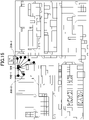
- FIG. 15 is a diagram illustrating an arrangement of the communication modules.
- each of the communication modules 200-1, 200-2, 200-3, and the like periodically transmits a signal to the communication terminal 300.
- the signal includes the data output from the sensor and the identification information of the own device.
- This configuration may be applied, for example, when the communication terminal 300 and the communication module 200 are in the same room.
- the airflow measurement system 100 is used in a cleanroom or the like provided in the semiconductor integrated circuit manufacturing plant or the like, but the airflow measurement system may be used in a room other than the cleanroom.
- the airflow measurement system 100 can be used in a negative pressure room provided in a medical institution or the like.
- the negative pressure room is a room in which the atmospheric pressure in the room is lower than that in the outside so that the air in the room does not flow out to the outside.
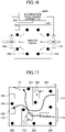
- FIG. 16 is a second diagram illustrating according to the present embodiment.
- a negative pressure room 160 illustrated in FIG. 16 is provided with an air supply fan 161 and an air exhaust fan 162, and controls the air supply fan 161 and the air exhaust fan 162 to bring the room into a negative pressure state or a positive pressure state.
- the room in the negative pressure room 160, the room is brought into a negative pressure state by controlling the air supply fan 161 and the air exhaust fan 162 such that the exhaust amount becomes larger than the supply air amount. Further, in the negative pressure room 160, the room is brought into a positive pressure state by controlling the air supply fan 161 and the air exhaust fan 162 such that the exhaust amount becomes smaller than the supply amount.
- a plurality of communication modules 200 are installed in the negative pressure room 160, and each communication module 200 detects the wind direction or wind velocity in proximity to the air supply fan 161 and the wind direction or wind velocity in proximity to the air exhaust fan 162.
- Each communication module 200 transmits the detected result to the communication terminal 300.
- the communication terminal 300 transmits the detection result collected from each communication module 200 to the information processing apparatus 400.
- the information processing apparatus 400 grasps the supply air amount and the exhaust air amount from the detection result received from the communication terminal 300.
- the information processing apparatus 400 determines that the air supply and exhaust are normal if the air supply and exhaust are carried out according to the objective amount. If either the air supply amount or the air exhaust amount is different from the objective amount, the information processing apparatus 400 determines that the negative pressure state is not maintained in the negative pressure room 160, and outputs an alert.
- the alert may be, for example, an alert notifying deterioration of the filter of the negative pressure room 160.
- the state inside the negative pressure room 160 can be monitored by using the airflow measurement system 100 of the present embodiment.
- the airflow measurement system 100 of the present embodiment can be used in an office, a store, or the like.
- an example in which the airflow measurement system 100 is used in the office will be described with reference to FIG. 17 .
- FIG. 17 is a third diagram illustrating according to the present embodiment.
- a partition, a wall, a desk, an Office Automatic (OA) device, and the like are arranged in an office 170 illustrated in FIG. 17 .
- the office 170 is provided with a door 171 and windows 172, 173, and 174, and ventilation in the office 170 is performed by opening and closing the door 171 and windows 172, 173, and 174.
- OA Office Automatic
- the wind direction or wind velocity of the air flowing into the office 170 from the windows 173 and 174 and the wind direction or wind velocity of the air flowing out of the office 170 from the door 171 and the window 172 are detected.
- the detection result is transmitted to the communication terminal 300.
- the communication terminal 300 transmits the detection result collected from each communication module 200 to the information processing apparatus 400.
- the information processing apparatus 400 determines whether the office 170 is sufficiently ventilated from the detection result received from the communication terminal 300.
- the information processing apparatus 400 may output an alert prompting the layout change in the office 170, may operate a fan 500, or the like.
- the information processing apparatus 400 may accept the setting of the airflow at the time of ventilation, and may determine that the ventilation is insufficient when the airflow does not flow in the set direction. Further, the information processing apparatus 400 may output an alert notifying the forgetting of ventilation, for example, when the airflow in the set direction is not detected for a certain period of time.
- the airflow measurement system 100 of the present embodiment may be used in a house or the like.
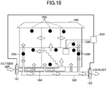
- an example in which the airflow measurement system 100 is used in a house will be described with reference to FIG. 18 .
- FIG. 18 is a fourth diagram illustrating according to the present embodiment.
- a house 180 illustrated in FIG. 18 includes a fan 181 installed outdoors to take in outside air and a fan 182 to exhaust the air inside the house 180 to the outside.
- the fan 181 installed outdoors is operated to take in the outside air indoors, and dust and pollen from the outside are removed by a filter provided inside the fan 181, and the air is drawn into the house 180 via a pipe 184 or the like.
- the air sent into the house 180 is exhausted to the outside by rotating the fan 182 via a pipe 183 or the like arranged in the house 180.
- communication modules 200 are installed in each room, and each communication module 200 detects the wind direction or the wind velocity of the installed room and transmits the detection result to the communication terminal 300.
- the communication terminal 300 transmits the detection result collected from each communication module 200 to the information processing apparatus 400.
- the information processing apparatus 400 determines that ventilation is not efficiently performed, and operates the fan 181 to draw in the outside air.
- the fan 182 is operated to exhaust the indoor air to the outside.
- the airflow measurement system 100 of the present embodiment in the house 180 or the like, it is possible to efficiently ventilate the room.
- the communication terminal 300 may be provided with the function of the information processing apparatus 400. Further, the communication terminal 300 may be, for example, a smartphone or the like.
- a user of the communication terminal 300 wears the communication module 200, so that the communication terminal 300 can estimate the degree of diffusion based on the wind direction or the wind velocity of the exhaled breath detected by the communication module 200. Therefore, the airflow measurement system 100 including the communication terminal 300 and the communication module 200 can inform the user of the communication terminal 300 of a safe distance against the spread of droplets containing viruses and the like, which can be useful for infection prevention.
Landscapes
- Engineering & Computer Science (AREA)
- Physics & Mathematics (AREA)
- General Physics & Mathematics (AREA)
- Fluid Mechanics (AREA)
- Combustion & Propulsion (AREA)
- Chemical & Material Sciences (AREA)
- Human Computer Interaction (AREA)
- Mechanical Engineering (AREA)
- General Engineering & Computer Science (AREA)
- Aviation & Aerospace Engineering (AREA)
- Arrangements For Transmission Of Measured Signals (AREA)
- Air Conditioning Control Device (AREA)
- Indicating Or Recording The Presence, Absence, Or Direction Of Movement (AREA)
Abstract
Description
- The present invention relates to an airflow measurement system and a communication module.
- Conventionally, a device for measuring the flow direction and flow velocity of a fluid, such as air, is known to be equipped with a sensor element. It is known that such a flow direction and velocity measuring device includes a housing for holding a substrate having a sensor element mounted thereon and a flow passage plate in which an outer peripheral portion is fixed to the housing by multiple support posts. Further, conventionally, the use of an airflow measuring device to measure the airflow in a data center is known.
-
- Patent Document 1:
Japanese Patent Application Laid-Open No. 2018-54528 - Patent Document 2:
Japanese Patent No. 6494811 - The above-mentioned conventional technique is complicated because it is necessary for a measurer to move the airflow measuring apparatus to an appropriate place and set the airflow measuring apparatus every time the airflow is measured.
- The technique of the present disclosure has been developed in view of the above circumstances and the purpose is to easily measure the airflow.
- The technique of the present disclosure is related to an airflow measurement system (100) including a plurality of communication modules (200) an information processing apparatus (400). The communication module includes an airflow sensor (210), and a body portion (220) including a communication unit (222) configured to acquire data output from the airflow sensor and transmit the data to outside by wireless communication. The information processing apparatus includes a data collection unit (410) configured to collect the data output from the airflow sensor of the plurality of communication modules, and an output unit (450) configured to output the collected data.
- The airflow can be easily measured.
-
-
FIG. 1 is a diagram illustrating a system configuration of an airflow measurement system according to a first embodiment; -
FIG. 2 is a first diagram illustrating a scenario in which the airflow measurement system is in use; -
FIG. 3 is a diagram illustrating a communication module; -
FIG. 4 is a diagram illustrating an airflow sensor; -
FIG. 5 is a diagram illustrating a body portion; -
FIG. 6 is a diagram illustrating a hardware configuration of an information processing apparatus according to the first embodiment; -
FIG. 7 is a diagram illustrating a function of the information processing apparatus according to the first embodiment; -
FIG. 8 is a flowchart illustrating an operation of the information processing apparatus according to the first embodiment; -
FIG. 9 is a diagram illustrating an output example of a processing result of the first embodiment; -
FIG. 10A is a first diagram illustrating an output example of data collected from the communication module according to the first embodiment; -
FIG. 10B is a second diagram illustrating an output example of data collected from the communication module according to the first embodiment; -
FIG. 11 is a diagram illustrating a system configuration of an airflow measurement system according to a second embodiment; -
FIG. 12 is a diagram illustrating a function of an information processing apparatus according to a third embodiment; -
FIG. 13 is a diagram illustrating a system configuration of an airflow measurement system according to a fourth embodiment; -
FIG. 14 is a diagram illustrating a function of the information processing apparatus according to the fourth embodiment; -
FIG. 15 is a diagram illustrating an arrangement of communication modules; -
FIG. 16 is a second diagram illustrating a scenario in which the airflow measurement system is in use; -
FIG. 17 is a third diagram illustrating a scenario in which the airflow measurement system is in use; and -
FIG. 18 is a fourth diagram illustrating a scenario in which the airflow measurement system is in use. - A first embodiment will be described with reference to the drawings.
FIG. 1 is a diagram illustrating a system configuration of an airflow measurement system according to the first embodiment. - An
airflow measurement system 100 according to the present embodiment includes acommunication module group 200G, acommunication terminal 300, and aninformation processing apparatus 400. - The
communication module group 200G includes a plurality of communication modules 200-1, 200-2, ···, 200-5. When each of the plurality of communication modules 200-1, 200-2, ···, 200-5 is not distinguished, the communication modules are referred to ascommunication modules 200. - Note that, the
communication module group 200G includes five communication modules 200-1, 200-2, ···, 200-5 inFIG. 1 , but the number of thecommunication modules 200 included in thecommunication module group 200G is not limited to five as illustrated inFIG. 1 . The number of thecommunication modules 200 included in thecommunication module group 200G is not limited. - The
communication module 200 according to the present embodiment includes an airflow sensor for detecting a wind direction or a wind velocity, and a wireless communication function for transmitting data detected by the airflow sensor to thecommunication terminal 300. Details of thecommunication module 200 will be described below. - The
communication terminal 300 is an access point that relays communication between thecommunication module 200 and theinformation processing apparatus 400. - The
information processing apparatus 400 collects data from thecommunication module group 200G through thecommunication terminal 300. Theinformation processing apparatus 400 analyzes the collected data and analyzes the airflow in the space where thecommunication module group 200G is installed. - The
information processing apparatus 400 communicates with aterminal apparatus 500 through a network or the like and outputs an analysis result to theterminal apparatus 500. - In the example of
FIG. 1 , thecommunication terminal 300 and theinformation processing apparatus 400 are provided separately, but the present invention is not limited to this configuration. Thecommunication terminal 300 and theinformation processing apparatus 400 may be included in a single apparatus. In other words, thecommunication terminal 300 may be included in theinformation processing apparatus 400. - Next, a scenario in which the
airflow measurement system 100 according to the present embodiment is in use will be described with reference toFIG. 2. FIG. 2 is a first diagram illustrating according to the present embodiment. -
FIG. 2 is a top view of a cleanroom 2 provided in, for example, a semiconductor integrated circuit manufacturing plant. In the example ofFIG. 2 , a plurality ofcommunication modules 200 are arranged in the cleanroom 2. Thecommunication module 200 may be installed at any suitable location, and for example, the installation location may be decided by the administrator of the cleanroom 2. - The
communication module 200 and thecommunication terminal 300 of the present embodiment communicate with each other via, for example, a mesh network using Bluetooth. Accordingly, a receiving source and a transmitting destination of the information are determined for each of thecommunication modules 200. - For example, when the communication module 200-1 receives a transmission request of the data detected by an
airflow sensor 210 of the communication module 200-3 from thecommunication terminal 300, which is the receiving source of the information, the communication module 200-1 transmits the transmission request to the communication module 200-2, which is the transmitting destination of the information. - When the
airflow sensor 210 of the communication module 200-3 receives the transmission request for the detected data from the communication module 200-1, which is the receiving source of the information, the communication module 200-2 transmits the transmission request to the communication module 200-3, which is the transmitting destination of the information. - The communication module 200-3 returns the data detected by the
airflow sensor 210 of the communication module 200-3 to the communication module 200-2 when theairflow sensor 210 receives a transmission request of the detected data from the communication module 200-1, which is the receiving source of the information. The communication module 200-2 returns this data to the communication module 200-1, and the communication module 200-1 returns this data to thecommunication terminal 300. - In the present embodiment, such communication is repeated to collect data detected by the
airflow sensor 210 in eachcommunication module 200 included in thecommunication module group 200G. - The
airflow measurement system 100 according to the present embodiment may be applied to, for example, manage the airflow in a machine manufacturing factory or management of airflow in a plant growing factory. - According to the present embodiment, the
communication module 200 can monitor changes in the airflow at multiple points by being installed at any location in the space. Further, in the present embodiment, since the mesh network is used, there is no need to provide multiple access points, and even in a large factory or the like in which a shield exists, airflow at multiple points can be measured with a single system. Therefore, according to the present embodiment, theairflow measurement system 100 can be easily introduced at a low cost. - Next, the
communication module 200 according to the present embodiment will be described with reference toFIG. 3 to FIG. 5 .FIG. 3 is a diagram illustrating a communication module,FIG. 4 is a diagram illustrating an airflow sensor, andFIG. 5 is a diagram illustrating a body portion. - The
communication module 200 of the present embodiment includes theairflow sensor 210 and abody portion 220. - The
airflow sensor 210 is a counter flow velocity measuring device having a flowpassage forming portion 211 and ahousing 212. The flowpassage forming portion 211 and thehousing 212 are fixed in theairflow sensor 210. - The
housing 212 includes anouter frame 214 which is substantially cylindrical, an annularsubstrate fixing portion 213 in which an opening is formed, and abottom lid 215 which is substantially disk-shaped. Thesubstrate fixing portion 213 extends inwardly from the upper end portion of theouter frame 214. For example, theouter frame 214 and thesubstrate fixing portion 213 are integrally formed. Further, a substrate fixed by thesubstrate fixing portion 213 is housed inside thehousing 212, and a sensor element for detecting the flow direction and the flow velocity of a fluid such as air is mounted on the substrate. - The
bottom lid 215 is connected to the lower end portion of theouter frame 214. A plurality of through-holes are formed in thebottom lid 215 through which anexternal connection terminal 216 is inserted. - The
airflow sensor 210 conducts with thebody portion 220 when theexternal connection terminal 216 is plugged into thebody portion 220. - The
body portion 220 of the present embodiment includes anarithmetic processing device 221, acommunication device 222, a temperature andhumidity sensor 223, anatmospheric pressure sensor 224, anilluminance sensor 225, an ultraviolet (UV)sensor 226, anacceleration sensor 227, and abattery 228. - The
arithmetic processing device 221 is connected to theairflow sensor 210 by a serial bus and acquires data output from theairflow sensor 210. Thecommunication device 222 communicates with a receiving source and a transmitting destination of data. - The temperature and
humidity sensor 223 detects the temperature and humidity of the space where thecommunication module 200 is installed. The temperature and humidity may be used to control the temperature and humidity of the space wherecommunication module 200 is installed. - The
atmospheric pressure sensor 224 detects atmospheric pressure in the space where thecommunication module 200 is installed. The atmospheric pressure may be used, for example, for correcting the humidity affected by atmospheric pressure. - The
illuminance sensor 225 detects illuminance in the space where thecommunication module 200 is installed. TheUV sensor 226 detects the intensity of ultraviolet rays in the space where thecommunication module 200 is installed. - The
acceleration sensor 227 detects acceleration of thecommunication module 200. In the present embodiment, for example, a value detected by theacceleration sensor 227 may be used to detect that thecommunication module 200 has dropped from the place where thecommunication module 200 is installed. Thebattery 228 is a power source that supplies power to drivecommunication module 200. - The
body portion 220 of the present embodiment includes, the temperature andhumidity sensor 223, theatmospheric pressure sensor 224, theilluminance sensor 225, theUV sensor 226, and theacceleration sensor 227, but the present invention is not limited to this configuration. Thebody portion 220 may include thearithmetic processing device 221, thecommunication device 222, and thebattery 228, and may or may not include a sensor other than theairflow sensor 210. Thebody portion 220 according to the present embodiment may include any one or more of the temperature andhumidity sensor 223, theatmospheric pressure sensor 224, theilluminance sensor 225, theUV sensor 226, and theacceleration sensor 227. - Next, the hardware configuration of the
information processing apparatus 400 according to the present embodiment will be described with reference toFIG. 6. FIG. 6 is a diagram illustrating a hardware configuration of an information processing apparatus according to the first embodiment. - The
information processing apparatus 400 according to the present embodiment is a computer including aninput device 41, anoutput device 42, adrive device 43, anauxiliary storage device 44, amemory device 45, anarithmetic processing device 46, and aninterface device 47, each of which is interconnected by a bus B. - The
input device 41 is a device for inputting various kinds of information and is implemented by, for example, a keyboard or a pointing device. Theoutput device 42 is used to output various kinds of information and is implemented by, for example, a display. Theinterface device 47 includes a LAN card or the like and is used to connect to the network. - An information processing program is at least a portion of various programs for controlling the
information processing apparatus 400. The information processing program may be provided, for example, by a distribution of astorage medium 48 or by downloading from a network. Thestorage medium 48 on which the information processing program is recorded may use various types of storage media, for example, a storage media that optically, electrically or magnetically records information, such as a CD-ROM, a flexible disk, a magneto-optical disk, a semiconductor memory that electrically records information such as a ROM, a flash memory, and the like. - When the
storage medium 48 in which the information processing program is recorded is set in thedrive device 43, the information processing program is installed in theauxiliary storage device 44 from thestorage medium 48 via thedrive device 43. The information processing program downloaded from the network is installed in theauxiliary storage device 44 via theinterface device 47. - The
auxiliary storage device 44 implements each storage unit and the like of theinformation processing apparatus 400. Theauxiliary storage device 44 stores the information processing program installed in theinformation processing apparatus 400 and stores various necessary files and data used by theinformation processing apparatus 400. Thememory device 45 reads out the information processing program from theauxiliary storage device 44 to store at the start of theinformation processing apparatus 400. Thearithmetic processing device 46 performs various processing as described below in accordance with the information processing program stored in thememory device 45. - Next, a function of the
information processing apparatus 400 according to the present embodiment will be described with reference toFIG. 7. FIG. 7 is a diagram illustrating a function of the information processing apparatus according to the first embodiment. - The
information processing apparatus 400 according to the present embodiment includes adata collection unit 410, anairflow estimation unit 420, adust estimation unit 430, an affectedpoint determination unit 440, anoutput unit 450, and astorage unit 460. - The
data collection unit 410, theairflow estimation unit 420, thedust estimation unit 430, the affectedpoint determination unit 440, and theoutput unit 450 according to the present embodiment are functions that are implemented when thearithmetic processing device 46 of theinformation processing apparatus 400 reads out and executes the program stored in thememory device 45. Thestorage unit 460 is implemented by thememory device 45, theauxiliary storage device 44, or the like. - The
data collection unit 410 collects data output from eachcommunication module 200 included in thecommunication module group 200G when thecommunication terminal 300 receives the data. - The
airflow estimation unit 420 analyzes the data collected by thedata collection unit 410 and estimates the flow of air (airflow) in the space where thecommunication module group 200G is installed. Thedust estimation unit 430 estimates the distribution of dust in the space according to the result of the estimation by theairflow estimation unit 420. - The affected
point determination unit 440 determines whether there is a point in the space where an airflow or dust may affect an article being managed based on the estimation result of theairflow estimation unit 420 and thedust estimation unit 430. When the corresponding point exists, the affectedpoint determination unit 440 specifies the corresponding point and outputs information related to the corresponding point by theoutput unit 450. - The
output unit 450 outputs the estimation result by theairflow estimation unit 420 and the estimation result by thedust estimation unit 430. Theoutput unit 450 outputs information related to the point specified by the affectedpoint determination unit 440. An output destination of theoutput unit 450 may be, for example, aterminal apparatus 500 or a display or the like included in theinformation processing apparatus 400. -
Sensor position information 465 is stored in thestorage unit 460. When thecommunication module group 200G is installed, thesensor position information 465 is input to theinformation processing apparatus 400 in advance and stored in thestorage unit 460. - The
sensor position information 465 is information in which identification information for identifying eachcommunication module 200 and information indicating a position where eachcommunication module 200 is installed are associated with each other. The position where thecommunication module 200 is installed may be three-dimensional coordinate information. - Next, an operation of the
information processing apparatus 400 according to the present embodiment will be described with reference toFIG. 8. FIG. 8 is a flowchart illustrating an operation of the information processing apparatus according to the first embodiment. - The
information processing apparatus 400 according to the present embodiment collects data from thecommunication module group 200G by the data collection unit 410 (step S701). - Specifically, the
information processing apparatus 400 sends an instruction to thecommunication terminal 300 to collect data. Thecommunication terminal 300 may accept the instruction and may transmit a command that instructs thecommunication module 200 located nearest to thecommunication terminal 300 to collect data. - The data collected by the
data collection unit 410 includes at least a wind direction (flow direction) and a wind velocity (flow velocity) detected by theairflow sensor 210 of eachcommunication module 200, and identification information for specifying eachcommunication module 200. The data collected by thedata collection unit 410 may include data detected by each sensor of thebody portion 220 of thecommunication module 200. - Subsequently, the
information processing apparatus 400 analyzes the data collected by thedata collection unit 410 by theairflow estimation unit 420 referring to thesensor position information 465 and estimates the airflow in the space where thecommunication module group 200G is installed (step S702). In other words, theairflow estimation unit 420 analyzes the data collected by thedata collection unit 410 and generates information for visualizing the airflow. - Subsequently, the
information processing apparatus 400 estimates the movement of dust in the space from the result of the estimation by thedust estimation unit 430 with the airflow estimation unit 420 (step S703). In other words, thedust estimation unit 430 generates information to visualize the state of dust dispersion caused by the estimated airflow. - Subsequently, the
information processing apparatus 400 determines whether there is a point that may affect the article being managed by the affected point determination unit 440 (step S704). Specifically, the affectedpoint determination unit 440 may determine a point where a certain amount or more of dust is retained as a point that may affect the article being managed. The article being managed may be, for example, a product manufactured in the space, or a plant cultivated in the space. - In step S704, when a corresponding point exists, the affected
point determination unit 440 specifies the corresponding location (step S705) and proceeds to step S706, which will be described later. - In step S704, when the corresponding point does not exist, the
information processing apparatus 400 outputs the processing result by the output unit 450 (step S706) and ends the processing. - The
output unit 450 may individually output the processing result of thedata collection unit 410, the processing result of theairflow estimation unit 420, and the processing result of thedust estimation unit 430 and the affectedpoint determination unit 440. - Next, an example of the output of the processing result of the present embodiment will be described with reference to
FIG. 9. FIG. 9 is a diagram illustrating an output example of the processing result of the first embodiment. - A
screen 81 illustrated inFIG. 9 , ascreen 82 illustrated inFIG. 9 , and ascreen 83 illustrated inFIG. 9 may be displayed on theterminal apparatus 500 or on the display of theinformation processing apparatus 400. - The
screen 81 is displayed in a state where the wind direction at each point in the space where thecommunication module group 200G is installed is visualized from the data collected by thedata collection unit 410. Specifically, the wind direction at each point is indicated by the direction of the arrow displayed on thescreen 81. - The
screen 82 is displayed in a state where the airflow estimated by theairflow estimation unit 420 is visualized. On thescreen 82, asolid line 82A that indicates the airflow is displayed. - The
screen 83 is displayed in a state where the dust movement estimated by thedust estimation unit 430 and the point specified by the affectedpoint determination unit 440 are visualized. - On the
screen 83, the dust is displayed as apoint 83B, and the point specified by the affectedpoint determination unit 440 is surrounded by amarker 83C. - In the example of
FIG. 9 , on thescreen 82, there is a point where the airflow is swirling near the center of the space, and the dust carried to this point is expected to remain. - Accordingly, the administrator of the space may take such measures as changing the wind direction and the wind velocity of the air conditioning in the space or frequently cleaning the point indicated by the
marker 83C on thescreen 83. - In the
information processing apparatus 400 according to the present embodiment, a screen to be displayed may be selected from thescreens - Next, the output of the data collected by the
data collection unit 410 will be described with reference toFIG. 10A andFIG. 10B .FIG. 10A is a first diagram illustrating an example of an output of the data collected from the communication module according to the first embodiment, andFIG. 10B is a second diagram illustrating an example of an output of the data collected from the communication module according to the first embodiment. - The
screen 501 illustrated inFIG. 10A and ascreen 502 illustrated inFIG. 10B are, for example, displayed on theterminal apparatus 500. Thescreen 501 is a display example of the data collected from acertain communication module 200 included in thecommunication module group 200G, and thescreen 502 is a display example of the result of totaling the data collected from thecommunication module group 200G. - The
screen 501 includes adisplay field 501A and adisplay field 501B. In thedisplay field 501A, information specifying thecommunication module 200 in which the data is displayed is displayed. In thedisplay field 501B, the data acquired from thecommunication module 200 indisplay field 501A is displayed. - In the example of
FIG. 10A , the information such as "Data acquired from communication module 200-1" is displayed in thedisplay field 501A, and data acquired from each sensor included in the communication module 200-1 among thecommunication modules 200 included in thecommunication module group 200G is displayed in thedisplay field 501B. - Specifically, the airflow (wind velocity, wind direction), temperature, humidity, atmospheric pressure, illuminance, and the remaining battery capacity are displayed in the
display field 501B. - The
screen 502 includes adisplay field 502A and adisplay field 502B. In thedisplay field 502A, information indicating that the data is collected from thecommunication module group 200G is displayed. In thedisplay field 502B, the data collected from thecommunication module group 200G is displayed. - In the example of
FIG. 10B , the information such as "Data collected fromcommunication module group 200G" is displayed in thedisplay field 502A, and a graph made from the data collected from theairflow sensor 210 of eachcommunication module 200 included in thecommunication module group 200G is displayed in thedisplay field 502B. - The
information processing apparatus 400 according to the present embodiment may display thescreen 501 or thescreen 502 on theterminal apparatus 500 when, for example, a display request of the data acquired from thespecific communication module 200 or the data acquired from thecommunication module group 200G is received from theterminal apparatus 500. - The screens illustrated in
FIG. 10A andFIG. 10B are displayed on theterminal apparatus 500, but the present invention is not limited to this configuration. The screens illustrated inFIG. 10A andFIG. 10B may be displayed on a display or the like of theinformation processing apparatus 400. - As described above, according to the present embodiment, the data output by each sensor included in the
communication module 200 can be collected by wireless communication from thecommunication module 200 set at any position. Accordingly, according to the present embodiment, the airflow can be easily measured. - Further, in the present embodiment, data is collected from each
communication module 200 by the mesh network. That is, according to the present embodiment, even when acommunication module 200 and theother communication module 200 are set in different rooms, data output from eachcommunication module 200 can be transferred to thecommunication terminal 300. Therefore, according to the present embodiment, thecommunication module 200 can be installed in any location without being affected by the structure of the space or the like. - A second embodiment will be described below with reference to the drawings. The second embodiment differs from the first embodiment in that data collected from the
communication module group 200G is analyzed by the server apparatus. Therefore, in the following description of the second embodiment, the differences from the first embodiment will be described. Those having the same functional configuration as that of the first embodiment are given the same reference numerals as those used in the description of the first embodiment, and the description thereof will be omitted. -
FIG. 11 is a diagram illustrating a system configuration of an airflow measurement system according to the second embodiment. - An
airflow measurement system 100A according to the present embodiment includes acommunication module group 200G, acommunication terminal 300, and aninformation processing apparatus 400A. - Further, in the
airflow measurement system 100A according to the present embodiment, theinformation processing apparatus 400A is connected to aserver apparatus 600 and aterminal apparatus 500 via a network. - The
information processing apparatus 400A according to the present embodiment includes adata collection unit 410 and anoutput unit 450. Theinformation processing apparatus 400A according to the present embodiment collects data from thecommunication module group 200G by thedata collection unit 410, and theoutput unit 450 outputs the collected data to theserver apparatus 600. Theoutput unit 450 may output collected data to theterminal apparatus 500. - The
server apparatus 600 according to the present embodiment includes adata acquisition unit 610, anairflow estimation unit 420, adust estimation unit 430, an affectedpoint determination unit 440, astorage unit 460, and adisplay control unit 620. - The
data acquisition unit 610 acquires data collected by theinformation processing apparatus 400A from theinformation processing apparatus 400A. Thedisplay control unit 620 displays the result of the processing by theairflow estimation unit 420, thedust estimation unit 430, and the affectedpoint determination unit 440 on a display of theinformation processing apparatus 400A or theterminal apparatus 500. - In the present embodiment, a processing load of the
information processing apparatus 400A can be reduced by causing theserver apparatus 600 to perform the analysis processing of the data collected from thecommunication module group 200G. - A third embodiment will now be described with reference to the drawings. The third embodiment differs from the first embodiment in that sensor position information is generated. Therefore, in the following description of the third embodiment, the differences from the first embodiment will be described. Those having the same functional configuration as that of the first embodiment are given the same reference numerals as those used in the description of the first embodiment, and the description thereof will be omitted.
-
FIG. 12 is a diagram illustrating a function of an information processing apparatus according to the third embodiment. Aninformation processing apparatus 400B according to the present embodiment is included in anairflow measurement system 100B. - The
airflow measurement system 100B includes acommunication module group 200G, acommunication terminal 300, and theinformation processing apparatus 400B. - The
information processing apparatus 400B according to the present embodiment includes adata collection unit 410, anairflow estimation unit 420, adust estimation unit 430, an affectedpoint determination unit 440, anoutput unit 450, astorage unit 460A, and aposition estimation unit 470. - The
position estimation unit 470 according to the present embodiment collects data from thecommunication module group 200G for a certain period of time by thedata collection unit 410 and estimates the relative positional relationship of eachcommunication module 200 based on the collected data. Then, theposition estimation unit 470 generatessensor position information 465 in which thecommunication module 200 and the position information indicating the estimated position are associated with each other based on the estimated positional relationship, and stores thesensor position information 465 in thestorage unit 460A. - More specifically, the
position estimation unit 470 determines a distance between thecommunication modules 200 from the signal strength at the time of thecommunication terminal 300 receiving data from eachcommunication module 200. Then, theposition estimation unit 470 estimates the position of eachcommunication module 200 with reference to the position where thecommunication terminal 300 is installed, and generates sensor position information. - In the present embodiment, since the sensor position information is generated from the signal strength when the
communication terminal 300 receives the data, the sensor position information is not required to be stored in theinformation processing apparatus 400B in advance. That is, according to the present embodiment, when eachcommunication module 200 is installed, the position information of thecommunication module 200 is not required to be input to theinformation processing apparatus 400, and thus theairflow measurement system 100B can be easily introduced. - A fourth embodiment will be described below with reference to the drawings. The fourth embodiment differs from the first embodiment in that a
communication module 200 is positioned in proximity to the particle counter. Therefore, in the following description of the fourth embodiment, the differences from the first embodiment will be described. Those having the same functional configuration as that of the first embodiment are given the same reference numerals as those used in the description of the first embodiment, and the description thereof will be omitted. -
FIG. 13 is a diagram illustrating a system configuration of an airflow measurement system according to the fourth embodiment. Anairflow measurement system 100C according to the present embodiment includes acommunication module group 200G, a particle counter 700 located in proximity to eachcommunication module 200 included in thecommunication module group 200G, acommunication terminal 300, and aninformation processing apparatus 400C. - The particle counter 700 includes particle counters 700-1, 700-2, 700-3, 700-4, and 700-5. When each of the particle counters 700-1, 700-2, 700-3, 700-4, and 700-5 is not distinguished, the particle counters are referred to as the particle counter 700. Further, the plurality of particle counters 700 are referred to as a
particle counter group 700G. - The particle counter 700 according to the present embodiment is a measuring instrument that counts dust, dirt, foreign matter, powder, or the like, present in the air or liquid and is also referred to as a particulate matter sensor.
- In the present embodiment, the
communication module 200 is located in proximity to the particle counter 700. Specifically, thecommunication module 200 may be mounted on a housing or the like of the particle counter 700. - The particle counter 700 in the present embodiment outputs the number of particles in the space. Further, the particle counter 700 of the present embodiment also communicates with the
communication module 200 to inform thecommunication module 200 of the number of particles counted. - The
communication module 200 transmits the number of particles obtained from the particle counter 700 to thecommunication terminal 300 together with the data output from each sensor included in thecommunication module 200. -
FIG. 14 is a diagram illustrating a function of the information processing apparatus according to the fourth embodiment. Aninformation processing apparatus 400C according to the present embodiment includes adata collection unit 410A, anairflow estimation unit 420, adust estimation unit 430A, an affectedpoint determination unit 440A, anoutput unit 450, and astorage unit 460. - The
communication terminal 300 according to the present embodiment receives, from thecommunication module group 200G, data including the number of particles output from the particle counter 700 disposed in proximity to eachcommunication module 200. - The
data collection unit 410A according to the present embodiment collects data including the number of particles output from the particle counter 700 from thecommunication terminal 300. - The
dust estimation unit 430A of the present embodiment estimates the movement of dust based on the number of particles output from the particle counter 700. - The affected
point determination unit 440A according to the present embodiment determines whether there is a point where airflow or dust may affect the article according to the number of particles output from the particle counter 700. - Specifically, the affected
point determination unit 440A may, for example, determine that a point where the particle counter 700 that has detected a predetermined number or more of particles is installed is a point where airflow or dust may affect the article. - In this manner, in the present embodiment, the particle counter 700 and the
communication module 200 are connected, and the output of the particle counter 700 is also transferred to thecommunication terminal 300 via thecommunication module 200 thereby improving the accuracy of estimating the movement of dust. - In each of the above-described embodiments, the airflow measurement system is configured to transfer data using a mesh network, but the present invention is not limited to this configuration.
- In the present embodiment, for example, data output from each sensor may be transmitted from the
communication module 200 to thecommunication terminal 300 at regular intervals. -
FIG. 15 is a diagram illustrating an arrangement of the communication modules. In the example ofFIG. 15 , each of the communication modules 200-1, 200-2, 200-3, and the like periodically transmits a signal to thecommunication terminal 300. The signal includes the data output from the sensor and the identification information of the own device. - This configuration may be applied, for example, when the
communication terminal 300 and thecommunication module 200 are in the same room. - In each of the above-described embodiments, the case where the
airflow measurement system 100 is used in a cleanroom or the like provided in the semiconductor integrated circuit manufacturing plant or the like has been described, but the airflow measurement system may be used in a room other than the cleanroom. - Specifically, for example, the
airflow measurement system 100 can be used in a negative pressure room provided in a medical institution or the like. Hereinafter, an example in which theairflow measurement system 100 is used in the negative pressure room will be described with reference toFIG. 16 . The negative pressure room is a room in which the atmospheric pressure in the room is lower than that in the outside so that the air in the room does not flow out to the outside. -
FIG. 16 is a second diagram illustrating according to the present embodiment. Anegative pressure room 160 illustrated inFIG. 16 is provided with anair supply fan 161 and anair exhaust fan 162, and controls theair supply fan 161 and theair exhaust fan 162 to bring the room into a negative pressure state or a positive pressure state. - Specifically, in the
negative pressure room 160, the room is brought into a negative pressure state by controlling theair supply fan 161 and theair exhaust fan 162 such that the exhaust amount becomes larger than the supply air amount. Further, in thenegative pressure room 160, the room is brought into a positive pressure state by controlling theair supply fan 161 and theair exhaust fan 162 such that the exhaust amount becomes smaller than the supply amount. - In the present embodiment, for example, a plurality of
communication modules 200 are installed in thenegative pressure room 160, and eachcommunication module 200 detects the wind direction or wind velocity in proximity to theair supply fan 161 and the wind direction or wind velocity in proximity to theair exhaust fan 162. - Each
communication module 200 transmits the detected result to thecommunication terminal 300. Thecommunication terminal 300 transmits the detection result collected from eachcommunication module 200 to theinformation processing apparatus 400. Theinformation processing apparatus 400 grasps the supply air amount and the exhaust air amount from the detection result received from thecommunication terminal 300. - Then, the
information processing apparatus 400 determines that the air supply and exhaust are normal if the air supply and exhaust are carried out according to the objective amount. If either the air supply amount or the air exhaust amount is different from the objective amount, theinformation processing apparatus 400 determines that the negative pressure state is not maintained in thenegative pressure room 160, and outputs an alert. The alert may be, for example, an alert notifying deterioration of the filter of thenegative pressure room 160. - In this way, the state inside the
negative pressure room 160 can be monitored by using theairflow measurement system 100 of the present embodiment. - Further, the
airflow measurement system 100 of the present embodiment can be used in an office, a store, or the like. Hereinafter, an example in which theairflow measurement system 100 is used in the office will be described with reference toFIG. 17 . -
FIG. 17 is a third diagram illustrating according to the present embodiment. In anoffice 170 illustrated inFIG. 17 , a partition, a wall, a desk, an Office Automatic (OA) device, and the like are arranged. Further, theoffice 170 is provided with adoor 171 andwindows office 170 is performed by opening and closing thedoor 171 andwindows - In the example of
FIG. 17 , by disposingcommunication modules 200 in various places in each area, the wind direction or wind velocity of the air flowing into theoffice 170 from thewindows office 170 from thedoor 171 and thewindow 172 are detected. The detection result is transmitted to thecommunication terminal 300. - The
communication terminal 300 transmits the detection result collected from eachcommunication module 200 to theinformation processing apparatus 400. - The
information processing apparatus 400 determines whether theoffice 170 is sufficiently ventilated from the detection result received from thecommunication terminal 300. - Then, when it is determined that the ventilation is insufficient, the
information processing apparatus 400 may output an alert prompting the layout change in theoffice 170, may operate afan 500, or the like. - Further, the
information processing apparatus 400 may accept the setting of the airflow at the time of ventilation, and may determine that the ventilation is insufficient when the airflow does not flow in the set direction. Further, theinformation processing apparatus 400 may output an alert notifying the forgetting of ventilation, for example, when the airflow in the set direction is not detected for a certain period of time. - As described above, by using the
airflow measurement system 100 of the present embodiment indoors in theoffice 170 or the like, it is possible to prevent forgetting to ventilate the room. - Further, the
airflow measurement system 100 of the present embodiment may be used in a house or the like. Hereinafter, an example in which theairflow measurement system 100 is used in a house will be described with reference toFIG. 18 . -
FIG. 18 is a fourth diagram illustrating according to the present embodiment. - A
house 180 illustrated inFIG. 18 includes afan 181 installed outdoors to take in outside air and afan 182 to exhaust the air inside thehouse 180 to the outside. - In the
house 180, thefan 181 installed outdoors is operated to take in the outside air indoors, and dust and pollen from the outside are removed by a filter provided inside thefan 181, and the air is drawn into thehouse 180 via apipe 184 or the like. - The air sent into the
house 180 is exhausted to the outside by rotating thefan 182 via apipe 183 or the like arranged in thehouse 180. - In the example of
FIG. 18 ,communication modules 200 are installed in each room, and eachcommunication module 200 detects the wind direction or the wind velocity of the installed room and transmits the detection result to thecommunication terminal 300. Thecommunication terminal 300 transmits the detection result collected from eachcommunication module 200 to theinformation processing apparatus 400. - For example, when the wind direction or the wind velocity detected in each room is below a predetermined value, the
information processing apparatus 400 determines that ventilation is not efficiently performed, and operates thefan 181 to draw in the outside air. Alternatively, thefan 182 is operated to exhaust the indoor air to the outside. - As described above, by using the
airflow measurement system 100 of the present embodiment in thehouse 180 or the like, it is possible to efficiently ventilate the room. - Further, in the present embodiment, for example, the
communication terminal 300 may be provided with the function of theinformation processing apparatus 400. Further, thecommunication terminal 300 may be, for example, a smartphone or the like. - In this case, a user of the
communication terminal 300 wears thecommunication module 200, so that thecommunication terminal 300 can estimate the degree of diffusion based on the wind direction or the wind velocity of the exhaled breath detected by thecommunication module 200. Therefore, theairflow measurement system 100 including thecommunication terminal 300 and thecommunication module 200 can inform the user of thecommunication terminal 300 of a safe distance against the spread of droplets containing viruses and the like, which can be useful for infection prevention. - The present international application is based on and claims priority to
Japanese Patent Application No. 2019-150833 filed on August 21, 2019 -
- 100, 100A, 100B, 100C
- airflow measurement system
- 200
- communication module
- 210
- airflow sensor
- 220
- body portion
- 300
- communication terminal
- 400, 400A, 400B, 400C
- information processing apparatus
- 410, 410A
- data collection unit
- 420
- airflow estimation unit
- 430, 430A
- dust estimation unit
- 440, 440A
- affected point determination unit
- 450
- output unit
- 460
- storage unit
- 465
- sensor position information
- 470
- position estimation unit
- 500
- terminal apparatus
- 600
- server apparatus
Claims (10)
- An airflow measurement system comprising:a plurality of communication modules; andan information processing apparatus,wherein the communication module includes an airflow sensor, and a body portion including a communication unit configured to acquire data output from the airflow sensor and transmit the data to outside by wireless communication, and,wherein the information processing apparatus includes a data collection unit configured to collect the data output from the airflow sensor of the plurality of communication modules, and an output unit configured to output the collected data.
- The airflow measurement system according to claim 1, wherein the information processing apparatus further includes an airflow estimation unit configured to estimate a state of an airflow in a space where the plurality of communication modules are disposed, the airflow being estimated based on the collected data.
- The airflow measurement system according to claim 2, wherein the information processing apparatus further includes a dust estimation unit configured to estimate movement of dust in the space where the plurality of communication modules are disposed based on the collected data.
- The airflow measurement system according to claim 3, wherein the communication module is disposed in proximity to a particulate matter sensor, acquires a measurement result measured by the particulate matter sensor, and transmits the measurement result, to the information processing apparatus, together with the data output from the airflow sensor.
- The airflow measurement system according to claim 4, wherein the output unit displays an estimation result by the airflow estimation unit and an estimation result by the dust estimation unit on a display device.
- The airflow measurement system according to claim 5, wherein the plurality of communication modules and the information processing apparatus communicate with each other via a communication terminal.
- The airflow measurement system according to claim 6, the plurality of communication modules and the communication terminal communicate with each other using a mesh network.
- A communication module comprising:an airflow sensor; anda body portion including a communication unit configured to acquire data output from the airflow sensor and transmit the data to outside by wireless communication.
- The communication module according to claim 8, wherein the body portion includes at least one of a temperature sensor, a humidity sensor, an acceleration sensor, an illuminance sensor, and an ultraviolet sensor.
- The communication module according to claim 8, wherein the airflow sensor detects a flow direction or a flow velocity of air in a space where the communication module is installed.
Applications Claiming Priority (2)
| Application Number | Priority Date | Filing Date | Title |
|---|---|---|---|
| JP2019150833 | 2019-08-21 | ||
| PCT/JP2020/028010 WO2021033475A1 (en) | 2019-08-21 | 2020-07-20 | Airflow measurement system and communication module |
Publications (2)
| Publication Number | Publication Date |
|---|---|
| EP4001926A1 true EP4001926A1 (en) | 2022-05-25 |
| EP4001926A4 EP4001926A4 (en) | 2022-09-07 |
Family
ID=74660853
Family Applications (1)
| Application Number | Title | Priority Date | Filing Date |
|---|---|---|---|
| EP20854984.0A Withdrawn EP4001926A4 (en) | 2019-08-21 | 2020-07-20 | AIR FLOW MEASUREMENT SYSTEM AND COMMUNICATION MODULE |
Country Status (5)
| Country | Link |
|---|---|
| US (1) | US12135229B2 (en) |
| EP (1) | EP4001926A4 (en) |
| JP (1) | JP7415116B2 (en) |
| CN (1) | CN114342426A (en) |
| WO (1) | WO2021033475A1 (en) |
Cited By (1)
| Publication number | Priority date | Publication date | Assignee | Title |
|---|---|---|---|---|
| US20210364545A1 (en) * | 2020-05-20 | 2021-11-25 | Viu Insight Inc. | Air measuring device and methods of use |
Family Cites Families (22)
| Publication number | Priority date | Publication date | Assignee | Title |
|---|---|---|---|---|
| JP2001264180A (en) * | 2000-03-14 | 2001-09-26 | Yazaki Corp | Environment measuring device and method |
| JP2005003313A (en) | 2003-06-13 | 2005-01-06 | Daikin Ind Ltd | Air conditioning diagnostic system |
| JP5381277B2 (en) | 2009-04-23 | 2014-01-08 | オムロン株式会社 | Blower control pattern creation device |
| JP5674193B2 (en) * | 2010-09-15 | 2015-02-25 | 大成建設株式会社 | Air conditioning environment monitoring system |
| US9195243B2 (en) * | 2011-05-24 | 2015-11-24 | Aten International Co., Ltd. | System and method of safe and effective energy usage and conservation for data centers with rack power distribution units |
| JP5666393B2 (en) * | 2011-06-28 | 2015-02-12 | セイコーインスツル株式会社 | Sensor network system |
| EP2895798B1 (en) | 2012-08-03 | 2019-12-04 | Synapsense Corporation | Apparatus and method for controlling computer room air conditioning units (cracs) in data centers |
| JP5949298B2 (en) * | 2012-08-07 | 2016-07-06 | 富士通株式会社 | Communication method and information processing apparatus |
| DK178244B1 (en) * | 2013-06-21 | 2015-09-28 | Agena As | A system or a method for measuring flow in a flow duct |
| JP6354538B2 (en) * | 2014-11-21 | 2018-07-11 | 株式会社デンソー | Communication system, flow rate measuring device and control device |
| JP2017004279A (en) * | 2015-06-11 | 2017-01-05 | 横河電機株式会社 | Information collection system, information collection terminal device, information collection server device, and information collection method |
| US20170188486A1 (en) * | 2015-12-29 | 2017-06-29 | Schneider Electric It Corporation | Rack airflow monitoring system and method |
| JP6856865B2 (en) | 2016-09-30 | 2021-04-14 | ミツミ電機株式会社 | Flow direction flow velocity measuring device |
| CN108803502B (en) * | 2017-04-27 | 2022-07-26 | 横河电机株式会社 | Data collection device and system, data server, data collection method, and computer-readable non-volatile recording medium |
| US11385096B2 (en) * | 2017-05-15 | 2022-07-12 | Sensidyne, L.P. | Airflow calibrator |
| ES3061858T3 (en) * | 2017-06-29 | 2026-04-07 | American Air Filter Company Inc | Sensor array environment for an air handling unit |
| FI128408B (en) * | 2017-07-07 | 2020-04-30 | Flaekt Woods Ab | Equipment and method for measuring an airflow |
| EP3645948A4 (en) * | 2017-07-14 | 2020-07-15 | Ebtron, Inc. | AIRFLOW SENSORS, SYSTEMS AND METHODS |
| US20190128550A1 (en) | 2017-11-02 | 2019-05-02 | Campos Engineering, Inc. | Intelligent wireless test and balance system |
| JP6494811B1 (en) | 2018-01-12 | 2019-04-03 | 三菱電機ビルテクノサービス株式会社 | Thermal airflow measuring device, thermal airflow measuring system, and thermal airflow image generating method |
| JP6979901B2 (en) | 2018-02-28 | 2021-12-15 | ダイハツ工業株式会社 | Resistance welding method |
| US20200290410A1 (en) * | 2019-03-11 | 2020-09-17 | Huf Baolong Electronics Bretten Gmbh | System and method for assigning a protocol to a sensor |
-
2020
- 2020-07-20 CN CN202080059043.0A patent/CN114342426A/en active Pending
- 2020-07-20 EP EP20854984.0A patent/EP4001926A4/en not_active Withdrawn
- 2020-07-20 US US17/635,456 patent/US12135229B2/en active Active
- 2020-07-20 JP JP2021540675A patent/JP7415116B2/en active Active
- 2020-07-20 WO PCT/JP2020/028010 patent/WO2021033475A1/en not_active Ceased
Cited By (2)
| Publication number | Priority date | Publication date | Assignee | Title |
|---|---|---|---|---|
| US20210364545A1 (en) * | 2020-05-20 | 2021-11-25 | Viu Insight Inc. | Air measuring device and methods of use |
| US12019093B2 (en) * | 2020-05-20 | 2024-06-25 | Viu Insight Inc. | Air measuring device and methods of use |
Also Published As
| Publication number | Publication date |
|---|---|
| US12135229B2 (en) | 2024-11-05 |
| EP4001926A4 (en) | 2022-09-07 |
| JP7415116B2 (en) | 2024-01-17 |
| US20220291030A1 (en) | 2022-09-15 |
| WO2021033475A1 (en) | 2021-02-25 |
| JPWO2021033475A1 (en) | 2021-02-25 |
| CN114342426A (en) | 2022-04-12 |
Similar Documents
| Publication | Publication Date | Title |
|---|---|---|
| US11841313B2 (en) | Power management for optical particle counters | |
| TWI827547B (en) | Powered air-handling system, method of monitoring an air filter including air filter media installed in a powered air-handling system, and related machine readable storage device | |
| TWI749044B (en) | Air filter condition sensing | |
| US20080281528A1 (en) | System and Method for Environmental Sampling and Diagnostic Evaluation | |
| ES3061858T3 (en) | Sensor array environment for an air handling unit | |
| US9729945B2 (en) | Environmental monitor device with database | |
| US12157080B2 (en) | Air filter apparatus, system and method | |
| EP2188617B1 (en) | Particle counting system having an environmental sensor and method of operating the same | |
| US20140053586A1 (en) | System and apparatus for using a wireless smart device to perform field calculations | |
| US12436084B2 (en) | Modular optical particle counter sensor and apparatus | |
| US20070256643A1 (en) | Remote animal cage environmental monitoring and control system | |
| US20160061477A1 (en) | Environmental Sensing System | |
| US20160061794A1 (en) | Environmental Sensor Device with Thresholding | |
| US20160066067A1 (en) | Patient Satisfaction Sensor Device | |
| US20160063841A1 (en) | Environmental Monitor Device | |
| US20160061476A1 (en) | Environmental Sensor Device | |
| US20160063833A1 (en) | Environmental Sensor Device with Alarms | |
| US12135229B2 (en) | Airflow measurement system including a communication module group | |
| US20120229277A1 (en) | Monitoring and alert system for ventilated rack systems | |
| EP3745038A1 (en) | Device, system and method for monitoring air quality in a closed environment | |
| US10094755B1 (en) | Environmental sensor and method of operating the same | |
| US11585799B2 (en) | System for monitoring the probability of viral disease transmission | |
| WO2020044754A1 (en) | Monitoring device and monitoring system | |
| KR20240102048A (en) | Ai indoor air quality monitoring system and method based on complex total airborne bacteria analysis device | |
| CN210486945U (en) | Gas detection device |
Legal Events
| Date | Code | Title | Description |
|---|---|---|---|
| STAA | Information on the status of an ep patent application or granted ep patent |
Free format text: STATUS: THE INTERNATIONAL PUBLICATION HAS BEEN MADE |
|
| PUAI | Public reference made under article 153(3) epc to a published international application that has entered the european phase |
Free format text: ORIGINAL CODE: 0009012 |
|
| STAA | Information on the status of an ep patent application or granted ep patent |
Free format text: STATUS: REQUEST FOR EXAMINATION WAS MADE |
|
| 17P | Request for examination filed |
Effective date: 20220217 |
|
| AK | Designated contracting states |
Kind code of ref document: A1 Designated state(s): AL AT BE BG CH CY CZ DE DK EE ES FI FR GB GR HR HU IE IS IT LI LT LU LV MC MK MT NL NO PL PT RO RS SE SI SK SM TR |
|
| A4 | Supplementary search report drawn up and despatched |
Effective date: 20220808 |
|
| RIC1 | Information provided on ipc code assigned before grant |
Ipc: F24F 11/00 20180101ALI20220802BHEP Ipc: G01P 5/00 20060101ALI20220802BHEP Ipc: G01P 13/00 20060101AFI20220802BHEP |
|
| DAV | Request for validation of the european patent (deleted) | ||
| DAX | Request for extension of the european patent (deleted) | ||
| STAA | Information on the status of an ep patent application or granted ep patent |
Free format text: STATUS: EXAMINATION IS IN PROGRESS |
|
| 17Q | First examination report despatched |
Effective date: 20240215 |
|
| STAA | Information on the status of an ep patent application or granted ep patent |
Free format text: STATUS: THE APPLICATION IS DEEMED TO BE WITHDRAWN |
|
| 18D | Application deemed to be withdrawn |
Effective date: 20251001 |