EP4001871B1 - Vorrichtung und verfahren zur schätzung der körpertemperatur sowie eine gesundheitspflegevorrichtung - Google Patents
Vorrichtung und verfahren zur schätzung der körpertemperatur sowie eine gesundheitspflegevorrichtung Download PDFInfo
- Publication number
- EP4001871B1 EP4001871B1 EP21190304.2A EP21190304A EP4001871B1 EP 4001871 B1 EP4001871 B1 EP 4001871B1 EP 21190304 A EP21190304 A EP 21190304A EP 4001871 B1 EP4001871 B1 EP 4001871B1
- Authority
- EP
- European Patent Office
- Prior art keywords
- temperature
- spectrum
- light
- body temperature
- estimating
- Prior art date
- Legal status (The legal status is an assumption and is not a legal conclusion. Google has not performed a legal analysis and makes no representation as to the accuracy of the status listed.)
- Active
Links
Images





Classifications
-
- G—PHYSICS
- G01—MEASURING; TESTING
- G01K—MEASURING TEMPERATURE; MEASURING QUANTITY OF HEAT; THERMALLY-SENSITIVE ELEMENTS NOT OTHERWISE PROVIDED FOR
- G01K11/00—Measuring temperature based upon physical or chemical changes not covered by groups G01K3/00, G01K5/00, G01K7/00 or G01K9/00
- G01K11/006—Measuring temperature based upon physical or chemical changes not covered by groups G01K3/00, G01K5/00, G01K7/00 or G01K9/00 using measurement of the effect of a material on microwaves or longer electromagnetic waves, e.g. measuring temperature via microwaves emitted by the object
-
- A—HUMAN NECESSITIES
- A61—MEDICAL OR VETERINARY SCIENCE; HYGIENE
- A61B—DIAGNOSIS; SURGERY; IDENTIFICATION
- A61B5/00—Measuring for diagnostic purposes; Identification of persons
- A61B5/01—Measuring temperature of body parts ; Diagnostic temperature sensing, e.g. for malignant or inflamed tissue
-
- G—PHYSICS
- G01—MEASURING; TESTING
- G01K—MEASURING TEMPERATURE; MEASURING QUANTITY OF HEAT; THERMALLY-SENSITIVE ELEMENTS NOT OTHERWISE PROVIDED FOR
- G01K13/00—Thermometers specially adapted for specific purposes
- G01K13/20—Clinical contact thermometers for use with humans or animals
-
- A—HUMAN NECESSITIES
- A61—MEDICAL OR VETERINARY SCIENCE; HYGIENE
- A61B—DIAGNOSIS; SURGERY; IDENTIFICATION
- A61B5/00—Measuring for diagnostic purposes; Identification of persons
- A61B5/0059—Measuring for diagnostic purposes; Identification of persons using light, e.g. diagnosis by transillumination, diascopy, fluorescence
- A61B5/0075—Measuring for diagnostic purposes; Identification of persons using light, e.g. diagnosis by transillumination, diascopy, fluorescence by spectroscopy, i.e. measuring spectra, e.g. Raman spectroscopy, infrared absorption spectroscopy
-
- A—HUMAN NECESSITIES
- A61—MEDICAL OR VETERINARY SCIENCE; HYGIENE
- A61B—DIAGNOSIS; SURGERY; IDENTIFICATION
- A61B5/00—Measuring for diagnostic purposes; Identification of persons
- A61B5/05—Detecting, measuring or recording for diagnosis by means of electric currents or magnetic fields; Measuring using microwaves or radio waves
- A61B5/053—Measuring electrical impedance or conductance of a portion of the body
- A61B5/0537—Measuring body composition by impedance, e.g. tissue hydration or fat content
-
- A—HUMAN NECESSITIES
- A61—MEDICAL OR VETERINARY SCIENCE; HYGIENE
- A61B—DIAGNOSIS; SURGERY; IDENTIFICATION
- A61B5/00—Measuring for diagnostic purposes; Identification of persons
- A61B5/145—Measuring characteristics of blood in vivo, e.g. gas concentration or pH-value ; Measuring characteristics of body fluids or tissues, e.g. interstitial fluid or cerebral tissue
- A61B5/14532—Measuring characteristics of blood in vivo, e.g. gas concentration or pH-value ; Measuring characteristics of body fluids or tissues, e.g. interstitial fluid or cerebral tissue for measuring glucose, e.g. by tissue impedance measurement
-
- A—HUMAN NECESSITIES
- A61—MEDICAL OR VETERINARY SCIENCE; HYGIENE
- A61B—DIAGNOSIS; SURGERY; IDENTIFICATION
- A61B5/00—Measuring for diagnostic purposes; Identification of persons
- A61B5/16—Devices for psychotechnics; Testing reaction times ; Devices for evaluating the psychological state
- A61B5/165—Evaluating the state of mind, e.g. depression, anxiety
-
- A—HUMAN NECESSITIES
- A61—MEDICAL OR VETERINARY SCIENCE; HYGIENE
- A61B—DIAGNOSIS; SURGERY; IDENTIFICATION
- A61B5/00—Measuring for diagnostic purposes; Identification of persons
- A61B5/68—Arrangements of detecting, measuring or recording means, e.g. sensors, in relation to patient
- A61B5/6801—Arrangements of detecting, measuring or recording means, e.g. sensors, in relation to patient specially adapted to be attached to or worn on the body surface
- A61B5/6802—Sensor mounted on worn items
-
- A—HUMAN NECESSITIES
- A61—MEDICAL OR VETERINARY SCIENCE; HYGIENE
- A61B—DIAGNOSIS; SURGERY; IDENTIFICATION
- A61B5/00—Measuring for diagnostic purposes; Identification of persons
- A61B5/68—Arrangements of detecting, measuring or recording means, e.g. sensors, in relation to patient
- A61B5/6801—Arrangements of detecting, measuring or recording means, e.g. sensors, in relation to patient specially adapted to be attached to or worn on the body surface
- A61B5/6802—Sensor mounted on worn items
- A61B5/6803—Head-worn items, e.g. helmets, masks, headphones or goggles
-
- A—HUMAN NECESSITIES
- A61—MEDICAL OR VETERINARY SCIENCE; HYGIENE
- A61B—DIAGNOSIS; SURGERY; IDENTIFICATION
- A61B5/00—Measuring for diagnostic purposes; Identification of persons
- A61B5/68—Arrangements of detecting, measuring or recording means, e.g. sensors, in relation to patient
- A61B5/6801—Arrangements of detecting, measuring or recording means, e.g. sensors, in relation to patient specially adapted to be attached to or worn on the body surface
- A61B5/6802—Sensor mounted on worn items
- A61B5/681—Wristwatch-type devices
-
- A—HUMAN NECESSITIES
- A61—MEDICAL OR VETERINARY SCIENCE; HYGIENE
- A61B—DIAGNOSIS; SURGERY; IDENTIFICATION
- A61B5/00—Measuring for diagnostic purposes; Identification of persons
- A61B5/68—Arrangements of detecting, measuring or recording means, e.g. sensors, in relation to patient
- A61B5/6801—Arrangements of detecting, measuring or recording means, e.g. sensors, in relation to patient specially adapted to be attached to or worn on the body surface
- A61B5/683—Means for maintaining contact with the body
- A61B5/6832—Means for maintaining contact with the body using adhesives
- A61B5/6833—Adhesive patches
-
- A—HUMAN NECESSITIES
- A61—MEDICAL OR VETERINARY SCIENCE; HYGIENE
- A61B—DIAGNOSIS; SURGERY; IDENTIFICATION
- A61B5/00—Measuring for diagnostic purposes; Identification of persons
- A61B5/68—Arrangements of detecting, measuring or recording means, e.g. sensors, in relation to patient
- A61B5/6887—Arrangements of detecting, measuring or recording means, e.g. sensors, in relation to patient mounted on external non-worn devices, e.g. non-medical devices
- A61B5/6898—Portable consumer electronic devices, e.g. music players, telephones, tablet computers
-
- A—HUMAN NECESSITIES
- A61—MEDICAL OR VETERINARY SCIENCE; HYGIENE
- A61B—DIAGNOSIS; SURGERY; IDENTIFICATION
- A61B5/00—Measuring for diagnostic purposes; Identification of persons
- A61B5/72—Signal processing specially adapted for physiological signals or for diagnostic purposes
- A61B5/7271—Specific aspects of physiological measurement analysis
- A61B5/7275—Determining trends in physiological measurement data; Predicting development of a medical condition based on physiological measurements, e.g. determining a risk factor
-
- G—PHYSICS
- G01—MEASURING; TESTING
- G01K—MEASURING TEMPERATURE; MEASURING QUANTITY OF HEAT; THERMALLY-SENSITIVE ELEMENTS NOT OTHERWISE PROVIDED FOR
- G01K11/00—Measuring temperature based upon physical or chemical changes not covered by groups G01K3/00, G01K5/00, G01K7/00 or G01K9/00
- G01K11/12—Measuring temperature based upon physical or chemical changes not covered by groups G01K3/00, G01K5/00, G01K7/00 or G01K9/00 using changes in colour, translucency or reflectance
-
- G—PHYSICS
- G01—MEASURING; TESTING
- G01K—MEASURING TEMPERATURE; MEASURING QUANTITY OF HEAT; THERMALLY-SENSITIVE ELEMENTS NOT OTHERWISE PROVIDED FOR
- G01K7/00—Measuring temperature based on the use of electric or magnetic elements directly sensitive to heat ; Power supply therefor, e.g. using thermoelectric elements
- G01K7/42—Circuits effecting compensation of thermal inertia; Circuits for predicting the stationary value of a temperature
-
- G—PHYSICS
- G01—MEASURING; TESTING
- G01K—MEASURING TEMPERATURE; MEASURING QUANTITY OF HEAT; THERMALLY-SENSITIVE ELEMENTS NOT OTHERWISE PROVIDED FOR
- G01K7/00—Measuring temperature based on the use of electric or magnetic elements directly sensitive to heat ; Power supply therefor, e.g. using thermoelectric elements
- G01K7/42—Circuits effecting compensation of thermal inertia; Circuits for predicting the stationary value of a temperature
- G01K7/427—Temperature calculation based on spatial modeling, e.g. spatial inter- or extrapolation
-
- A—HUMAN NECESSITIES
- A61—MEDICAL OR VETERINARY SCIENCE; HYGIENE
- A61B—DIAGNOSIS; SURGERY; IDENTIFICATION
- A61B2560/00—Constructional details of operational features of apparatus; Accessories for medical measuring apparatus
- A61B2560/02—Operational features
- A61B2560/0242—Operational features adapted to measure environmental factors, e.g. temperature, pollution
- A61B2560/0247—Operational features adapted to measure environmental factors, e.g. temperature, pollution for compensation or correction of the measured physiological value
-
- A—HUMAN NECESSITIES
- A61—MEDICAL OR VETERINARY SCIENCE; HYGIENE
- A61B—DIAGNOSIS; SURGERY; IDENTIFICATION
- A61B2562/00—Details of sensors; Constructional details of sensor housings or probes; Accessories for sensors
- A61B2562/02—Details of sensors specially adapted for in-vivo measurements
- A61B2562/0271—Thermal or temperature sensors
-
- A—HUMAN NECESSITIES
- A61—MEDICAL OR VETERINARY SCIENCE; HYGIENE
- A61B—DIAGNOSIS; SURGERY; IDENTIFICATION
- A61B5/00—Measuring for diagnostic purposes; Identification of persons
- A61B5/02—Detecting, measuring or recording for evaluating the cardiovascular system, e.g. pulse, heart rate, blood pressure or blood flow
- A61B5/021—Measuring pressure in heart or blood vessels
-
- A—HUMAN NECESSITIES
- A61—MEDICAL OR VETERINARY SCIENCE; HYGIENE
- A61B—DIAGNOSIS; SURGERY; IDENTIFICATION
- A61B5/00—Measuring for diagnostic purposes; Identification of persons
- A61B5/145—Measuring characteristics of blood in vivo, e.g. gas concentration or pH-value ; Measuring characteristics of body fluids or tissues, e.g. interstitial fluid or cerebral tissue
- A61B5/14546—Measuring characteristics of blood in vivo, e.g. gas concentration or pH-value ; Measuring characteristics of body fluids or tissues, e.g. interstitial fluid or cerebral tissue for measuring analytes not otherwise provided for, e.g. ions, cytochromes
-
- A—HUMAN NECESSITIES
- A61—MEDICAL OR VETERINARY SCIENCE; HYGIENE
- A61B—DIAGNOSIS; SURGERY; IDENTIFICATION
- A61B5/00—Measuring for diagnostic purposes; Identification of persons
- A61B5/44—Detecting, measuring or recording for evaluating the integumentary system, e.g. skin, hair or nails
- A61B5/441—Skin evaluation, e.g. for skin disorder diagnosis
- A61B5/442—Evaluating skin mechanical properties, e.g. elasticity, hardness, texture, wrinkle assessment
-
- A—HUMAN NECESSITIES
- A61—MEDICAL OR VETERINARY SCIENCE; HYGIENE
- A61B—DIAGNOSIS; SURGERY; IDENTIFICATION
- A61B5/00—Measuring for diagnostic purposes; Identification of persons
- A61B5/48—Other medical applications
- A61B5/4869—Determining body composition
- A61B5/4872—Body fat
-
- A—HUMAN NECESSITIES
- A61—MEDICAL OR VETERINARY SCIENCE; HYGIENE
- A61B—DIAGNOSIS; SURGERY; IDENTIFICATION
- A61B5/00—Measuring for diagnostic purposes; Identification of persons
- A61B5/48—Other medical applications
- A61B5/4869—Determining body composition
- A61B5/4875—Hydration status, fluid retention of the body
-
- A—HUMAN NECESSITIES
- A61—MEDICAL OR VETERINARY SCIENCE; HYGIENE
- A61B—DIAGNOSIS; SURGERY; IDENTIFICATION
- A61B5/00—Measuring for diagnostic purposes; Identification of persons
- A61B5/72—Signal processing specially adapted for physiological signals or for diagnostic purposes
- A61B5/7235—Details of waveform analysis
- A61B5/7264—Classification of physiological signals or data, e.g. using neural networks, statistical classifiers, expert systems or fuzzy systems
Definitions
- Apparatuses and methods consistent with example embodiments relate to estimating body temperature by using an optical sensor.
- body temperature is one of the four main vital signs and has very important clinical significance.
- a body temperature sensor may be used in various applications, such as checking infections in patients, thermal side effects of medications, or time of ovulation in women, and the like.
- the skin temperature and deep body temperature may vary depending on external temperature, such that it is difficult to measure the deep body temperature by using a portable device such as a wearable device.
- a general body temperature sensor may be classified into a contact type sensor and a non-contact type sensor. Examples of the contact type sensor may include a sensor for detecting a change in electrical resistance, such as a Resistance Temperature Detector (RTD), a thermistor, etc., a thermocouple for detecting electromotive force, and the like.
- RTD Resistance Temperature Detector
- non-contact type sensor may include a thermopile, a micro-bolometer, and the like, which measure body temperature by detecting infrared rays radiating from a body surface.
- thermopile a thermopile
- micro-bolometer a micro-bolometer
- a general body temperature measuring technology is affected significantly by a change in environment factors affecting heat transfer, such as a change in external ambient temperature, humidity, air flow, and the like.
- US 2018/188117 A1 discloses to a clinical thermometer for non-invasive measurement of subcutaneous temperature of tissue of a human or animal subject.
- Probe light is collected from a collection region spatially offset from an entry region on a visible surface of the subject, following scattering within the tissue, and a temperature of the tissue is determined from Raman spectral features in the collected light.
- US 2017/319066 A1 discloses a temperature measurement device, comprising a spectral measurement system, configured to determine the absorbance of tissue at a plurality of frequencies, and an analysis system, configured to determine the temperature of the tissue from the determined absorbance, wherein water has a temperature dependent absorption at one of the plurality of frequencies that is different than that at another of the plurality of frequencies.
- an apparatus for estimating body temperature including: a sensor configured to obtain spectra through a plurality of light paths of an object; and a processor configured to obtain a temperature slope between temperatures corresponding to the plurality of light paths based on the spectra of the plurality of light paths and a reference spectrum measured at a reference temperature, and estimate the body temperature of the object based on the temperature slope, wherein the temperature slope is a change of mean temperatures between the respective paths.
- the reference spectrum may be measured by using a light in a water absorption wavelength range.
- the sensor may include: a light source configured to emit light onto the object; and a detector configured to detect the light scattered or reflected from the object after the light is emitted by the light source.
- At least one of the plurality of light paths may penetrate into a depth of dermis or another depth deeper than the depth of dermis.
- the processor may be further configured to normalize the spectra of the plurality of light paths, respectively, based on the reference spectrum, and obtain the temperature slope based on the normalized spectra of the plurality of light paths.
- the processor may be further configured to estimate a mean temperature of each of the respective plurality of light paths based on a difference between the reference spectrum and the respective spectra of the plurality of light paths, and obtain the temperature slope based on each of the estimated mean temperatures.
- the processor may be further configured to estimate the body temperature of the object based on the reference temperature and the temperature slope by using a body temperature estimation equation.
- the processor may be further configured to: estimate a mean temperature of a reference path selected from the plurality of light paths; and estimate the body temperature of the object based on the temperature slope and the mean temperature of the reference path by using the body temperature estimation equation.
- the processor may be further configured to determine a shortest light path among the plurality of light paths as the reference path.
- the apparatus may further include an output interface configured to output the estimated body temperature of the object.
- a healthcare device including: a main body including the apparatus for estimating the body temperature; a display mounted on the main body, wherein the processor may be further configured to perform at least one of a first mode of estimating the body temperature of the object, a second mode of estimating bio-information based on the obtained spectra, and a third mode of estimating the body temperature and the bio-information, and control the display to display a result of performing at least one of the first mode, the second mode, and the third mode.
- an apparatus for estimating body temperature including: a spectrometer configured to obtain a spectrum through a light path passing through a tissue underneath a surface of an object; a temperature sensor configured to measure a surface temperature from the surface of the object; and a processor configured to obtain a temperature slope between a temperature corresponding to the obtained spectrum and the surface temperature, based on the obtained spectrum and a reference spectrum corresponding to the surface temperature, and estimate the body temperature of the object based on the temperature slope.
- the processor may be further configured to normalize the spectrum obtained through the light path based on a reference spectrum corresponding to the surface temperature, and obtain the temperature slope based on the normalized spectrum.
- the processor may be further configured to estimate a mean temperature of the light path based on a difference between the reference spectrum and the normalized spectrum, and obtain the temperature slope based on the surface temperature and the mean temperature.
- the processor may be further configured to estimate the body temperature of the object based on the surface temperature and the temperature slope by using a body temperature estimation equation.
- a method of estimating body temperature including: obtaining spectra through a plurality of light paths of an object; obtaining a temperature slope between temperatures corresponding to the plurality of light paths based on the spectra of the plurality of light paths and a reference spectrum measured at a reference temperature; and estimating the body temperature of the object based on the temperature slope, wherein the temperature slope is a change of mean temperatures between the respective paths.
- the obtaining the temperature slope may include normalizing the spectra of the plurality of light paths, respectively, based on the reference spectrum, and obtaining the temperature slope based on the normalized spectra of the plurality of light paths.
- the obtaining the temperature slope may include estimating a mean temperature of the plurality of light paths based on a difference between the reference spectrum and the normalized spectra of the plurality of light paths, and obtaining the temperature slope based on the estimated mean temperature.
- the estimating the body temperature may include estimating the body temperature of the object based on the reference temperature and the temperature slope by using a body temperature estimation equation.
- the estimating the body temperature may include: estimating a mean temperature of a reference path selected from the plurality of light paths; and estimating the body temperature of the object based on the temperature slope and the mean temperature of the reference path.
- the obtaining the spectra may include obtaining a first spectrum through a first light path passing through a tissue underneath a skin surface of an object, the method may further include measuring, as the reference temperature, a surface temperature from the skin surface of the object; the obtaining the temperature slope may include obtaining a first temperature slope between a first temperature corresponding to the first spectrum and the surface temperature, based on the obtained spectrum and a reference spectrum corresponding to the surface temperature; and the estimating the body temperature may include estimating the body temperature of the object based on the first temperature slope and the surface temperature.
- a method of estimating body temperature including: obtaining a spectrum in a light path passing through a deep portion of an object; measuring a surface temperature from a surface of the object; obtaining a temperature slope based on the obtained spectrum and a reference spectrum corresponding to the surface temperature; and estimating body temperature of the object based on the obtained temperature slope and the surface temperature.
- the expression, "at least one of a, b, and c,” should be understood as including only a, only b, only c, both a and b, both a and c, both b and c, all of a, b, and c, or any variations of the aforementioned examples.
- FIG. 1 is a block diagram illustrating an apparatus for estimating body temperature according to an example embodiment.
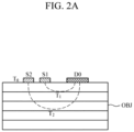
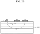
- FIGS. 2A and 2B are diagrams illustrating a configuration of a sensor according to the embodiment of FIG. 1 .
- FIG. 2C is a diagram illustrating a change in water absorption spectrum according to a temperature change.
- an apparatus 100 for estimating body temperature includes a sensor 110 and a processor 120.
- the sensor 110 may obtain spectra in two or more different light paths.
- the sensor 110 may include one or more light sources that emit light onto an object, and one or more detectors that detect light which returns after reacting with tissue of the object by being scattered or reflected from the object.
- the sensor 110 may include a first combination of a single light source and a plurality of detectors that are disposed at different distances from the single light source, a second combination of a single detector and of a plurality of light sources that are disposed at different distances from the single detector, or a third combination of a plurality of light sources and a plurality of detectors that are disposed at different distances from the plurality of light sources.
- the light source may include a light emitting diode (LED), a laser diode (LD), a phosphor, etc., but is not limited thereto.
- the detector may include a photo diode, a photo transistor, etc., or may be a spectrometer or a waveguide and the like connected to an external spectrometer.
- the detector is not limited thereto, and may include a complementary metal-oxide semiconductor (CMOS) image sensor, a charge-coupled device (CCD) image sensor, and the like.
- CMOS complementary metal-oxide semiconductor
- CCD charge-coupled device
- the sensor 110 may include a light source array having light sources emitting light of different wavelengths to obtain spectra, and a single detector.
- light sources S1 and S2 may have a narrow light emission wavelength range (e.g., a light emission wavelength range less than a preset wavelength range) so as to split wavelengths, and the respective light sources S1 and S2 may have different light emission wavelength ranges which overlap a portion of a water absorption wavelength range.
- the sensor 110 may include one light source and one detector array, disposed at a distance from the light source, or a spectrometer connected to a light waveguide and the like. In this case, the detector array may have optical filters integrated therein and having different central wavelengths.
- FIG. 2A illustrates an example of one detector D0 and two light sources S1 and S2 which are disposed at different distances from the detector D.
- the two light sources S1 and S2 are illustrated for convenience of explanation, but the number of light sources is not limited thereto.
- FIG. 2B illustrates an example of one light source S0 and two detectors D1 and D2 disposed at different distances from the light source S0. In this example embodiment, the number of detectors is not limited thereto.
- the following description will be given with reference to the example of FIG. 2A .
- the light sources S1 and S2 may emit light of different wavelengths.
- the wavelengths of the light sources S1 and S2 may include a wavelength range in which water absorption spectrum may be measured.
- the detector D0 may obtain an absorption spectrum by detecting light scattered or reflected from the object OBJ after the light is emitted by the light sources S1 and S2.
- the detector D0 may detect a spectrum of a first light that travels in a first light path (hereinafter referred to as a "first spectrum”) by detecting the first light that is scattered or reflected by a first tissue underneath the outer skin of the object after being emitted from the first light source S1 and then traveling to the first tissue.
- the first light path may start from the first light source S1, pass through the first tissue, and end at the detector D0. Further, the detector may detect a spectrum of a second light that travels in a second light path (hereinafter referred to as a "second spectrum") by detecting the second light that is scattered or reflected by a second tissue underneath the outer skin of the object after being emitted from the second light source S2 and then traveling to the second issue.
- a second spectrum a spectrum of a second light that travels in a second light path
- at least one light path may pass through skin tissue located deeply below the surface of skin (e.g., dermis, or a tissue located at a position deeper than the dermis).
- the first tissue may be an epidermis and the second tissue may be a dermis or a hypodermis which is located deeper than the epidermis.
- the first tissue may be a dermis and the second tissue may be a hypodermis.
- T 0 in FIGS. 2A and 2B denotes a reference temperature.
- the reference temperature T 0 may refer to a surface temperature of the object.
- the surface temperature may be measured from the object using an external temperature sensor and the like, or may be a generally known surface temperature.
- the surface temperature is not limited thereto, and may be a pre-defined specific temperature, e.g., a general room temperature.
- T 1 denotes a mean temperature of the first light path (hereinafter referred to as a "first mean temperature”), and may be, for example, a mean temperature at a maximum penetration depth of the first light path.
- T 2 denotes a mean temperature of the second light path (hereinafter referred to as a "second mean temperature”), and may be, for example, a mean temperature at a maximum penetration depth of the second light path.
- FIG. 2C illustrates a water absorption spectrum according to a temperature change.
- a spectrum measured in a water absorption wavelength range at the reference temperature T 0 or a spectrum obtained by converting a spectrum measured at a specific temperature to a spectrum corresponding to the reference temperature T 0 , may be defined as a reference spectrum.
- the first spectrum and the second spectrum, obtained by the sensor 110 may have different effective light path lengths and penetration depths, and may be expressed as a line integral for the effective light paths, as represented by the following Equation 1.
- a 1 (T) and A 2 (T) denote the first spectrum and the second spectrum measured by the sensor 110.
- L 1 denotes an effective light path between the first light source S1 and the detector D0
- L 2 denotes an effective light path between the second light source S2 and the detector D0.
- T(s) denotes a temperature change function according to a position s in the light path
- ⁇ w ( T ( s )) denotes an absorption coefficient per unit length of water, and a value which varies according to the temperature change T with a position s in the light path
- ⁇ eff,w ( T 0 , T 1 ) denotes an effective absorption coefficient in the first light path
- ⁇ eff,w ( T 0 , T 2 ) denotes an effective absorption coefficient in the second light path.
- T 0 , T 1 , and T 2 denote the reference temperature, the first mean temperature, and the second mean temperature, respectively;
- T 0 , T 1 denotes a temperature interval from the reference temperature to the first mean temperature;
- T 0 , T 2 denotes a temperature interval from the reference temperature to the second mean temperature.
- the processor 120 may estimate body temperature of the object by using the first spectrum and the second spectrum having different path lengths and obtained by the sensor 110. For example, the processor 120 may normalize the first spectrum and the second spectrum obtained by the sensor 110. For example, the processor 120 may normalize a magnitude of the first spectrum and the second spectrum based on a light path of the reference spectrum. In this case, the processor 120 may normalize the magnitude of the first spectrum and the second spectrum by multiplying or dividing a pre-defined scaling factor. In addition, the processor 120 may obtain a pure water absorption spectrum by removing a substance (e.g., blood glucose, etc.) of the object from each spectrum. For example, an effect of a substance of the object may be removed by subtracting the substance of the object from each spectrum. In this case, a substance spectrum of the object may be a spectrum generally known for the substance, or may be a spectrum pre-obtained from a user by preprocessing.
- a substance spectrum of the object may be a spectrum generally known for the substance, or may be a spectrum
- the processor 120 may estimate a mean temperature for each path based on each of the normalized spectra and the reference spectrum, and may obtain a temperature slope that indicates a change of the estimated mean temperatures between the respective paths.
- the temperature slope between the respective paths may refer to an effective temperature difference between the first mean temperature of the first path and the second mean temperature of the second path.
- Equation 2 is an example of a function for obtaining the first mean temperature of the first path by using the reference spectrum and the normalized first absorption spectrum.
- the processor 120 may obtain the effective temperature difference, at which a curve of the first spectrum, measured in the temperature interval (T 0 , T 1 ) from the reference temperature T 0 to the first mean temperature T 1 , may overlap the reference spectrum.
- the processor 120 may estimate the mean temperature T 1 of the first path.
- a 0 (T 0 ) denotes the reference spectrum measured at the reference temperature T 0 ;
- a 1 pw ( T ) denotes the normalized first spectrum;
- ⁇ A 1 denotes a difference between the reference spectrum and the normalized first spectrum;
- d ⁇ w dT denotes a water absorption temperature coefficient, and may be a value pre-obtained by preprocessing;
- ⁇ T 1 denotes the effective temperature difference to be obtained for the first path.
- the mean temperature T 1 of the first path may be estimated by adding up the reference temperature T 0 and the effective temperature difference ⁇ T 1 .
- the difference ⁇ A 1 between the reference spectrum and the normalized first spectrum may be converted into a relationship between the water absorption temperature coefficient d ⁇ w dT and the effective temperature difference ⁇ T 1 .
- a "minimize" function is a function for outputting the effective temperature difference ⁇ T 1 , at which a value of the function is minimized.
- the processor 120 may obtain a mean temperature of the second path based on the reference spectrum and the normalized second spectrum. That is, the processor 120 may obtain the effective temperature difference, at which a curve of the second spectrum, measured in the temperature interval (T 0 , T 2 ) from the reference temperature T 0 to the second mean temperature T 2 , may overlap the reference spectrum. By adding up the reference temperature T 0 and the effective temperature difference, the processor 120 may estimate the mean temperature T 2 of the second path.
- the processor 120 may estimate a core body temperature T c of the object by using the obtained first mean temperature T 1 , second mean temperature T 2 , and reference temperature T 0 .
- the core body temperature T c may refer to the temperature of the body's internal organs, and may be different from the reference temperature T 0 of the object which is measured from the skin surface.
- the processor 120 may estimate the core body temperature T c of the object by using the following Equations 3 and 4.
- T c T s + K g ⁇ C ⁇ ⁇ T 2 ⁇ ⁇ T 1
- T s T 0 + ⁇ T 1
- T c denotes the core body temperature of the object to be obtained
- K g denotes a heat transfer coefficient of tissue of the object, and is a value pre-obtained by preprocessing
- C denotes a calibration constant, and is a value pre-obtained by preprocessing
- ⁇ T 1 denotes the effective temperature difference of the first path
- ⁇ T 2 denotes the effective temperature difference of the second path, in which ⁇ T 2 - ⁇ T 1 denotes a temperature slope between the first path and the second path.
- T s denotes the mean temperature of the reference path, which may be any one of the first light path and the second light path.
- the reference path may be the first light path which is the shortest path, in which the first mean temperature may be obtained by using Equation 4.
- the second mean temperature may be obtained by adding up the reference temperature and the effective temperature difference of the second path by using the above Equation 4.
- an accurate surface temperature of the object may not be known at the time of estimating the body temperature of the object, such that by estimating the body temperature based on a relative relationship between the first mean temperature at a position close to the surface and the second mean temperature at a relatively deep position, a change in environment factors affecting heat transfer, such as a change in external ambient temperature, humidity, air flow, and the like, may be minimized.
- FIG. 3 is a block diagram illustrating an apparatus for estimating body temperature according to another example embodiment.
- the apparatus 300 for estimating a core body temperature includes a sensor 310, a processor 320, a storage 330, an output interface 340, and a communication interface 350.
- the sensor 310 and the processor 320 may have substantially the same structure as the sensor 110 and the processor 120 shown in FIG. 1 , such that a detailed description thereof will be omitted.
- the storage 330 may store information related to estimating body temperature.
- the storage 330 may store spectra obtained by the sensor 310, processing results of the processor 320, e.g., the normalized spectra, the first mean temperature, the second mean temperature, and a final body temperature value.
- the storage 330 may store a body temperature estimation model, the reference temperature, the reference spectrum according to the reference temperature, user characteristic information, and the like.
- the user characteristic information may include a user's age, gender, health condition, and the like.
- the storage 330 may include at least one storage medium of a flash memory type memory, a hard disk type memory, a multimedia card micro type memory, a card type memory (e.g., an SD memory, an XD memory, etc.), a Random Access Memory (RAM), a Static Random Access Memory (SRAM), a Read Only Memory (ROM), an Electrically Erasable Programmable Read Only Memory (EEPROM), a Programmable Read Only Memory (PROM), a magnetic memory, a magnetic disk, and an optical disk, and the like, but is not limited thereto.
- a flash memory type memory e.g., an SD memory, an XD memory, etc.
- RAM Random Access Memory
- SRAM Static Random Access Memory
- ROM Read Only Memory
- EEPROM Electrically Erasable Programmable Read Only Memory
- PROM Programmable Read Only Memory
- magnetic memory a magnetic disk, and an optical disk, and the like, but is not limited thereto.
- the output interface 340 may provide the processing results of the processor 320 for a user. For example, the output interface 340 may display the mean temperature of each path, the estimated final temperature value, and the like on a display. In particular, if the estimated body temperature value falls outside a normal range, the output interface 340 may provide a user with warning information by changing color, line thickness, etc., or displaying the abnormal value along with a normal range, so that the user may easily recognize the abnormal value. Further, along with or without the visual output, the output interface 340 may provide the estimated body temperature value for the user in a non-visual manner by voice, vibrations, tactile sensation, and the like using an audio output module such as a speaker, or a haptic module and the like.
- an audio output module such as a speaker, or a haptic module and the like.
- the communication interface 350 may communicate with an external device to transmit and receive various data, related to estimating body temperature, to and from the external device.
- the external device may include an information processing device such as a smartphone, a tablet PC, a desktop computer, a laptop computer, and the like.
- the communication interface 350 may transmit a body temperature estimation result to the external device, such as a user's smartphone and the like, so that the user may manage and monitor the estimation result by using a device having a relatively high performance.
- the communication interface 350 may communicate with the external device by using various wired or wireless communication techniques, such as Bluetooth communication, Bluetooth Low Energy (BLE) communication, Near Field Communication (NFC), WLAN communication, Zigbee communication, Infrared Data Association (IrDA) communication, Wi-Fi Direct (WFD) communication, Ultra-Wideband (UWB) communication, Ant+ communication, WIFI communication, Radio Frequency Identification (RFID) communication, 3G communication, 4G communication, 5G communication, and the like.
- BLE Bluetooth Low Energy
- NFC Near Field Communication
- WLAN Zigbee communication
- IrDA Infrared Data Association
- Wi-Fi Direct (WFD) communication Wi-Fi Direct
- UWB Ultra-Wideband
- Ant+ communication Zigbee communication
- WIFI communication Radio Frequency Identification
- RFID Radio Frequency Identification
- FIG. 4 is a block diagram illustrating an apparatus for estimating body temperature according to yet another example embodiment.
- FIG. 5 is a diagram illustrating an example of a configuration of a sensor according to the example embodiment of the FIG. 4 .
- the apparatus 400 for estimating body temperature includes a first sensor 410, a processor 420, and a second sensor 430.
- the first sensor 410 and the processor 420 are the same as the sensor 110 and the processor 120 of the example embodiment of FIG. 1 , such that the following description will be focused on non-overlapping parts.
- the apparatus 400 for estimating body temperature may include the storage 330, the output interface 340, and the communication interface 350 of FIG. 3 .
- the first sensor 410 may include one light source S3 and one detector D3.
- a distance between the light source S3 and the detector D3 provides a light path penetrating into a skin depth, e.g., the dermis, or a deeper depth, at which temperature is to be estimated.
- the number of light sources and detectors is not limited thereto.
- the first sensor 410 may be implemented by a spectrometer.
- the second sensor 430 may measure the surface temperature T0 of the object while the first sensor 410 obtains a spectrum from the object OBJ.
- the second sensor 430 may be a contact temperature sensor, such as a resistance temperature detector, a thermocouple, a thermistor, or a thermistor.
- the second sensor 430 may be a non-contact temperature sensor, such as an infrared sensor.
- the second sensor 430 may be disposed between the light source S3 and the detector D3.
- the position of the temperature sensor is not particularly limited thereto.
- the processor 420 may estimate body temperature of the object based on the spectrum obtained by the first sensor 410 and the surface temperature measured by the second sensor 430.
- the processor 420 may perform normalization based on the reference spectrum, pre-measured at the surface temperature in the water absorption wavelength range, or a spectrum obtained by converting a spectrum, measured from water or skin at a specific temperature, into a spectrum corresponding to the surface temperature; and may estimate the mean temperature of the light path based on the reference spectrum and the spectrum normalized by using the above Equation 2. Further, the processor 420 may obtain a temperature slope that indicates a change between the surface temperature and the estimated mean temperature of the light path.
- the processor 420 may estimate a final body temperature value (e.g., a core body temperature value) by using the following Equation 5.
- T c T 0 + K g ⁇ C ⁇ ⁇ T 3
- T c denotes a final body temperature value of the object to be obtained
- K g denotes a heat transfer coefficient of tissue of the object, and is a value pre-obtained by preprocessing
- C denotes a calibration constant, and is a value pre-obtained by preprocessing
- T 0 denotes the surface temperature
- ⁇ T 3 denotes the effective temperature difference between the surface temperature and the mean temperature of the light path, i.e., a temperature slope between the surface and the light path.
- an accurate surface temperature of the object may be known at the time of estimating body temperature of the object, such that by estimating a final body temperature value using the temperature slope between the surface temperature of the object and temperature at a relatively deep position, accuracy in estimating body temperature may be improved.
- FIG. 6 is a flowchart illustrating a method of estimating body temperature according to an example embodiment.
- FIG. 6 is an example of a method of estimating body temperature which is performed by the apparatuses 100 and 300 for estimating body temperature according to the example embodiments of FIGS. 1 and 3 , which are described above in detail, and thus will be briefly described below in order to avoid redundancy.
- the apparatus for estimating body temperature may measure a plurality of spectra in a plurality of different light paths of an object in 610.
- the plurality of light paths may include a path passing through a depth adjacent to the surface of the object, and a path passing through the dermis or a deeper position of the object.
- the apparatus for estimating body temperature may obtain a temperature slope for each path in 620 by using the spectra obtained for the respective paths in 610.
- the apparatus for estimating body temperature may estimate a mean temperature of each path based on the reference spectrum, the normalized first spectrum, and the normalized second spectrum by using the above Equation 2, and may obtain the temperature slope between the respective paths by using the mean temperature of each path.
- the apparatus for estimating body temperature may estimate a final body temperature value based on the temperature slope between the respective paths in 630.
- the apparatus for estimating body temperature may estimate the body temperature of the object by using the temperature slope between the respective paths and the reference temperature.
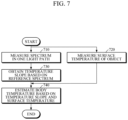
- FIG. 7 is a flowchart illustrating a method of estimating body temperature according to another example embodiment.
- FIG. 7 is an example of a method of estimating body temperature that is performed by the apparatus 400 for estimating body temperature according to the example embodiment of FIG. 4 , which will be briefly described below.
- the apparatus for estimating body temperature may first measure an absorption spectrum in one light path of the object in 710.
- the light path may include a path penetrating into a depth of the dermis or a deeper depth in the object.
- the apparatus for estimating body temperature may measure the surface temperature of the object during measurement of the spectrum from the object in 720.
- the apparatus for estimating body temperature may obtain a temperature slope between the surface temperature and a mean temperature of the light path in 730 by using the reference spectrum and the spectrum obtained in 710.
- the apparatus for estimating body temperature may estimate a final body temperature value based on the temperature slope and the surface temperature in 740.
- FIG. 8A is a block diagram illustrating a healthcare device according to an example embodiment.
- the healthcare device 800 may be manufactured as a separate device for measuring body temperature, or as an electronic device such as a smart watch, a smart band, smart glasses, smart earphones, a smart necklace, a smart ring, a smart patch, a smartphone, and the like.
- FIG. 8B is a diagram illustrating a smart watch, as an example of a structure of a healthcare device.
- the healthcare device is not limited thereto.
- the healthcare device 800 may include a function of estimating bio-information, as well as the aforementioned function of estimating body temperature.
- the bio-information may include triglyceride, body fat percentage, body water, blood glucose, cholesterol, carotenoid, protein, uric acid, blood pressure, vascular age, arterial stiffness, aortic pressure waveform, vascular compliance, stress index, fatigue level, skin age, skin elasticity, and the like.
- the healthcare device 800 in the form of a smart watch may include a main body MB and a strap ST.
- the main body MB may be formed in various shapes, and a battery may be embedded in the main body MB and/or the strap ST to supply power to various components of the healthcare device 800.
- the strap ST may be flexible so as to be wrapped around a user's wrist.
- the strap ST may be composed of a first strap and a second strap which are separated from each other. One ends of the first strap and the second strap are connected to both sides of the main body MB, and the other ends thereof may be connected to each other via a connecting means.
- the connecting means may be formed as magnetic connection, Velcro connection, pin connection, and the like, but is not limited thereto.
- the strap ST is not limited thereto, and may be integrally formed as a non-detachable band.
- the main body MB may include various components. As illustrated in FIG. 8A , a sensor 810, a processor 820, a display 830, a storage 840, and a communication interface 850 may be mounted in the main body MB. However, depending on the size and shape of a form factor and the like, some of the display 830, the storage 840, and the communication interface 850, and a temperature sensor 813 may be omitted.
- the sensor 810 may include two or more light sources 811 and at least one detector 812, or at least one light source 811 and two or more detectors 812, so as to have a plurality of different light paths.
- the sensor 810 may further include the temperature sensor 813 as illustrated herein, but the temperature sensor 813 may be omitted as needed.
- the sensor 810 may include one light source 811 and one detector 812 so as to have one light path.
- the light source may include a light emitting diode (LED), a laser diode (LD), a phosphor, etc., but is not limited thereto.
- the detector may include a photo diode, a photo transistor, and the like, or may include a spectrometer or a waveguide connected to an external spectrometer.
- the detector is not limited thereto, and may include a complementary metal-oxide semiconductor (CMOS) image sensor, a charge-coupled device (CCD) image sensor, and the like.
- CMOS complementary metal-oxide semiconductor
- CCD charge-coupled device
- the sensor 810 may be disposed on a rear surface of the main body MB so as to come into contact with an upper portion of a user's wrist when the main body MB is worn on the user's wrist.
- the processor 820 may be mounted in the main body MB and may be electrically connected to various components including the sensor 810. Upon receiving spectra of two or more different light paths from the sensor 810, the processor 820 may extract a reference temperature and a reference spectrum from the storage 840, and may estimate body temperature by using the plurality of spectra, the reference temperature, and the reference spectrum, as described above. In addition, upon receiving a spectrum of one light path and surface temperature from the sensor 810, the processor 820 may extract a reference spectrum, corresponding to the surface temperature, from the storage 840, and may estimate body temperature (e.g., core body temperature) by using the extracted surface temperature, the reference spectrum, and the spectrum of the light path.
- body temperature e.g., core body temperature
- the processor 820 may estimate bio-information by using an absorption spectrum received from the sensor 810.
- the processor 820 may estimate bio-information by using a bio-information estimation model which defines a correlation between absorbance of the absorption spectrum and bio-information.
- the bio-information estimation model may be pre-obtained during preprocessing by training based on deep learning, artificial intelligence, and the like.
- the processor 820 may estimate, for example, blood glucose, from the absorption spectrum by using Net Analyte Signal (NAS) analysis and the like. In this case, the processor 820 may correct the bio-information estimation model based on the reference spectrum at the surface temperature.
- NAS Net Analyte Signal
- the processor 820 may obtain a scattering coefficient based on the absorption spectrum, and may estimate, for example, triglyceride, based on the obtained scattering coefficient.
- a scattering coefficient based on the absorption spectrum
- the bio-information is not limited thereto and may be estimated based on the absorption spectrum by using various already known methods.
- the processor 820 may selectively perform any one of two or more healthcare modes. For example, the processor 820 may perform a first mode of estimating body temperature, a second mode of estimating bio-information, and a third mode of estimating both body temperature and bio-information. In the third mode, the processor 820 may estimate body temperature and bio-information simultaneously or sequentially. Any one of the first, second, and third modes may be set as a default mode. The default mode may be changed by a user. In this case, information for setting the default mode may be stored in the storage 840. The processor 820 may estimate body temperature and/or bio-information by performing a mode according to a user's request input through the display 830, the manipulator 860, and other input means, or by performing the preset default mode stored in the storage 840.
- the display 830 may be disposed on a front surface of the main body MB.
- the display 830 may include a display.
- the display may have a touch screen for receiving touch input.
- the display 830 may display a variety of functions performed by the processor 820, for example, guide information related to estimating body temperature and/or bio-information, and/or an estimation result.
- the storage 840 may store a variety of information required for performing various functions of the healthcare device 800.
- the storage 840 may include information related to estimating body temperature, such as the reference temperature, the reference spectrum, etc., information related to estimating bio-information such as a bio-information estimation model, etc., information related to user characteristics, and information such as an estimated body temperature value, an estimated bio-information value, and the like.
- the communication interface 850 may communicate with an external device, such as a user's smartphone, to transmit estimation results of body temperature and/or bio-information, or to receive information such as a user's request input through the external device, the reference spectra measured at various reference temperature values, the bio-information estimation model, and the like.
- an external device such as a user's smartphone
- the manipulator 860 may be formed on the crown of the side surface of the main body MB.
- the manipulator 860 may receive a user's command and may transmit the received command to the processor.
- the manipulator 860 may have a power button to turn on/off the wearable device 800.
- example embodiments can be embodied as computer-readable code on a computer-readable recording medium.
- the computer-readable recording medium is any data storage device that can store data that can be thereafter read by a computer system. Examples of the computer-readable recording medium include read-only memory (ROM), random-access memory (RAM), CD-ROMs, magnetic tapes, floppy disks, and optical data storage devices.
- the computer-readable recording medium can also be distributed over network-coupled computer systems so that the computer-readable code is stored and executed in a distributed fashion.
- an example embodiment may be written as a computer program transmitted over a computer-readable transmission medium, such as a carrier wave, and received and implemented in general-use or special-purpose digital computers that execute the programs.
- one or more units of the above-described apparatuses and devices can include circuitry, a processor, a microprocessor, etc., and may execute a computer program stored in a computer-readable medium.
Landscapes
- Health & Medical Sciences (AREA)
- Life Sciences & Earth Sciences (AREA)
- Physics & Mathematics (AREA)
- Engineering & Computer Science (AREA)
- Medical Informatics (AREA)
- Veterinary Medicine (AREA)
- Biomedical Technology (AREA)
- Heart & Thoracic Surgery (AREA)
- Biophysics (AREA)
- Molecular Biology (AREA)
- Surgery (AREA)
- Animal Behavior & Ethology (AREA)
- General Health & Medical Sciences (AREA)
- Public Health (AREA)
- Pathology (AREA)
- General Physics & Mathematics (AREA)
- Psychiatry (AREA)
- Spectroscopy & Molecular Physics (AREA)
- Cardiology (AREA)
- Physiology (AREA)
- Psychology (AREA)
- Dermatology (AREA)
- Optics & Photonics (AREA)
- Nuclear Medicine, Radiotherapy & Molecular Imaging (AREA)
- Child & Adolescent Psychology (AREA)
- Developmental Disabilities (AREA)
- Educational Technology (AREA)
- Hospice & Palliative Care (AREA)
- Emergency Medicine (AREA)
- Radiology & Medical Imaging (AREA)
- Social Psychology (AREA)
- Multimedia (AREA)
- Vascular Medicine (AREA)
- Artificial Intelligence (AREA)
- Computer Vision & Pattern Recognition (AREA)
- Signal Processing (AREA)
- Electromagnetism (AREA)
- Measuring And Recording Apparatus For Diagnosis (AREA)
Claims (15)
- Vorrichtung (100; 300; 400; 500) zum Schätzen der Körpertemperatur, wobei die Vorrichtung umfasst:einen Sensor (110; 310; 410; 810), der konfiguriert ist zum Erhalten von Spektren über eine Vielzahl von Lichtpfaden eines Objekts (OBJ), undeinen Prozessor (120; 320; 420; 820),dadurch gekennzeichnet, dass der Prozessor konfiguriert ist zum:Erhalten (620; 720) eines Temperaturgefälles zwischen Temperaturen, die der Vielzahl von Lichtpfaden entsprechen, basierend auf den Spektren der Vielzahl von Lichtpfaden und einem bei einer Referenztemperatur gemessenen Referenzspektrum, undSchätzen (630; 730) der Körpertemperatur des Objekts basierend auf dem Temperaturgefälle,wobei das Temperaturgefälle eine Änderung von durchschnittlichen Temperaturen zwischen den entsprechenden Pfaden ist.
- Vorrichtung (100; 300; 400; 500) nach Anspruch 1, wobei das Referenzspektrum unter Verwendung von Licht in einem Wasserabsorptionswellenlängenbereich gemessen wird.
- Vorrichtung (100; 300; 400; 500) nach Anspruch 1 oder 2, wobei der Sensor (110; 310; 410; 810) umfasst:eine Lichtquelle (S0; S1; S2), die konfiguriert ist zum Emittieren von Licht auf das Objekt (OBJ), undeinen Detektor (D0; D1; D2), der konfiguriert ist zum Erfassen des von dem Objekt gestreuten oder reflektierten Lichts, nachdem das Licht durch die Lichtquelle emittiert wurde.
- Vorrichtung (100; 300; 400; 500) nach einem der Ansprüche 1 bis 3, wobei wenigstens einer aus der Vielzahl von Lichtpfaden in eine Tiefe der Dermis oder eine andere Tiefe, die tiefer als die Tiefe der Dermis ist, eindringt.
- Vorrichtung (100; 300; 400; 500) nach einem der Ansprüche 1 bis 4, wobei der Prozessor (120; 320; 420; 820) weiterhin konfiguriert ist zum Normalisieren jeweils der Spektren der Vielzahl von Lichtpfaden basierend auf dem Referenzspektrum und zum Erhalten des Temperaturgefälles basierend auf den normalisierten Spektren der Vielzahl von Lichtpfaden, und
wobei der Prozessor weiterhin konfiguriert ist zum Schätzen einer durchschnittlichen Temperatur jedes aus der entsprechenden Vielzahl von Lichtpfaden basierend auf einer Differenz zwischen dem Referenzspektrum und den entsprechenden Spektren der Vielzahl von Lichtpfaden und zum Erhalten des Temperaturgefälles basierend auf jeder der geschätzten durchschnittlichen Temperaturen. - Vorrichtung (100; 300; 400; 500) nach einem der Ansprüche 1 bis 5, wobei der Prozessor (120; 320; 420; 820) weiterhin konfiguriert ist zum Schätzen der Körpertemperatur des Objekts (OBJ) basierend auf der Referenztemperatur und dem Temperaturgefälle unter Verwendung einer Körpertemperatur-Schätzgleichung.
- Vorrichtung (100; 300; 400, 500) nach Anspruch 6, wobei der Prozessor (120; 320; 420; 820) weiterhin konfiguriert ist zum:Schätzen einer durchschnittlichen Temperatur eines aus der Vielzahl von Lichtpfaden ausgewählten Referenzpfads, undSchätzen der Körpertemperatur des Objekts basierend auf dem Temperaturgefälle und der durchschnittlichen Temperatur des Referenzpfads unter Verwendung der Körpertemperatur-Schätzgleichung.
- Vorrichtung (100; 300; 400; 500) nach Anspruch 7, wobei der Prozessor (120; 320; 420; 820) weiterhin konfiguriert ist zum Bestimmen eines kürzesten Lichtpfads innerhalb der Vielzahl von Lichtpfaden als des Referenzpfads.
- Vorrichtung (100; 300; 400; 500) nach einem der Ansprüche 1 bis 8, der weiterhin eine Ausgabeschnittstelle (340) umfasst, die konfiguriert ist zum Ausgeben der geschätzten Körpertemperatur des Objekts (OBJ).
- Verfahren zum Schätzen der Körpertemperatur, wobei das Verfahren umfasst:Erhalten eines Spektrums über einen Lichtpfad, der durch ein Gewebe unterhalb einer Oberfläche eines Objekts (OBJ) hindurch geht,Messen einer Oberflächentemperatur von der Oberfläche des Objekts,dadurch gekennzeichnet, dass das Verfahren weiterhin umfasst:Erhalten eines Temperaturgefälles zwischen einer Temperatur in Entsprechung zu dem erhaltenen Spektrum und der Oberflächentemperatur basierend auf dem erhaltenen Spektrum und einem Referenzspektrum in Entsprechung zu der Oberflächentemperatur, undSchätzen der Körpertemperatur des Objekts basierend auf dem Temperaturgefälle,wobei das Temperaturgefälle eine Änderung von durchschnittlichen Temperaturen zwischen den entsprechenden Pfaden ist.
- Verfahren nach Anspruch 10, das weiterhin das Normalisieren des über den Lichtpfad erhaltenen Spektrums basierend auf einem Referenzspektrum in Entsprechung zu der Oberflächentemperatur und das Erhalten des Temperaturgefälles basierend auf dem normalisierten Spektrum umfasst.
- Verfahren nach Anspruch 11, das weiterhin das Schätzen einer durchschnittlichen Temperatur des Lichtpfads basierend auf einer Differenz zwischen dem Referenzspektrum und dem normalisierten Spektrum und das Erhalten des Temperaturgefälles basierend auf der Oberflächentemperatur und der durchschnittlichen Temperatur umfasst.
- Verfahren nach einem der Ansprüche 10 bis 12, das weiterhin das Schätzen der Körpertemperatur des Objekts basierend auf der Oberflächentemperatur und dem Temperaturgefälle unter Verwendung einer Körpertemperatur-Schätzgleichung umfasst.
- Gesundheitspflegeeinrichtung (800), umfassend:einen Hauptkörper (MB), der die Vorrichtung gemäß den Ansprüchen 1 bis 9 enthält, undeine Anzeige (830), die an dem Hauptkörper montiert ist,wobei der Prozessor (120; 320; 420; 820) weiterhin konfiguriert ist zum Durchführen eines ersten Modus zum Schätzen der Körpertemperatur des Objekts, eines zweiten Modus zu Schätzen von Bioinformationen basierend auf den erhaltenen Spektren und/oder eines dritten Modus zum Schätzen der Körpertemperatur und von Bioinformationen und zum Steuern der Anzeige für das Anzeigen eines Ergebnisses des Durchführens des ersten Modus, des zweiten Modus und/oder des dritten Modus.
- Gesundheitspflegeeinrichtung (800) nach Anspruch 14, wobei die Gesundheitspflegeeinrichtung eine intelligente Uhr, ein intelligentes Band, eine intelligente Brille, ein intelligenter Kopfhörer, ein intelligenter Ring, ein intelligentes Pflaster, ein intelligentes Halsband oder ein Smartphone ist, oder
wobei die Bioinformationen eines oder mehrere von Triglyceride, Körperfettanteil, Körperwasser, Blutzucker, Cholesterin, Carotinoid, Protein, Harnsäure, Blutdruck, vaskuläres Alter, arterielle Steifigkeit, Aortendruckwellenform, vaskuläre Compliance, Stressindex, Ermüdungsgrad, Hautalter und Hautelastizität umfassen.
Applications Claiming Priority (1)
| Application Number | Priority Date | Filing Date | Title |
|---|---|---|---|
| KR1020200157717A KR20220070792A (ko) | 2020-11-23 | 2020-11-23 | 체온 추정 장치 및 방법과, 헬스케어 기기 |
Publications (2)
| Publication Number | Publication Date |
|---|---|
| EP4001871A1 EP4001871A1 (de) | 2022-05-25 |
| EP4001871B1 true EP4001871B1 (de) | 2023-11-29 |
Family
ID=77264965
Family Applications (1)
| Application Number | Title | Priority Date | Filing Date |
|---|---|---|---|
| EP21190304.2A Active EP4001871B1 (de) | 2020-11-23 | 2021-08-09 | Vorrichtung und verfahren zur schätzung der körpertemperatur sowie eine gesundheitspflegevorrichtung |
Country Status (4)
| Country | Link |
|---|---|
| US (2) | US11717171B2 (de) |
| EP (1) | EP4001871B1 (de) |
| KR (1) | KR20220070792A (de) |
| CN (1) | CN114526830A (de) |
Families Citing this family (3)
| Publication number | Priority date | Publication date | Assignee | Title |
|---|---|---|---|---|
| JP7502737B2 (ja) * | 2020-08-27 | 2024-06-19 | 株式会社ユタカ電子製作所 | 見守り支援システムおよび見守り支援方法 |
| US20240159595A1 (en) * | 2021-03-10 | 2024-05-16 | Nippon Telegraph And Telephone Corporation | Temperature estimation method, temperature estimation program and temperature estimation device |
| AU2024343735A1 (en) | 2023-09-21 | 2026-05-07 | Samsung Electronics Co., Ltd. | Wearable electronic device for obtaining biometric information |
Family Cites Families (24)
| Publication number | Priority date | Publication date | Assignee | Title |
|---|---|---|---|---|
| US6998247B2 (en) | 2002-03-08 | 2006-02-14 | Sensys Medical, Inc. | Method and apparatus using alternative site glucose determinations to calibrate and maintain noninvasive and implantable analyzers |
| US7459713B2 (en) | 2003-08-14 | 2008-12-02 | Microptix Technologies, Llc | Integrated sensing system approach for handheld spectral measurements having a disposable sample handling apparatus |
| US7460895B2 (en) | 2005-01-24 | 2008-12-02 | University Of Iowa Research Foundation | Method for generating a net analyte signal calibration model and uses thereof |
| US7873397B2 (en) | 2007-06-19 | 2011-01-18 | Richard Higgins | Spectroscopic optical system |
| US7734321B2 (en) | 2007-07-13 | 2010-06-08 | All Protect, Llc | Apparatus for non-invasive spectroscopic measurement of analytes, and method of using the same |
| DE102008006245A1 (de) * | 2008-01-25 | 2009-07-30 | Nirlus Engineering Ag | Verfahren zur nichtinvasiven, optischen Bestimmung der Temperatur eines Mediums |
| US10949677B2 (en) | 2011-03-29 | 2021-03-16 | Thermal Matrix USA, Inc. | Method and system for detecting concealed objects using handheld thermal imager |
| JP5964773B2 (ja) | 2013-03-22 | 2016-08-03 | 日本電信電話株式会社 | 温度測定方法および装置 |
| JP6606082B2 (ja) | 2014-09-05 | 2019-11-13 | Phcホールディングス株式会社 | グルコース濃度の定量方法及びグルコース濃度測定装置 |
| JP2016075625A (ja) | 2014-10-08 | 2016-05-12 | セイコーエプソン株式会社 | 検量線作成装置、目的成分検量装置、及び、電子機器 |
| GB201511574D0 (en) * | 2015-07-01 | 2015-08-12 | Stfc Science & Technology | Clinical thermometer |
| US20170319066A1 (en) * | 2016-05-05 | 2017-11-09 | Morelight Technologies, Inc. | Method and apparatus for measuring body core temperature and core to skin temperature gradients |
| KR102610590B1 (ko) * | 2016-07-25 | 2023-12-07 | 삼성전자주식회사 | 생체 내 물질 추정 장치 및 방법, 단위 스펙트럼 획득 장치 및 웨어러블 기기 |
| JP2018021833A (ja) | 2016-08-04 | 2018-02-08 | セイコーエプソン株式会社 | 温度測定装置および温度測定方法 |
| KR102638309B1 (ko) | 2016-10-26 | 2024-02-19 | 삼성전자주식회사 | 웨어러블 장치 및 헬스 모니터링 방법 |
| WO2018082991A1 (en) | 2016-11-01 | 2018-05-11 | Koninklijke Philips N.V. | Device, system and method for determining the core body temperature of a subject |
| KR102655737B1 (ko) | 2016-11-30 | 2024-04-05 | 삼성전자주식회사 | 생체 성분 추정 장치 및 방법 |
| US11744469B2 (en) | 2017-03-31 | 2023-09-05 | Nec Corporation | Thermal diffusion coefficient measuring device, and deep-body thermometer, deep-body temperature measuring device, and deep-body temperature measuring method using same |
| KR102539144B1 (ko) | 2017-10-19 | 2023-06-01 | 삼성전자주식회사 | 개인화된 단위 스펙트럼 획득 장치 및 방법과, 생체 성분 추정 장치 및 방법 |
| KR102498121B1 (ko) * | 2017-11-20 | 2023-02-09 | 삼성전자주식회사 | 생체정보 추정 장치 및 방법 |
| JP6999385B2 (ja) | 2017-11-30 | 2022-01-18 | 株式会社テクノ・コモンズ | 物体のデータ測定装置 |
| KR102627146B1 (ko) | 2018-07-20 | 2024-01-18 | 삼성전자주식회사 | 스펙트럼 처리 장치 및 방법 |
| KR102638310B1 (ko) | 2018-10-04 | 2024-02-19 | 삼성전자주식회사 | 분석 물질의 농도 추정 장치 및 방법 |
| KR102669993B1 (ko) | 2018-10-17 | 2024-05-27 | 삼성전자주식회사 | 대상체의 온도 변화에 따른 스펙트럼 처리 장치 및 방법 |
-
2020
- 2020-11-23 KR KR1020200157717A patent/KR20220070792A/ko active Pending
-
2021
- 2021-03-30 US US17/217,481 patent/US11717171B2/en active Active
- 2021-05-10 CN CN202110505626.8A patent/CN114526830A/zh active Pending
- 2021-08-09 EP EP21190304.2A patent/EP4001871B1/de active Active
-
2022
- 2022-10-17 US US17/967,541 patent/US11925438B2/en active Active
Also Published As
| Publication number | Publication date |
|---|---|
| US20230034618A1 (en) | 2023-02-02 |
| US20220160239A1 (en) | 2022-05-26 |
| KR20220070792A (ko) | 2022-05-31 |
| CN114526830A (zh) | 2022-05-24 |
| US11717171B2 (en) | 2023-08-08 |
| US11925438B2 (en) | 2024-03-12 |
| EP4001871A1 (de) | 2022-05-25 |
Similar Documents
| Publication | Publication Date | Title |
|---|---|---|
| US11617523B2 (en) | Apparatus and method for estimating biological component | |
| US11925438B2 (en) | Apparatus and method for estimating body temperature, and healthcare device | |
| US11197632B2 (en) | Apparatus and method for estimating skin condition | |
| KR102693439B1 (ko) | 스펙트럼 측정 장치, 스펙트럼의 광원 온도 변화 보정 방법, 농도 추정 장치 및 방법 | |
| US20230009905A1 (en) | Apparatus and method for estimating biological information | |
| KR20190043967A (ko) | 개인화된 단위 스펙트럼 획득 장치 및 방법과, 생체 성분 추정 장치 및 방법 | |
| KR20220026207A (ko) | 체온 측정 장치 및 방법과, 헬스케어 기기 | |
| US10753797B2 (en) | Spectrum processing apparatus and spectrum processing method | |
| US20200261003A1 (en) | Apparatus and method for estimating analyte concentration | |
| US20200129095A1 (en) | Apparatus and method for estimating biological component | |
| KR102638310B1 (ko) | 분석 물질의 농도 추정 장치 및 방법 | |
| US11287374B2 (en) | Apparatus and method for updating bioinformation estimation model | |
| US11911157B2 (en) | Apparatus and method for estimating target component | |
| EP3792675B1 (de) | Linse, lichtquellenvorrichtung mit linse und vorrichtung zur bestimmung der konzentration eines analyten | |
| US20220104776A1 (en) | Apparatus and method for estimating bio-information, and method of optimizing bio-information estimation model based on temperature variation characteristic | |
| US12171584B2 (en) | Apparatus and method for estimating body component | |
| KR102786800B1 (ko) | 생체 정보 추정 모델의 유효성 판단 장치 및 방법 | |
| KR102919400B1 (ko) | 대상 신호 스펙트럼 획득 장치 및 방법 |
Legal Events
| Date | Code | Title | Description |
|---|---|---|---|
| PUAI | Public reference made under article 153(3) epc to a published international application that has entered the european phase |
Free format text: ORIGINAL CODE: 0009012 |
|
| STAA | Information on the status of an ep patent application or granted ep patent |
Free format text: STATUS: THE APPLICATION HAS BEEN PUBLISHED |
|
| AK | Designated contracting states |
Kind code of ref document: A1 Designated state(s): AL AT BE BG CH CY CZ DE DK EE ES FI FR GB GR HR HU IE IS IT LI LT LU LV MC MK MT NL NO PL PT RO RS SE SI SK SM TR |
|
| STAA | Information on the status of an ep patent application or granted ep patent |
Free format text: STATUS: REQUEST FOR EXAMINATION WAS MADE |
|
| 17P | Request for examination filed |
Effective date: 20221124 |
|
| RBV | Designated contracting states (corrected) |
Designated state(s): AL AT BE BG CH CY CZ DE DK EE ES FI FR GB GR HR HU IE IS IT LI LT LU LV MC MK MT NL NO PL PT RO RS SE SI SK SM TR |
|
| P01 | Opt-out of the competence of the unified patent court (upc) registered |
Effective date: 20230520 |
|
| REG | Reference to a national code |
Ref country code: DE Ref legal event code: R079 Free format text: PREVIOUS MAIN CLASS: G01K0007420000 Ipc: A61B0005021000 Ref country code: DE Ref legal event code: R079 Ref document number: 602021007227 Country of ref document: DE Free format text: PREVIOUS MAIN CLASS: G01K0007420000 Ipc: A61B0005021000 |
|
| GRAP | Despatch of communication of intention to grant a patent |
Free format text: ORIGINAL CODE: EPIDOSNIGR1 |
|
| STAA | Information on the status of an ep patent application or granted ep patent |
Free format text: STATUS: GRANT OF PATENT IS INTENDED |
|
| RIC1 | Information provided on ipc code assigned before grant |
Ipc: G01K 13/20 20210101ALI20230725BHEP Ipc: A61B 5/00 20060101ALI20230725BHEP Ipc: A61B 5/01 20060101ALI20230725BHEP Ipc: G01K 7/42 20060101ALI20230725BHEP Ipc: G01K 11/12 20210101ALI20230725BHEP Ipc: A61B 5/145 20060101ALI20230725BHEP Ipc: A61B 5/021 20060101AFI20230725BHEP |
|
| INTG | Intention to grant announced |
Effective date: 20230821 |
|
| GRAS | Grant fee paid |
Free format text: ORIGINAL CODE: EPIDOSNIGR3 |
|
| GRAA | (expected) grant |
Free format text: ORIGINAL CODE: 0009210 |
|
| STAA | Information on the status of an ep patent application or granted ep patent |
Free format text: STATUS: THE PATENT HAS BEEN GRANTED |
|
| AK | Designated contracting states |
Kind code of ref document: B1 Designated state(s): AL AT BE BG CH CY CZ DE DK EE ES FI FR GB GR HR HU IE IS IT LI LT LU LV MC MK MT NL NO PL PT RO RS SE SI SK SM TR |
|
| REG | Reference to a national code |
Ref country code: GB Ref legal event code: FG4D |
|
| REG | Reference to a national code |
Ref country code: CH Ref legal event code: EP |
|
| REG | Reference to a national code |
Ref country code: DE Ref legal event code: R096 Ref document number: 602021007227 Country of ref document: DE |
|
| REG | Reference to a national code |
Ref country code: IE Ref legal event code: FG4D |
|
| REG | Reference to a national code |
Ref country code: LT Ref legal event code: MG9D |
|
| REG | Reference to a national code |
Ref country code: NL Ref legal event code: MP Effective date: 20231129 |
|
| PG25 | Lapsed in a contracting state [announced via postgrant information from national office to epo] |
Ref country code: GR Free format text: LAPSE BECAUSE OF FAILURE TO SUBMIT A TRANSLATION OF THE DESCRIPTION OR TO PAY THE FEE WITHIN THE PRESCRIBED TIME-LIMIT Effective date: 20240301 |
|
| PG25 | Lapsed in a contracting state [announced via postgrant information from national office to epo] |
Ref country code: IS Free format text: LAPSE BECAUSE OF FAILURE TO SUBMIT A TRANSLATION OF THE DESCRIPTION OR TO PAY THE FEE WITHIN THE PRESCRIBED TIME-LIMIT Effective date: 20240329 |
|
| PG25 | Lapsed in a contracting state [announced via postgrant information from national office to epo] |
Ref country code: LT Free format text: LAPSE BECAUSE OF FAILURE TO SUBMIT A TRANSLATION OF THE DESCRIPTION OR TO PAY THE FEE WITHIN THE PRESCRIBED TIME-LIMIT Effective date: 20231129 |
|
| PG25 | Lapsed in a contracting state [announced via postgrant information from national office to epo] |
Ref country code: ES Free format text: LAPSE BECAUSE OF FAILURE TO SUBMIT A TRANSLATION OF THE DESCRIPTION OR TO PAY THE FEE WITHIN THE PRESCRIBED TIME-LIMIT Effective date: 20231129 |
|
| PG25 | Lapsed in a contracting state [announced via postgrant information from national office to epo] |
Ref country code: LT Free format text: LAPSE BECAUSE OF FAILURE TO SUBMIT A TRANSLATION OF THE DESCRIPTION OR TO PAY THE FEE WITHIN THE PRESCRIBED TIME-LIMIT Effective date: 20231129 Ref country code: IS Free format text: LAPSE BECAUSE OF FAILURE TO SUBMIT A TRANSLATION OF THE DESCRIPTION OR TO PAY THE FEE WITHIN THE PRESCRIBED TIME-LIMIT Effective date: 20240329 Ref country code: GR Free format text: LAPSE BECAUSE OF FAILURE TO SUBMIT A TRANSLATION OF THE DESCRIPTION OR TO PAY THE FEE WITHIN THE PRESCRIBED TIME-LIMIT Effective date: 20240301 Ref country code: ES Free format text: LAPSE BECAUSE OF FAILURE TO SUBMIT A TRANSLATION OF THE DESCRIPTION OR TO PAY THE FEE WITHIN THE PRESCRIBED TIME-LIMIT Effective date: 20231129 Ref country code: BG Free format text: LAPSE BECAUSE OF FAILURE TO SUBMIT A TRANSLATION OF THE DESCRIPTION OR TO PAY THE FEE WITHIN THE PRESCRIBED TIME-LIMIT Effective date: 20240229 |
|
| REG | Reference to a national code |
Ref country code: AT Ref legal event code: MK05 Ref document number: 1635236 Country of ref document: AT Kind code of ref document: T Effective date: 20231129 |
|
| PG25 | Lapsed in a contracting state [announced via postgrant information from national office to epo] |
Ref country code: NL Free format text: LAPSE BECAUSE OF FAILURE TO SUBMIT A TRANSLATION OF THE DESCRIPTION OR TO PAY THE FEE WITHIN THE PRESCRIBED TIME-LIMIT Effective date: 20231129 |
|
| PG25 | Lapsed in a contracting state [announced via postgrant information from national office to epo] |
Ref country code: SE Free format text: LAPSE BECAUSE OF FAILURE TO SUBMIT A TRANSLATION OF THE DESCRIPTION OR TO PAY THE FEE WITHIN THE PRESCRIBED TIME-LIMIT Effective date: 20231129 Ref country code: RS Free format text: LAPSE BECAUSE OF FAILURE TO SUBMIT A TRANSLATION OF THE DESCRIPTION OR TO PAY THE FEE WITHIN THE PRESCRIBED TIME-LIMIT Effective date: 20231129 Ref country code: PL Free format text: LAPSE BECAUSE OF FAILURE TO SUBMIT A TRANSLATION OF THE DESCRIPTION OR TO PAY THE FEE WITHIN THE PRESCRIBED TIME-LIMIT Effective date: 20231129 Ref country code: NO Free format text: LAPSE BECAUSE OF FAILURE TO SUBMIT A TRANSLATION OF THE DESCRIPTION OR TO PAY THE FEE WITHIN THE PRESCRIBED TIME-LIMIT Effective date: 20240229 Ref country code: NL Free format text: LAPSE BECAUSE OF FAILURE TO SUBMIT A TRANSLATION OF THE DESCRIPTION OR TO PAY THE FEE WITHIN THE PRESCRIBED TIME-LIMIT Effective date: 20231129 Ref country code: LV Free format text: LAPSE BECAUSE OF FAILURE TO SUBMIT A TRANSLATION OF THE DESCRIPTION OR TO PAY THE FEE WITHIN THE PRESCRIBED TIME-LIMIT Effective date: 20231129 Ref country code: HR Free format text: LAPSE BECAUSE OF FAILURE TO SUBMIT A TRANSLATION OF THE DESCRIPTION OR TO PAY THE FEE WITHIN THE PRESCRIBED TIME-LIMIT Effective date: 20231129 |
|
| PG25 | Lapsed in a contracting state [announced via postgrant information from national office to epo] |
Ref country code: DK Free format text: LAPSE BECAUSE OF FAILURE TO SUBMIT A TRANSLATION OF THE DESCRIPTION OR TO PAY THE FEE WITHIN THE PRESCRIBED TIME-LIMIT Effective date: 20231129 |
|
| PG25 | Lapsed in a contracting state [announced via postgrant information from national office to epo] |
Ref country code: AT Free format text: LAPSE BECAUSE OF FAILURE TO SUBMIT A TRANSLATION OF THE DESCRIPTION OR TO PAY THE FEE WITHIN THE PRESCRIBED TIME-LIMIT Effective date: 20231129 Ref country code: CZ Free format text: LAPSE BECAUSE OF FAILURE TO SUBMIT A TRANSLATION OF THE DESCRIPTION OR TO PAY THE FEE WITHIN THE PRESCRIBED TIME-LIMIT Effective date: 20231129 |
|
| PG25 | Lapsed in a contracting state [announced via postgrant information from national office to epo] |
Ref country code: SK Free format text: LAPSE BECAUSE OF FAILURE TO SUBMIT A TRANSLATION OF THE DESCRIPTION OR TO PAY THE FEE WITHIN THE PRESCRIBED TIME-LIMIT Effective date: 20231129 |
|
| PG25 | Lapsed in a contracting state [announced via postgrant information from national office to epo] |
Ref country code: SM Free format text: LAPSE BECAUSE OF FAILURE TO SUBMIT A TRANSLATION OF THE DESCRIPTION OR TO PAY THE FEE WITHIN THE PRESCRIBED TIME-LIMIT Effective date: 20231129 Ref country code: SK Free format text: LAPSE BECAUSE OF FAILURE TO SUBMIT A TRANSLATION OF THE DESCRIPTION OR TO PAY THE FEE WITHIN THE PRESCRIBED TIME-LIMIT Effective date: 20231129 Ref country code: RO Free format text: LAPSE BECAUSE OF FAILURE TO SUBMIT A TRANSLATION OF THE DESCRIPTION OR TO PAY THE FEE WITHIN THE PRESCRIBED TIME-LIMIT Effective date: 20231129 Ref country code: IT Free format text: LAPSE BECAUSE OF FAILURE TO SUBMIT A TRANSLATION OF THE DESCRIPTION OR TO PAY THE FEE WITHIN THE PRESCRIBED TIME-LIMIT Effective date: 20231129 Ref country code: EE Free format text: LAPSE BECAUSE OF FAILURE TO SUBMIT A TRANSLATION OF THE DESCRIPTION OR TO PAY THE FEE WITHIN THE PRESCRIBED TIME-LIMIT Effective date: 20231129 Ref country code: DK Free format text: LAPSE BECAUSE OF FAILURE TO SUBMIT A TRANSLATION OF THE DESCRIPTION OR TO PAY THE FEE WITHIN THE PRESCRIBED TIME-LIMIT Effective date: 20231129 Ref country code: CZ Free format text: LAPSE BECAUSE OF FAILURE TO SUBMIT A TRANSLATION OF THE DESCRIPTION OR TO PAY THE FEE WITHIN THE PRESCRIBED TIME-LIMIT Effective date: 20231129 Ref country code: AT Free format text: LAPSE BECAUSE OF FAILURE TO SUBMIT A TRANSLATION OF THE DESCRIPTION OR TO PAY THE FEE WITHIN THE PRESCRIBED TIME-LIMIT Effective date: 20231129 |
|
| PG25 | Lapsed in a contracting state [announced via postgrant information from national office to epo] |
Ref country code: PT Free format text: LAPSE BECAUSE OF FAILURE TO SUBMIT A TRANSLATION OF THE DESCRIPTION OR TO PAY THE FEE WITHIN THE PRESCRIBED TIME-LIMIT Effective date: 20240401 |
|
| PG25 | Lapsed in a contracting state [announced via postgrant information from national office to epo] |
Ref country code: PT Free format text: LAPSE BECAUSE OF FAILURE TO SUBMIT A TRANSLATION OF THE DESCRIPTION OR TO PAY THE FEE WITHIN THE PRESCRIBED TIME-LIMIT Effective date: 20240401 |
|
| REG | Reference to a national code |
Ref country code: DE Ref legal event code: R097 Ref document number: 602021007227 Country of ref document: DE |
|
| PLBE | No opposition filed within time limit |
Free format text: ORIGINAL CODE: 0009261 |
|
| STAA | Information on the status of an ep patent application or granted ep patent |
Free format text: STATUS: NO OPPOSITION FILED WITHIN TIME LIMIT |
|
| PG25 | Lapsed in a contracting state [announced via postgrant information from national office to epo] |
Ref country code: SI Free format text: LAPSE BECAUSE OF FAILURE TO SUBMIT A TRANSLATION OF THE DESCRIPTION OR TO PAY THE FEE WITHIN THE PRESCRIBED TIME-LIMIT Effective date: 20231129 |
|
| PG25 | Lapsed in a contracting state [announced via postgrant information from national office to epo] |
Ref country code: SI Free format text: LAPSE BECAUSE OF FAILURE TO SUBMIT A TRANSLATION OF THE DESCRIPTION OR TO PAY THE FEE WITHIN THE PRESCRIBED TIME-LIMIT Effective date: 20231129 |
|
| 26N | No opposition filed |
Effective date: 20240830 |
|
| REG | Reference to a national code |
Ref country code: CH Ref legal event code: PL |
|
| PG25 | Lapsed in a contracting state [announced via postgrant information from national office to epo] |
Ref country code: LU Free format text: LAPSE BECAUSE OF NON-PAYMENT OF DUE FEES Effective date: 20240809 |
|
| PG25 | Lapsed in a contracting state [announced via postgrant information from national office to epo] |
Ref country code: CH Free format text: LAPSE BECAUSE OF NON-PAYMENT OF DUE FEES Effective date: 20240831 Ref country code: MC Free format text: LAPSE BECAUSE OF FAILURE TO SUBMIT A TRANSLATION OF THE DESCRIPTION OR TO PAY THE FEE WITHIN THE PRESCRIBED TIME-LIMIT Effective date: 20231129 |
|
| REG | Reference to a national code |
Ref country code: BE Ref legal event code: MM Effective date: 20240831 |
|
| PG25 | Lapsed in a contracting state [announced via postgrant information from national office to epo] |
Ref country code: BE Free format text: LAPSE BECAUSE OF NON-PAYMENT OF DUE FEES Effective date: 20240831 |
|
| PG25 | Lapsed in a contracting state [announced via postgrant information from national office to epo] |
Ref country code: IE Free format text: LAPSE BECAUSE OF NON-PAYMENT OF DUE FEES Effective date: 20240809 |
|
| PG25 | Lapsed in a contracting state [announced via postgrant information from national office to epo] |
Ref country code: FI Free format text: LAPSE BECAUSE OF FAILURE TO SUBMIT A TRANSLATION OF THE DESCRIPTION OR TO PAY THE FEE WITHIN THE PRESCRIBED TIME-LIMIT Effective date: 20231129 |
|
| PGFP | Annual fee paid to national office [announced via postgrant information from national office to epo] |
Ref country code: DE Payment date: 20250708 Year of fee payment: 5 |
|
| PGFP | Annual fee paid to national office [announced via postgrant information from national office to epo] |
Ref country code: GB Payment date: 20250710 Year of fee payment: 5 |
|
| PGFP | Annual fee paid to national office [announced via postgrant information from national office to epo] |
Ref country code: FR Payment date: 20250708 Year of fee payment: 5 |
|
| PG25 | Lapsed in a contracting state [announced via postgrant information from national office to epo] |
Ref country code: CY Free format text: LAPSE BECAUSE OF FAILURE TO SUBMIT A TRANSLATION OF THE DESCRIPTION OR TO PAY THE FEE WITHIN THE PRESCRIBED TIME-LIMIT; INVALID AB INITIO Effective date: 20210809 |
|
| PG25 | Lapsed in a contracting state [announced via postgrant information from national office to epo] |
Ref country code: HU Free format text: LAPSE BECAUSE OF FAILURE TO SUBMIT A TRANSLATION OF THE DESCRIPTION OR TO PAY THE FEE WITHIN THE PRESCRIBED TIME-LIMIT; INVALID AB INITIO Effective date: 20210809 |