EP4001764A1 - Fuel swirler for pressure fuel nozzles - Google Patents
Fuel swirler for pressure fuel nozzles Download PDFInfo
- Publication number
- EP4001764A1 EP4001764A1 EP21210269.3A EP21210269A EP4001764A1 EP 4001764 A1 EP4001764 A1 EP 4001764A1 EP 21210269 A EP21210269 A EP 21210269A EP 4001764 A1 EP4001764 A1 EP 4001764A1
- Authority
- EP
- European Patent Office
- Prior art keywords
- fuel
- swirler
- core
- channels
- internal bore
- Prior art date
- Legal status (The legal status is an assumption and is not a legal conclusion. Google has not performed a legal analysis and makes no representation as to the accuracy of the status listed.)
- Granted
Links
- 239000000446 fuel Substances 0.000 title claims abstract description 239
- 238000004891 communication Methods 0.000 claims abstract description 5
- 239000012530 fluid Substances 0.000 claims abstract description 5
- 230000007704 transition Effects 0.000 claims description 22
- 238000000034 method Methods 0.000 claims description 18
- 238000011144 upstream manufacturing Methods 0.000 claims description 10
- 239000000853 adhesive Substances 0.000 claims description 6
- 230000001070 adhesive effect Effects 0.000 claims description 6
- 238000005219 brazing Methods 0.000 claims description 3
- PCHJSUWPFVWCPO-UHFFFAOYSA-N gold Chemical compound [Au] PCHJSUWPFVWCPO-UHFFFAOYSA-N 0.000 claims description 3
- 239000010931 gold Substances 0.000 claims description 3
- 229910052737 gold Inorganic materials 0.000 claims description 3
- 150000001875 compounds Chemical class 0.000 claims 1
- 230000009969 flowable effect Effects 0.000 claims 1
- 238000012544 monitoring process Methods 0.000 claims 1
- 239000007789 gas Substances 0.000 description 11
- 239000000203 mixture Substances 0.000 description 7
- 238000004519 manufacturing process Methods 0.000 description 6
- 238000005452 bending Methods 0.000 description 3
- 230000007423 decrease Effects 0.000 description 3
- 238000005516 engineering process Methods 0.000 description 3
- 238000003780 insertion Methods 0.000 description 3
- 230000037431 insertion Effects 0.000 description 3
- 238000009413 insulation Methods 0.000 description 3
- 230000008569 process Effects 0.000 description 3
- 230000004323 axial length Effects 0.000 description 2
- 238000001816 cooling Methods 0.000 description 2
- 230000000694 effects Effects 0.000 description 2
- 238000012986 modification Methods 0.000 description 2
- 230000004048 modification Effects 0.000 description 2
- 238000003466 welding Methods 0.000 description 2
- 230000001154 acute effect Effects 0.000 description 1
- 239000000654 additive Substances 0.000 description 1
- 230000000996 additive effect Effects 0.000 description 1
- 230000004888 barrier function Effects 0.000 description 1
- 230000000903 blocking effect Effects 0.000 description 1
- 238000002485 combustion reaction Methods 0.000 description 1
- 230000003247 decreasing effect Effects 0.000 description 1
- 238000009826 distribution Methods 0.000 description 1
- 238000001746 injection moulding Methods 0.000 description 1
- 239000002184 metal Substances 0.000 description 1
- 229910052751 metal Inorganic materials 0.000 description 1
- 238000002156 mixing Methods 0.000 description 1
- 238000003825 pressing Methods 0.000 description 1
- 230000009467 reduction Effects 0.000 description 1
- 238000012552 review Methods 0.000 description 1
- 238000000926 separation method Methods 0.000 description 1
- 239000007921 spray Substances 0.000 description 1
Images


Classifications
-
- F—MECHANICAL ENGINEERING; LIGHTING; HEATING; WEAPONS; BLASTING
- F23—COMBUSTION APPARATUS; COMBUSTION PROCESSES
- F23R—GENERATING COMBUSTION PRODUCTS OF HIGH PRESSURE OR HIGH VELOCITY, e.g. GAS-TURBINE COMBUSTION CHAMBERS
- F23R3/00—Continuous combustion chambers using liquid or gaseous fuel
- F23R3/28—Continuous combustion chambers using liquid or gaseous fuel characterised by the fuel supply
- F23R3/286—Continuous combustion chambers using liquid or gaseous fuel characterised by the fuel supply having fuel-air premixing devices
-
- B—PERFORMING OPERATIONS; TRANSPORTING
- B05—SPRAYING OR ATOMISING IN GENERAL; APPLYING FLUENT MATERIALS TO SURFACES, IN GENERAL
- B05B—SPRAYING APPARATUS; ATOMISING APPARATUS; NOZZLES
- B05B1/00—Nozzles, spray heads or other outlets, with or without auxiliary devices such as valves, heating means
- B05B1/34—Nozzles, spray heads or other outlets, with or without auxiliary devices such as valves, heating means designed to influence the nature of flow of the liquid or other fluent material, e.g. to produce swirl
- B05B1/3405—Nozzles, spray heads or other outlets, with or without auxiliary devices such as valves, heating means designed to influence the nature of flow of the liquid or other fluent material, e.g. to produce swirl to produce swirl
- B05B1/341—Nozzles, spray heads or other outlets, with or without auxiliary devices such as valves, heating means designed to influence the nature of flow of the liquid or other fluent material, e.g. to produce swirl to produce swirl before discharging the liquid or other fluent material, e.g. in a swirl chamber upstream the spray outlet
- B05B1/3421—Nozzles, spray heads or other outlets, with or without auxiliary devices such as valves, heating means designed to influence the nature of flow of the liquid or other fluent material, e.g. to produce swirl to produce swirl before discharging the liquid or other fluent material, e.g. in a swirl chamber upstream the spray outlet with channels emerging substantially tangentially in the swirl chamber
- B05B1/3431—Nozzles, spray heads or other outlets, with or without auxiliary devices such as valves, heating means designed to influence the nature of flow of the liquid or other fluent material, e.g. to produce swirl to produce swirl before discharging the liquid or other fluent material, e.g. in a swirl chamber upstream the spray outlet with channels emerging substantially tangentially in the swirl chamber the channels being formed at the interface of cooperating elements, e.g. by means of grooves
- B05B1/3442—Nozzles, spray heads or other outlets, with or without auxiliary devices such as valves, heating means designed to influence the nature of flow of the liquid or other fluent material, e.g. to produce swirl to produce swirl before discharging the liquid or other fluent material, e.g. in a swirl chamber upstream the spray outlet with channels emerging substantially tangentially in the swirl chamber the channels being formed at the interface of cooperating elements, e.g. by means of grooves the interface being a cone having the same axis as the outlet
-
- F—MECHANICAL ENGINEERING; LIGHTING; HEATING; WEAPONS; BLASTING
- F02—COMBUSTION ENGINES; HOT-GAS OR COMBUSTION-PRODUCT ENGINE PLANTS
- F02C—GAS-TURBINE PLANTS; AIR INTAKES FOR JET-PROPULSION PLANTS; CONTROLLING FUEL SUPPLY IN AIR-BREATHING JET-PROPULSION PLANTS
- F02C7/00—Features, components parts, details or accessories, not provided for in, or of interest apart form groups F02C1/00 - F02C6/00; Air intakes for jet-propulsion plants
- F02C7/22—Fuel supply systems
- F02C7/232—Fuel valves; Draining valves or systems
-
- F—MECHANICAL ENGINEERING; LIGHTING; HEATING; WEAPONS; BLASTING
- F23—COMBUSTION APPARATUS; COMBUSTION PROCESSES
- F23D—BURNERS
- F23D11/00—Burners using a direct spraying action of liquid droplets or vaporised liquid into the combustion space
- F23D11/36—Details, e.g. burner cooling means, noise reduction means
- F23D11/38—Nozzles; Cleaning devices therefor
- F23D11/383—Nozzles; Cleaning devices therefor with swirl means
-
- B—PERFORMING OPERATIONS; TRANSPORTING
- B05—SPRAYING OR ATOMISING IN GENERAL; APPLYING FLUENT MATERIALS TO SURFACES, IN GENERAL
- B05B—SPRAYING APPARATUS; ATOMISING APPARATUS; NOZZLES
- B05B7/00—Spraying apparatus for discharge of liquids or other fluent materials from two or more sources, e.g. of liquid and air, of powder and gas
- B05B7/02—Spray pistols; Apparatus for discharge
- B05B7/06—Spray pistols; Apparatus for discharge with at least one outlet orifice surrounding another approximately in the same plane
- B05B7/062—Spray pistols; Apparatus for discharge with at least one outlet orifice surrounding another approximately in the same plane with only one liquid outlet and at least one gas outlet
- B05B7/066—Spray pistols; Apparatus for discharge with at least one outlet orifice surrounding another approximately in the same plane with only one liquid outlet and at least one gas outlet with an inner liquid outlet surrounded by at least one annular gas outlet
-
- F—MECHANICAL ENGINEERING; LIGHTING; HEATING; WEAPONS; BLASTING
- F05—INDEXING SCHEMES RELATING TO ENGINES OR PUMPS IN VARIOUS SUBCLASSES OF CLASSES F01-F04
- F05D—INDEXING SCHEME FOR ASPECTS RELATING TO NON-POSITIVE-DISPLACEMENT MACHINES OR ENGINES, GAS-TURBINES OR JET-PROPULSION PLANTS
- F05D2220/00—Application
- F05D2220/30—Application in turbines
- F05D2220/32—Application in turbines in gas turbines
-
- F—MECHANICAL ENGINEERING; LIGHTING; HEATING; WEAPONS; BLASTING
- F05—INDEXING SCHEMES RELATING TO ENGINES OR PUMPS IN VARIOUS SUBCLASSES OF CLASSES F01-F04
- F05D—INDEXING SCHEME FOR ASPECTS RELATING TO NON-POSITIVE-DISPLACEMENT MACHINES OR ENGINES, GAS-TURBINES OR JET-PROPULSION PLANTS
- F05D2230/00—Manufacture
- F05D2230/60—Assembly methods
-
- F—MECHANICAL ENGINEERING; LIGHTING; HEATING; WEAPONS; BLASTING
- F05—INDEXING SCHEMES RELATING TO ENGINES OR PUMPS IN VARIOUS SUBCLASSES OF CLASSES F01-F04
- F05D—INDEXING SCHEME FOR ASPECTS RELATING TO NON-POSITIVE-DISPLACEMENT MACHINES OR ENGINES, GAS-TURBINES OR JET-PROPULSION PLANTS
- F05D2240/00—Components
- F05D2240/35—Combustors or associated equipment
Definitions
- the invention relates generally to gas turbine engines and, more particularly, to a fuel swirler for a fuel nozzle.
- Fuel nozzles are used for injecting fuel and air mixtures into the combustors of gas turbine engines.
- Compressed fuel is typically fed under pressure into a fuel nozzle and a surrounding array of pressurized air flow channels is provided to form an atomized air/fuel mixture.
- the fuel nozzles may comprises a fuel swirler assembled from a swirler housing with an interior chamber and a swirler core that is press fit into the interior chamber of the swirler housing.
- the combined configuration of control surfaces between the swirler housing and swirler core define fuel flow channels and shaped surfaces. These channels and surfaces may control the direction, pressure and kinetic energy of the pressurized fuel flow to achieve a desired set of parameters for the fuel spray exiting the fuel outlet orifice.
- the fuel typically travels through channels or grooves between the swirler core and the swirler housing.
- the proximity of the fuel to the outer surface of the fuel swirler may lead to undesirably high fuel temperatures, which may lead to issues such as fuel choking and a potential reduction of the fuel nozzle's life expectancy.
- such typical swirler cores are often asymmetrically shaped to account for the outer fuel channels, for instance having features such as one or more flat portions on their exterior surface. This may lead to undesirable consequences such as bending and/or plastic deformation of the swirler core when inserted into the swirler housing, potentially blocking or restricting the flow of fuel through the channels or grooves.
- a fuel swirler for a gas turbine engine fuel nozzle, comprising: a swirler housing defining an interior chamber having a fuel outlet at a downstream end relative to a fuel flow direction through the fuel swirler; a swirler core mounted inside the interior chamber, the swirler core having a downstream end portion with one or more fuel channels disposed thereon, the one or more fuel channels in fluid communication with the fuel outlet, an internal bore extending longitudinally through the swirler core, the internal bore having an inlet connectable to a source of fuel, and one or more exit holes fluidly connecting the internal bore to the one or more fuel channels; and an annular air gap radially between the swirler housing and the swirler core for thermally shielding the internal bore.
- a fuel swirler for a gas turbine engine fuel nozzle comprising: a swirler housing defining an interior chamber extending from an opening at an upstream end relative to a fuel flow direction to a fuel outlet at a downstream end, the interior chamber defining a tapering transition portion axially disposed upstream of the fuel outlet and a socket portion upstream of the transition portion; and a swirler core receivable within the interior chamber of the swirler housing, the swirler core having a cylindrical shank portion and an end portion axially disposed downstream of the shank portion, the end portion having one or more fuel channels disposed thereon, the shank portion concentrically positionable within the socket portion and defining an air gap therebetween, the end portion engageable with the transition portion of the interior chamber, the swirler core defining an interior bore having a fuel inlet at an upstream end and one or more exit holes fluidly connecting the internal bore to the one or more fuel channels.
- a method of assembling a fuel swirler for a gas turbine engine the fuel swirler including a swirler housing and a swirler core, the method comprising: inserting an end of the swirler core into an interior chamber of the swirler housing, an annular air gap forming between the swirler core and the swirler housing; abutting the inserted end of the swirler core against a transition portion of the interior chamber adjacent a fuel outlet in the swirler housing, the fuel outlet in fluid communication with an axial fuel path extending through an internal bore of the swirler core and through one or more exit holes fluidly connecting the internal bore to one or more fuel channels disposed in the inserted end of the swirler core; modulating the depth of the inserted end of the swirler core based on a desired engagement level between the transition portion and the one or more fuel channels; and fixing the swirler core to the swirler housing.
- the end portion of the swirler core includes a frustoconical portion through which the one or more exit holes pass and a tapered abutting portion which the one or more fuel channels are disposed within.
- the one or more fuel channels include a number of fuel channels that is a multiple of a number of the one or more exit holes.
- a cross-sectional area of the internal bore is greater than a combined cross-sectional area of the one or more fuel channels.
- the internal bore is a central cylindrical bore axially disposed along a central axis of the swirler core.
- the swirler core is axisymmetric about the central axis thereof.
- FIG. 1 shows an axial cross-section through an example gas turbine engine. While FIG. 1 illustratively shows a turbo-fan type gas turbine engine, it is understood that the present disclosure is applicable to other types of gas turbine aircraft engines as well.
- air intake into the engine passes over fan blades 1 in a fan case 2 and is then split into an outer annular flow through the bypass duct 3 and an inner flow through the low-pressure axial compressor 4 and high-pressure centrifugal compressor 5.
- Compressed air exits the compressor 5 through a diffuser 6 and is contained within a plenum 7 that surrounds the combustor 8.
- Fuel is supplied to the combustor 8 through fuel tubes 9 and fuel is mixed with air from the plenum 7 when sprayed through nozzles into the combustor 8 as a fuel air mixture that is ignited.
- a portion of the compressed air within the plenum 7 is admitted into the combustor 8 through orifices in the side walls to create a cooling air curtain along the combustor walls or is used for cooling to eventually mix with the hot gases from the combustor 8 and pass over the nozzle guide vane 10 and turbines 11 before exiting the tail of the engine as exhaust.
- a fuel nozzle includes a concentric array of compressed air orifices to create a swirling air flow surrounding a central fuel injecting swirler. The resultant shear forces between air and fuel cause the fuel and air mix together and form an atomized fuel-air mixture for combustion.
- FIG. 2 shows an isometric cross-section view of an exemplary embodiment of a fuel swirler 12 for a fuel nozzle.
- the fuel swirler 12 comprises a swirler core 13 having an internal bore 14 extending longitudinally through the swirler core 13 along a longitudinal axis L through which fuel is transported as will be discussed in further detail below.
- the internal bore 14 is a central bore coaxial to the centerline of the swirler core.
- the swirler core 13 is axially mounted inside an interior chamber 15 of a swirler housing 16.
- the swirler core 13 is axially insertable through an opening 17 in the swirler housing 16 at an upstream end U.E.
- the interior chamber 15 includes a socket portion 19 downstream of the opening 17 and a transition portion 20 downstream of the socket portion 19 and upstream of the fuel outlet 18.
- the outer surface of the swirler housing 16 is shaped to optimize the aerodynamic performance of the fuel swirler 12 in relation to the streams of compressed air while maintaining the required strength and structural integrity of the fuel swirler 12.
- the swirler core 13 has a generally cylindrical exterior surface and includes a shank portion 21 concentrically positionable within the socket portion 19 of the interior chamber 15.
- An annular air channel or air gap 22 is formed radially between the exterior surface of the swirler core 13 and the bounding wall of the interior chamber 15 of the swirler housing 16. This air gap 22 may extend, for instance along the axial length of the shank portion 21. Such an air gap 22 may provide an added layer of thermal insulation for the flow of fuel F travelling internally through the swirler core 13.
- the swirler core 13 and/or swirler housing 16 may be dimensioned to increase or decrease the thickness of the air gap 22 to vary the provided level of thermal insulation.
- Fuel may be provided to the internal bore 14 via a fuel inlet 23, receiving fuel from the fuel tubes 9. According to the illustrated embodiment, the fuel inlet 23 is provided at the upstream end of the swirler core 13 and is axially aligned with the internal bore 14.
- the swirler core 13 further includes a downstream end portion 24 abuttable against the wall of the transition portion 20 of the interior chamber 15.
- the level of engagement between the end portion 24 and the transition portion 20 may be chosen to meter or control the rate of fuel flow F exiting the fuel swirler 12 through fuel outlet 18.
- the end portion 24 includes a frustoconical portion 25 and a protruding tapered abutting portion 26 extending axially from the frustoconical portion 25.
- the frustoconical portion 25 begins to taper axially upstream of the transition portion 20 of the interior chamber 15, creating an annular fuel gallery 27.
- Fuel may exit the internal bore 14 of the swirler core 13 via one or more exit holes 28 disposed in the end portion 24, illustratively on the frustoconical portion 25.
- the exit holes 28 are fluidly connected to the fuel gallery 27 to direct the fuel passing through the internal bore 14 into the fuel gallery 27.
- the shown swirler core 13 includes three exit holes 28, it is understood that more or less exit holes 28 may be provided depending on the desired fuel flow.
- the shown exit holes 28 are circular, other shaped holes may be contemplated as well.
- the exit holes 28 are formed into the swirler core 13 at an acute angle with the longitudinal axis L, for instance by being drilled or otherwise machined. The angle at which the exit hole(s) 28 are formed may vary, for instance, to increase or decrease the swirling effect provided to the exiting fuel.
- the fuel swirler 12 further includes one or more spaced apart recessed fuel channels or slots 29 disposed in the end portion 24, illustratively on the abutting portion 26.
- the abutting portion 26 includes a frustoconical sidewall 30 and a flat end face 31.
- the fuel channel(s) 29 begin at an annular recessed portion 32 of the end portion 24, extend the axial length of the sidewall 30 and open at the end face 31.
- the fuel channels 29 cooperate with the wall of the swirler housing 16 circumscribing the transition portion 20 to define metering passages for metering the flow of fuel from the fuel gallery 27.
- Other configurations for the end portion 24 may be contemplated as well.
- Fuel exiting the internal bore 14 of the swirler core 13 through the exit hole(s) 28 is directed through the fuel channel(s) 29 towards the fuel outlet 18.
- the fuel travels through the one or more fuel channels 29 in a smaller, i.e. less voluminous, stream than in the internal bore 14, and as such is enabled to atomize into small droplets as it exits through the fuel outlet 18.
- the fuel exiting through the fuel outlet 18 in this atomized state, i.e. in small droplets, is combined with compressed air (not shown) and directed towards the combustor 8.
- three fuel channels 29 with square cross-sectional shapes are helically disposed about the abutting portion 26, although in other cases the number, cross-sectional shape and/or positioning about the abutting portion 26 may vary.
- the illustrated fuel channels 29 are helically disposed about the abutting portion 26, in other cases the fuel channel(s) 29 may be axially disposed about the abutting portion 26, i.e. parallel to the longitudinal axis L.
- the illustrated fuel channels 29 include square cross-sectional shapes, in other cases the cross-sectional shape of the fuel channel(s) 29 may be semi-circular or triangular. Other cross-sectional shapes may be contemplated as well.
- Fuel under pressure enters via the fuel inlet 23 into the internal bore 14 of the swirler core 13.
- the fuel exits the internal bore 14 via the exit hole(s) 28 and is directed via the fuel gallery 27 through the fuel channel(s) 29 disposed in the end portion 24 towards the fuel outlet 18 and out of the fuel swirler 12.
- An axial fuel path is thus defined between the fuel inlet 23 and the fuel outlet 18.
- the number of exit holes 28 corresponds to the number of fuel channels 29. In some cases, the number of fuel channels 29 is a multiple of the number of exit holes 28.
- the end portion 24 includes three exit holes 28 and three fuel channels 29, although other numbers of exit holes 28 and/or fuel channels 29 may be considered. In an alternate embodiment, for instance, the end portion 24 may include two exit holes 28 and four fuel channels 29. Other numbers of exit holes 28 and fuel channels 29 may be contemplated as well.
- the exit of the holes 28 can be placed such that the fuel directly feeds into the fuel channels 29, or feeds in between the channels 29 . In the exemplary embodiment shown in figure 4 , the exit of the holes 28 are circumferentially in-between the channels 29. That is the "clocking" of the exit holes 28 is different from that of the channels 29.
- the internal bore 14 is a central cylindrical bore along the longitudinal axis L through which fuel is transported, although other bore shapes and configurations may be contemplated as well.
- the internal bore 14 may be slightly offset from and parallel to the longitudinal axis L.
- the swirler core 13 may alternatively include two or more internal bores 14 to transport the fuel.
- the dimensions of the internal bore 14 and the exit hole(s) 28 are selected so that the flow of fuel through the swirler is metered by the fuel channel(s) 29.
- the swirler core 13 may be dimensioned so that the rate of fuel flow F through the internal bore 14 and the hole(s) 28 is greater than the allowable rate of fuel flow through the combined one or more fuel channel 29.
- the swirler core 13 may be dimensioned so that the cross-sectional area of the internal bore 14 is three times greater than the combined cross-sectional areas of the fuel channel(s) 29.
- each fuel channel 29 may allow a rate of fuel flow that is nine times less than the rate of fuel flow F through the internal bore 14.
- Other relative fuel flow rates may be contemplated as well.
- the cross-sectional area of the internal bore 14 is greater than the combined cross-sectional areas of the fuel channel(s) 29, the fuel channels 29 will be metering the flow of fuel F.
- fuel exiting the internal bore 14 via exit holes 28 may accumulate in the fuel gallery 27 before passing through the fuel channel(s) 29.
- the fuel swirler 12 may be assembled by inserting the swirler core 13 through the opening of the 17 of the swirler housing 16.
- the rate of fuel flow F may be controlled based on the depth of insertion of the swirler core 13 into the interior chamber 15 of the swirler housing 16.
- the fuel channel(s) 29 become increasingly covered or closed off due to the tapered profiles of the transition portion 20 and the frustoconical sidewall 30 of the abutting portion 26.
- the rate of fuel flow F may be controlled.
- the transition portion 20 and the frustoconical sidewall 30 may taper at different rates to alter the effect that the continued insertion of the swirler core 13 into the interior chamber 15 has on the rate of fuel flow F.
- the swirler core 13 is inserted into the interior chamber with the abutting portion 26 engaging the transition portion 20. Then, fuel is directed through the internal bore 14 via the fuel inlet 23, with the rate of fuel flow F exiting the fuel swirler 12 via the fuel outlet 18 is monitored, for instance via a flow meter (not shown). Then, the depth of the swirler core 13 within the interior chamber 15 is adjusted in either direction to modulate the exposed portion of the fuel channel(s) 29, i.e. the surface area through which fuel may exit from the fuel channel(s) 29, thus increasing or decreasing the rate of fuel flow F until a desired flow rate has been achieved. At such a point, the flow of fuel F may be stopped. As such, a desired level of engagement between the transition portion 20 and the abutting portion 26 may be selected to modulate the desired fuel flow rate. Other methods of achieving a desired fuel flow rate may be contemplated as well.
- the fuel channel(s) 29 may be manufactured into the end portion 24 with larger dimensions than required since their cross-sectional area is reduced as the swirler core 13 is inserted into the interior chamber 15. Such allowance may facilitate the overall manufacturing process of the fuel swirler, for instance by appeasing various manufacturing tolerances.
- the swirler core 13 is fixed to the swirler housing 16.
- the swirler core 13 and swirler housing 16 may be fixed together through a brazing process. For instance, a thin layer of gold paste (not shown) is applied to a shoulder 33 of the swirler core 13 before its insertion into the swirler housing 16.
- the fuel swirler 12 may be heated, for instance in a furnace, to solidify the gold paste into an adhesive. Such an adhesive may maintain the swirler core 13 at the previously-selected depth for a desired flow rate and affix the swirler core 13 and swirler housing 16 together, readying the fuel swirler 12 for use.
- Other methods of fixing the swirler core 13 to the swirler housing 16 may be contemplated as well, for instance through various welding processes.
- the interior chamber 15 of the swirler housing 16 includes a radially thicker portion 34, illustratively at the downstream end of the socket portion 19.
- This thicker portion 34 decreases the diameter of the interior chamber 15, adding a level of resistance when inserting the swirler core 13 into the interior chamber 15. This added resistance may facilitate the above-described method of metering the flow of fuel, for instance by offering more control of the depth of the swirler core 13 to the user.
- the thickness of the thicker portion 34 may be selected based on the desired level of resistance against the inserted swirler core 13, among other considerations.
- the thicker portion 34 may provide a barrier between the air gap 22 and the annular fuel gallery 27 when the swirler core 13 is inserted in the interior chamber 15, preventing the fuel in the fuel gallery 27 and the air in the air gap 22 from undesirably mixing.
- At least various portions of the swirler core 13 and/or swirler housing 16 are axisymmetric about the longitudinal axis L.
- the shank portion 21 of the swirler core 13 is axisymmetric about the longitudinal axis L.
- An axisymmetric swirler core 13 under axial force will have balanced compressive axial stresses radially across the uniform cross-sectional area of the swirler core 13. There is no force imbalance to create non-elastic bending, buckling or lateral distortion since the axisymmetric cross-section provides an axisymmetric distribution of stress.
- both the swirler core 13 and the swirler housing 16 are axisymmetric about the longitudinal axis L.
- the air gap 22 may be consistently maintained about the circumference of the swirler core 13. This provides a consistent layer of thermal insulation to the flow of fuel F throughout the internal bore 14, ensuring the fuel temperature is maintained at a low enough temperature based on the given engine's requirements.
- the temperature of the fuel is further reduced, which in some cases may extend the life expectancy of the fuel nozzle. For instance, in various cases the fuel nozzles in a given gas turbine engine are surrounded by various sources of heat, so the placement of the axial fuel path through the internal bore 14 of the swirler core 13 provides the greatest possible separation between the fuel and such sources of heat.
- any number of exit holes 28 in excess of one and fuel channels 29 in excess of one can be arranged in a circumferentially spaced apart array that results in an axisymmetric cross-section.
- FIG. 4 shows three exit holes 28 and three fuel channels 29, but two or more exit holes and/or two or more fuel channels 29 can be axisymmetrically distributed with reference to the longitudinal axis L in other manners as well.
Abstract
Description
- The invention relates generally to gas turbine engines and, more particularly, to a fuel swirler for a fuel nozzle.
- Fuel nozzles are used for injecting fuel and air mixtures into the combustors of gas turbine engines. Compressed fuel is typically fed under pressure into a fuel nozzle and a surrounding array of pressurized air flow channels is provided to form an atomized air/fuel mixture.
- The fuel nozzles may comprises a fuel swirler assembled from a swirler housing with an interior chamber and a swirler core that is press fit into the interior chamber of the swirler housing. The combined configuration of control surfaces between the swirler housing and swirler core define fuel flow channels and shaped surfaces. These channels and surfaces may control the direction, pressure and kinetic energy of the pressurized fuel flow to achieve a desired set of parameters for the fuel spray exiting the fuel outlet orifice.
- In such fuel swirlers, the fuel typically travels through channels or grooves between the swirler core and the swirler housing. The proximity of the fuel to the outer surface of the fuel swirler may lead to undesirably high fuel temperatures, which may lead to issues such as fuel choking and a potential reduction of the fuel nozzle's life expectancy.
- In addition, such typical swirler cores are often asymmetrically shaped to account for the outer fuel channels, for instance having features such as one or more flat portions on their exterior surface. This may lead to undesirable consequences such as bending and/or plastic deformation of the swirler core when inserted into the swirler housing, potentially blocking or restricting the flow of fuel through the channels or grooves.
- In one aspect, there is provided a fuel swirler for a gas turbine engine fuel nozzle, comprising: a swirler housing defining an interior chamber having a fuel outlet at a downstream end relative to a fuel flow direction through the fuel swirler; a swirler core mounted inside the interior chamber, the swirler core having a downstream end portion with one or more fuel channels disposed thereon, the one or more fuel channels in fluid communication with the fuel outlet, an internal bore extending longitudinally through the swirler core, the internal bore having an inlet connectable to a source of fuel, and one or more exit holes fluidly connecting the internal bore to the one or more fuel channels; and an annular air gap radially between the swirler housing and the swirler core for thermally shielding the internal bore.
- In another aspect, there is provided a fuel swirler for a gas turbine engine fuel nozzle, comprising: a swirler housing defining an interior chamber extending from an opening at an upstream end relative to a fuel flow direction to a fuel outlet at a downstream end, the interior chamber defining a tapering transition portion axially disposed upstream of the fuel outlet and a socket portion upstream of the transition portion; and a swirler core receivable within the interior chamber of the swirler housing, the swirler core having a cylindrical shank portion and an end portion axially disposed downstream of the shank portion, the end portion having one or more fuel channels disposed thereon, the shank portion concentrically positionable within the socket portion and defining an air gap therebetween, the end portion engageable with the transition portion of the interior chamber, the swirler core defining an interior bore having a fuel inlet at an upstream end and one or more exit holes fluidly connecting the internal bore to the one or more fuel channels.
- In a further aspect, there is provided a method of assembling a fuel swirler for a gas turbine engine, the fuel swirler including a swirler housing and a swirler core, the method comprising: inserting an end of the swirler core into an interior chamber of the swirler housing, an annular air gap forming between the swirler core and the swirler housing; abutting the inserted end of the swirler core against a transition portion of the interior chamber adjacent a fuel outlet in the swirler housing, the fuel outlet in fluid communication with an axial fuel path extending through an internal bore of the swirler core and through one or more exit holes fluidly connecting the internal bore to one or more fuel channels disposed in the inserted end of the swirler core; modulating the depth of the inserted end of the swirler core based on a desired engagement level between the transition portion and the one or more fuel channels; and fixing the swirler core to the swirler housing.
- Optionally, and in accordance with any of the above or as claimed in any claim, the end portion of the swirler core includes a frustoconical portion through which the one or more exit holes pass and a tapered abutting portion which the one or more fuel channels are disposed within.
- Optionally, and in accordance with any of the above or as claimed in any claim, the one or more fuel channels include a number of fuel channels that is a multiple of a number of the one or more exit holes.
- Optionally, and in accordance with any of the above or as claimed in any claim, a cross-sectional area of the internal bore is greater than a combined cross-sectional area of the one or more fuel channels.
- Optionally, and in accordance with any of the above or as claimed in any claim, the internal bore is a central cylindrical bore axially disposed along a central axis of the swirler core.
- Optionally, and in accordance with any of the above or as claimed in any claim, the swirler core is axisymmetric about the central axis thereof.
- Reference is now made to the accompanying figures in which:
-
FIG. 1 is an axial cross-section view of an example gas turbine engine; -
FIG. 2 is an isometric cross-section view of a fuel swirler according to an embodiment of the present disclosure; -
FIG. 3 is an isometric view of a swirler core for the fuel swirler ofFIG. 2 ; and -
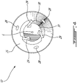
Fig. 4 is a front view of the swirler core ofFIG. 3 . -
FIG. 1 shows an axial cross-section through an example gas turbine engine. WhileFIG. 1 illustratively shows a turbo-fan type gas turbine engine, it is understood that the present disclosure is applicable to other types of gas turbine aircraft engines as well. In the illustrated case, air intake into the engine passes over fan blades 1 in a fan case 2 and is then split into an outer annular flow through thebypass duct 3 and an inner flow through the low-pressure axial compressor 4 and high-pressure centrifugal compressor 5. Compressed air exits the compressor 5 through a diffuser 6 and is contained within a plenum 7 that surrounds the combustor 8. Fuel is supplied to the combustor 8 throughfuel tubes 9 and fuel is mixed with air from the plenum 7 when sprayed through nozzles into the combustor 8 as a fuel air mixture that is ignited. A portion of the compressed air within the plenum 7 is admitted into the combustor 8 through orifices in the side walls to create a cooling air curtain along the combustor walls or is used for cooling to eventually mix with the hot gases from the combustor 8 and pass over thenozzle guide vane 10 andturbines 11 before exiting the tail of the engine as exhaust. - As will be discussed in further detail below, the present disclosure is directed to fuel nozzles at the terminus of the
fuel tubes 9 which direct an atomized fuel-air mixture into the combustor 8. A fuel nozzle includes a concentric array of compressed air orifices to create a swirling air flow surrounding a central fuel injecting swirler. The resultant shear forces between air and fuel cause the fuel and air mix together and form an atomized fuel-air mixture for combustion. -
FIG. 2 shows an isometric cross-section view of an exemplary embodiment of afuel swirler 12 for a fuel nozzle. For simplicity, the outer components of the fuel nozzle that serve to direct compressed air are not shown. The fuel swirler 12 comprises aswirler core 13 having aninternal bore 14 extending longitudinally through theswirler core 13 along a longitudinal axis L through which fuel is transported as will be discussed in further detail below. According to the illustrated embodiment theinternal bore 14 is a central bore coaxial to the centerline of the swirler core. Theswirler core 13 is axially mounted inside aninterior chamber 15 of aswirler housing 16. Theswirler core 13 is axially insertable through anopening 17 in theswirler housing 16 at an upstream end U.E. of thefuel swirler 12 relative to a fuel flow direction F. As will be discussed in further detail below, fuel from theswirler core 13 exits thefuel swirler 12 via afuel outlet 18 at a downstream end D.E. of thefuel swirler 12. Theinterior chamber 15 includes asocket portion 19 downstream of theopening 17 and atransition portion 20 downstream of thesocket portion 19 and upstream of thefuel outlet 18. In various cases, the outer surface of theswirler housing 16 is shaped to optimize the aerodynamic performance of thefuel swirler 12 in relation to the streams of compressed air while maintaining the required strength and structural integrity of thefuel swirler 12. - The
swirler core 13 has a generally cylindrical exterior surface and includes ashank portion 21 concentrically positionable within thesocket portion 19 of theinterior chamber 15. An annular air channel orair gap 22 is formed radially between the exterior surface of theswirler core 13 and the bounding wall of theinterior chamber 15 of theswirler housing 16. Thisair gap 22 may extend, for instance along the axial length of theshank portion 21. Such anair gap 22 may provide an added layer of thermal insulation for the flow of fuel F travelling internally through theswirler core 13. In various cases, theswirler core 13 and/orswirler housing 16 may be dimensioned to increase or decrease the thickness of theair gap 22 to vary the provided level of thermal insulation. Fuel may be provided to theinternal bore 14 via afuel inlet 23, receiving fuel from thefuel tubes 9. According to the illustrated embodiment, thefuel inlet 23 is provided at the upstream end of theswirler core 13 and is axially aligned with theinternal bore 14. - Referring additionally to
FIGS. 3 and4 , theswirler core 13 further includes adownstream end portion 24 abuttable against the wall of thetransition portion 20 of theinterior chamber 15. As will be discussed in further detail below, the level of engagement between theend portion 24 and thetransition portion 20 may be chosen to meter or control the rate of fuel flow F exiting thefuel swirler 12 throughfuel outlet 18. Illustratively, theend portion 24 includes afrustoconical portion 25 and a protruding tapered abuttingportion 26 extending axially from thefrustoconical portion 25. In the shown embodiment, as can be seen inFIG. 2 , thefrustoconical portion 25 begins to taper axially upstream of thetransition portion 20 of theinterior chamber 15, creating anannular fuel gallery 27. Fuel may exit theinternal bore 14 of theswirler core 13 via one or more exit holes 28 disposed in theend portion 24, illustratively on thefrustoconical portion 25. The exit holes 28 are fluidly connected to thefuel gallery 27 to direct the fuel passing through theinternal bore 14 into thefuel gallery 27. While the shownswirler core 13 includes threeexit holes 28, it is understood that more or less exit holes 28 may be provided depending on the desired fuel flow. In addition while the shown exit holes 28 are circular, other shaped holes may be contemplated as well. In the shown case, theexit holes 28 are formed into theswirler core 13 at an acute angle with the longitudinal axis L, for instance by being drilled or otherwise machined. The angle at which the exit hole(s) 28 are formed may vary, for instance, to increase or decrease the swirling effect provided to the exiting fuel. - The
fuel swirler 12 further includes one or more spaced apart recessed fuel channels orslots 29 disposed in theend portion 24, illustratively on theabutting portion 26. In the shown embodiment, theabutting portion 26 includes afrustoconical sidewall 30 and aflat end face 31. Illustratively, the fuel channel(s) 29 begin at an annularrecessed portion 32 of theend portion 24, extend the axial length of thesidewall 30 and open at theend face 31. Thefuel channels 29 cooperate with the wall of theswirler housing 16 circumscribing thetransition portion 20 to define metering passages for metering the flow of fuel from thefuel gallery 27. Other configurations for theend portion 24 may be contemplated as well. - Fuel exiting the
internal bore 14 of theswirler core 13 through the exit hole(s) 28 is directed through the fuel channel(s) 29 towards thefuel outlet 18. The fuel travels through the one ormore fuel channels 29 in a smaller, i.e. less voluminous, stream than in theinternal bore 14, and as such is enabled to atomize into small droplets as it exits through thefuel outlet 18. The fuel exiting through thefuel outlet 18 in this atomized state, i.e. in small droplets, is combined with compressed air (not shown) and directed towards the combustor 8. In the shown case, threefuel channels 29 with square cross-sectional shapes are helically disposed about the abuttingportion 26, although in other cases the number, cross-sectional shape and/or positioning about the abuttingportion 26 may vary. For instance, while the illustratedfuel channels 29 are helically disposed about the abuttingportion 26, in other cases the fuel channel(s) 29 may be axially disposed about the abuttingportion 26, i.e. parallel to the longitudinal axis L. In addition, while the illustratedfuel channels 29 include square cross-sectional shapes, in other cases the cross-sectional shape of the fuel channel(s) 29 may be semi-circular or triangular. Other cross-sectional shapes may be contemplated as well. - The flow of fuel is best shown in
FIG. 2 together with additional reference toFIGS. 3 and4 . Fuel under pressure enters via thefuel inlet 23 into theinternal bore 14 of theswirler core 13. The fuel exits theinternal bore 14 via the exit hole(s) 28 and is directed via thefuel gallery 27 through the fuel channel(s) 29 disposed in theend portion 24 towards thefuel outlet 18 and out of thefuel swirler 12. An axial fuel path is thus defined between thefuel inlet 23 and thefuel outlet 18. - In various embodiments, the number of exit holes 28 corresponds to the number of
fuel channels 29. In some cases, the number offuel channels 29 is a multiple of the number of exit holes 28. Illustratively, theend portion 24 includes threeexit holes 28 and threefuel channels 29, although other numbers of exit holes 28 and/orfuel channels 29 may be considered. In an alternate embodiment, for instance, theend portion 24 may include twoexit holes 28 and fourfuel channels 29. Other numbers of exit holes 28 andfuel channels 29 may be contemplated as well. The exit of theholes 28 can be placed such that the fuel directly feeds into thefuel channels 29, or feeds in between thechannels 29 . In the exemplary embodiment shown infigure 4 , the exit of theholes 28 are circumferentially in-between thechannels 29. That is the "clocking" of the exit holes 28 is different from that of thechannels 29. - In the shown case, the
internal bore 14 is a central cylindrical bore along the longitudinal axis L through which fuel is transported, although other bore shapes and configurations may be contemplated as well. For instance, in some cases theinternal bore 14 may be slightly offset from and parallel to the longitudinal axis L. In other cases, theswirler core 13 may alternatively include two or moreinternal bores 14 to transport the fuel. In various cases, the dimensions of theinternal bore 14 and the exit hole(s) 28 are selected so that the flow of fuel through the swirler is metered by the fuel channel(s) 29. Stated differently, theswirler core 13 may be dimensioned so that the rate of fuel flow F through theinternal bore 14 and the hole(s) 28 is greater than the allowable rate of fuel flow through the combined one ormore fuel channel 29. For instance, theswirler core 13 may be dimensioned so that the cross-sectional area of theinternal bore 14 is three times greater than the combined cross-sectional areas of the fuel channel(s) 29. In the illustrated case where theend portion 24 includes threefuel channels 29, eachfuel channel 29 may allow a rate of fuel flow that is nine times less than the rate of fuel flow F through theinternal bore 14. Other relative fuel flow rates may be contemplated as well. In various cases, when the cross-sectional area of theinternal bore 14 is greater than the combined cross-sectional areas of the fuel channel(s) 29, thefuel channels 29 will be metering the flow of fuel F. In various cases, fuel exiting theinternal bore 14 via exit holes 28 may accumulate in thefuel gallery 27 before passing through the fuel channel(s) 29. - As discussed above, the
fuel swirler 12 may be assembled by inserting theswirler core 13 through the opening of the 17 of theswirler housing 16. In various embodiments, the rate of fuel flow F may be controlled based on the depth of insertion of theswirler core 13 into theinterior chamber 15 of theswirler housing 16. By selectively pressing the abuttingportion 26 against thetransition portion 20 of theinterior chamber 15, the fuel channel(s) 29 become increasingly covered or closed off due to the tapered profiles of thetransition portion 20 and thefrustoconical sidewall 30 of the abuttingportion 26. As such, the rate of fuel flow F may be controlled. In various cases, thetransition portion 20 and thefrustoconical sidewall 30 may taper at different rates to alter the effect that the continued insertion of theswirler core 13 into theinterior chamber 15 has on the rate of fuel flow F. - For instance, in an exemplary assembly process, the
swirler core 13 is inserted into the interior chamber with the abuttingportion 26 engaging thetransition portion 20. Then, fuel is directed through theinternal bore 14 via thefuel inlet 23, with the rate of fuel flow F exiting thefuel swirler 12 via thefuel outlet 18 is monitored, for instance via a flow meter (not shown). Then, the depth of theswirler core 13 within theinterior chamber 15 is adjusted in either direction to modulate the exposed portion of the fuel channel(s) 29, i.e. the surface area through which fuel may exit from the fuel channel(s) 29, thus increasing or decreasing the rate of fuel flow F until a desired flow rate has been achieved. At such a point, the flow of fuel F may be stopped. As such, a desired level of engagement between thetransition portion 20 and the abuttingportion 26 may be selected to modulate the desired fuel flow rate. Other methods of achieving a desired fuel flow rate may be contemplated as well. - By assembling the
fuel swirler 12 via the above-described method, the fuel channel(s) 29 may be manufactured into theend portion 24 with larger dimensions than required since their cross-sectional area is reduced as theswirler core 13 is inserted into theinterior chamber 15. Such allowance may facilitate the overall manufacturing process of the fuel swirler, for instance by appeasing various manufacturing tolerances. - Once a desired flow rate has been achieved, the
swirler core 13 is fixed to theswirler housing 16. In some cases, theswirler core 13 andswirler housing 16 may be fixed together through a brazing process. For instance, a thin layer of gold paste (not shown) is applied to ashoulder 33 of theswirler core 13 before its insertion into theswirler housing 16. Once a desired flow rate has been achieved, thefuel swirler 12 may be heated, for instance in a furnace, to solidify the gold paste into an adhesive. Such an adhesive may maintain theswirler core 13 at the previously-selected depth for a desired flow rate and affix theswirler core 13 andswirler housing 16 together, readying thefuel swirler 12 for use. Other methods of fixing theswirler core 13 to theswirler housing 16 may be contemplated as well, for instance through various welding processes. - In the shown case, the
interior chamber 15 of theswirler housing 16 includes a radiallythicker portion 34, illustratively at the downstream end of thesocket portion 19. Thisthicker portion 34 decreases the diameter of theinterior chamber 15, adding a level of resistance when inserting theswirler core 13 into theinterior chamber 15. This added resistance may facilitate the above-described method of metering the flow of fuel, for instance by offering more control of the depth of theswirler core 13 to the user. The thickness of thethicker portion 34 may be selected based on the desired level of resistance against the insertedswirler core 13, among other considerations. In addition, in various cases thethicker portion 34 may provide a barrier between theair gap 22 and theannular fuel gallery 27 when theswirler core 13 is inserted in theinterior chamber 15, preventing the fuel in thefuel gallery 27 and the air in theair gap 22 from undesirably mixing. - In various embodiments, at least various portions of the
swirler core 13 and/orswirler housing 16 are axisymmetric about the longitudinal axis L. In the shown case, for instance, theshank portion 21 of theswirler core 13 is axisymmetric about the longitudinal axis L. As such, when theswirler core 13 is inserted into theswirler housing 16 and abutted against thetransition portion 20, theshank portion 21 will resist against bending, plastically deforming or otherwise undesirably distorting. Anaxisymmetric swirler core 13 under axial force will have balanced compressive axial stresses radially across the uniform cross-sectional area of theswirler core 13. There is no force imbalance to create non-elastic bending, buckling or lateral distortion since the axisymmetric cross-section provides an axisymmetric distribution of stress. - In the shown case, both the
swirler core 13 and theswirler housing 16 are axisymmetric about the longitudinal axis L. As such, theair gap 22 may be consistently maintained about the circumference of theswirler core 13. This provides a consistent layer of thermal insulation to the flow of fuel F throughout theinternal bore 14, ensuring the fuel temperature is maintained at a low enough temperature based on the given engine's requirements. In addition, by directing the fuel flow F through theinternal bore 14 of theswirler core 13 rather than between theswirler core 13 and theswirler housing 16, as is typically the case, the temperature of the fuel is further reduced, which in some cases may extend the life expectancy of the fuel nozzle. For instance, in various cases the fuel nozzles in a given gas turbine engine are surrounded by various sources of heat, so the placement of the axial fuel path through theinternal bore 14 of theswirler core 13 provides the greatest possible separation between the fuel and such sources of heat. - In such axisymmetric cases, any number of exit holes 28 in excess of one and
fuel channels 29 in excess of one can be arranged in a circumferentially spaced apart array that results in an axisymmetric cross-section. For instance,FIG. 4 shows threeexit holes 28 and threefuel channels 29, but two or more exit holes and/or two ormore fuel channels 29 can be axisymmetrically distributed with reference to the longitudinal axis L in other manners as well. - Various manufacturing processes may be utilized to produce the
swirler core 13 andswirler housing 16. Traditional manufacturing and removal techniques using machines such as lathes and mills may be implemented. Other manufacturing techniques such as additive manufacturing and metal injection moulding may be contemplated as well. As discussed above, various brazing or welding procedures may be utilized to fix theswirler core 13 to theswirler housing 16. - The embodiments described in this document provide non-limiting examples of possible implementations of the present technology. Upon review of the present disclosure, a person of ordinary skill in the art will recognize that changes may be made to the embodiments described herein without departing from the scope of the present technology. Yet further modifications could be implemented by a person of ordinary skill in the art in view of the present disclosure, which modifications would be within the scope of the present technology.
Claims (15)
- A fuel swirler (12) for a gas turbine engine fuel nozzle, comprising:a swirler housing (16) defining an interior chamber (15) having a fuel outlet (18) at a downstream end (D.E) relative to a fuel flow direction (F) through the fuel swirler (12);a swirler core (13) mounted inside the interior chamber (15), the swirler core (13) having a downstream end portion (24) with one or more fuel channels (29) disposed thereon, the one or more fuel channels (29) in fluid communication with the fuel outlet (18), an internal bore (14) extending longitudinally through the swirler core (13), the internal bore (14) having an inlet (23) connectable to a source of fuel, and one or more exit holes (28) fluidly connecting the internal bore (14) to the one or more fuel channels (29); andan annular air gap (22) radially between the swirler housing (16) and the swirler core (13) for thermally shielding the internal bore (14).
- The fuel swirler (12) as defined in claim 1, wherein the downstream end portion (24) of the swirler core (13) includes a frustoconical portion (25) through which the one or more exit holes (28) pass and a tapered abutting portion (26) which the one or more fuel channels (29) are disposed within.
- The fuel swirler (12) as defined in claim 1 or 2, wherein the one or more fuel channels (29) include a number of fuel channels that is a multiple of a number of the one or more exit holes (28).
- The fuel swirler (12) as defined in any preceding claim, wherein the swirler core (13) has a central axis (L), and wherein the swirler core (13) is axisymmetric about the central axis (L).
- The fuel swirler (12) as defined in any preceding claim, wherein a cross-sectional area of the internal bore (14) is greater than a combined cross-sectional area of the one or more fuel channels (29).
- The fuel swirler (12) as defined in any preceding claim, wherein the downstream end portion (24) of the swirler core (13) is engageable with a tapered transition portion (20) of the interior chamber (15) to regulate the rate of fuel flowable through the one or more fuel channels (29).
- The fuel swirler (12) as defined in any preceding claim, wherein the internal bore (14) is a central cylindrical bore axially disposed along a or the central axis (L) of the swirler core (13).
- The fuel swirler (12) as defined in any preceding claim, wherein the one or more fuel channels (29) are disposed helically about the downstream end portion (24) of the swirler core (13).
- The fuel swirler (12) as defined in any preceding claim, wherein:the interior chamber (15) defines a or the tapered transition portion (20) axially disposed upstream of the fuel outlet (18) and a socket portion (19) upstream of the transition portion (20); andthe swirler core (13) has a cylindrical shank portion (21), the downstream end portion (24) axially disposed downstream of the shank portion (21), the shank portion (21) concentrically positionable within the socket portion (19) and defining the annular air gap (22) therebetween, the downstream end portion (24) engageable with the transition portion (20) of the interior chamber (15).
- The fuel swirler (12) as defined in any preceding claim, wherein the one or more fuel channels (29) have a square-shape cross-section.
- A method of assembling a fuel swirler (12) for a gas turbine engine, the fuel swirler (12) including a swirler housing (16) and a swirler core (13), the method comprising:inserting an end of the swirler core (13) into an interior chamber (15) of the swirler housing (16), an annular air gap (22) forming between the swirler core (13) and the swirler housing (16);abutting the inserted end of the swirler core (13) against a transition portion (20) of the interior chamber (15) adjacent a fuel outlet (18) in the swirler housing (16), the fuel outlet (18) in fluid communication with an axial fuel path extending through an internal bore (14) of the swirler core (13) and through one or more exit holes (28) fluidly connecting the internal bore (14) to one or more fuel channels (29) disposed in the inserted end of the swirler core (13);modulating the depth of the inserted end of the swirler core (13) based on a desired engagement level between the transition portion (20) and the one or more fuel channels (29); andfixing the swirler core (13) to the swirler housing (16).
- The method as defined in claim 11, wherein modulating the depth of the inserted end of the swirler core (13) further includes directing fuel through the axial fuel path, monitoring the rate of fuel flow (F) exiting through the fuel outlet (18), and selecting the desired level of engagement based on a desired rate of exiting fuel flow (F).
- The method as defined in claim 11 or 12, wherein fixing the swirler core (13) to the swirler housing (16) includes applying a heat-based adhesive to a shoulder portion (33) of the swirler core (13) prior to inserting the end of the swirler core (13) into the interior chamber (15), and applying heat to the fuel swirler (12) to activate the adhesive subsequent to modulating the depth of the inserted end of the swirler core (13).
- The method as defined in claim 13, wherein applying the heat-based adhesive to the shoulder portion (33) of the swirler core (13) includes applying a gold-based brazing compound.
- The method as defined in claim 13 or 14, wherein applying heat to the fuel swirler (12) includes placing the fuel swirler (12) in a furnace to activate the adhesive.
Priority Applications (1)
| Application Number | Priority Date | Filing Date | Title |
|---|---|---|---|
| EP23199900.4A EP4286057A3 (en) | 2020-11-24 | 2021-11-24 | Fuel swirler for pressure fuel nozzles |
Applications Claiming Priority (1)
| Application Number | Priority Date | Filing Date | Title |
|---|---|---|---|
| US17/102,638 US20220163205A1 (en) | 2020-11-24 | 2020-11-24 | Fuel swirler for pressure fuel nozzles |
Related Child Applications (1)
| Application Number | Title | Priority Date | Filing Date |
|---|---|---|---|
| EP23199900.4A Division EP4286057A3 (en) | 2020-11-24 | 2021-11-24 | Fuel swirler for pressure fuel nozzles |
Publications (2)
| Publication Number | Publication Date |
|---|---|
| EP4001764A1 true EP4001764A1 (en) | 2022-05-25 |
| EP4001764B1 EP4001764B1 (en) | 2023-09-27 |
Family
ID=78789745
Family Applications (2)
| Application Number | Title | Priority Date | Filing Date |
|---|---|---|---|
| EP23199900.4A Pending EP4286057A3 (en) | 2020-11-24 | 2021-11-24 | Fuel swirler for pressure fuel nozzles |
| EP21210269.3A Active EP4001764B1 (en) | 2020-11-24 | 2021-11-24 | Fuel swirler for pressure fuel nozzles |
Family Applications Before (1)
| Application Number | Title | Priority Date | Filing Date |
|---|---|---|---|
| EP23199900.4A Pending EP4286057A3 (en) | 2020-11-24 | 2021-11-24 | Fuel swirler for pressure fuel nozzles |
Country Status (4)
| Country | Link |
|---|---|
| US (1) | US20220163205A1 (en) |
| EP (2) | EP4286057A3 (en) |
| CA (1) | CA3138797A1 (en) |
| PL (1) | PL4001764T3 (en) |
Families Citing this family (1)
| Publication number | Priority date | Publication date | Assignee | Title |
|---|---|---|---|---|
| KR102460672B1 (en) * | 2021-01-06 | 2022-10-27 | 두산에너빌리티 주식회사 | Fuel nozzle, fuel nozzle module and combustor having the same |
Citations (5)
| Publication number | Priority date | Publication date | Assignee | Title |
|---|---|---|---|---|
| US2854285A (en) * | 1954-06-04 | 1958-09-30 | Chrysler Corp | Air atomizing nozzle |
| US4134606A (en) * | 1977-11-10 | 1979-01-16 | Parker-Hannifin Corporation | Weld joint |
| US6547163B1 (en) * | 1999-10-01 | 2003-04-15 | Parker-Hannifin Corporation | Hybrid atomizing fuel nozzle |
| DE10257809A1 (en) * | 2002-12-10 | 2004-06-24 | Swoboda, Walter, 71543 Stocksberg | Binary jet nozzle for atomization of fluids, e.g. fuels has component arrangement to reduce required atomization air volume to below 80% |
| US20120292408A1 (en) * | 2011-05-18 | 2012-11-22 | Delavan Inc. | Multipoint injectors with standard envelope characteristics |
Family Cites Families (22)
| Publication number | Priority date | Publication date | Assignee | Title |
|---|---|---|---|---|
| US4139157A (en) * | 1976-09-02 | 1979-02-13 | Parker-Hannifin Corporation | Dual air-blast fuel nozzle |
| US4798330A (en) * | 1986-02-14 | 1989-01-17 | Fuel Systems Textron Inc. | Reduced coking of fuel nozzles |
| US4938417A (en) * | 1989-04-12 | 1990-07-03 | Fuel Systems Textron Inc. | Airblast fuel injector with tubular metering valve |
| US5697553A (en) * | 1995-03-03 | 1997-12-16 | Parker-Hannifin Corporation | Streaked spray nozzle for enhanced air/fuel mixing |
| DE19535195B4 (en) * | 1995-09-22 | 2005-09-29 | Pierburg Gmbh | Pressure atomizer nozzle for burner systems |
| US6357222B1 (en) * | 2000-04-07 | 2002-03-19 | General Electric Company | Method and apparatus for reducing thermal stresses within turbine engines |
| US7513116B2 (en) * | 2004-11-09 | 2009-04-07 | Woodward Fst, Inc. | Gas turbine engine fuel injector having a fuel swirler |
| RU2329873C2 (en) * | 2006-08-24 | 2008-07-27 | Андрей Леонидович Душкин | Liquid sprayer |
| US8752386B2 (en) * | 2010-05-25 | 2014-06-17 | Siemens Energy, Inc. | Air/fuel supply system for use in a gas turbine engine |
| US20120058437A1 (en) * | 2010-09-08 | 2012-03-08 | General Electric Company | Apparatus and method for mixing fuel in a gas turbine nozzle |
| US9010083B2 (en) * | 2011-02-03 | 2015-04-21 | General Electric Company | Apparatus for mixing fuel in a gas turbine |
| US20130081376A1 (en) * | 2011-10-03 | 2013-04-04 | Paul Reynolds | Pulse Detonation Engine with Variable Control Piezoelectric Fuel Injector |
| US9284888B2 (en) * | 2012-04-25 | 2016-03-15 | General Electric Company | System for supplying fuel to late-lean fuel injectors of a combustor |
| US9784452B2 (en) * | 2013-03-15 | 2017-10-10 | General Electric Company | System having a multi-tube fuel nozzle with an aft plate assembly |
| US9267436B2 (en) * | 2013-03-18 | 2016-02-23 | General Electric Company | Fuel distribution manifold for a combustor of a gas turbine |
| US9574776B2 (en) * | 2013-10-21 | 2017-02-21 | Delavan Inc. | Three-piece airblast fuel injector |
| US9915480B2 (en) * | 2014-07-03 | 2018-03-13 | United Technologies Corporation | Tube assembly |
| JP6621658B2 (en) * | 2015-12-22 | 2019-12-18 | 川崎重工業株式会社 | Fuel injection device |
| US10458331B2 (en) * | 2016-06-20 | 2019-10-29 | United Technologies Corporation | Fuel injector with heat pipe cooling |
| US10578306B2 (en) * | 2017-06-16 | 2020-03-03 | General Electric Company | Liquid fuel cartridge unit for gas turbine combustor and method of assembly |
| EP3425281B1 (en) * | 2017-07-04 | 2020-09-02 | General Electric Company | Pilot nozzle with inline premixing |
| US11149950B2 (en) * | 2018-06-11 | 2021-10-19 | Woodward, Inc. | Pre-swirl pressure atomizing tip |
-
2020
- 2020-11-24 US US17/102,638 patent/US20220163205A1/en active Pending
-
2021
- 2021-11-11 CA CA3138797A patent/CA3138797A1/en active Pending
- 2021-11-24 PL PL21210269.3T patent/PL4001764T3/en unknown
- 2021-11-24 EP EP23199900.4A patent/EP4286057A3/en active Pending
- 2021-11-24 EP EP21210269.3A patent/EP4001764B1/en active Active
Patent Citations (5)
| Publication number | Priority date | Publication date | Assignee | Title |
|---|---|---|---|---|
| US2854285A (en) * | 1954-06-04 | 1958-09-30 | Chrysler Corp | Air atomizing nozzle |
| US4134606A (en) * | 1977-11-10 | 1979-01-16 | Parker-Hannifin Corporation | Weld joint |
| US6547163B1 (en) * | 1999-10-01 | 2003-04-15 | Parker-Hannifin Corporation | Hybrid atomizing fuel nozzle |
| DE10257809A1 (en) * | 2002-12-10 | 2004-06-24 | Swoboda, Walter, 71543 Stocksberg | Binary jet nozzle for atomization of fluids, e.g. fuels has component arrangement to reduce required atomization air volume to below 80% |
| US20120292408A1 (en) * | 2011-05-18 | 2012-11-22 | Delavan Inc. | Multipoint injectors with standard envelope characteristics |
Also Published As
| Publication number | Publication date |
|---|---|
| CA3138797A1 (en) | 2022-05-24 |
| PL4001764T3 (en) | 2024-02-19 |
| EP4286057A3 (en) | 2024-02-21 |
| EP4286057A2 (en) | 2023-12-06 |
| EP4001764B1 (en) | 2023-09-27 |
| US20220163205A1 (en) | 2022-05-26 |
Similar Documents
| Publication | Publication Date | Title |
|---|---|---|
| US8387391B2 (en) | Aerodynamically enhanced fuel nozzle | |
| US8726668B2 (en) | Fuel atomization dual orifice fuel nozzle | |
| US7908863B2 (en) | Fuel nozzle for a gas turbine engine and method for fabricating the same | |
| EP2466206A2 (en) | Cooling flowpath dirt deflector in fuel nozzle | |
| EP3803208B1 (en) | Pre-swirl pressure atomizing tip | |
| CN108474557B (en) | Fuel injector with dual main fuel injection | |
| WO2017120037A1 (en) | Fuel injector with a center body assembly for liquid prefilm injection | |
| US11680527B2 (en) | Nozzles with internal manifolding | |
| CN108474556B (en) | Fuel injector with multi-tube gas distribution | |
| EP4001764B1 (en) | Fuel swirler for pressure fuel nozzles | |
| CN112334706B (en) | Fuel injector with centerbody assembly | |
| EP3736496A1 (en) | Fuel swirler for pressure fuel nozzles | |
| EP4086518A1 (en) | Fuel nozzle with integrated metering and flashback system | |
| WO2017120038A1 (en) | Two stream liquid fuel lean direct injection | |
| US20220268213A1 (en) | Dual pressure fuel nozzles |
Legal Events
| Date | Code | Title | Description |
|---|---|---|---|
| PUAI | Public reference made under article 153(3) epc to a published international application that has entered the european phase |
Free format text: ORIGINAL CODE: 0009012 |
|
| STAA | Information on the status of an ep patent application or granted ep patent |
Free format text: STATUS: THE APPLICATION HAS BEEN PUBLISHED |
|
| AK | Designated contracting states |
Kind code of ref document: A1 Designated state(s): AL AT BE BG CH CY CZ DE DK EE ES FI FR GB GR HR HU IE IS IT LI LT LU LV MC MK MT NL NO PL PT RO RS SE SI SK SM TR |
|
| STAA | Information on the status of an ep patent application or granted ep patent |
Free format text: STATUS: REQUEST FOR EXAMINATION WAS MADE |
|
| 17P | Request for examination filed |
Effective date: 20221125 |
|
| RBV | Designated contracting states (corrected) |
Designated state(s): AL AT BE BG CH CY CZ DE DK EE ES FI FR GB GR HR HU IE IS IT LI LT LU LV MC MK MT NL NO PL PT RO RS SE SI SK SM TR |
|
| GRAP | Despatch of communication of intention to grant a patent |
Free format text: ORIGINAL CODE: EPIDOSNIGR1 |
|
| STAA | Information on the status of an ep patent application or granted ep patent |
Free format text: STATUS: GRANT OF PATENT IS INTENDED |
|
| INTG | Intention to grant announced |
Effective date: 20230414 |
|
| GRAS | Grant fee paid |
Free format text: ORIGINAL CODE: EPIDOSNIGR3 |
|
| GRAA | (expected) grant |
Free format text: ORIGINAL CODE: 0009210 |
|
| STAA | Information on the status of an ep patent application or granted ep patent |
Free format text: STATUS: THE PATENT HAS BEEN GRANTED |
|
| AK | Designated contracting states |
Kind code of ref document: B1 Designated state(s): AL AT BE BG CH CY CZ DE DK EE ES FI FR GB GR HR HU IE IS IT LI LT LU LV MC MK MT NL NO PL PT RO RS SE SI SK SM TR |
|
| REG | Reference to a national code |
Ref country code: GB Ref legal event code: FG4D |
|
| REG | Reference to a national code |
Ref country code: CH Ref legal event code: EP |
|
| REG | Reference to a national code |
Ref country code: DE Ref legal event code: R096 Ref document number: 602021005444 Country of ref document: DE |
|
| REG | Reference to a national code |
Ref country code: IE Ref legal event code: FG4D |
|
| REG | Reference to a national code |
Ref country code: LT Ref legal event code: MG9D |
|
| PG25 | Lapsed in a contracting state [announced via postgrant information from national office to epo] |
Ref country code: GR Free format text: LAPSE BECAUSE OF FAILURE TO SUBMIT A TRANSLATION OF THE DESCRIPTION OR TO PAY THE FEE WITHIN THE PRESCRIBED TIME-LIMIT Effective date: 20231228 |
|
| PG25 | Lapsed in a contracting state [announced via postgrant information from national office to epo] |
Ref country code: SE Free format text: LAPSE BECAUSE OF FAILURE TO SUBMIT A TRANSLATION OF THE DESCRIPTION OR TO PAY THE FEE WITHIN THE PRESCRIBED TIME-LIMIT Effective date: 20230927 Ref country code: RS Free format text: LAPSE BECAUSE OF FAILURE TO SUBMIT A TRANSLATION OF THE DESCRIPTION OR TO PAY THE FEE WITHIN THE PRESCRIBED TIME-LIMIT Effective date: 20230927 Ref country code: NO Free format text: LAPSE BECAUSE OF FAILURE TO SUBMIT A TRANSLATION OF THE DESCRIPTION OR TO PAY THE FEE WITHIN THE PRESCRIBED TIME-LIMIT Effective date: 20231227 Ref country code: LV Free format text: LAPSE BECAUSE OF FAILURE TO SUBMIT A TRANSLATION OF THE DESCRIPTION OR TO PAY THE FEE WITHIN THE PRESCRIBED TIME-LIMIT Effective date: 20230927 Ref country code: LT Free format text: LAPSE BECAUSE OF FAILURE TO SUBMIT A TRANSLATION OF THE DESCRIPTION OR TO PAY THE FEE WITHIN THE PRESCRIBED TIME-LIMIT Effective date: 20230927 Ref country code: HR Free format text: LAPSE BECAUSE OF FAILURE TO SUBMIT A TRANSLATION OF THE DESCRIPTION OR TO PAY THE FEE WITHIN THE PRESCRIBED TIME-LIMIT Effective date: 20230927 Ref country code: GR Free format text: LAPSE BECAUSE OF FAILURE TO SUBMIT A TRANSLATION OF THE DESCRIPTION OR TO PAY THE FEE WITHIN THE PRESCRIBED TIME-LIMIT Effective date: 20231228 Ref country code: FI Free format text: LAPSE BECAUSE OF FAILURE TO SUBMIT A TRANSLATION OF THE DESCRIPTION OR TO PAY THE FEE WITHIN THE PRESCRIBED TIME-LIMIT Effective date: 20230927 |
|
| PGFP | Annual fee paid to national office [announced via postgrant information from national office to epo] |
Ref country code: FR Payment date: 20231019 Year of fee payment: 3 Ref country code: DE Payment date: 20231121 Year of fee payment: 3 Ref country code: CZ Payment date: 20231025 Year of fee payment: 3 |
|
| REG | Reference to a national code |
Ref country code: NL Ref legal event code: MP Effective date: 20230927 |
|
| REG | Reference to a national code |
Ref country code: AT Ref legal event code: MK05 Ref document number: 1615744 Country of ref document: AT Kind code of ref document: T Effective date: 20230927 |
|
| PG25 | Lapsed in a contracting state [announced via postgrant information from national office to epo] |
Ref country code: NL Free format text: LAPSE BECAUSE OF FAILURE TO SUBMIT A TRANSLATION OF THE DESCRIPTION OR TO PAY THE FEE WITHIN THE PRESCRIBED TIME-LIMIT Effective date: 20230927 |
|
| PG25 | Lapsed in a contracting state [announced via postgrant information from national office to epo] |
Ref country code: IS Free format text: LAPSE BECAUSE OF FAILURE TO SUBMIT A TRANSLATION OF THE DESCRIPTION OR TO PAY THE FEE WITHIN THE PRESCRIBED TIME-LIMIT Effective date: 20240127 |