EP4001740A1 - Light fixture with backup battery - Google Patents
Light fixture with backup battery Download PDFInfo
- Publication number
- EP4001740A1 EP4001740A1 EP21207068.4A EP21207068A EP4001740A1 EP 4001740 A1 EP4001740 A1 EP 4001740A1 EP 21207068 A EP21207068 A EP 21207068A EP 4001740 A1 EP4001740 A1 EP 4001740A1
- Authority
- EP
- European Patent Office
- Prior art keywords
- driver
- housing
- light fixture
- battery
- interior space
- Prior art date
- Legal status (The legal status is an assumption and is not a legal conclusion. Google has not performed a legal analysis and makes no representation as to the accuracy of the status listed.)
- Pending
Links
- 230000005611 electricity Effects 0.000 claims abstract description 6
- 230000004888 barrier function Effects 0.000 claims description 4
- 238000004891 communication Methods 0.000 claims description 2
- 231100001261 hazardous Toxicity 0.000 description 12
- 239000002184 metal Substances 0.000 description 5
- 239000007789 gas Substances 0.000 description 4
- 238000010276 construction Methods 0.000 description 3
- 239000000463 material Substances 0.000 description 3
- 229910000831 Steel Inorganic materials 0.000 description 2
- 239000000428 dust Substances 0.000 description 2
- 239000010959 steel Substances 0.000 description 2
- 239000000126 substance Substances 0.000 description 2
- CBENFWSGALASAD-UHFFFAOYSA-N Ozone Chemical compound [O-][O+]=O CBENFWSGALASAD-UHFFFAOYSA-N 0.000 description 1
- CYTYCFOTNPOANT-UHFFFAOYSA-N Perchloroethylene Chemical compound ClC(Cl)=C(Cl)Cl CYTYCFOTNPOANT-UHFFFAOYSA-N 0.000 description 1
- 238000009825 accumulation Methods 0.000 description 1
- 230000015572 biosynthetic process Effects 0.000 description 1
- 239000003245 coal Substances 0.000 description 1
- 230000006835 compression Effects 0.000 description 1
- 238000007906 compression Methods 0.000 description 1
- 239000004020 conductor Substances 0.000 description 1
- 238000001816 cooling Methods 0.000 description 1
- 238000005553 drilling Methods 0.000 description 1
- 230000000694 effects Effects 0.000 description 1
- 238000005516 engineering process Methods 0.000 description 1
- 230000007613 environmental effect Effects 0.000 description 1
- 239000002360 explosive Substances 0.000 description 1
- 238000005755 formation reaction Methods 0.000 description 1
- 238000004519 manufacturing process Methods 0.000 description 1
- 230000013011 mating Effects 0.000 description 1
- 238000005065 mining Methods 0.000 description 1
- 239000000203 mixture Substances 0.000 description 1
- 239000003921 oil Substances 0.000 description 1
- 229920000642 polymer Polymers 0.000 description 1
- 230000001681 protective effect Effects 0.000 description 1
- 230000005855 radiation Effects 0.000 description 1
- 150000003839 salts Chemical class 0.000 description 1
- 125000006850 spacer group Chemical group 0.000 description 1
- 238000005382 thermal cycling Methods 0.000 description 1
- 238000004065 wastewater treatment Methods 0.000 description 1
- XLYOFNOQVPJJNP-UHFFFAOYSA-N water Substances O XLYOFNOQVPJJNP-UHFFFAOYSA-N 0.000 description 1
Images





Classifications
-
- F—MECHANICAL ENGINEERING; LIGHTING; HEATING; WEAPONS; BLASTING
- F21—LIGHTING
- F21V—FUNCTIONAL FEATURES OR DETAILS OF LIGHTING DEVICES OR SYSTEMS THEREOF; STRUCTURAL COMBINATIONS OF LIGHTING DEVICES WITH OTHER ARTICLES, NOT OTHERWISE PROVIDED FOR
- F21V23/00—Arrangement of electric circuit elements in or on lighting devices
- F21V23/003—Arrangement of electric circuit elements in or on lighting devices the elements being electronics drivers or controllers for operating the light source, e.g. for a LED array
- F21V23/007—Arrangement of electric circuit elements in or on lighting devices the elements being electronics drivers or controllers for operating the light source, e.g. for a LED array enclosed in a casing
-
- F—MECHANICAL ENGINEERING; LIGHTING; HEATING; WEAPONS; BLASTING
- F21—LIGHTING
- F21S—NON-PORTABLE LIGHTING DEVICES; SYSTEMS THEREOF; VEHICLE LIGHTING DEVICES SPECIALLY ADAPTED FOR VEHICLE EXTERIORS
- F21S9/00—Lighting devices with a built-in power supply; Systems employing lighting devices with a built-in power supply
- F21S9/02—Lighting devices with a built-in power supply; Systems employing lighting devices with a built-in power supply the power supply being a battery or accumulator
-
- F—MECHANICAL ENGINEERING; LIGHTING; HEATING; WEAPONS; BLASTING
- F21—LIGHTING
- F21S—NON-PORTABLE LIGHTING DEVICES; SYSTEMS THEREOF; VEHICLE LIGHTING DEVICES SPECIALLY ADAPTED FOR VEHICLE EXTERIORS
- F21S9/00—Lighting devices with a built-in power supply; Systems employing lighting devices with a built-in power supply
- F21S9/02—Lighting devices with a built-in power supply; Systems employing lighting devices with a built-in power supply the power supply being a battery or accumulator
- F21S9/022—Emergency lighting devices
- F21S9/024—Emergency lighting devices using a supplementary light source for emergency lighting
-
- F—MECHANICAL ENGINEERING; LIGHTING; HEATING; WEAPONS; BLASTING
- F21—LIGHTING
- F21V—FUNCTIONAL FEATURES OR DETAILS OF LIGHTING DEVICES OR SYSTEMS THEREOF; STRUCTURAL COMBINATIONS OF LIGHTING DEVICES WITH OTHER ARTICLES, NOT OTHERWISE PROVIDED FOR
- F21V17/00—Fastening of component parts of lighting devices, e.g. shades, globes, refractors, reflectors, filters, screens, grids or protective cages
- F21V17/10—Fastening of component parts of lighting devices, e.g. shades, globes, refractors, reflectors, filters, screens, grids or protective cages characterised by specific fastening means or way of fastening
-
- F—MECHANICAL ENGINEERING; LIGHTING; HEATING; WEAPONS; BLASTING
- F21—LIGHTING
- F21V—FUNCTIONAL FEATURES OR DETAILS OF LIGHTING DEVICES OR SYSTEMS THEREOF; STRUCTURAL COMBINATIONS OF LIGHTING DEVICES WITH OTHER ARTICLES, NOT OTHERWISE PROVIDED FOR
- F21V23/00—Arrangement of electric circuit elements in or on lighting devices
- F21V23/02—Arrangement of electric circuit elements in or on lighting devices the elements being transformers, impedances or power supply units, e.g. a transformer with a rectifier
- F21V23/023—Power supplies in a casing
-
- F—MECHANICAL ENGINEERING; LIGHTING; HEATING; WEAPONS; BLASTING
- F21—LIGHTING
- F21V—FUNCTIONAL FEATURES OR DETAILS OF LIGHTING DEVICES OR SYSTEMS THEREOF; STRUCTURAL COMBINATIONS OF LIGHTING DEVICES WITH OTHER ARTICLES, NOT OTHERWISE PROVIDED FOR
- F21V29/00—Protecting lighting devices from thermal damage; Cooling or heating arrangements specially adapted for lighting devices or systems
- F21V29/15—Thermal insulation
-
- F—MECHANICAL ENGINEERING; LIGHTING; HEATING; WEAPONS; BLASTING
- F21—LIGHTING
- F21V—FUNCTIONAL FEATURES OR DETAILS OF LIGHTING DEVICES OR SYSTEMS THEREOF; STRUCTURAL COMBINATIONS OF LIGHTING DEVICES WITH OTHER ARTICLES, NOT OTHERWISE PROVIDED FOR
- F21V29/00—Protecting lighting devices from thermal damage; Cooling or heating arrangements specially adapted for lighting devices or systems
- F21V29/50—Cooling arrangements
- F21V29/70—Cooling arrangements characterised by passive heat-dissipating elements, e.g. heat-sinks
- F21V29/74—Cooling arrangements characterised by passive heat-dissipating elements, e.g. heat-sinks with fins or blades
- F21V29/77—Cooling arrangements characterised by passive heat-dissipating elements, e.g. heat-sinks with fins or blades with essentially identical diverging planar fins or blades, e.g. with fan-like or star-like cross-section
- F21V29/773—Cooling arrangements characterised by passive heat-dissipating elements, e.g. heat-sinks with fins or blades with essentially identical diverging planar fins or blades, e.g. with fan-like or star-like cross-section the planes containing the fins or blades having the direction of the light emitting axis
-
- F—MECHANICAL ENGINEERING; LIGHTING; HEATING; WEAPONS; BLASTING
- F21—LIGHTING
- F21V—FUNCTIONAL FEATURES OR DETAILS OF LIGHTING DEVICES OR SYSTEMS THEREOF; STRUCTURAL COMBINATIONS OF LIGHTING DEVICES WITH OTHER ARTICLES, NOT OTHERWISE PROVIDED FOR
- F21V29/00—Protecting lighting devices from thermal damage; Cooling or heating arrangements specially adapted for lighting devices or systems
- F21V29/50—Cooling arrangements
- F21V29/502—Cooling arrangements characterised by the adaptation for cooling of specific components
- F21V29/508—Cooling arrangements characterised by the adaptation for cooling of specific components of electrical circuits
-
- F—MECHANICAL ENGINEERING; LIGHTING; HEATING; WEAPONS; BLASTING
- F21—LIGHTING
- F21Y—INDEXING SCHEME ASSOCIATED WITH SUBCLASSES F21K, F21L, F21S and F21V, RELATING TO THE FORM OR THE KIND OF THE LIGHT SOURCES OR OF THE COLOUR OF THE LIGHT EMITTED
- F21Y2115/00—Light-generating elements of semiconductor light sources
- F21Y2115/10—Light-emitting diodes [LED]
Definitions
- the present disclosure generally relates to light fixtures and enclosures for light fixtures.
- Light fixtures are used in a variety of environments. Many of these light fixtures use advanced technology with a number of components. In lighting applications, such as hazardous environments (e.g., coal mines, petrochemical industries, etc.), reliability of the lighting system is vital. However, within these hazardous environments, power failure can be an issue. The characteristics (e.g., humidity, extreme temperatures, corrosive gas) of many environments, including but not limited to hazardous environments, can cause issues with the operability of one or more components of a light fixture. Additionally, outdoor electrical products can be in service for many years and are consistently exposed to extremely harsh environments, such as temperatures ranging from 0°C to 50°C, with constant exposure to ultraviolet radiation, rain, salt, fog, ozone, thermal cycling, corrosive chemicals, and the like.
- extremely harsh environments such as temperatures ranging from 0°C to 50°C
- a light fixture generally comprises a light housing defining an interior space.
- a light source is at least partially disposed in the interior space of the light housing.
- a driver housing is attached to the light housing and defines an interior space.
- a driver is disposed in the interior space of the driver housing for providing electricity to the light source.
- the driver is configured for connection to a main power source for energizing the light fixture.
- a battery is disposed in the interior space of the driver housing and is configured to provide backup power to the light fixture in the event of a loss of power from the main power source.
- an enclosure assembly generally comprises a driver housing defining an interior space.
- a driver is disposed in the interior space of the driver housing for providing electricity to an electrical component.
- a battery is disposed in the interior space of the driver housing and is configured to provide power to the electrical component.
- a separator plate is disposed in the interior space of the driver housing. The separator plate separates the interior space in the driver housing into an upper section and a lower section.
- a light fixture is generally indicated at 10.
- the light fixture comprises a housing 12 defining one or more interior spaces for enclosing the internal components of the fixture.
- the housing 12 comprises a plurality of housing components suitably connected together.
- the housing 12 could comprise a single housing component.
- the light fixture 10 can be used in a hazardous environment.
- example embodiments can be located in any type of hazardous environment, including but not limited to an airplane hangar, a drilling rig (as for oil, gas, or water), a production rig (as for oil or gas), a refinery, a chemical plant, a power plant, a mining operation, a wastewater treatment facility, and a steel mill.
- a hazardous environment can include a classified location.
- Hazardous locations may be defined by one or more of a number of authorities, including but not limited to the National Electric Code (e.g., Class 1, Division 2).
- a Class 1 hazardous area under the National Electric Code is an area in which flammable gases or vapors may be present in the air in sufficient quantities to be explosive.
- Standards created and maintained by NEMA may be found at www.nema.org .
- the present enclosure is a Class 1, Division 1 or Class 2, Division 1 hazardous location enclosure.
- an electrical enclosure is any type of cabinet or housing inside of which is disposed electrical, mechanical, electro-mechanical, and/or electronic equipment.
- Such equipment can include, but is not limited to, a controller (also called a control module), a hardware processor, a power supply (e.g., a battery, a driver, a ballast), a sensor module, a safety barrier, a sensor, sensor circuitry, a light source, electrical cables, and electrical conductors.
- Examples of an electrical enclosure can include, but are not limited to, a housing for a light fixture, a housing for a sensor device, an electrical connector, a junction box, a motor control center, a breaker box, an electrical housing, a conduit, a control panel, an indicating panel, and a control cabinet.
- the housing 12 comprises a first housing section 14 and a second housing section 16 attached to the first housing section.
- the first housing section 14 is disposed on top of the second housing section 16 and includes a bottom housing portion 18 and a top housing portion 20 attached to the bottom housing portion.
- the first housing section 14 alone may be considered a housing or part of a housing whereby the bottom housing portion 18 and the top housing portion 20 comprise first and second housing sections, respectively.
- the top housing portion 20 is hingedly attached to the bottom housing portion 18.
- a pin connection 22 may hingedly attach the top housing portion 20 to the bottom housing portion 18.
- the top housing portion 20 may be constructed from any suitable material.
- the top housing portion 20 is formed from metal such that the top housing portion may be characterized as a metal top hat.
- the first housing section 14 defines an interior space 23 configured for housing one or more components of the light fixture 10.
- the first housing section 14 defines an interior space for housing an LED driver assembly 26 for controlling the operation of the light fixture 10 and providing electricity to light sources 29 ( Fig. 3 ) of the light fixture housed in the second housing section 16.
- the driver assembly 26 is configured for connection to a main source of power for energizing the light fixture 10.
- the driver assembly 26 comprises a pair of LED drivers.
- the driver assembly 26 could comprise a single LED driver or more than two LED drivers without departing from the scope of the disclosure.
- the LED driver assembly 26 is housed within the bottom housing portion 18 of the first housing section 14.
- the bottom housing portion 18 comprises a metal housing such that the metal bottom housing portion defines the outermost housing structure around the driver components.
- the metal bottom housing portion 18 draws heat from the interior of the first housing section 14 to the exterior of the first housing section to transfer the heat to the periphery of the housing 12.
- the bottom housing portion 18 includes a bottom wall 30 and a circumferentially extending side wall 32 projecting upward from the bottom wall.
- a height H of the bottom housing portion 18 extends from the bottom to the top of the bottom housing portion. In one embodiment, the height H is between about 7 and about 8 inches. In one embodiment, the height H is about 7.55 inches.
- the bottom housing portion 18 also has an internal diameter D of between about 8 and about 10 inches. In one embodiment, the internal diameter D is about 8.97 inches.
- the height H and diameter D of the bottom housing portion 18 are greater than in a standard housing in similar light fixtures. This configures the bottom housing portion 18 to accommodate additional internal components of the light fixture 10. However, the bottom housing portion 18 is configured to mate with the top housing portion 20 and the second housing section 16 which have conventional constructions. Thus, the additional internal components of the light fixture 10 do not necessitate further reconfiguring of the top housing potion 20 or second housing section 16.
- the bottom housing portion 18 may be broadly considered a driver housing.
- Fins 34 may be disposed on or formed integrally with an exterior surface of the side wall 32 of the bottom housing portion 18.
- the fins 34 are integrated with the side wall 32 of the bottom housing portion 18.
- the fins 34 are circumferentially spaced equidistantly around the perimeter of the bottom housing portion 18 and extend vertically generally from a top of the bottom housing portion toward a bottom of the bottom housing portion.
- the fins 34 do not extend all the way to the bottom of the bottom housing portion 18 such that a lower section of the side wall 32 is free of fins providing an area for placing indicia such as name plates or other markings. Additionally, the fins 34 are relatively thin providing substantial gaps between the fins.
- each fin 34 extends from a raised annular portion 36 at the top of the bottom housing portion 18 and has a generally trapezoidal shape. As shown, a first side edge 38 of the fin 34 is concave a slopes downward, and a second side edge 40 of the fin is generally straight. The shape of the first side edge 38 further reduces the available surface area for dust accumulation.
- the fins 34 could have other constructions without departing from the scope of the disclosure. Additionally, the heat sink fins 34 can be of any number and/or have any of a number of configurations. The fins 34 increase the surface area of the bottom housing portion 18, thereby increasing its thermal transfer efficiency.
- a separator plate 42 is disposed within the interior space 23 of the bottom housing portion 18.
- the separator plate 42 comprises a generally disc shaped member 44 defining a pair of cut outs 46.
- the separator plate 42 is mounted on bosses 43 extending upward from the bottom wall 30 of the bottom housing portion 18 such that the separator plate is located above the bottom wall separating the interior space 23 into an upper section located above the separator plate and a lower section located below the spacer plate.
- the separator plate 42 defines fastener holes 45 for receiving fasteners 47 to mount the separator plate to the bosses 43. In the illustrated embodiment, there are three bosses 43.
- the cut outs 46 allow for wires to be routed between the upper and lower section in the bottom housing portion 18.
- the cut outs 46 are generally crescent shaped.
- the cut outs 46 could have other shapes without departing from the scope of the disclosure.
- the separator plate 42 may be formed from any suitable material including steel, polymer, etc. As will be explained in greater detail below, the separator plate 42 acts as a heat barrier between the components in the upper and lower sections of the bottom housing portion 18. In particular, the separator plate 42 blocks the flow of heat from the lower section to the upper section of the bottom housing portion 18 to regulate the temperature within the upper section.
- the LED driver assembly 26 is disposed below the separator plate 42 in the lower section of the bottom housing portion 18.
- the LED driver assembly 26 is mounted to the bottom wall 30 by fasteners 48.
- Thermal pads 50 may be disposed between each of the LED driver assembly 26 and the bottom wall 30 of the bottom housing portion 18. The thermal pads 50 help with thermal management when there is not proper contact between the LED driver assembly 26 and the bottom wall 30 of the bottom housing portion 18.
- a battery 52 and battery driver 54 are disposed above the separator plate 42 in the upper section of the bottom housing portion 18.
- the separator plate 42 acts as a heat barrier between the lower section and the upper section to help reduce the temperature around the battery 52 and battery driver 54 to maintain the battery within a workable operating range.
- Clamps 56 secure the battery 52 and battery driver 54 to the separator plate 42.
- two clamps 56 are shown whereby each clamp extends over both the battery 52 and the battery driver 54.
- a single clamp 56 or more than two clamps could be used without departing from the scope of the disclosure.
- Each clamp 56 comprises a cross bar 58 and arms 60 extending laterally from longitudinal ends of the cross bar.
- the arms 62 extend orthogonally from the cross bar 58. However, the arms 62 could extend from the cross bar 58 at other angles without departing from the scope of the disclosure.
- a flange 62 extends laterally from each arm 60. In the illustrated embodiment, the flanges 62 extend orthogonally from the arms 62 and away from the cross bar 58. However, the flanges 62 could extend in other directions and at other angles without departing from the scope of the disclosure.
- Each flange 62 defines a fastener hole 64 for receiving a fastener 66 (e.g., screws) to secure the clamp 56 to the separator plate 42.
- a rib 68 extends laterally from the cross bar 58 generally at a midpoint along the length of the cross bar.
- each clamp 56 has a height H2 such that a positive clamping force will be applied to the battery 52 and battery driver 54 in most cases regardless of the dimensions of the battery and battery driver. This allows the fastener screws 66 to be placed in tension preventing the screws from loosening during use of the light fixture 10.
- the height H2 of the clamps 56 is between about 1 and about 2 inches. In one embodiment, the height H2 of the clamps 56 is about 1.33 inches.
- Cushions 69 may also be disposed between each of the battery 52 and battery driver 54 and the cross bar 58 of the clamps 56.
- the height H2 provides a clearance for the cushions 69 to be disposed between the clamps 56 and the battery 52 and battery driver 54 to transfer the clamping force from the clamps to the battery 52 and battery driver 54.
- the cushions 69 account for any height differences between the battery 52 and battery driver 54 so that the clamps 56 can provide a sufficient compression force to both the battery and battery driver even if the components have different dimensions (e.g., heights).
- the battery 52 and battery driver 54 comprise an emergency battery unit. As such, the battery 52 can supply power to the light fixture 10 in the result of a loss of power from the main power source.
- the second housing section 16 is also configured to house one or more components of the light fixture 10.
- one or more light sources 29 can be disposed on or within, at least in part, the second housing section 16 of the housing 12.
- a protective cover or lens 31 may be provided on the second housing section 16 to cover the light sources 29.
- the housing 12 may have one or more communication links (not shown) disposed between the housing sections 14, 16 to operatively connect the components within separate housing sections.
- the housing sections 14, 16 can be designed to couple to each other in such a way that the entire housing 12 complies with applicable standards (e.g., hazardous location requirements).
- the second housing section 16 may be broadly considered a light housing.
- Fins 70 can be disposed on and/or integrated with the second housing section 16.
- the fins 70 are integrated with a portion of second housing section 16 of the housing 12.
- the fins 70 increase the surface area of the second housing section, thereby increasing its thermal transfer efficiency.
- the heat sink fins 70 can be of any number and/or have any of a number of configurations.
- the heat sink fins 70 are vertically-oriented protrusions that extend outward on the second housing section 16 of the housing 12 and are spaced substantially equidistantly around the outer perimeter of the second housing section.
- the heat sink fins 70 could have other configurations without departing from the scope of the disclosure.
- the overall construction of the light fixture 10 is configured to withstand the environmental conditions and physical demands of hazardous environments.
- the thermal endurance of the light fixture 10 ranges from about 0°C to about 50°C.
- the light fixture 10 is able to keep the critical components below a temperature of 100° C when the fixture is maintained within an environment of 50° C.
- the fixture 10 is able to keep the LED driver 26, battery driver 54, and battery 52 within a margin of 10° C with respect to the ambient environment. This allows the battery 52 to be operated within an internal fixture temperature of about 55° C while the light fixture 10 is disposed in ambient environment of about 45° C.
- the battery 52 also equips the light fixture 10 with a backup power source in the event of a loss of power to the light fixture from the main power source.
- the battery 52 is configured to power the light fixture 10 to provide greater than 1000 lumen for over 90 minutes.
- the battery 52 may also be configured to provide a greater or lesser amount of power to the light fixture 10 without departing from the scope of the disclosure.
Landscapes
- Engineering & Computer Science (AREA)
- General Engineering & Computer Science (AREA)
- Microelectronics & Electronic Packaging (AREA)
- Power Engineering (AREA)
- Arrangement Of Elements, Cooling, Sealing, Or The Like Of Lighting Devices (AREA)
- Non-Portable Lighting Devices Or Systems Thereof (AREA)
Abstract
A light fixture includes a light housing defining an interior space. A light source is at least partially disposed in the interior space of the light housing. A driver housing is attached to the light housing and defines an interior space. A driver is disposed in the interior space of the driver housing for providing electricity to the light source. The driver is configured for connection to a main power source for energizing the light fixture. A battery is disposed in the interior space of the driver housing and is configured to provide backup power to the light fixture in the event of a loss of power from the main power source.
Description
- This application claims priority to
U.S. Provisional Patent Application Serial No. 63/113,334, filed November 13, 2020 - The present disclosure generally relates to light fixtures and enclosures for light fixtures.
- Light fixtures are used in a variety of environments. Many of these light fixtures use advanced technology with a number of components. In lighting applications, such as hazardous environments (e.g., coal mines, petrochemical industries, etc.), reliability of the lighting system is vital. However, within these hazardous environments, power failure can be an issue. The characteristics (e.g., humidity, extreme temperatures, corrosive gas) of many environments, including but not limited to hazardous environments, can cause issues with the operability of one or more components of a light fixture. Additionally, outdoor electrical products can be in service for many years and are consistently exposed to extremely harsh environments, such as temperatures ranging from 0°C to 50°C, with constant exposure to ultraviolet radiation, rain, salt, fog, ozone, thermal cycling, corrosive chemicals, and the like.
- Reference is made to
U.S. Pat. Nos. 10,408,442 10,443,832 10,260,722 10,655,833 10,551,047 - In one aspect, a light fixture generally comprises a light housing defining an interior space. A light source is at least partially disposed in the interior space of the light housing. A driver housing is attached to the light housing and defines an interior space. A driver is disposed in the interior space of the driver housing for providing electricity to the light source. The driver is configured for connection to a main power source for energizing the light fixture. A battery is disposed in the interior space of the driver housing and is configured to provide backup power to the light fixture in the event of a loss of power from the main power source.
- In another aspect, an enclosure assembly generally comprises a driver housing defining an interior space. A driver is disposed in the interior space of the driver housing for providing electricity to an electrical component. A battery is disposed in the interior space of the driver housing and is configured to provide power to the electrical component. A separator plate is disposed in the interior space of the driver housing. The separator plate separates the interior space in the driver housing into an upper section and a lower section.
-
-
Fig. 1 is perspective of a light fixture; -
Fig. 2 is a top view of the light fixture; -
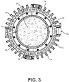
Fig. 3 is a bottom view of the light fixture; -
Fig. 4 is a top view of the light fixture with a top housing compartment removed to show internal detail of a driver compartment assembly; -
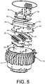
Fig. 5 is an exploded view of the driver compartment assembly; -
Fig. 6 is a side view of a driver housing of the driver compartment assembly; -
Fig. 7 is a top view of the driver housing; -
Fig. 8 is a perspective of a separator plate of the driver compartment assembly; -
Fig. 9 is a top view of the separator plate; -
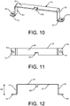
Fig. 10 is a perspective of a clamp of the driver compartment assembly; -
Fig. 11 is a top view of the clamp; and -
Fig. 12 is a side view of the clamp. - Referring to
Figs. 1-3 , a light fixture is generally indicated at 10. The light fixture comprises ahousing 12 defining one or more interior spaces for enclosing the internal components of the fixture. In the illustrated embodiment, thehousing 12 comprises a plurality of housing components suitably connected together. However, thehousing 12 could comprise a single housing component. In some embodiments, thelight fixture 10 can be used in a hazardous environment. In such a case, example embodiments can be located in any type of hazardous environment, including but not limited to an airplane hangar, a drilling rig (as for oil, gas, or water), a production rig (as for oil or gas), a refinery, a chemical plant, a power plant, a mining operation, a wastewater treatment facility, and a steel mill. A hazardous environment can include a classified location. - Hazardous locations may be defined by one or more of a number of authorities, including but not limited to the National Electric Code (e.g., Class 1, Division 2). For example, a Class 1 hazardous area under the National Electric Code is an area in which flammable gases or vapors may be present in the air in sufficient quantities to be explosive. Standards created and maintained by NEMA may be found at www.nema.org. In one or more example embodiments, the present enclosure is a Class 1, Division 1 or Class 2, Division 1 hazardous location enclosure.
- As defined herein, an electrical enclosure is any type of cabinet or housing inside of which is disposed electrical, mechanical, electro-mechanical, and/or electronic equipment. Such equipment can include, but is not limited to, a controller (also called a control module), a hardware processor, a power supply (e.g., a battery, a driver, a ballast), a sensor module, a safety barrier, a sensor, sensor circuitry, a light source, electrical cables, and electrical conductors. Examples of an electrical enclosure can include, but are not limited to, a housing for a light fixture, a housing for a sensor device, an electrical connector, a junction box, a motor control center, a breaker box, an electrical housing, a conduit, a control panel, an indicating panel, and a control cabinet.
- Referring to
Figs. 1-3 , thehousing 12 comprises afirst housing section 14 and asecond housing section 16 attached to the first housing section. Thefirst housing section 14 is disposed on top of thesecond housing section 16 and includes abottom housing portion 18 and atop housing portion 20 attached to the bottom housing portion. Thefirst housing section 14 alone may be considered a housing or part of a housing whereby thebottom housing portion 18 and thetop housing portion 20 comprise first and second housing sections, respectively. In one embodiment, thetop housing portion 20 is hingedly attached to thebottom housing portion 18. For example, apin connection 22 may hingedly attach thetop housing portion 20 to thebottom housing portion 18. When thetop housing portion 20 is pivoted to engage thebottom housing portion 18,mating locking formations 19 on the top andbottom housing portions top housing portion 20 may be constructed from any suitable material. In one embodiment, thetop housing portion 20 is formed from metal such that the top housing portion may be characterized as a metal top hat. Thefirst housing section 14 defines aninterior space 23 configured for housing one or more components of thelight fixture 10. In one embodiment, thefirst housing section 14 defines an interior space for housing anLED driver assembly 26 for controlling the operation of thelight fixture 10 and providing electricity to light sources 29 (Fig. 3 ) of the light fixture housed in thesecond housing section 16. Thedriver assembly 26 is configured for connection to a main source of power for energizing thelight fixture 10. In the illustrated embodiment, thedriver assembly 26 comprises a pair of LED drivers. However, thedriver assembly 26 could comprise a single LED driver or more than two LED drivers without departing from the scope of the disclosure. - Referring to
Figs. 4-7 , theLED driver assembly 26 is housed within thebottom housing portion 18 of thefirst housing section 14. In the illustrated embodiment, thebottom housing portion 18 comprises a metal housing such that the metal bottom housing portion defines the outermost housing structure around the driver components. The metalbottom housing portion 18 draws heat from the interior of thefirst housing section 14 to the exterior of the first housing section to transfer the heat to the periphery of thehousing 12. Thebottom housing portion 18 includes a bottom wall 30 and a circumferentially extendingside wall 32 projecting upward from the bottom wall. A height H of thebottom housing portion 18 extends from the bottom to the top of the bottom housing portion. In one embodiment, the height H is between about 7 and about 8 inches. In one embodiment, the height H is about 7.55 inches. Thebottom housing portion 18 also has an internal diameter D of between about 8 and about 10 inches. In one embodiment, the internal diameter D is about 8.97 inches. The height H and diameter D of thebottom housing portion 18 are greater than in a standard housing in similar light fixtures. This configures thebottom housing portion 18 to accommodate additional internal components of thelight fixture 10. However, thebottom housing portion 18 is configured to mate with thetop housing portion 20 and thesecond housing section 16 which have conventional constructions. Thus, the additional internal components of thelight fixture 10 do not necessitate further reconfiguring of thetop housing potion 20 orsecond housing section 16. Thebottom housing portion 18 may be broadly considered a driver housing. - Fins 34 (broadly, a first heat sink) may be disposed on or formed integrally with an exterior surface of the
side wall 32 of thebottom housing portion 18. In the illustrated embodiment, thefins 34 are integrated with theside wall 32 of thebottom housing portion 18. Thefins 34 are circumferentially spaced equidistantly around the perimeter of thebottom housing portion 18 and extend vertically generally from a top of the bottom housing portion toward a bottom of the bottom housing portion. Thefins 34 do not extend all the way to the bottom of thebottom housing portion 18 such that a lower section of theside wall 32 is free of fins providing an area for placing indicia such as name plates or other markings. Additionally, thefins 34 are relatively thin providing substantial gaps between the fins. This reduction in material reduces that area in which dust and debris can collect on thebottom housing portion 18. In the illustrated embodiment, eachfin 34 extends from a raisedannular portion 36 at the top of thebottom housing portion 18 and has a generally trapezoidal shape. As shown, afirst side edge 38 of thefin 34 is concave a slopes downward, and asecond side edge 40 of the fin is generally straight. The shape of thefirst side edge 38 further reduces the available surface area for dust accumulation. However, thefins 34 could have other constructions without departing from the scope of the disclosure. Additionally, theheat sink fins 34 can be of any number and/or have any of a number of configurations. Thefins 34 increase the surface area of thebottom housing portion 18, thereby increasing its thermal transfer efficiency. - Referring to
Figs. 5 ,8 , and9 , aseparator plate 42 is disposed within theinterior space 23 of thebottom housing portion 18. Theseparator plate 42 comprises a generally disc shapedmember 44 defining a pair ofcut outs 46. Theseparator plate 42 is mounted onbosses 43 extending upward from the bottom wall 30 of thebottom housing portion 18 such that the separator plate is located above the bottom wall separating theinterior space 23 into an upper section located above the separator plate and a lower section located below the spacer plate. Theseparator plate 42 defines fastener holes 45 for receivingfasteners 47 to mount the separator plate to thebosses 43. In the illustrated embodiment, there are threebosses 43. However, another number ofbosses 43 could be used without departing from the scope of the disclosure. Thecut outs 46 allow for wires to be routed between the upper and lower section in thebottom housing portion 18. In the illustrated embodiment, thecut outs 46 are generally crescent shaped. However, thecut outs 46 could have other shapes without departing from the scope of the disclosure. Theseparator plate 42 may be formed from any suitable material including steel, polymer, etc. As will be explained in greater detail below, theseparator plate 42 acts as a heat barrier between the components in the upper and lower sections of thebottom housing portion 18. In particular, theseparator plate 42 blocks the flow of heat from the lower section to the upper section of thebottom housing portion 18 to regulate the temperature within the upper section. - Referring to
Fig. 5 , theLED driver assembly 26 is disposed below theseparator plate 42 in the lower section of thebottom housing portion 18. TheLED driver assembly 26 is mounted to the bottom wall 30 byfasteners 48.Thermal pads 50 may be disposed between each of theLED driver assembly 26 and the bottom wall 30 of thebottom housing portion 18. Thethermal pads 50 help with thermal management when there is not proper contact between theLED driver assembly 26 and the bottom wall 30 of thebottom housing portion 18. - Referring to
Figs. 4 ,5 , and10-12 , abattery 52 andbattery driver 54 are disposed above theseparator plate 42 in the upper section of thebottom housing portion 18. Theseparator plate 42 acts as a heat barrier between the lower section and the upper section to help reduce the temperature around thebattery 52 andbattery driver 54 to maintain the battery within a workable operating range.Clamps 56 secure thebattery 52 andbattery driver 54 to theseparator plate 42. In the illustrated embodiment, twoclamps 56 are shown whereby each clamp extends over both thebattery 52 and thebattery driver 54. However, asingle clamp 56 or more than two clamps could be used without departing from the scope of the disclosure. Eachclamp 56 comprises across bar 58 andarms 60 extending laterally from longitudinal ends of the cross bar. In the illustrated embodiment, thearms 62 extend orthogonally from thecross bar 58. However, thearms 62 could extend from thecross bar 58 at other angles without departing from the scope of the disclosure. Aflange 62 extends laterally from eacharm 60. In the illustrated embodiment, theflanges 62 extend orthogonally from thearms 62 and away from thecross bar 58. However, theflanges 62 could extend in other directions and at other angles without departing from the scope of the disclosure. Eachflange 62 defines afastener hole 64 for receiving a fastener 66 (e.g., screws) to secure theclamp 56 to theseparator plate 42. Arib 68 extends laterally from thecross bar 58 generally at a midpoint along the length of the cross bar. Therib 68 extends between thebattery 52 andbattery driver 54 to space the battery from the battery driver. This provides a passage between thebattery 52 andbattery driver 54 for air flow which helps to improve the thermal efficiency of thelight fixture 10. In particular, it provides a cooling effect to thebattery 52 andbattery driver 54 to maintain the battery components at acceptable temperatures. Additionally, eachclamp 56 has a height H2 such that a positive clamping force will be applied to thebattery 52 andbattery driver 54 in most cases regardless of the dimensions of the battery and battery driver. This allows the fastener screws 66 to be placed in tension preventing the screws from loosening during use of thelight fixture 10. In one embodiment, the height H2 of theclamps 56 is between about 1 and about 2 inches. In one embodiment, the height H2 of theclamps 56 is about 1.33 inches.Cushions 69 may also be disposed between each of thebattery 52 andbattery driver 54 and thecross bar 58 of theclamps 56. The height H2 provides a clearance for thecushions 69 to be disposed between theclamps 56 and thebattery 52 andbattery driver 54 to transfer the clamping force from the clamps to thebattery 52 andbattery driver 54. Thecushions 69 account for any height differences between thebattery 52 andbattery driver 54 so that theclamps 56 can provide a sufficient compression force to both the battery and battery driver even if the components have different dimensions (e.g., heights). In one embodiment, thebattery 52 andbattery driver 54 comprise an emergency battery unit. As such, thebattery 52 can supply power to thelight fixture 10 in the result of a loss of power from the main power source. - The
second housing section 16 is also configured to house one or more components of thelight fixture 10. For example, one or more light sources 29 (Fig. 3 ) can be disposed on or within, at least in part, thesecond housing section 16 of thehousing 12. A protective cover orlens 31 may be provided on thesecond housing section 16 to cover thelight sources 29. Thehousing 12 may have one or more communication links (not shown) disposed between thehousing sections housing sections entire housing 12 complies with applicable standards (e.g., hazardous location requirements). Thesecond housing section 16 may be broadly considered a light housing. - Fins 70 (broadly, a second heat sink) can be disposed on and/or integrated with the
second housing section 16. In the illustrated embodiment, thefins 70 are integrated with a portion ofsecond housing section 16 of thehousing 12. Thefins 70 increase the surface area of the second housing section, thereby increasing its thermal transfer efficiency. Theheat sink fins 70 can be of any number and/or have any of a number of configurations. In the illustrated embodiment, theheat sink fins 70 are vertically-oriented protrusions that extend outward on thesecond housing section 16 of thehousing 12 and are spaced substantially equidistantly around the outer perimeter of the second housing section. Theheat sink fins 70 could have other configurations without departing from the scope of the disclosure. - The overall construction of the
light fixture 10 is configured to withstand the environmental conditions and physical demands of hazardous environments. In particular, the thermal endurance of thelight fixture 10 ranges from about 0°C to about 50°C. Thus, thelight fixture 10 is able to keep the critical components below a temperature of 100° C when the fixture is maintained within an environment of 50° C. In particular, thefixture 10 is able to keep theLED driver 26,battery driver 54, andbattery 52 within a margin of 10° C with respect to the ambient environment. This allows thebattery 52 to be operated within an internal fixture temperature of about 55° C while thelight fixture 10 is disposed in ambient environment of about 45° C. Thebattery 52 also equips thelight fixture 10 with a backup power source in the event of a loss of power to the light fixture from the main power source. In one embodiment, thebattery 52 is configured to power thelight fixture 10 to provide greater than 1000 lumen for over 90 minutes. Thebattery 52 may also be configured to provide a greater or lesser amount of power to thelight fixture 10 without departing from the scope of the disclosure. - When introducing elements of the present disclosure or the preferred embodiments(s) thereof, the articles "a", "an", "the" and "said" are intended to mean that there are one or more of the elements. The terms "comprising", "including" and "having" are intended to be inclusive and mean that there may be additional elements other than the listed elements.
- In view of the above, it will be seen that the several objects of the disclosure are achieved and other advantageous results attained.
- As various changes could be made in the compositions without departing from the scope of the disclosure, it is intended that all matter contained in the above description shall be interpreted as illustrative and not in a limiting sense.
Claims (15)
- A light fixture comprising:a light housing defining an interior space;a light source at least partially disposed in the interior space of the light housing;a driver housing attached to the light housing and defining an interior space;a driver disposed in the interior space of the driver housing for providing electricity to the light source, the driver being configured for connection to a main power source for energizing the light fixture; anda battery disposed in the interior space of the driver housing and configured to provide backup power to the light fixture in the event of a loss of power from the main power source.
- The light fixture of claim 1, further comprising a battery driver in the driver housing.
- The light fixture of claim 1, further comprising a separator plate disposed in the interior space of the driver housing, the separator plate separating the interior space in the driver housing into an upper section and a lower section.
- The light fixture of claim 3, wherein the driver is disposed in the lower section and the battery is disposed in the upper section.
- The light fixture of claim 3, further comprising a clamp securing the battery to the separator plate.
- The light fixture of claim 5, further comprising a battery driver in the upper section, the clamp securing the battery driver to the separator plate.
- The light fixture of claim 6, further comprising a cushion disposed between the clamp and at least one of the battery and battery driver.
- The light fixture of claim 6, wherein the battery driver is configured for controlling operation of one or more electrical components of the light fixture.
- The light fixture of claim 1, further comprising a heat sink in thermal communication with the light source.
- The light fixture of claim 9, wherein the heat sink comprises a plurality of fins formed on the driver housing.
- The light fixture of claim 1, wherein the fixture is a Class 1, Division 2 or a Class 2, Division 1 enclosure.
- An enclosure assembly comprising:a driver housing defining an interior space;a driver disposed in the interior space of the driver housing for providing electricity to an electrical component;a battery disposed in the interior space of the driver housing and configured to provide power to the electrical component; anda separator plate disposed in the interior space of the driver housing, the separator plate separating the interior space in the driver housing into an upper section and a lower section.
- The enclosure assembly of claim 12, wherein the driver is disposed in the lower section and the battery is disposed in the upper section.
- The enclosure assembly of claim 12, wherein the separator plate provides a thermal barrier between the upper and lower sections.
- The enclosure assembly of claim 12 wherein the assembly is a light fixture.
Applications Claiming Priority (1)
| Application Number | Priority Date | Filing Date | Title |
|---|---|---|---|
| US202063113334P | 2020-11-13 | 2020-11-13 |
Publications (1)
| Publication Number | Publication Date |
|---|---|
| EP4001740A1 true EP4001740A1 (en) | 2022-05-25 |
Family
ID=78820107
Family Applications (1)
| Application Number | Title | Priority Date | Filing Date |
|---|---|---|---|
| EP21207068.4A Pending EP4001740A1 (en) | 2020-11-13 | 2021-11-09 | Light fixture with backup battery |
Country Status (5)
| Country | Link |
|---|---|
| US (1) | US11835200B2 (en) |
| EP (1) | EP4001740A1 (en) |
| CN (1) | CN114484357A (en) |
| CA (1) | CA3138151A1 (en) |
| MX (1) | MX2021013691A (en) |
Families Citing this family (3)
| Publication number | Priority date | Publication date | Assignee | Title |
|---|---|---|---|---|
| USD1070142S1 (en) * | 2020-11-13 | 2025-04-08 | Eaton Intelligent Power Limited | Light fixture |
| US11821606B2 (en) * | 2021-09-30 | 2023-11-21 | Abl Ip Holding Llc | Light fixture with integrated backup power supply |
| US12442526B2 (en) * | 2023-12-12 | 2025-10-14 | Eaton Intelligent Power Limited | Light-emitting diode luminaire assembly |
Citations (7)
| Publication number | Priority date | Publication date | Assignee | Title |
|---|---|---|---|---|
| DE202016101832U1 (en) * | 2016-04-07 | 2017-07-11 | Tridonic Gmbh & Co Kg | Operating device with emergency power supply |
| CN206530980U (en) * | 2017-03-06 | 2017-09-29 | 南京布奇信息技术有限公司 | Building intelligent lighting device |
| CN107289406A (en) * | 2017-06-29 | 2017-10-24 | 惠州市超频三光电科技有限公司 | Solar energy lamp |
| CN207922021U (en) * | 2017-11-30 | 2018-09-28 | 深圳市必拓电子股份有限公司 | A kind of emergent bulkhead lamp |
| US20180320882A1 (en) * | 2017-05-05 | 2018-11-08 | Hubbell Incorporated | High lumen high-bay luminaire |
| US10260722B2 (en) | 2016-12-02 | 2019-04-16 | Eaton Intelligent Power Limited | Sensor modules for light fixtures |
| CN210179488U (en) * | 2019-08-20 | 2020-03-24 | 横店集团得邦照明股份有限公司 | Outdoor emergency induction industrial and mining lamp |
Family Cites Families (16)
| Publication number | Priority date | Publication date | Assignee | Title |
|---|---|---|---|---|
| AU2003245312A1 (en) * | 2002-05-24 | 2003-12-12 | B-K Lighting, Inc. | In-grade light fixture housing and hydrological barrier plate for use therein |
| US7059744B2 (en) * | 2003-11-07 | 2006-06-13 | Streamlight, Inc. | Flashlight having back light elements |
| CN201179488Y (en) | 2008-03-31 | 2009-01-14 | 浙江华立涂装设备有限公司 | Sample spray gun |
| GB201014056D0 (en) * | 2010-08-23 | 2010-10-06 | Litonics Ltd | Heatsink for lighting device |
| US20120155077A1 (en) * | 2010-12-17 | 2012-06-21 | Yuyang Dnu Co., Ltd. | Light emitting diode floodlight |
| US20120212945A1 (en) * | 2011-02-22 | 2012-08-23 | Frank Keery Frank | Light fixture |
| US9755448B2 (en) * | 2014-10-10 | 2017-09-05 | Revolution Lighting Technologies, Inc. | LED luminaire with integrated battery backup |
| US10274150B2 (en) * | 2014-10-10 | 2019-04-30 | Revolution Lighting Technologies, Inc. | LED luminaire with integrated battery backup |
| US10663130B2 (en) * | 2014-12-03 | 2020-05-26 | CP IP Holdings Limited | Lighting arrangement with battery backup |
| US9930758B2 (en) | 2015-09-15 | 2018-03-27 | Cooper Technologies Company | Light fixture as an access point in a communication network |
| US10900619B2 (en) | 2016-02-03 | 2021-01-26 | Fintronx, Llc | High-bay light-emitting diode (LED) light fixture |
| US10165647B2 (en) * | 2016-04-22 | 2018-12-25 | Hubbell Incorporated | Lighting fixture |
| US10054287B2 (en) * | 2016-05-25 | 2018-08-21 | Arctic Rays, Llc | High intensity marine LED strobe and torch light |
| US11578859B2 (en) * | 2016-07-15 | 2023-02-14 | TTP Holdings, LLC | Modular system |
| CN207849185U (en) * | 2017-10-10 | 2018-09-11 | 华荣科技股份有限公司 | A kind of industrial high protection emergency light |
| US10473318B2 (en) * | 2018-01-04 | 2019-11-12 | Appleton Grp Llc | LED fixture with air gap and heat dissipation |
-
2021
- 2021-11-08 CA CA3138151A patent/CA3138151A1/en active Pending
- 2021-11-08 US US17/454,049 patent/US11835200B2/en active Active
- 2021-11-09 MX MX2021013691A patent/MX2021013691A/en unknown
- 2021-11-09 EP EP21207068.4A patent/EP4001740A1/en active Pending
- 2021-11-15 CN CN202111346224.4A patent/CN114484357A/en active Pending
Patent Citations (11)
| Publication number | Priority date | Publication date | Assignee | Title |
|---|---|---|---|---|
| DE202016101832U1 (en) * | 2016-04-07 | 2017-07-11 | Tridonic Gmbh & Co Kg | Operating device with emergency power supply |
| US10260722B2 (en) | 2016-12-02 | 2019-04-16 | Eaton Intelligent Power Limited | Sensor modules for light fixtures |
| US10408442B2 (en) | 2016-12-02 | 2019-09-10 | Cooper Technologies Company | Hazardous location light fixture housings |
| US10443832B2 (en) | 2016-12-02 | 2019-10-15 | Cooper Technologies Company | Collars for light fixtures |
| US10551047B2 (en) | 2016-12-02 | 2020-02-04 | Eaton Intelligent Power Limited | Sensor modules for light fixtures |
| US10655833B2 (en) | 2016-12-02 | 2020-05-19 | Eaton Intelligent Power Limited | Antennae for hazardous location light fixtures |
| CN206530980U (en) * | 2017-03-06 | 2017-09-29 | 南京布奇信息技术有限公司 | Building intelligent lighting device |
| US20180320882A1 (en) * | 2017-05-05 | 2018-11-08 | Hubbell Incorporated | High lumen high-bay luminaire |
| CN107289406A (en) * | 2017-06-29 | 2017-10-24 | 惠州市超频三光电科技有限公司 | Solar energy lamp |
| CN207922021U (en) * | 2017-11-30 | 2018-09-28 | 深圳市必拓电子股份有限公司 | A kind of emergent bulkhead lamp |
| CN210179488U (en) * | 2019-08-20 | 2020-03-24 | 横店集团得邦照明股份有限公司 | Outdoor emergency induction industrial and mining lamp |
Also Published As
| Publication number | Publication date |
|---|---|
| US11835200B2 (en) | 2023-12-05 |
| CA3138151A1 (en) | 2022-05-13 |
| MX2021013691A (en) | 2022-07-11 |
| US20220154898A1 (en) | 2022-05-19 |
| CN114484357A (en) | 2022-05-13 |
Similar Documents
| Publication | Publication Date | Title |
|---|---|---|
| US11835200B2 (en) | Light fixture with backup battery | |
| US10408442B2 (en) | Hazardous location light fixture housings | |
| US20250224105A1 (en) | Enclosure for light fixture | |
| US11193666B2 (en) | Linear luminaire | |
| US8714787B2 (en) | Low bay lighting apparatus | |
| US9494304B2 (en) | Recessed light fixture retrofit kit | |
| CN106062478A (en) | Floodlights with multi-path cooling | |
| US20230015975A1 (en) | Surface mounted light fixture and heat dissipating structure for same | |
| US20150285480A1 (en) | Led explosion-proof lamp | |
| US12013106B2 (en) | High-bay light fixture thermal management | |
| CN220983845U (en) | Heat abstractor and server | |
| JP7804899B2 (en) | Communication poles and street lights | |
| CN114413198A (en) | High lumen lighting assembly and method for harsh and hazardous locations | |
| KR102464675B1 (en) | a case with a subrack | |
| CA3045142C (en) | Hazardous location light fixture housings | |
| US20220290849A1 (en) | Light fixture with rotatable light modules | |
| US20210190305A1 (en) | Grow light with shields | |
| WO2025210539A1 (en) | Hazardous area enclosure with improved mating interface | |
| BRPI0612510A2 (en) | set for explosion protected luminaires | |
| JP2021057143A (en) | Lighting device |
Legal Events
| Date | Code | Title | Description |
|---|---|---|---|
| PUAI | Public reference made under article 153(3) epc to a published international application that has entered the european phase |
Free format text: ORIGINAL CODE: 0009012 |
|
| STAA | Information on the status of an ep patent application or granted ep patent |
Free format text: STATUS: REQUEST FOR EXAMINATION WAS MADE |
|
| 17P | Request for examination filed |
Effective date: 20211109 |
|
| AK | Designated contracting states |
Kind code of ref document: A1 Designated state(s): AL AT BE BG CH CY CZ DE DK EE ES FI FR GB GR HR HU IE IS IT LI LT LU LV MC MK MT NL NO PL PT RO RS SE SI SK SM TR |
|
| P01 | Opt-out of the competence of the unified patent court (upc) registered |
Effective date: 20230521 |
|
| STAA | Information on the status of an ep patent application or granted ep patent |
Free format text: STATUS: EXAMINATION IS IN PROGRESS |
|
| 17Q | First examination report despatched |
Effective date: 20240813 |