EP4001663A1 - Improved bearing cooling schemes for aircraft fans - Google Patents
Improved bearing cooling schemes for aircraft fans Download PDFInfo
- Publication number
- EP4001663A1 EP4001663A1 EP21204526.4A EP21204526A EP4001663A1 EP 4001663 A1 EP4001663 A1 EP 4001663A1 EP 21204526 A EP21204526 A EP 21204526A EP 4001663 A1 EP4001663 A1 EP 4001663A1
- Authority
- EP
- European Patent Office
- Prior art keywords
- aircraft
- bearings
- air
- high pressure
- shaft
- Prior art date
- Legal status (The legal status is an assumption and is not a legal conclusion. Google has not performed a legal analysis and makes no representation as to the accuracy of the status listed.)
- Granted
Links
Images


Classifications
-
- F—MECHANICAL ENGINEERING; LIGHTING; HEATING; WEAPONS; BLASTING
- F04—POSITIVE - DISPLACEMENT MACHINES FOR LIQUIDS; PUMPS FOR LIQUIDS OR ELASTIC FLUIDS
- F04D—NON-POSITIVE-DISPLACEMENT PUMPS
- F04D25/00—Pumping installations or systems
- F04D25/02—Units comprising pumps and their driving means
- F04D25/06—Units comprising pumps and their driving means the pump being electrically driven
-
- B—PERFORMING OPERATIONS; TRANSPORTING
- B64—AIRCRAFT; AVIATION; COSMONAUTICS
- B64D—EQUIPMENT FOR FITTING IN OR TO AIRCRAFT; FLIGHT SUITS; PARACHUTES; ARRANGEMENT OR MOUNTING OF POWER PLANTS OR PROPULSION TRANSMISSIONS IN AIRCRAFT
- B64D13/00—Arrangements or adaptations of air-treatment apparatus for aircraft crew or passengers, or freight space
- B64D13/06—Arrangements or adaptations of air-treatment apparatus for aircraft crew or passengers, or freight space the air being conditioned
-
- F—MECHANICAL ENGINEERING; LIGHTING; HEATING; WEAPONS; BLASTING
- F01—MACHINES OR ENGINES IN GENERAL; ENGINE PLANTS IN GENERAL; STEAM ENGINES
- F01D—NON-POSITIVE DISPLACEMENT MACHINES OR ENGINES, e.g. STEAM TURBINES
- F01D25/00—Component parts, details, or accessories, not provided for in, or of interest apart from, other groups
- F01D25/08—Cooling; Heating; Heat-insulation
- F01D25/12—Cooling
- F01D25/125—Cooling of bearings
-
- F—MECHANICAL ENGINEERING; LIGHTING; HEATING; WEAPONS; BLASTING
- F02—COMBUSTION ENGINES; HOT-GAS OR COMBUSTION-PRODUCT ENGINE PLANTS
- F02C—GAS-TURBINE PLANTS; AIR INTAKES FOR JET-PROPULSION PLANTS; CONTROLLING FUEL SUPPLY IN AIR-BREATHING JET-PROPULSION PLANTS
- F02C7/00—Features, components parts, details or accessories, not provided for in, or of interest apart form groups F02C1/00 - F02C6/00; Air intakes for jet-propulsion plants
- F02C7/06—Arrangements of bearings; Lubricating
-
- F—MECHANICAL ENGINEERING; LIGHTING; HEATING; WEAPONS; BLASTING
- F04—POSITIVE - DISPLACEMENT MACHINES FOR LIQUIDS; PUMPS FOR LIQUIDS OR ELASTIC FLUIDS
- F04D—NON-POSITIVE-DISPLACEMENT PUMPS
- F04D19/00—Axial-flow pumps
-
- F—MECHANICAL ENGINEERING; LIGHTING; HEATING; WEAPONS; BLASTING
- F04—POSITIVE - DISPLACEMENT MACHINES FOR LIQUIDS; PUMPS FOR LIQUIDS OR ELASTIC FLUIDS
- F04D—NON-POSITIVE-DISPLACEMENT PUMPS
- F04D25/00—Pumping installations or systems
- F04D25/02—Units comprising pumps and their driving means
- F04D25/08—Units comprising pumps and their driving means the working fluid being air, e.g. for ventilation
- F04D25/082—Units comprising pumps and their driving means the working fluid being air, e.g. for ventilation the unit having provision for cooling the motor
-
- F—MECHANICAL ENGINEERING; LIGHTING; HEATING; WEAPONS; BLASTING
- F04—POSITIVE - DISPLACEMENT MACHINES FOR LIQUIDS; PUMPS FOR LIQUIDS OR ELASTIC FLUIDS
- F04D—NON-POSITIVE-DISPLACEMENT PUMPS
- F04D29/00—Details, component parts, or accessories
- F04D29/05—Shafts or bearings, or assemblies thereof, specially adapted for elastic fluid pumps
- F04D29/053—Shafts
-
- F—MECHANICAL ENGINEERING; LIGHTING; HEATING; WEAPONS; BLASTING
- F04—POSITIVE - DISPLACEMENT MACHINES FOR LIQUIDS; PUMPS FOR LIQUIDS OR ELASTIC FLUIDS
- F04D—NON-POSITIVE-DISPLACEMENT PUMPS
- F04D29/00—Details, component parts, or accessories
- F04D29/05—Shafts or bearings, or assemblies thereof, specially adapted for elastic fluid pumps
- F04D29/056—Bearings
- F04D29/057—Bearings hydrostatic; hydrodynamic
-
- F—MECHANICAL ENGINEERING; LIGHTING; HEATING; WEAPONS; BLASTING
- F04—POSITIVE - DISPLACEMENT MACHINES FOR LIQUIDS; PUMPS FOR LIQUIDS OR ELASTIC FLUIDS
- F04D—NON-POSITIVE-DISPLACEMENT PUMPS
- F04D29/00—Details, component parts, or accessories
- F04D29/58—Cooling; Heating; Diminishing heat transfer
- F04D29/582—Cooling; Heating; Diminishing heat transfer specially adapted for elastic fluid pumps
- F04D29/584—Cooling; Heating; Diminishing heat transfer specially adapted for elastic fluid pumps cooling or heating the machine
-
- B—PERFORMING OPERATIONS; TRANSPORTING
- B64—AIRCRAFT; AVIATION; COSMONAUTICS
- B64D—EQUIPMENT FOR FITTING IN OR TO AIRCRAFT; FLIGHT SUITS; PARACHUTES; ARRANGEMENT OR MOUNTING OF POWER PLANTS OR PROPULSION TRANSMISSIONS IN AIRCRAFT
- B64D37/00—Arrangements in connection with fuel supply for power plant
- B64D37/32—Safety measures not otherwise provided for, e.g. preventing explosive conditions
-
- F—MECHANICAL ENGINEERING; LIGHTING; HEATING; WEAPONS; BLASTING
- F05—INDEXING SCHEMES RELATING TO ENGINES OR PUMPS IN VARIOUS SUBCLASSES OF CLASSES F01-F04
- F05D—INDEXING SCHEME FOR ASPECTS RELATING TO NON-POSITIVE-DISPLACEMENT MACHINES OR ENGINES, GAS-TURBINES OR JET-PROPULSION PLANTS
- F05D2220/00—Application
- F05D2220/30—Application in turbines
- F05D2220/32—Application in turbines in gas turbines
- F05D2220/323—Application in turbines in gas turbines for aircraft propulsion, e.g. jet engines
-
- F—MECHANICAL ENGINEERING; LIGHTING; HEATING; WEAPONS; BLASTING
- F05—INDEXING SCHEMES RELATING TO ENGINES OR PUMPS IN VARIOUS SUBCLASSES OF CLASSES F01-F04
- F05D—INDEXING SCHEME FOR ASPECTS RELATING TO NON-POSITIVE-DISPLACEMENT MACHINES OR ENGINES, GAS-TURBINES OR JET-PROPULSION PLANTS
- F05D2240/00—Components
- F05D2240/50—Bearings
- F05D2240/52—Axial thrust bearings
-
- F—MECHANICAL ENGINEERING; LIGHTING; HEATING; WEAPONS; BLASTING
- F05—INDEXING SCHEMES RELATING TO ENGINES OR PUMPS IN VARIOUS SUBCLASSES OF CLASSES F01-F04
- F05D—INDEXING SCHEME FOR ASPECTS RELATING TO NON-POSITIVE-DISPLACEMENT MACHINES OR ENGINES, GAS-TURBINES OR JET-PROPULSION PLANTS
- F05D2240/00—Components
- F05D2240/60—Shafts
- F05D2240/61—Hollow
-
- F—MECHANICAL ENGINEERING; LIGHTING; HEATING; WEAPONS; BLASTING
- F05—INDEXING SCHEMES RELATING TO ENGINES OR PUMPS IN VARIOUS SUBCLASSES OF CLASSES F01-F04
- F05D—INDEXING SCHEME FOR ASPECTS RELATING TO NON-POSITIVE-DISPLACEMENT MACHINES OR ENGINES, GAS-TURBINES OR JET-PROPULSION PLANTS
- F05D2260/00—Function
- F05D2260/20—Heat transfer, e.g. cooling
- F05D2260/213—Heat transfer, e.g. cooling by the provision of a heat exchanger within the cooling circuit
Definitions
- further embodiments of the systems may include that the one or more bearings are journal bearings.
- further embodiments of the systems may include that the low pressure cooling source is a ram air inlet.
- aircraft include a gas turbine engine and an aircraft blower system.
- the blower system includes a shaft, a motor having a stator and a rotor, the rotor being operably coupled to the shaft, a fan operably coupled to the shaft and configured to be driven by rotation of the shaft, one or more bearings arranged along the shaft, and a high pressure cooling source configured to supply high pressure air to the one or more bearings.
- the cooling air 224 may separate into multiple cooling flows within the motor section 204.
- a motor cooling flow 228 will be directed through and around components of the motor (e.g., the rotor 212 and the stator 210).
- a portion of the cooling air 224 will be directed into and/or along the shaft 214 to form a bearing cooling flow 230.
- the bearing cooling flow 230 and the motor cooling flow 228 will merge at an inlet side 232 of the aircraft blower system 200 and enter the main flow path 208 proximate the fan blades 216.
Landscapes
- Engineering & Computer Science (AREA)
- General Engineering & Computer Science (AREA)
- Mechanical Engineering (AREA)
- Physics & Mathematics (AREA)
- Chemical & Material Sciences (AREA)
- Combustion & Propulsion (AREA)
- Pulmonology (AREA)
- General Health & Medical Sciences (AREA)
- Aviation & Aerospace Engineering (AREA)
- Health & Medical Sciences (AREA)
- Fluid Mechanics (AREA)
- Thermal Sciences (AREA)
- Structures Of Non-Positive Displacement Pumps (AREA)
- Mounting Of Bearings Or Others (AREA)
Abstract
Description
- The present disclosure generally relates to cooling schemes for aircraft fans, and more specifically, cooling schemes for aircraft fans that employ foil bearings.
- Bearing cooling flow supply for motor driven fans using foil bearings originates from a low pressure source, such as ram air. These types of fans are traditionally used in environmental control systems. There is a need to use such fans/blowers as engine accessories to flow cool air through items including, but not limited to, oil coolers. Such engine accessories may have higher temperatures and thus cooling of bearings related to the fans/blowers may be more difficult than conventional configurations of such systems. Accordingly, improved cooling schemes for such fans/blowers may be desirable.
- According to some embodiments, aircraft blower systems are provided. The systems include a shaft, a motor having a stator and a rotor, the rotor being operably coupled to the shaft, a fan operably coupled to the shaft and configured to be driven by rotation of the shaft, one or more bearings arranged along the shaft, and a high pressure cooling source configured to supply high pressure air to the one or more bearings.
- In addition to one or more of the features described above, or as an alternative, further embodiments of the systems may include that the high pressure cooling source is a low pressure compressor of a gas turbine engine.
- In addition to one or more of the features described above, or as an alternative, further embodiments of the systems may include a main flow path defined within the aircraft blower system and a heat exchanger arranged within the main flow path and configured to receive the high pressure air along one path of the heat exchanger and to receive air flowing through the main flow path along another path of the heat exchanger.
- In addition to one or more of the features described above, or as an alternative, further embodiments of the systems may include that the one or more bearings are foil bearings.
- In addition to one or more of the features described above, or as an alternative, further embodiments of the systems may include that the one or more bearings are journal bearings.
- In addition to one or more of the features described above, or as an alternative, further embodiments of the systems may include that the one or more bearings are thrust bearings.
- In addition to one or more of the features described above, or as an alternative, further embodiments of the systems may include that the one or more bearings comprise a combination of journal bearings and thrust bearings.
- In addition to one or more of the features described above, or as an alternative, further embodiments of the systems may include a low pressure cooling source configured to supply low pressure cooling air to the motor.
- In addition to one or more of the features described above, or as an alternative, further embodiments of the systems may include that the low pressure cooling source is a ram air inlet.
- In addition to one or more of the features described above, or as an alternative, further embodiments of the systems may include that the high pressure cooling source is configured to supply air having a pressure of 15 psia or greater.
- According to some embodiments, aircraft are provided. The aircraft include a gas turbine engine and an aircraft blower system. The blower system includes a shaft, a motor having a stator and a rotor, the rotor being operably coupled to the shaft, a fan operably coupled to the shaft and configured to be driven by rotation of the shaft, one or more bearings arranged along the shaft, and a high pressure cooling source configured to supply high pressure air to the one or more bearings.
- In addition to one or more of the features described above, or as an alternative, further embodiments of the aircraft may include that the high pressure cooling source is a low pressure compressor of the gas turbine engine.
- In addition to one or more of the features described above, or as an alternative, further embodiments of the aircraft may include a main flow path defined within the aircraft blower system and a heat exchanger arranged within the main flow path and configured to receive the high pressure air along one path of the heat exchanger and to receive air flowing through the main flow path along another path of the heat exchanger.
- In addition to one or more of the features described above, or as an alternative, further embodiments of the aircraft may include that the one or more bearings are foil bearings.
- In addition to one or more of the features described above, or as an alternative, further embodiments of the aircraft may include that the one or more bearings are journal bearings.
- In addition to one or more of the features described above, or as an alternative, further embodiments of the aircraft may include that the one or more bearings are thrust bearings.
- In addition to one or more of the features described above, or as an alternative, further embodiments of the aircraft may include that the one or more bearings comprise a combination of journal bearings and thrust bearings.
- In addition to one or more of the features described above, or as an alternative, further embodiments of the aircraft may include a low pressure cooling source configured to supply low pressure cooling air to the motor.
- In addition to one or more of the features described above, or as an alternative, further embodiments of the aircraft may include that the low pressure cooling source is a ram air inlet.
- In addition to one or more of the features described above, or as an alternative, further embodiments of the aircraft may include that the high pressure cooling source is configured to supply air having a pressure of 15 psia or greater.
- The foregoing features and elements may be combined in various combinations without exclusivity, unless expressly indicated otherwise. These features and elements as well as the operation thereof will become more apparent in light of the following description and the accompanying drawings. It should be understood, however, that the following description and drawings are intended to be illustrative and explanatory in nature and non-limiting.
- The subject matter which is regarded as the invention is particularly pointed out and distinctly claimed in the claims at the conclusion of the specification. The foregoing and other features and advantages of the invention are apparent from the following detailed description taken in conjunction with the accompanying drawings in which:
-
FIG. 1A is a schematic illustration of an aircraft that can incorporate various embodiments of the present disclosure; -
FIG. 1B is a schematic illustration of a bay section of the aircraft ofFIG. 1A ; -
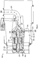
FIG. 2 is a schematic illustration of a fan of an aircraft that may incorporate embodiments of the present disclosure; -
FIG. 3 is a schematic illustration of a fan of an aircraft illustrating a cooling configuration in accordance with an embodiment of the present disclosure; and -
FIG. 4 is a schematic diagram of an aircraft system arrangement in accordance with an embodiment of the present disclosure. -
FIGS. 1A-1B are schematic illustrations of anaircraft 101 that can employ one or more embodiments of the present disclosure. As shown inFIGS. 1A-1B , theaircraft 101 includesbays 103 beneath a center wing box. Thebays 103 can contain and/or support one or more components of theaircraft 101. For example, in some configurations, theaircraft 101 can include environmental control systems and/or fuel inerting systems within thebay 103. As shown inFIG. 1B , thebay 103 includesbay doors 105 that enable installation and access to one or more components (e.g., environmental control systems, fuel inerting systems, etc.). During operation of environmental control systems and/or fuel inerting systems of theaircraft 101, air that is external to theaircraft 101 can flow into one or more environmental control systems within thebay doors 105 through one or moreram air inlets 107. The air may then flow through the environmental control systems to be processed and supplied to various components or locations within the aircraft 101 (e.g., passenger cabin, fuel inerting systems, etc.). Some air may be exhausted through one or more ramair exhaust outlets 109. - Also shown in
FIG. 1A , theaircraft 101 includes one ormore engines 111. Theengines 111 are typically mounted on wings of theaircraft 101 but may be located at other locations depending on the specific aircraft configuration. In some aircraft configurations, air can be bled from theengines 111 and supplied to environmental control systems and/or fuel inerting systems, as will be appreciated by those of skill in the art. Theengines 111 may be configured to generate both thrust for flight and electrical power generation for operation of electronics and/or other components onboard theaircraft 101. - Turning now to
FIG. 2 , an example of anaircraft blower system 200 is shown. Theaircraft blower system 200, also referred to as a fan system, may be arranged onboard an aircraft to provide cooling air for various auxiliary systems, such as environmental control systems of the aircraft. Theaircraft blower system 200 includes ahousing 202 with amotor section 204 and afan section 206 arranged within thehousing 202. Amain flow path 208 is defined between themotor section 204 and an interior of thehousing 202 with thefan section 206 arranged at aninlet side 232 of theaircraft blower system 200. - The
motor section 204 includes astator 210 and a rotor 212, with the rotor 212 coupled to ashaft 214. Thefan section 206 includesfan blades 216 that are coupled to theshaft 214 such that rotation of theshaft 214 causes rotation of thefan blades 216. Theaircraft blower system 200 includes a number of foil-type bearings arranged about theshaft 214. For example, as shown,journal bearings 218 may be arranged along theshaft 214 and thrustbearings 220 may be arranged about a fan disk that supports thefan blades 216. In this illustrative configuration there are two sets ofjournal bearings 218 and two sets ofthrust bearings 220. It will be appreciated that aircraft blower systems may include more or a smaller number of bearings and/or arranged in different locations, without departing from the scope of the present disclosure. - The rotor 212, the
stator 210, and thebearings FIG. 2 , a coolingair conduit 222 is arranged to supply a coolingair 224 to components of theaircraft blower system 200. The coolingair 224 may be sourced from a coolingair supply 226, such as a ram air inlet (e.g., as shown inFIG. 1B ). The coolingair 224 sourced from a ram air inlet has relatively low pressure due to that fact that the ram air is scooped from ambient air external to the aircraft. - The cooling
air 224 may separate into multiple cooling flows within themotor section 204. For example, amotor cooling flow 228 will be directed through and around components of the motor (e.g., the rotor 212 and the stator 210). A portion of the coolingair 224 will be directed into and/or along theshaft 214 to form a bearing cooling flow 230. The bearing cooling flow 230 and themotor cooling flow 228 will merge at aninlet side 232 of theaircraft blower system 200 and enter themain flow path 208 proximate thefan blades 216. - In this configuration, the bearing cooling flow 230 is supplied from the same source (cooling air source 226) as the source for the
motor cooling flow 228. As noted, this is typically sourced from a ram air inlet of the aircraft, and thus is a low pressure source. This configuration of an aircraft blower system is conventionally used in aircraft environmental control systems. However, there is a need to use such blowers as engine accessories to flow cool air through components, including but not limited to, oil coolers, electronics, increased capacity-nitrogen generation systems, and environmental control systems. Due to high vibration loads and bearing cooling requirements, it may be required that a high-pressure air source is employed for bearing cooling. However, high pressure engine air is too hot to cool the bearings and thus a mechanism for employing high pressure cooling air is desirable. - Turning now to
FIG. 3 , a schematic illustration of anaircraft blower system 300 in accordance with an embodiment of the present disclosure is shown. Theaircraft blower system 300, also referred to as a fan system, may be arranged onboard an aircraft to provide cooling air for various auxiliary systems, such as environmental control systems of the aircraft. Theaircraft blower system 300 includes ahousing 302 with amotor section 304 and afan section 306 arranged within thehousing 302. Theaircraft blower system 300 includes foil-type bearings 308 (e.g., journal bearings and thrust bearings) similar to that shown and described above, for example. - In this embodiment, the cooling scheme is different in that a high pressure source is employed to provide high pressure cooling air to the bearings of the system. To achieve this, in this embodiment, a high
pressure air source 310 is tapped within the aircraft to provide high pressure air sufficient to address high vibration loads of theaircraft blower system 300. For example, such increase pressure can provide improved load capacity by minimizing the impacts of vibrations of individual component and between components of the system. The highpressure air source 310 may be a compressor section (e.g., low pressure compressor stage of a gas turbine engine).High pressure air 312 from the highpressure air source 310 may be at an elevated temperature due to compression from the compressor of the gas turbine engine. As such, thehigh pressure air 312 must be cooled prior to being supplied and form abearing cooling flow 314. To reduce the temperature of thehigh pressure air 312, aheat exchanger 316 may be arranged within amain flow path 318 of theaircraft blower system 300. Theheat exchanger 316 is configured to allow thermal interaction between thehigh pressure air 312 and the cooler air within themain flow path 318 to thus lower a temperature of thehigh pressure air 312. The cooledhigh pressure air 312 will then flow into and/or around ashaft 320 of theaircraft blower system 300. - As shown, a low
pressure air source 322 may be used similar to the configuration shown inFIG. 2 and provide low pressure cooling air to components of the motor section 304 (e.g., stator and/or rotor). The bearingcooling flow 314 may be supplied through a high pressure coolingair conduit 324 that connects to and/or passes through theheat exchanger 316. Amotor cooling flow 326 may be provided through a low pressure coolingair conduit 328, as shown. - In some non-limiting examples, the high pressure cooling air supplied from the high pressure air source may have a pressure of 15-30 psia and the low pressure cooling air supplied from the low pressure air source may have a pressure of about ambient pressure (e.g., sourced from ram air inlet). In accordance with some embodiments, and for example, the high pressure cooling air configuration can increase the ratio of bearing cooling supply pressure to sea level atmospheric pressure to values in the range of 1.0-2.0 to permit the use of increased power motors to improve performance, and also permit higher operating loads which includes but is not limited to operation at higher speeds and the ability to install fans in high-vibration locations on an aircraft. In accordance with some embodiments, by providing such increased pressures, bearing capacity may increase by about 50% as pressure ratio approaches 2.0. Furthermore, bearing capacity will continue to increase at pressure ratios greater than 2.0, but such increases may be lower level and the rate of increase may become negligible.
- Turning now to
FIG. 4 , a schematic diagram of anaircraft system 400 in accordance with an embodiment of the present disclosure is shown. Theaircraft system 400 includes agas turbine engine 402 and anaircraft blower system 404. Theaircraft blower system 404 may be similar to that shown and described above with respect toFIG. 3 , for example. Thegas turbine engine 402 includes afan section 406, acompressor section 408, acombustor section 410, and aturbine section 412. Thecompressor section 408 includes a lowpressure compressor stage 416 and a highpressure compressor stage 418. In an embodiment of the present disclosure, atap line 420 is configured to extract a portion of air being compressed within thelow compressor stage 418 and direct such extracted air to theaircraft blower system 404. The extracted air will be relatively warm, and thus aheat exchanger 422 may be arranged within theaircraft blower system 404 to cool the extracted air prior to supplying the high pressure air to bearings of theaircraft blower system 404. - Although shown with the
heat exchanger 422 arranged in theaircraft blower system 404, the position thereof is not to be limiting. For example, in some embodiments, the heat exchanger of theaircraft blower system 404 can be located on the outside of an engine casing surrounding an engine core, such as atlocation 424 shown inFIG. 4 . In this configuration, the engine fan flow is used as the heat sink for cooling the bleed air that is then supplied to the bearings of theaircraft blower system 404. - Advantageously, embodiments described herein provide for improved cooling schemes for bearings of aircraft blower systems. A tap line maybe provided to extract a portion of high pressure air from a low pressure compressor stage of a gas turbine engine as a source of high pressure air. This tap line or conduit may be run through a heat exchanger configured to use fan stream air as a heat sink to cool the high pressure air. The high pressure, cooler air that exits the heat exchanger is now a source of bearing cooling air for the aircraft blower system. This high pressure cooling air is provided to enable more demanding fan applications than conventional systems. During operation, when at low pressures, the bearing capacity is reduced and thus high pressure cooling may not be required. However, with higher bearing cooling air supply pressure, the bearings will have increased load capacity. The increase load capacity provided by the increased pressure can lead to an extended range of applications where the aircraft blower system is be exposed to higher loading (vibration, etc.), higher heat loads, increased speeds, aero thrust loads, etc.
- The use of the terms "a," "an," "the," and similar references in the context of description (especially in the context of the following claims) are to be construed to cover both the singular and the plural, unless otherwise indicated herein or specifically contradicted by context. The modifier "about," "substantially," and/or "approximately" used in connection with a quantity is inclusive of the stated value and has the meaning dictated by the context (e.g., it includes the degree of error associated with measurement of the particular quantity). All ranges disclosed herein are inclusive of the endpoints, and the endpoints are independently combinable with each other.
- While the invention has been described in detail in connection with only a limited number of embodiments, it should be readily understood that the invention is not limited to such disclosed embodiments. Rather, the invention can be modified to incorporate any number of variations, alterations, substitutions, combinations, subcombinations, or equivalent arrangements not heretofore described, but which are commensurate with the scope of the invention. Additionally, while various embodiments of the invention have been described, it is to be understood that aspects of the invention may include only some of the described embodiments.
- Accordingly, the present disclosure is not to be seen as limited by the foregoing description but is only limited by the scope of the appended claims.
Claims (11)
- An aircraft blower system (200), the system comprising:a shaft (214);a motor having a stator (210) and a rotor (212), the rotor being operably coupled to the shaft;a fan (206) operably coupled to the shaft and configured to be driven by rotation of the shaft;one or more bearings (220) arranged along the shaft; anda high pressure cooling source configured to supply high pressure air to the one or more bearings.
- The system of claim 1, wherein the high pressure cooling source is a low pressure compressor of a gas turbine engine.
- The system of claim 1 or 2, further comprising:a main flow path (318) defined within the aircraft blower system; anda heat exchanger (316) arranged within the main flow path and configured to receive the high pressure air along one path of the heat exchanger and to receive air flowing through the main flow path along another path of the heat exchanger.
- The system of any of claims 1-3, wherein the one or more bearings (220) are foil bearings.
- The system of any of claims 1-3, wherein the one or more bearings (220) are journal bearings.
- The system of any of claims 1-3, wherein the one or more bearings (220) are thrust bearings.
- The system of any of claims 1-3, wherein the one or more bearings (220) comprise a combination of journal bearings and thrust bearings.
- The system of any preceding claim, further comprising a low pressure cooling source configured to supply low pressure cooling air to the motor.
- The system of claim 8, wherein the low pressure cooling source is a ram air inlet.
- The system of any preceding claim, wherein the high pressure cooling source is configured to supply air having a pressure of 15 psia or greater.
- An aircraft comprising:a gas turbine engine; andan aircraft blower system of any preceding claim.
Applications Claiming Priority (1)
| Application Number | Priority Date | Filing Date | Title |
|---|---|---|---|
| US16/950,019 US11530705B2 (en) | 2020-11-17 | 2020-11-17 | Bearing cooling schemes for aircraft fans |
Publications (2)
| Publication Number | Publication Date |
|---|---|
| EP4001663A1 true EP4001663A1 (en) | 2022-05-25 |
| EP4001663B1 EP4001663B1 (en) | 2026-04-22 |
Family
ID=78621653
Family Applications (1)
| Application Number | Title | Priority Date | Filing Date |
|---|---|---|---|
| EP21204526.4A Active EP4001663B1 (en) | 2020-11-17 | 2021-10-25 | Improved bearing cooling schemes for aircraft fans |
Country Status (2)
| Country | Link |
|---|---|
| US (1) | US11530705B2 (en) |
| EP (1) | EP4001663B1 (en) |
Families Citing this family (4)
| Publication number | Priority date | Publication date | Assignee | Title |
|---|---|---|---|---|
| US12407210B2 (en) | 2023-03-21 | 2025-09-02 | General Electric Company | High heat transfer cryogenic bearing |
| US12173845B1 (en) * | 2023-07-21 | 2024-12-24 | General Electric Company | Bearing lubrication systems and methods for operating the same |
| US12531454B2 (en) | 2023-08-29 | 2026-01-20 | Hamilton Sundstrand Corporation | Air cooled electric motor having an increased airflow and a method for increasing the airflow therein |
| US12504016B2 (en) | 2024-02-01 | 2025-12-23 | Hamilton Sundstrand Corporation | Bearing cooling flow path for a cabin air compressor |
Citations (3)
| Publication number | Priority date | Publication date | Assignee | Title |
|---|---|---|---|---|
| US20060061221A1 (en) * | 2004-09-22 | 2006-03-23 | Mcauliffe Christopher | Integral motor and air bearing cooling path |
| EP2407380A2 (en) * | 2010-07-16 | 2012-01-18 | Hamilton Sundstrand Corporation | Cabin air compressor motor cooling |
| US20170167292A1 (en) * | 2015-12-14 | 2017-06-15 | Hamilton Sundstrand Corporation | Variable-sized cooling air flow path |
Family Cites Families (12)
| Publication number | Priority date | Publication date | Assignee | Title |
|---|---|---|---|---|
| US4542623A (en) | 1983-12-23 | 1985-09-24 | United Technologies Corporation | Air cooler for providing buffer air to a bearing compartment |
| US4645415A (en) * | 1983-12-23 | 1987-02-24 | United Technologies Corporation | Air cooler for providing buffer air to a bearing compartment |
| US7988426B2 (en) | 2005-01-10 | 2011-08-02 | Honeywell International Inc. | Compressor ported shroud for foil bearing cooling |
| US20130192240A1 (en) | 2012-01-31 | 2013-08-01 | Peter M. Munsell | Buffer system for a gas turbine engine |
| US10018116B2 (en) | 2012-01-31 | 2018-07-10 | United Technologies Corporation | Gas turbine engine buffer system providing zoned ventilation |
| US9914542B2 (en) | 2013-10-14 | 2018-03-13 | Hamilton Sundstrand Corporation | Ram air fan housing |
| FR3017656B1 (en) * | 2014-02-17 | 2016-03-11 | Airbus Operations Sas | TURBOREACTOR COMPRISING A SAMPLING SYSTEM FOR TAKING AIR INTO THE TURBOREACTOR |
| US20160363003A1 (en) * | 2014-08-15 | 2016-12-15 | Gen Electric | Mechanical drive architectures with hybrid-type low-loss bearings and low-density materials |
| GB201512494D0 (en) * | 2015-07-17 | 2015-08-19 | Rolls Royce Plc And Rolls Royce Deutschland Ltd & Co Kg | Gas turbine engine |
| US10308366B2 (en) * | 2016-08-22 | 2019-06-04 | General Electric Company | Embedded electric machine |
| EP3409903B1 (en) | 2017-06-01 | 2021-09-01 | General Electric Company | Gas turbine system with an intercooler providing cooled fluid as bearing pressurization fluid |
| US11359635B2 (en) * | 2019-04-14 | 2022-06-14 | Hamilton Sundstrand Corporation | Power modules with regenerative compressor wheels |
-
2020
- 2020-11-17 US US16/950,019 patent/US11530705B2/en active Active
-
2021
- 2021-10-25 EP EP21204526.4A patent/EP4001663B1/en active Active
Patent Citations (3)
| Publication number | Priority date | Publication date | Assignee | Title |
|---|---|---|---|---|
| US20060061221A1 (en) * | 2004-09-22 | 2006-03-23 | Mcauliffe Christopher | Integral motor and air bearing cooling path |
| EP2407380A2 (en) * | 2010-07-16 | 2012-01-18 | Hamilton Sundstrand Corporation | Cabin air compressor motor cooling |
| US20170167292A1 (en) * | 2015-12-14 | 2017-06-15 | Hamilton Sundstrand Corporation | Variable-sized cooling air flow path |
Also Published As
| Publication number | Publication date |
|---|---|
| US11530705B2 (en) | 2022-12-20 |
| EP4001663B1 (en) | 2026-04-22 |
| US20220154723A1 (en) | 2022-05-19 |
Similar Documents
| Publication | Publication Date | Title |
|---|---|---|
| EP4001663B1 (en) | Improved bearing cooling schemes for aircraft fans | |
| US5490645A (en) | Fully integrated environmental and secondary power system | |
| US11092031B2 (en) | Drive system for an aircraft | |
| EP1895141B1 (en) | Splitter for a turbo-fan engine | |
| EP1642828B1 (en) | Ram fan system for an aircraft environmental control system | |
| US9109464B2 (en) | Distributed lubrication system | |
| KR101812829B1 (en) | Method for optimizing the operability of an aircraft propulsive unit, and self-contained power unit for implementing same | |
| EP2584173B1 (en) | Gas Turbine Engine | |
| US6151909A (en) | Two spool air cycle machine having concentric shafts | |
| US20120011878A1 (en) | Cabin air compressor motor cooling | |
| EP2971664B2 (en) | Geared turbofan engine and cooling method thereof | |
| EP2322430A1 (en) | Environmental control system | |
| US11897618B2 (en) | Cabin air compressor with liquid cooled passage formed in the case | |
| US11629637B2 (en) | Supercritical carbon dioxide-cooled generator and turbine | |
| US11658542B2 (en) | Cabin air compressor with liquid cooled jacket | |
| EP0975862B1 (en) | Improved integrated environmental and secondary power system | |
| EP3677508A1 (en) | Concentric turbine condensing cycle | |
| US11994066B2 (en) | Thermal management system | |
| US20100326049A1 (en) | Cooling systems for rotorcraft engines | |
| EP4389610A1 (en) | Oxygen-depleted vapor phase motor cooling | |
| US20250341345A1 (en) | Multi-stage rotor for air cycle machine | |
| US20240263847A1 (en) | Motor integrated auxiliary bearings for aircraft machines | |
| CN121986209A (en) | Method for heating fuel in a turbine fuel supply system |
Legal Events
| Date | Code | Title | Description |
|---|---|---|---|
| PUAI | Public reference made under article 153(3) epc to a published international application that has entered the european phase |
Free format text: ORIGINAL CODE: 0009012 |
|
| STAA | Information on the status of an ep patent application or granted ep patent |
Free format text: STATUS: THE APPLICATION HAS BEEN PUBLISHED |
|
| AK | Designated contracting states |
Kind code of ref document: A1 Designated state(s): AL AT BE BG CH CY CZ DE DK EE ES FI FR GB GR HR HU IE IS IT LI LT LU LV MC MK MT NL NO PL PT RO RS SE SI SK SM TR |
|
| STAA | Information on the status of an ep patent application or granted ep patent |
Free format text: STATUS: REQUEST FOR EXAMINATION WAS MADE |
|
| 17P | Request for examination filed |
Effective date: 20221122 |
|
| RBV | Designated contracting states (corrected) |
Designated state(s): AL AT BE BG CH CY CZ DE DK EE ES FI FR GB GR HR HU IE IS IT LI LT LU LV MC MK MT NL NO PL PT RO RS SE SI SK SM TR |
|
| STAA | Information on the status of an ep patent application or granted ep patent |
Free format text: STATUS: EXAMINATION IS IN PROGRESS |
|
| 17Q | First examination report despatched |
Effective date: 20240426 |
|
| GRAP | Despatch of communication of intention to grant a patent |
Free format text: ORIGINAL CODE: EPIDOSNIGR1 |
|
| STAA | Information on the status of an ep patent application or granted ep patent |
Free format text: STATUS: GRANT OF PATENT IS INTENDED |
|
| RIC1 | Information provided on ipc code assigned before grant |
Ipc: F04D 29/58 20060101AFI20251105BHEP Ipc: F04D 25/06 20060101ALI20251105BHEP Ipc: B64D 13/00 20060101ALI20251105BHEP Ipc: F04D 19/00 20060101ALI20251105BHEP Ipc: F04D 29/053 20060101ALI20251105BHEP Ipc: F04D 29/057 20060101ALI20251105BHEP Ipc: B64D 37/32 20060101ALN20251105BHEP |
|
| INTG | Intention to grant announced |
Effective date: 20251117 |
|
| GRAS | Grant fee paid |
Free format text: ORIGINAL CODE: EPIDOSNIGR3 |
|
| GRAA | (expected) grant |
Free format text: ORIGINAL CODE: 0009210 |
|
| STAA | Information on the status of an ep patent application or granted ep patent |
Free format text: STATUS: THE PATENT HAS BEEN GRANTED |
|
| AK | Designated contracting states |
Kind code of ref document: B1 Designated state(s): AL AT BE BG CH CY CZ DE DK EE ES FI FR GB GR HR HU IE IS IT LI LT LU LV MC MK MT NL NO PL PT RO RS SE SI SK SM TR |
|
| REG | Reference to a national code |
Ref country code: CH Ref legal event code: F10 Free format text: ST27 STATUS EVENT CODE: U-0-0-F10-F00 (AS PROVIDED BY THE NATIONAL OFFICE) Effective date: 20260422 Ref country code: GB Ref legal event code: FG4D |