EP4001644A1 - System for power generation using gravity - Google Patents
System for power generation using gravity Download PDFInfo
- Publication number
- EP4001644A1 EP4001644A1 EP20839645.7A EP20839645A EP4001644A1 EP 4001644 A1 EP4001644 A1 EP 4001644A1 EP 20839645 A EP20839645 A EP 20839645A EP 4001644 A1 EP4001644 A1 EP 4001644A1
- Authority
- EP
- European Patent Office
- Prior art keywords
- spherical bodies
- ramp
- fall
- power generation
- lifting
- Prior art date
- Legal status (The legal status is an assumption and is not a legal conclusion. Google has not performed a legal analysis and makes no representation as to the accuracy of the status listed.)
- Withdrawn
Links
Images
Classifications
-
- F—MECHANICAL ENGINEERING; LIGHTING; HEATING; WEAPONS; BLASTING
- F03—MACHINES OR ENGINES FOR LIQUIDS; WIND, SPRING, OR WEIGHT MOTORS; PRODUCING MECHANICAL POWER OR A REACTIVE PROPULSIVE THRUST, NOT OTHERWISE PROVIDED FOR
- F03G—SPRING, WEIGHT, INERTIA OR LIKE MOTORS; MECHANICAL-POWER PRODUCING DEVICES OR MECHANISMS, NOT OTHERWISE PROVIDED FOR OR USING ENERGY SOURCES NOT OTHERWISE PROVIDED FOR
- F03G3/00—Other motors, e.g. gravity or inertia motors
-
- H—ELECTRICITY
- H02—GENERATION; CONVERSION OR DISTRIBUTION OF ELECTRIC POWER
- H02K—DYNAMO-ELECTRIC MACHINES
- H02K53/00—Alleged dynamo-electric perpetua mobilia
-
- F—MECHANICAL ENGINEERING; LIGHTING; HEATING; WEAPONS; BLASTING
- F03—MACHINES OR ENGINES FOR LIQUIDS; WIND, SPRING, OR WEIGHT MOTORS; PRODUCING MECHANICAL POWER OR A REACTIVE PROPULSIVE THRUST, NOT OTHERWISE PROVIDED FOR
- F03G—SPRING, WEIGHT, INERTIA OR LIKE MOTORS; MECHANICAL-POWER PRODUCING DEVICES OR MECHANISMS, NOT OTHERWISE PROVIDED FOR OR USING ENERGY SOURCES NOT OTHERWISE PROVIDED FOR
- F03G7/00—Mechanical-power-producing mechanisms, not otherwise provided for or using energy sources not otherwise provided for
- F03G7/10—Alleged perpetua mobilia
- F03G7/104—Alleged perpetua mobilia continuously converting gravity into usable power
- F03G7/107—Alleged perpetua mobilia continuously converting gravity into usable power using an imbalance for increasing torque or saving energy
Definitions
- the object of the present invention application is to register a system for power generation using gravity which incorporates significant innovations and advantages over the techniques used up until now.
- the invention proposes the development of a system for power generation using gravity which, as a result of its particular arrangement, allows generating a movement connected to the action of gravity and using said movement to generate electric power, and all this without requiring fuel consumption.
- the present invention contributes to solving and providing an answer to the present problems as it allows generating a movement connected to the action of gravity and using said movement to generate electric power, and all this without requiring fuel consumption.
- the present invention has been developed for the purpose of providing a system for power generation using gravity, which is essentially characterised in that it comprises a plurality of spherical bodies, a storage platform for storing the spherical bodies, a ramp fall system for the spherical bodies to fall by means of gravity, a lifting system for lifting the spherical bodies, an electric power generator, movement transmission means for transmitting movement between the ramp fall system and the electric power generator.
- the ramp fall system for the fall of the spherical bodies comprises at least one mechanism of chains, pinions and bolts which is disposed and positioned longitudinally on the slope of a ramp and the storage platform for storing the spherical bodies furthermore being disposed on the upper level of said ramp, and the same mechanism of chains, pinions and bolts being able to receive the spherical bodies individually from the storage platform and position them between the successive bolts and the spherical bodies being disposed on the slope of the ramp at the same time, and the same mechanism being able to receive rectilinear movement in the chain communicated from the spherical bodies when they fall and roll along the slope of the ramp.
- the lifting system for lifting the spherical bodies is able to receive the balls released from the ramp fall system after said spherical bodies have fallen and rolled along the slope of the ramp, and able to lift and place the same spherical bodies on the storage platform for storing the spherical bodies.
- the movement transmission means mechanically and simultaneously connected to the ramp fall system and the electric power generator are able to receive the rotational movement of the pinions of the chain generated by the falling and rolling of the spherical bodies, and to adapt and communicate said rotational movement to the electric generator, the ramp fall system incorporating a manually or automatically actuated locking mechanism that is able to prevent the movement of the mechanism of chains, pinions and bolts.
- the ramp fall system for the fall of the spherical bodies comprises at least one mechanism of chains, pinions and bolts, with the ramp, on which each mechanism is disposed, being made up of guide-like longitudinal profiles on which the spherical bodies can roll by means of gravity; each mechanism being provided with a pair of chains arranged symmetrically with respect to one another and extending along the length of the profiles, the chains being connected to one another by bolts such that the movement of each chain is integral, and with each chain meshing with a rolling pinion disposed at each end of the profiles.
- the system for power generation using gravity of the invention has a plurality of mechanisms of chains, pinions and bolts, said mechanisms of chains, pinions and bolts being grouped and positioned in pairs; the pinion of a chain which is disposed at the upper end of the profile of the ramp being connected by means of a secondary shaft with another pinion of the other corresponding mechanism of the same pair, the movement of both pinions thereby being integral with one another; each secondary shaft being mechanically communicated in the rotation thereof, in a specific ratio of rotation, with one and the same main shaft, which is in turn mechanically connected to the movement transmission means.
- the lifting system for lifting the spherical bodies is disposed on an independent mobile structure, and incorporates a base where the spherical bodies are placed and lifting means for lifting the base which are capable of lifting and lowering said base between the upper level and the lower level determined by the ramp; it also incorporates a weight sensor for detecting the weight of the spherical bodies placed in the base, said weight sensor being connected in data communication with the lifting means; it also incorporates a cushioning system adapted to the impact of the spherical bodies; the base being able to receive the spherical bodies after they have fallen and rolled along the slope of the ramp when it is on the lower level determined by the ramp; the same base being able to transfer the same spherical bodies to the storage platform for storing the spherical bodies when it is on the upper level determined by the ramp.
- the storage platform for storing the spherical bodies is fixed with respect to the ground and has a parallelogrammatic geometry with 4 m x 2 m proportions; it has a variable inclination measured from the region thereof for receiving the spherical bodies from the lifting system to the other region thereof for delivering the same spherical bodies to the ramp fall system for the fall of the balls; it also has one and the same inclination towards the left and right with respect to the direction in which the spherical bodies exit to the ramps.
- the movement transmission means for transmitting movement between the ramp fall system and the electric power generator are mechanically connected in the rotation thereof with the main shaft and with a specific ratio of rotation.
- the ratio of rotation with the main shaft is 1 to 1500.
- the ratio of rotation of each secondary shaft with the main shaft is 1 to 3.5.
- the movement transmission means for transmitting movement between the ramp fall system and the electric power generator comprise a set of gears.
- the movement transmission means for transmitting movement between the ramp fall system and the electric power generator comprise a set of pulleys, pinions and belts.
- each mechanism of chains, pinions and bolts comprises 33 bolts.
- the spherical bodies are made of steel with a lead-filled interior having an outer diameter of 180 mm and a weight of 38 kg.
- the profiles making up the ramps have a slope inclination comprised in a range of 60-85%.
- the system for power generation using gravity incorporates a channelling track which is supported on the ground and disposed between the ramp fall system and the lifting system, and is capable of channelling the spherical bodies coming from each mechanism of chains, pinions and bolts to the lifting system, having for such purpose an inclination of 2%, and said channelling track having a passage barrier before the lifting system, disposed such that it can retain the spherical bodies coming from the ramp fall system before they enter the lifting system.
- the system for power generation using gravity incorporates a gateway disposed over the ramp fall system, and is capable of channelling the spherical bodies coming from the base to the storage platform.
- the system for power generation using gravity incorporates a mechanism for tensioning the mechanism of chains, pinions and bolts.
- the system for power generation using gravity incorporates electric current accumulation means.
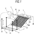
- the system for power generation using gravity of the proposed invention comprises a plurality of spherical bodies 1, a storage platform 2 for storing the spherical bodies, a ramp fall system 3 for the balls 1 to fall by means of gravity, a lifting system 4 for lifting the spherical bodies 1, an electric power generator 6, and movement transmission means 5 for transmitting movement between the ramp fall system 3 and the electric power generator 6.
- the ramp fall system 3 for the fall of the spherical bodies 1 has a plurality of mechanisms 30 of chains, pinions and bolts.
- Each mechanism 30 is disposed and positioned longitudinally on the slope of a ramp which is made up of profiles 34, the storage platform 2 for storing the spherical bodies 1 being furthermore fixed on the ground and disposed on the upper level of said ramp.
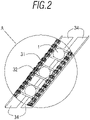
- each mechanism 30 is provided with a pair of chains 31 arranged symmetrically with respect to one another and extending along the length of the ramp, the chains 31 being connected to one another by bolts 32 such that the movement of each chain 31 is integral, and with each chain 31 meshing with a rolling pinion 33 disposed at each end of the ramp, i.e., of the profiles 34, and therefore at different heights.
- each pair of chains 31 incorporates 33 bolts 32.
- the same mechanism 30 of chains, pinions and bolts is able to receive the spherical bodies 1 individually from the mentioned storage platform 2, as well as position them between the successive bolts 32 of the chains 31, and the spherical bodies 1 are disposed at the same time on the slope of the ramp formed by profiles 34, as can be seen in enlarged detail A of Figure 2 .
- the ramp on which each mechanism 30 of each pair is disposed is made up of guide-like longitudinal profiles 34 on which the spherical bodies 1 can roll by means of gravity.
- said profiles 34 are depicted in a mechanism 30 of chains, pinions and bolts.
- Each of the ramps, i.e., the profiles 34 has a slope inclination comprised in a range of 60-85%, more specifically 80%.
- each of the spherical bodies 1 are made of steel with a lead-filled interior having an outer diameter of 180 mm and a weight of 38 kg.
- an arrangement of 15 spherical bodies, 1 in each mechanism 30 of chains, pinions and bolts. is optimal for the proper operation of the system for power generation using gravity of the invention.
- the slope of the ramp causes the spherical bodies 1 to roll down the same ramp by means of gravity, and this means that with the spherical bodies 1 in turn being disposed between the bolts 32, the chain 31 receives a rectilinear movement from the same spherical bodies 1, which entails the rotation of the pinions 33 thereof, as can be deduced from Figures 1 and 2 .
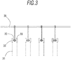
- Each secondary shaft 35 of each pair of mechanisms of chains, pinions and bolts is mechanically connected in the rotation thereof, in a ratio of rotation of 1 to 3.5, with one and the same main shaft 36, said main shaft 36 in turn being positioned by means of bearings in the storage platform 2 for storing the spherical bodies 1.
- the system for power generation using gravity of the invention incorporates a mechanism for tensioning the mechanism 30 of chains, pinions and bolts which provides the required tension to the chains 31 so that they maintain a suitable linearity during the movement thereof received from the spherical bodies 1 through the bolts 32.
- the system for power generation using gravity of the invention incorporates a channelling track 7 supported on the ground, which is disposed between the ramp fall system 3 and the lifting system 4, and is capable of channelling the spherical bodies 1 coming from each mechanism 30 of chains, pinions and bolts to the lifting system 4, having for such purpose an inclination of 2%, and with a funnel-like channelling geometry for channelling the spherical bodies 1 from the ramp fall system 3 to the lifting system 4.
- the channelling track has a passage barrier before the lifting system 4, disposed such that it can retain the spherical bodies 1 coming from the ramp fall system 3 before they enter the lifting system 4.
- the lifting system 4 for lifting the spherical bodies 1 is disposed on an independent mobile structure, and is able to receive, at the same time, the spherical bodies 1 released from the ramp fall system 3 after said spherical bodies 1 have fallen and rolled along the slope of the ramp.
- This lifting system 4 may comprise a platform lifting element that is commercially available so it will not be described in detail.
- the same lifting system 4 for lifting the spherical bodies 1 is able to lift and place the spherical bodies 1 onto the storage platform 2 for storing the spherical bodies 1.
- the spherical bodies 1 reach the lifting system 4, rolling by gravity through the channelling track 7.
- the lifting system 4 incorporates a base 41.
- the spherical bodies 1 collected from the ramp are placed in said base 41.
- lifting means for lifting the base 41 which are capable of lifting and lowering said base 41 between the upper level and the lower level determined by the ramp, and as indicated by the arrows of Figure 1 .
- Such lifting means can comprise a plurality of vertically disposed guiding profiles and an electric motor 42 governed by a control unit, the electric current supply source of this motor being electrically connected with the generator 6 by means of electrical connections (depicted by means of discontinuous lines in Figures 1 and 3 ).
- Figure 1 shows the base 41 of the lifting system 4 on the lower level of the ramp, receiving the spherical bodies 1.
- the lifting system 4 for lifting the balls 1 also incorporates a weight sensor 43 for detecting the weight of the spherical bodies 1 placed in the base 41 thereof.
- Said weight sensor 43 is connected in data communication with the mentioned lifting means, so when the base 1 already receives a specific weight according to the amount of spherical bodies 1 received, the lifting means lift the base 1 from the lower level to the upper level of the ramp.
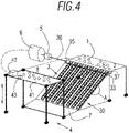
- Figure 4 shows the base 41 of the lifting system 4 on the upper level of the ramp, and delivering the spherical bodies 1 to the storage platform 2.
- the lifting system 4 for lifting the spherical bodies 1 also incorporates a cushioning system to reduce the effect of the impact of the spherical bodies 1 as they reach the base 41.
- the base 41 is able to receive the spherical bodies 1 after they have fallen and rolled along the slope of the ramp when it is on the lower level determined by the ramp, as schematically depicted in Figure 1 , and also to transfer the balls 1 to the storage platform 2 for storing the spherical bodies 1 when it is on the upper level determined by the same ramp, as also schematically depicted in Figure 4 .
- a gateway 8 disposed over the ramp fall system 3 and depicted with dashed lines in Figures 1 and 3 is provided to that end.
- the storage platform 2 has a parallelogrammatic geometry measuring 4 m x 2 m, with an inclination of 2% towards the ramp fall system 3, to allow the passage of the spherical bodies 1 to the ramp fall system 3. Nevertheless, said inclination may be variable and adjustable according to specific operation needs, for example, between 2% and 5%.
- the movement transmission means 5 are mechanically and simultaneously connected to the ramp fall system 3 and the electric power generator 6, and are able to receive the rotational movement of the pinions 33 of the chain 31 generated by the falling and rolling of the spherical bodies 1, and to adapt and communicate said rotational movement to the electric generator 6 by means of a transmission shaft 37.
- the movement transmission means 5 are mechanically connected in the rotation thereof with the aforementioned main shaft 36, and with a ratio of rotation of 1 to 1500.
- the mentioned movement transmission means 5 for transmitting movement between the ramp fall system 3 and the electric power generator 6 may comprise a set of gears, and in other preferred embodiments may comprise a set of pulleys, pinions and toothed belts due to their properties of being silent, as can be schematically seen in Figure 4 .
- the ramp fall system 3 incorporates a manually or automatically actuated locking mechanism 37 that is able to prevent the movement of the mechanism 30 of chains, pinions and bolts.
- spherical bodies 1 In the operation of the system for power generation using gravity of the invention, spherical bodies 1 must be initially loaded in the storage platform 2, and to that end, the movement of the mechanisms 30 of chains, pinions and bolts must furthermore be blocked by means of the aforementioned locking mechanism 37, to thereby allow spherical bodies 1 to be loaded in the storage platform 2 without the spherical bodies 1 moving out through the mechanism 30 of chains, pinions and bolts.
- the system for power generation using gravity of the invention incorporates electric current accumulation means, for example, a battery, which is electrically connected to the lifting system 4. This can be useful to provide the power required for starting the operation of the lifting system 4.
- electric current accumulation means for example, a battery
- An extremely useful advantage of the system for power generation using gravity of the invention can be, for example, the use thereof in a service for generating electric power in the same way as is normally provided by a generator set.
Landscapes
- Engineering & Computer Science (AREA)
- Chemical & Material Sciences (AREA)
- Combustion & Propulsion (AREA)
- Mechanical Engineering (AREA)
- General Engineering & Computer Science (AREA)
- Power Engineering (AREA)
- Other Liquid Machine Or Engine Such As Wave Power Use (AREA)
Abstract
Description
- The object of the present invention application is to register a system for power generation using gravity which incorporates significant innovations and advantages over the techniques used up until now.
- More specifically, the invention proposes the development of a system for power generation using gravity which, as a result of its particular arrangement, allows generating a movement connected to the action of gravity and using said movement to generate electric power, and all this without requiring fuel consumption.
- Many and varied systems for using energy to obtain electric power are known in the current state of the art.
- Despite many of them being extremely useful, all of them, however, require supplying a certain type of fuel, particularly fossil fuel, for their operation, with the environmental drawbacks that this entails.
- Progressive and constant increase in power consumption, both locally and globally, is an indisputable fact today.
- All this responds to several factors at the same time: demographic growth of the population, access of a larger proportion of the population to new amnesties, and therefore energy demand (washing machines, heating, televisions, etc.), use of services and new technologies that did not exist previously (the Internet, etc.), global increase in industrialisation, etc.
- Therefore, there is need to meet the growing energy demand taking place at the domestic and industrial level both locally and globally, and to thereby find a sustainable, limitless, clean production system that is free from waste and residues.
- This has led to growing awareness in this regard, both among the society and on the part of public authorities.
- In addition to what has been explained above, other than the solutions already existing today, the pressing need for new energy alternatives under study which are fully compatible with sustainable environmental development and do not entail an environmental burden for future generations, in addition to entailing considerable economic savings in energy consumption, should also be added.
- It should be mentioned that, although there can be found on the market many types and models of electric power-generating apparatus and devices which use different physical principles to actuate a mechanism which produces a movement from which the rotation of a shaft is used to transform it into electric power, the existence of a system that has technical, structural, and constitutive features similar to those herein claimed, or using a method similar to the one described, is unheard of.
- The present invention contributes to solving and providing an answer to the present problems as it allows generating a movement connected to the action of gravity and using said movement to generate electric power, and all this without requiring fuel consumption.
- The present invention has been developed for the purpose of providing a system for power generation using gravity, which is essentially characterised in that it comprises a plurality of spherical bodies, a storage platform for storing the spherical bodies, a ramp fall system for the spherical bodies to fall by means of gravity, a lifting system for lifting the spherical bodies, an electric power generator, movement transmission means for transmitting movement between the ramp fall system and the electric power generator.
- The ramp fall system for the fall of the spherical bodies comprises at least one mechanism of chains, pinions and bolts which is disposed and positioned longitudinally on the slope of a ramp and the storage platform for storing the spherical bodies furthermore being disposed on the upper level of said ramp, and the same mechanism of chains, pinions and bolts being able to receive the spherical bodies individually from the storage platform and position them between the successive bolts and the spherical bodies being disposed on the slope of the ramp at the same time, and the same mechanism being able to receive rectilinear movement in the chain communicated from the spherical bodies when they fall and roll along the slope of the ramp.
- The lifting system for lifting the spherical bodies is able to receive the balls released from the ramp fall system after said spherical bodies have fallen and rolled along the slope of the ramp, and able to lift and place the same spherical bodies on the storage platform for storing the spherical bodies.
- The movement transmission means mechanically and simultaneously connected to the ramp fall system and the electric power generator are able to receive the rotational movement of the pinions of the chain generated by the falling and rolling of the spherical bodies, and to adapt and communicate said rotational movement to the electric generator, the ramp fall system incorporating a manually or automatically actuated locking mechanism that is able to prevent the movement of the mechanism of chains, pinions and bolts.
- According to another aspect of the invention, the ramp fall system for the fall of the spherical bodies comprises at least one mechanism of chains, pinions and bolts, with the ramp, on which each mechanism is disposed, being made up of guide-like longitudinal profiles on which the spherical bodies can roll by means of gravity; each mechanism being provided with a pair of chains arranged symmetrically with respect to one another and extending along the length of the profiles, the chains being connected to one another by bolts such that the movement of each chain is integral, and with each chain meshing with a rolling pinion disposed at each end of the profiles.
- Furthermore, the system for power generation using gravity of the invention has a plurality of mechanisms of chains, pinions and bolts, said mechanisms of chains, pinions and bolts being grouped and positioned in pairs; the pinion of a chain which is disposed at the upper end of the profile of the ramp being connected by means of a secondary shaft with another pinion of the other corresponding mechanism of the same pair, the movement of both pinions thereby being integral with one another; each secondary shaft being mechanically communicated in the rotation thereof, in a specific ratio of rotation, with one and the same main shaft, which is in turn mechanically connected to the movement transmission means.
- In turn, in the system for power generation using gravity of the invention, the lifting system for lifting the spherical bodies is disposed on an independent mobile structure, and incorporates a base where the spherical bodies are placed and lifting means for lifting the base which are capable of lifting and lowering said base between the upper level and the lower level determined by the ramp; it also incorporates a weight sensor for detecting the weight of the spherical bodies placed in the base, said weight sensor being connected in data communication with the lifting means; it also incorporates a cushioning system adapted to the impact of the spherical bodies; the base being able to receive the spherical bodies after they have fallen and rolled along the slope of the ramp when it is on the lower level determined by the ramp; the same base being able to transfer the same spherical bodies to the storage platform for storing the spherical bodies when it is on the upper level determined by the ramp.
- In turn, the storage platform for storing the spherical bodies is fixed with respect to the ground and has a parallelogrammatic geometry with 4 m x 2 m proportions; it has a variable inclination measured from the region thereof for receiving the spherical bodies from the lifting system to the other region thereof for delivering the same spherical bodies to the ramp fall system for the fall of the balls; it also has one and the same inclination towards the left and right with respect to the direction in which the spherical bodies exit to the ramps.
- Additionally, in the system for power generation using gravity, the movement transmission means for transmitting movement between the ramp fall system and the electric power generator are mechanically connected in the rotation thereof with the main shaft and with a specific ratio of rotation.
- Alternatively, in the system for power generation using gravity, the ratio of rotation with the main shaft is 1 to 1500.
- Alternatively, in the system for power generation using gravity, the ratio of rotation of each secondary shaft with the main shaft is 1 to 3.5.
- Additionally, in the system for power generation using gravity, the movement transmission means for transmitting movement between the ramp fall system and the electric power generator comprise a set of gears.
- Additionally, in the system for power generation using gravity, the movement transmission means for transmitting movement between the ramp fall system and the electric power generator comprise a set of pulleys, pinions and belts.
- Alternatively, in the system for power generation using gravity, the mentioned inclinations are 2%.
- Alternatively, in the system for power generation using gravity, each mechanism of chains, pinions and bolts, comprises 33 bolts.
- Alternatively, in the system for power generation using gravity, the spherical bodies are made of steel with a lead-filled interior having an outer diameter of 180 mm and a weight of 38 kg.
- Preferably, in the system for power generation using gravity, the profiles making up the ramps have a slope inclination comprised in a range of 60-85%.
- Additionally, the system for power generation using gravity incorporates a channelling track which is supported on the ground and disposed between the ramp fall system and the lifting system, and is capable of channelling the spherical bodies coming from each mechanism of chains, pinions and bolts to the lifting system, having for such purpose an inclination of 2%, and said channelling track having a passage barrier before the lifting system, disposed such that it can retain the spherical bodies coming from the ramp fall system before they enter the lifting system.
- Preferably, the system for power generation using gravity incorporates a gateway disposed over the ramp fall system, and is capable of channelling the spherical bodies coming from the base to the storage platform.
- Preferably, the system for power generation using gravity incorporates a mechanism for tensioning the mechanism of chains, pinions and bolts.
- Alternatively, the system for power generation using gravity incorporates electric current accumulation means.
- As a result of the present invention, a movement connected to the action of gravity is successfully generated and said movement is used to generate electric power, and all this without requiring the consumption of additional fuel given that the system itself, after unblocking the movement of the spherical bodies, generates sufficient current which will allow powering the lifting system and providing electric current to power electrical devices external to the system of the invention.
- Other features and advantages of the system for power generation using gravity will become apparent from the description of a preferred but not exclusive embodiment illustrated by way of non-limiting example in the attached drawings, in which:
-
-
Figures 1 and4 are schematic views indicating the operation of a preferred embodiment of the system for power generation using gravity of the present invention. -
Figure 2 is a schematic view of an enlarged detail ofFigure 1 . -
Figure 3 is a schematic view of the transmission of rotational movement from ramp fall system to the transmission means. - Figure 5 is a schematic view corresponding to a preferred embodiment of the transmission means.
- As schematically shown in
Figure 1 , the system for power generation using gravity of the proposed invention comprises a plurality ofspherical bodies 1, astorage platform 2 for storing the spherical bodies, aramp fall system 3 for theballs 1 to fall by means of gravity, alifting system 4 for lifting thespherical bodies 1, anelectric power generator 6, and movement transmission means 5 for transmitting movement between theramp fall system 3 and theelectric power generator 6. - In turn, the
ramp fall system 3 for the fall of thespherical bodies 1 has a plurality ofmechanisms 30 of chains, pinions and bolts. Eachmechanism 30 is disposed and positioned longitudinally on the slope of a ramp which is made up ofprofiles 34, thestorage platform 2 for storing thespherical bodies 1 being furthermore fixed on the ground and disposed on the upper level of said ramp. - As can be seen in
Figure 1 and the enlarged detail A ofFigure 2 , eachmechanism 30 is provided with a pair ofchains 31 arranged symmetrically with respect to one another and extending along the length of the ramp, thechains 31 being connected to one another bybolts 32 such that the movement of eachchain 31 is integral, and with eachchain 31 meshing with arolling pinion 33 disposed at each end of the ramp, i.e., of theprofiles 34, and therefore at different heights. In this preferred embodiment, each pair ofchains 31 incorporates 33bolts 32. - The
same mechanism 30 of chains, pinions and bolts is able to receive thespherical bodies 1 individually from the mentionedstorage platform 2, as well as position them between thesuccessive bolts 32 of thechains 31, and thespherical bodies 1 are disposed at the same time on the slope of the ramp formed byprofiles 34, as can be seen in enlarged detail A ofFigure 2 . - The ramp on which each
mechanism 30 of each pair is disposed is made up of guide-likelongitudinal profiles 34 on which thespherical bodies 1 can roll by means of gravity. In enlarged detail A ofFigure 2 , saidprofiles 34 are depicted in amechanism 30 of chains, pinions and bolts. Each of the ramps, i.e., theprofiles 34, has a slope inclination comprised in a range of 60-85%, more specifically 80%. - In this preferred embodiment, and for the excellent performance thereof, each of the
spherical bodies 1 are made of steel with a lead-filled interior having an outer diameter of 180 mm and a weight of 38 kg. Likewise, an arrangement of 15 spherical bodies, 1 in eachmechanism 30 of chains, pinions and bolts. is optimal for the proper operation of the system for power generation using gravity of the invention. - The slope of the ramp causes the
spherical bodies 1 to roll down the same ramp by means of gravity, and this means that with thespherical bodies 1 in turn being disposed between thebolts 32, thechain 31 receives a rectilinear movement from the samespherical bodies 1, which entails the rotation of thepinions 33 thereof, as can be deduced fromFigures 1 and2 . - Each
secondary shaft 35 of each pair of mechanisms of chains, pinions and bolts is mechanically connected in the rotation thereof, in a ratio of rotation of 1 to 3.5, with one and the samemain shaft 36, saidmain shaft 36 in turn being positioned by means of bearings in thestorage platform 2 for storing thespherical bodies 1. - The system for power generation using gravity of the invention incorporates a mechanism for tensioning the
mechanism 30 of chains, pinions and bolts which provides the required tension to thechains 31 so that they maintain a suitable linearity during the movement thereof received from thespherical bodies 1 through thebolts 32. - The system for power generation using gravity of the invention incorporates a
channelling track 7 supported on the ground, which is disposed between theramp fall system 3 and thelifting system 4, and is capable of channelling thespherical bodies 1 coming from eachmechanism 30 of chains, pinions and bolts to thelifting system 4, having for such purpose an inclination of 2%, and with a funnel-like channelling geometry for channelling thespherical bodies 1 from theramp fall system 3 to thelifting system 4. - The channelling track has a passage barrier before the
lifting system 4, disposed such that it can retain thespherical bodies 1 coming from theramp fall system 3 before they enter thelifting system 4. - In turn, the
lifting system 4 for lifting thespherical bodies 1 is disposed on an independent mobile structure, and is able to receive, at the same time, thespherical bodies 1 released from theramp fall system 3 after saidspherical bodies 1 have fallen and rolled along the slope of the ramp. Thislifting system 4 may comprise a platform lifting element that is commercially available so it will not be described in detail. - Like a forklift, the
same lifting system 4 for lifting thespherical bodies 1 is able to lift and place thespherical bodies 1 onto thestorage platform 2 for storing thespherical bodies 1. Thespherical bodies 1 reach thelifting system 4, rolling by gravity through thechannelling track 7. - The
lifting system 4 incorporates abase 41. Thespherical bodies 1 collected from the ramp are placed in saidbase 41. - It also incorporates lifting means for lifting the base 41 which are capable of lifting and lowering said
base 41 between the upper level and the lower level determined by the ramp, and as indicated by the arrows ofFigure 1 . Such lifting means can comprise a plurality of vertically disposed guiding profiles and anelectric motor 42 governed by a control unit, the electric current supply source of this motor being electrically connected with thegenerator 6 by means of electrical connections (depicted by means of discontinuous lines inFigures 1 and3 ). -
Figure 1 shows thebase 41 of thelifting system 4 on the lower level of the ramp, receiving thespherical bodies 1. - In that sense, the
lifting system 4 for lifting theballs 1 also incorporates aweight sensor 43 for detecting the weight of thespherical bodies 1 placed in thebase 41 thereof. Saidweight sensor 43 is connected in data communication with the mentioned lifting means, so when thebase 1 already receives a specific weight according to the amount ofspherical bodies 1 received, the lifting means lift thebase 1 from the lower level to the upper level of the ramp. -
Figure 4 shows thebase 41 of thelifting system 4 on the upper level of the ramp, and delivering thespherical bodies 1 to thestorage platform 2. - The
lifting system 4 for lifting thespherical bodies 1 also incorporates a cushioning system to reduce the effect of the impact of thespherical bodies 1 as they reach thebase 41. - In turn, the
base 41 is able to receive thespherical bodies 1 after they have fallen and rolled along the slope of the ramp when it is on the lower level determined by the ramp, as schematically depicted inFigure 1 , and also to transfer theballs 1 to thestorage platform 2 for storing thespherical bodies 1 when it is on the upper level determined by the same ramp, as also schematically depicted inFigure 4 . - To transfer the
spherical bodies 1 from the base 41 to thestorage platform 2, agateway 8 disposed over theramp fall system 3 and depicted with dashed lines inFigures 1 and3 is provided to that end. - The
storage platform 2 has a parallelogrammatic geometry measuring 4 m x 2 m, with an inclination of 2% towards theramp fall system 3, to allow the passage of thespherical bodies 1 to theramp fall system 3. Nevertheless, said inclination may be variable and adjustable according to specific operation needs, for example, between 2% and 5%. - At the same time, it also has one and the same inclination of 2% towards left and right with respect to the direction in which the
spherical bodies 1 exit to the ramps. - In turn, the movement transmission means 5 are mechanically and simultaneously connected to the
ramp fall system 3 and theelectric power generator 6, and are able to receive the rotational movement of thepinions 33 of thechain 31 generated by the falling and rolling of thespherical bodies 1, and to adapt and communicate said rotational movement to theelectric generator 6 by means of atransmission shaft 37. - In relation to the foregoing, the movement transmission means 5 are mechanically connected in the rotation thereof with the aforementioned
main shaft 36, and with a ratio of rotation of 1 to 1500. - The mentioned movement transmission means 5 for transmitting movement between the
ramp fall system 3 and theelectric power generator 6 may comprise a set of gears, and in other preferred embodiments may comprise a set of pulleys, pinions and toothed belts due to their properties of being silent, as can be schematically seen inFigure 4 . - The
ramp fall system 3 incorporates a manually or automatically actuatedlocking mechanism 37 that is able to prevent the movement of themechanism 30 of chains, pinions and bolts. - In the operation of the system for power generation using gravity of the invention,
spherical bodies 1 must be initially loaded in thestorage platform 2, and to that end, the movement of themechanisms 30 of chains, pinions and bolts must furthermore be blocked by means of theaforementioned locking mechanism 37, to thereby allowspherical bodies 1 to be loaded in thestorage platform 2 without thespherical bodies 1 moving out through themechanism 30 of chains, pinions and bolts. - After enough
spherical bodies 1 have accumulated in thestorage platform 2, saidlocking mechanism 37 is unblocked, theballs 1 moving out through themechanisms 30 of chains, pinions and bolts and the system for power generation using gravity of the invention then starting to work in the manner explained above. - The system for power generation using gravity of the invention incorporates electric current accumulation means, for example, a battery, which is electrically connected to the
lifting system 4. This can be useful to provide the power required for starting the operation of thelifting system 4. - An extremely useful advantage of the system for power generation using gravity of the invention can be, for example, the use thereof in a service for generating electric power in the same way as is normally provided by a generator set.
- The details, shapes, dimensions and other secondary elements, as well as the materials used in manufacturing the system for power generation using gravity of the invention, may be suitably replaced with others that are technically equivalent and do not depart from the essential nature of the invention or from the scope defined by the claims included below.
Claims (18)
- A system for power generation using gravity, characterised in that it comprises a plurality of spherical bodies (1), a storage platform (2) for storing the spherical bodies (1), a ramp fall system (3) for the spherical bodies (1) to fall by means of gravity, a lifting system (4) for lifting the spherical bodies (1), an electric power generator (6), movement transmission means (5) for transmitting movement between the ramp fall system (3) and the electric power generator (6); such that the ramp fall system (3) for the fall of the spherical bodies (1) comprises at least one mechanism (30) of chains, pinions and bolts which is disposed and positioned longitudinally on the slope of a ramp and the storage platform (2) for storing the spherical bodies (1) furthermore being disposed on the upper level of said ramp, and the same mechanism (30) of chains, pinions and bolts being able to receive the spherical bodies (1) individually from the storage platform (2) and position them between the successive bolts and the spherical bodies (1) being disposed on the slope of the ramp at the same time, and the same mechanism (30) being able to receive rectilinear movement in the chain communicated from the spherical bodies (1) when they fall and roll along the slope of the ramp; the lifting system (4) for lifting the spherical bodies (1) being able to receive the balls (1) released from the ramp fall system (3) after said spherical bodies (1) have fallen and rolled along the slope of the ramp, and able to lift and place the same spherical bodies (1) on the storage platform (2) for storing the spherical bodies (1); the movement transmission means (5) being mechanically and simultaneously connected to the ramp fall system (3) and the electric power generator (6), and able to receive the rotational movement of the pinions of the chain generated by the falling and rolling of the spherical bodies (1), and to adapt and communicate said rotational movement to the electric generator (6); the ramp fall system (3) incorporating a manually or automatically actuated locking mechanism (37) that is able to prevent the movement of the mechanism (30) of chains, pinions and bolts.
- The system for power generation using gravity according to claim 1, characterised in that the ramp fall system (3) for the fall of the spherical bodies comprises at least one mechanism (30) of chains, pinions and bolts, with the ramp, on which each mechanism (30) is disposed, being made up of guide-like longitudinal profiles (34) on which the spherical bodies (1) can roll by means of gravity; each mechanism (30) being provided with a pair of chains (31) arranged symmetrically with respect to one another and extending along the length of the profiles (34), the chains (31) being connected to one another by bolts (32) such that the movement of each chain (31) is integral, and with each chain (31) meshing with a rolling pinion (33) disposed at each end of the profiles (34).
- The system for power generation using gravity according to claim 2, characterised in that it has a plurality of mechanisms (30) of chains, pinions and bolts, said mechanisms (30) of chains, pinions and bolts being grouped and positioned in pairs; the pinion (33) of a chain (31) which is disposed at the upper end of the profile (34) of the ramp being connected by means of a secondary shaft (35) with another pinion (33) of the other corresponding mechanism (30) of the same pair, the movement of both pinions (33) thereby being integral with one another; each secondary shaft (35) being mechanically communicated in the rotation thereof, in a specific ratio of rotation, with one and the same main shaft (36), which is in turn mechanically connected to the movement transmission means (5).
- The system for power generation using gravity according to claim 1 or 2 or 3, characterised in that the lifting system (4) for lifting the spherical bodies (1) is disposed on an independent mobile structure, and incorporates a base (41) where the spherical bodies (1) are placed and lifting means for lifting the base (41) which are capable of lifting and lowering said base (41) between the upper level and the lower level determined by the ramp; it also incorporates a weight sensor (43) for detecting the weight of the spherical bodies (1) placed in the base (41), said weight sensor (43) being connected in data communication with the lifting means; it also incorporates a cushioning system adapted to the impact of the spherical bodies (1); the base (41) being able to receive the spherical bodies (1) after they have fallen and rolled along the slope of the ramp when it is on the lower level determined by the ramp; the same base (41) being able to transfer the same spherical bodies (1) to the storage platform (2) for storing the spherical bodies (1) when it is on the upper level determined by the ramp.
- The system for power generation using gravity according to claim 1 or 2 or 3 or 4, characterised in that the storage platform (2) for storing the spherical bodies (1) is fixed with respect to the ground and has a parallelogrammatic geometry with 4 m x 2 m proportions; it has a variable inclination measured from the region thereof for receiving the spherical bodies (1) from the lifting system (4) to the other region thereof for delivering the same spherical bodies (1) to the ramp fall system (3) for the fall of the balls (1); it also has one and the same inclination towards the left and right with respect to the direction in which the spherical bodies (1) exit to the ramps.
- The system for power generation using gravity according to claim 4 or 5 when they depend on claim 3, characterised in that the movement transmission means (5) for transmitting movement between the ramp fall system (3) and the electric power generator (6) are mechanically connected in the rotation thereof with the main shaft (36) and with a specific ratio of rotation.
- The system for power generation using gravity according to claim 6, characterised in that the ratio of rotation with the main shaft (36) is 1 to 1500.
- The system for power generation using gravity according to claim 3, characterised in that the ratio of rotation of each secondary shaft (35) with the main shaft (36) is 1 to 3.5.
- The system for power generation using gravity according to any of the preceding claims, characterised in that the movement transmission means (5) for transmitting movement between the ramp fall system (3) and the electric power generator (6) comprise a set of gears.
- The system for power generation using gravity according to any of claims 1 to 8, characterised in that the movement transmission means (5) for transmitting movement between the ramp fall system (3) and the electric power generator (6) comprise a set of pulleys, pinions and belts.
- The system for power generation using gravity according to claim 5, characterised in that the mentioned inclinations are 2%.
- The system for power generation using gravity according to claim 3, characterised in that each mechanism (30) of chains, pinions and bolts comprises 33 bolts (32).
- The system for power generation using gravity according to any of the preceding claims, characterised in that the spherical bodies (1) are made of steel with a lead-filled interior having an outer diameter of 180 mm and a weight of 38 kg.
- The system for power generation using gravity according to claim 2, characterised in that the profiles (34) making up the ramps have a slope inclination comprised in a range of 60-85%.
- The system for power generation using gravity according to claim 4, characterised in that it incorporates a channelling track (7) which is supported on the ground and disposed between the ramp fall system (3) and the lifting system (4), and is capable of channelling the spherical bodies (1) coming from each mechanism (30) of chains, pinions and bolts to the lifting system (4), having for such purpose an inclination of 2%, and said channelling track (7) having a passage barrier before the lifting system (4), disposed such that it can retain the spherical bodies (1) coming from the ramp fall system (3) before they enter the lifting system (4).
- The system for power generation using gravity according to claim 4, characterised in that it incorporates a gateway (8) disposed over the ramp fall system (3) and is capable of channelling the spherical bodies (1) coming from the base (41) to the storage platform (2).
- The system for power generation using gravity according to any of the preceding claims, characterised in that it incorporates a mechanism for tensioning the mechanism (30) of chains, pinions and bolts.
- The system for power generation using gravity according to any of the preceding claims, characterised in that it incorporates electric current accumulation means.
Applications Claiming Priority (2)
| Application Number | Priority Date | Filing Date | Title |
|---|---|---|---|
| ES201930658A ES2802822B2 (en) | 2019-07-17 | 2019-07-17 | GRAVITATORY USE OF ENERGY GENERATION SYSTEM |
| PCT/ES2020/000033 WO2021009392A1 (en) | 2019-07-17 | 2020-07-13 | System for power generation using gravity |
Publications (2)
| Publication Number | Publication Date |
|---|---|
| EP4001644A1 true EP4001644A1 (en) | 2022-05-25 |
| EP4001644A4 EP4001644A4 (en) | 2023-03-22 |
Family
ID=74180707
Family Applications (1)
| Application Number | Title | Priority Date | Filing Date |
|---|---|---|---|
| EP20839645.7A Withdrawn EP4001644A4 (en) | 2019-07-17 | 2020-07-13 | GRAVITY POWER GENERATION SYSTEM |
Country Status (3)
| Country | Link |
|---|---|
| EP (1) | EP4001644A4 (en) |
| ES (1) | ES2802822B2 (en) |
| WO (1) | WO2021009392A1 (en) |
Families Citing this family (4)
| Publication number | Priority date | Publication date | Assignee | Title |
|---|---|---|---|---|
| CN113653612B (en) * | 2021-09-18 | 2025-03-21 | 吴炎喜 | Solid gravity flow transport equipment, gravity energy storage element and energy storage system |
| CN114909268A (en) * | 2022-04-29 | 2022-08-16 | 吴炎喜 | Solid gravity flow carrying equipment and energy storage system |
| CN116221045A (en) * | 2022-12-07 | 2023-06-06 | 李中胜 | Gravity pressure-bearing type advancing engine capable of converting gravity pressure into kinetic energy |
| CN116398388A (en) * | 2023-03-30 | 2023-07-07 | 华电蓝科科技股份有限公司 | Gravity energy storage system lifted by bulk cargo and operation method thereof |
Family Cites Families (5)
| Publication number | Priority date | Publication date | Assignee | Title |
|---|---|---|---|---|
| JPH11294315A (en) * | 1998-04-09 | 1999-10-26 | Noboru Sugiyama | Electric power station |
| CN102878031A (en) * | 2011-07-15 | 2013-01-16 | 叶宏贤 | Gravity power generation equipment |
| JP5102904B1 (en) * | 2012-02-07 | 2012-12-19 | 株式会社ツガネマシーン | Eccentric rotating device |
| CN103670962A (en) * | 2013-11-30 | 2014-03-26 | 青岛格兰德新能源有限公司 | Weight energy-storage power generation system |
| CN104564550A (en) * | 2014-12-02 | 2015-04-29 | 于元亮 | Potential energy stored power generation system |
-
2019
- 2019-07-17 ES ES201930658A patent/ES2802822B2/en active Active
-
2020
- 2020-07-13 EP EP20839645.7A patent/EP4001644A4/en not_active Withdrawn
- 2020-07-13 WO PCT/ES2020/000033 patent/WO2021009392A1/en not_active Ceased
Also Published As
| Publication number | Publication date |
|---|---|
| ES2802822A1 (en) | 2021-01-21 |
| ES2802822B2 (en) | 2021-10-15 |
| EP4001644A4 (en) | 2023-03-22 |
| WO2021009392A1 (en) | 2021-01-21 |
Similar Documents
| Publication | Publication Date | Title |
|---|---|---|
| EP4001644A1 (en) | System for power generation using gravity | |
| US7151322B2 (en) | Transportation and power generating system of gravity and leaf springs | |
| KR101057143B1 (en) | Mechanical Power Cyclic Planetary Gearbox Test Equipment | |
| KR101421646B1 (en) | Generating system using road hump | |
| WO2011099669A1 (en) | Apparatus using wave power to generate electricity | |
| KR101041558B1 (en) | Road generator | |
| RU2221933C2 (en) | Method of and device for using energy of sea waves | |
| WO2012056482A1 (en) | Plant for the production of electrical energy in coastal areas using wave | |
| US8872367B2 (en) | Lifting system that generates electrical power | |
| CN102418674B (en) | Energy storage wind driven power generation device | |
| JP4730915B2 (en) | Tidal energy utilization load driving method and apparatus | |
| WO2022243721A1 (en) | Debris collector from running water | |
| CN202370757U (en) | Energy-storage wind power generating set | |
| CN1395036A (en) | Buoyancy and gravity circulating power generation equipment | |
| CN207524838U (en) | A kind of electrokinetic cell system automatic assembly line stent feeding device | |
| KR101020959B1 (en) | Load weighing device of high ladder | |
| KR102912124B1 (en) | Transfer apparatus for coil | |
| CN208716208U (en) | A kind of copper-clad plate lifting device | |
| KR20210127588A (en) | buoyancy generating device | |
| CN113653610A (en) | Vibration suppression device for wind power generation equipment | |
| CN210769167U (en) | Swing type power driving device for power generation | |
| JP7209202B1 (en) | water gravity generator | |
| KR101439357B1 (en) | Road-embedded electric power generating apparatus by using car impact energy | |
| CN109278721A (en) | A kind of lifting connecting mechanism of automobile electrical changing station | |
| KR101276728B1 (en) | Late-night energy storage generator system |
Legal Events
| Date | Code | Title | Description |
|---|---|---|---|
| STAA | Information on the status of an ep patent application or granted ep patent |
Free format text: STATUS: THE INTERNATIONAL PUBLICATION HAS BEEN MADE |
|
| PUAI | Public reference made under article 153(3) epc to a published international application that has entered the european phase |
Free format text: ORIGINAL CODE: 0009012 |
|
| STAA | Information on the status of an ep patent application or granted ep patent |
Free format text: STATUS: REQUEST FOR EXAMINATION WAS MADE |
|
| 17P | Request for examination filed |
Effective date: 20220217 |
|
| AK | Designated contracting states |
Kind code of ref document: A1 Designated state(s): AL AT BE BG CH CY CZ DE DK EE ES FI FR GB GR HR HU IE IS IT LI LT LU LV MC MK MT NL NO PL PT RO RS SE SI SK SM TR |
|
| DAV | Request for validation of the european patent (deleted) | ||
| DAX | Request for extension of the european patent (deleted) | ||
| A4 | Supplementary search report drawn up and despatched |
Effective date: 20230217 |
|
| RIC1 | Information provided on ipc code assigned before grant |
Ipc: F03G 7/10 20060101ALI20230213BHEP Ipc: H02K 53/00 20060101ALI20230213BHEP Ipc: F03G 3/00 20060101AFI20230213BHEP |
|
| STAA | Information on the status of an ep patent application or granted ep patent |
Free format text: STATUS: THE APPLICATION IS DEEMED TO BE WITHDRAWN |
|
| 18D | Application deemed to be withdrawn |
Effective date: 20250201 |