EP4001595B1 - Gasturbinentriebwerk mit verbesserter verstellbarer eintrittsleitschaufel abschirmung - Google Patents
Gasturbinentriebwerk mit verbesserter verstellbarer eintrittsleitschaufel abschirmung Download PDFInfo
- Publication number
- EP4001595B1 EP4001595B1 EP21203636.2A EP21203636A EP4001595B1 EP 4001595 B1 EP4001595 B1 EP 4001595B1 EP 21203636 A EP21203636 A EP 21203636A EP 4001595 B1 EP4001595 B1 EP 4001595B1
- Authority
- EP
- European Patent Office
- Prior art keywords
- ess
- engine
- gas turbine
- compressor
- span
- Prior art date
- Legal status (The legal status is an assumption and is not a legal conclusion. Google has not performed a legal analysis and makes no representation as to the accuracy of the status listed.)
- Active
Links
Images
Classifications
-
- F—MECHANICAL ENGINEERING; LIGHTING; HEATING; WEAPONS; BLASTING
- F01—MACHINES OR ENGINES IN GENERAL; ENGINE PLANTS IN GENERAL; STEAM ENGINES
- F01D—NON-POSITIVE DISPLACEMENT MACHINES OR ENGINES, e.g. STEAM TURBINES
- F01D9/00—Stators
- F01D9/02—Nozzles; Nozzle boxes; Stator blades; Guide conduits, e.g. individual nozzles
- F01D9/04—Nozzles; Nozzle boxes; Stator blades; Guide conduits, e.g. individual nozzles forming ring or sector
- F01D9/041—Nozzles; Nozzle boxes; Stator blades; Guide conduits, e.g. individual nozzles forming ring or sector using blades
-
- F—MECHANICAL ENGINEERING; LIGHTING; HEATING; WEAPONS; BLASTING
- F01—MACHINES OR ENGINES IN GENERAL; ENGINE PLANTS IN GENERAL; STEAM ENGINES
- F01D—NON-POSITIVE DISPLACEMENT MACHINES OR ENGINES, e.g. STEAM TURBINES
- F01D17/00—Regulating or controlling by varying flow
- F01D17/10—Final actuators
- F01D17/12—Final actuators arranged in stator parts
- F01D17/14—Final actuators arranged in stator parts varying effective cross-sectional area of nozzles or guide conduits
- F01D17/16—Final actuators arranged in stator parts varying effective cross-sectional area of nozzles or guide conduits by means of nozzle vanes
- F01D17/162—Final actuators arranged in stator parts varying effective cross-sectional area of nozzles or guide conduits by means of nozzle vanes for axial flow, i.e. the vanes turning around axes which are essentially perpendicular to the rotor centre line
-
- F—MECHANICAL ENGINEERING; LIGHTING; HEATING; WEAPONS; BLASTING
- F01—MACHINES OR ENGINES IN GENERAL; ENGINE PLANTS IN GENERAL; STEAM ENGINES
- F01D—NON-POSITIVE DISPLACEMENT MACHINES OR ENGINES, e.g. STEAM TURBINES
- F01D25/00—Component parts, details, or accessories, not provided for in, or of interest apart from, other groups
- F01D25/02—De-icing means for engines having icing phenomena
-
- F—MECHANICAL ENGINEERING; LIGHTING; HEATING; WEAPONS; BLASTING
- F01—MACHINES OR ENGINES IN GENERAL; ENGINE PLANTS IN GENERAL; STEAM ENGINES
- F01D—NON-POSITIVE DISPLACEMENT MACHINES OR ENGINES, e.g. STEAM TURBINES
- F01D5/00—Blades; Blade-carrying members; Heating, heat-insulating, cooling or antivibration means on the blades or the members
- F01D5/12—Blades
- F01D5/14—Form or construction
- F01D5/141—Shape, i.e. outer, aerodynamic form
- F01D5/142—Shape, i.e. outer, aerodynamic form of the blades of successive rotor or stator blade-rows
- F01D5/143—Contour of the outer or inner working fluid flow path wall, i.e. shroud or hub contour
-
- F—MECHANICAL ENGINEERING; LIGHTING; HEATING; WEAPONS; BLASTING
- F01—MACHINES OR ENGINES IN GENERAL; ENGINE PLANTS IN GENERAL; STEAM ENGINES
- F01D—NON-POSITIVE DISPLACEMENT MACHINES OR ENGINES, e.g. STEAM TURBINES
- F01D9/00—Stators
- F01D9/02—Nozzles; Nozzle boxes; Stator blades; Guide conduits, e.g. individual nozzles
- F01D9/04—Nozzles; Nozzle boxes; Stator blades; Guide conduits, e.g. individual nozzles forming ring or sector
-
- F—MECHANICAL ENGINEERING; LIGHTING; HEATING; WEAPONS; BLASTING
- F02—COMBUSTION ENGINES; HOT-GAS OR COMBUSTION-PRODUCT ENGINE PLANTS
- F02C—GAS-TURBINE PLANTS; AIR INTAKES FOR JET-PROPULSION PLANTS; CONTROLLING FUEL SUPPLY IN AIR-BREATHING JET-PROPULSION PLANTS
- F02C7/00—Features, components parts, details or accessories, not provided for in, or of interest apart form groups F02C1/00 - F02C6/00; Air intakes for jet-propulsion plants
- F02C7/04—Air intakes for gas-turbine plants or jet-propulsion plants
- F02C7/042—Air intakes for gas-turbine plants or jet-propulsion plants having variable geometry
-
- F—MECHANICAL ENGINEERING; LIGHTING; HEATING; WEAPONS; BLASTING
- F02—COMBUSTION ENGINES; HOT-GAS OR COMBUSTION-PRODUCT ENGINE PLANTS
- F02K—JET-PROPULSION PLANTS
- F02K3/00—Plants including a gas turbine driving a compressor or a ducted fan
- F02K3/02—Plants including a gas turbine driving a compressor or a ducted fan in which part of the working fluid by-passes the turbine and combustion chamber
- F02K3/04—Plants including a gas turbine driving a compressor or a ducted fan in which part of the working fluid by-passes the turbine and combustion chamber the plant including ducted fans, i.e. fans with high volume, low pressure outputs, for augmenting the jet thrust, e.g. of double-flow type
- F02K3/06—Plants including a gas turbine driving a compressor or a ducted fan in which part of the working fluid by-passes the turbine and combustion chamber the plant including ducted fans, i.e. fans with high volume, low pressure outputs, for augmenting the jet thrust, e.g. of double-flow type with front fan
-
- F—MECHANICAL ENGINEERING; LIGHTING; HEATING; WEAPONS; BLASTING
- F04—POSITIVE - DISPLACEMENT MACHINES FOR LIQUIDS; PUMPS FOR LIQUIDS OR ELASTIC FLUIDS
- F04D—NON-POSITIVE-DISPLACEMENT PUMPS
- F04D29/00—Details, component parts, or accessories
- F04D29/40—Casings; Connections of working fluid
- F04D29/52—Casings; Connections of working fluid for axial pumps
- F04D29/54—Fluid-guiding means, e.g. diffusers
- F04D29/56—Fluid-guiding means, e.g. diffusers adjustable
- F04D29/563—Fluid-guiding means, e.g. diffusers adjustable specially adapted for elastic fluid pumps
-
- F—MECHANICAL ENGINEERING; LIGHTING; HEATING; WEAPONS; BLASTING
- F05—INDEXING SCHEMES RELATING TO ENGINES OR PUMPS IN VARIOUS SUBCLASSES OF CLASSES F01-F04
- F05D—INDEXING SCHEME FOR ASPECTS RELATING TO NON-POSITIVE-DISPLACEMENT MACHINES OR ENGINES, GAS-TURBINES OR JET-PROPULSION PLANTS
- F05D2220/00—Application
- F05D2220/30—Application in turbines
- F05D2220/32—Application in turbines in gas turbines
- F05D2220/323—Application in turbines in gas turbines for aircraft propulsion, e.g. jet engines
-
- F—MECHANICAL ENGINEERING; LIGHTING; HEATING; WEAPONS; BLASTING
- F05—INDEXING SCHEMES RELATING TO ENGINES OR PUMPS IN VARIOUS SUBCLASSES OF CLASSES F01-F04
- F05D—INDEXING SCHEME FOR ASPECTS RELATING TO NON-POSITIVE-DISPLACEMENT MACHINES OR ENGINES, GAS-TURBINES OR JET-PROPULSION PLANTS
- F05D2240/00—Components
- F05D2240/10—Stators
- F05D2240/12—Fluid guiding means, e.g. vanes
- F05D2240/121—Fluid guiding means, e.g. vanes related to the leading edge of a stator vane
-
- F—MECHANICAL ENGINEERING; LIGHTING; HEATING; WEAPONS; BLASTING
- F05—INDEXING SCHEMES RELATING TO ENGINES OR PUMPS IN VARIOUS SUBCLASSES OF CLASSES F01-F04
- F05D—INDEXING SCHEME FOR ASPECTS RELATING TO NON-POSITIVE-DISPLACEMENT MACHINES OR ENGINES, GAS-TURBINES OR JET-PROPULSION PLANTS
- F05D2240/00—Components
- F05D2240/10—Stators
- F05D2240/12—Fluid guiding means, e.g. vanes
- F05D2240/122—Fluid guiding means, e.g. vanes related to the trailing edge of a stator vane
-
- Y—GENERAL TAGGING OF NEW TECHNOLOGICAL DEVELOPMENTS; GENERAL TAGGING OF CROSS-SECTIONAL TECHNOLOGIES SPANNING OVER SEVERAL SECTIONS OF THE IPC; TECHNICAL SUBJECTS COVERED BY FORMER USPC CROSS-REFERENCE ART COLLECTIONS [XRACs] AND DIGESTS
- Y02—TECHNOLOGIES OR APPLICATIONS FOR MITIGATION OR ADAPTATION AGAINST CLIMATE CHANGE
- Y02T—CLIMATE CHANGE MITIGATION TECHNOLOGIES RELATED TO TRANSPORTATION
- Y02T50/00—Aeronautics or air transport
- Y02T50/60—Efficient propulsion technologies, e.g. for aircraft
Definitions
- the present disclosure relates to a gas turbine engine and more particularly to a gas turbine engine including variable inlet guide vanes which may be protected from icing.
- a gas turbine engine generally comprises, in axial flow series from front to aft, a fan, a core and an exhaust nozzle.
- the core comprises one or more compressors, a combustor, and one or more turbines.
- An air intake is provided for the engine. Air entering the air intake is accelerated by the fan to produce two air flows: a first air flow (core engine flow) through a core duct into the compressor and a second air flow (bypass flow) to provide propulsive thrust. Air entering the compressor is compressed, mixed with fuel and then fed into the combustor, where combustion of the air/fuel mixture occurs. The high temperature and high energy exhaust fluids are then fed to the turbine, where the energy of the fluids is converted to mechanical energy to drive the compressor in rotation by suitable interconnecting shaft.
- An Engine Section Stator (ESS) with a plurality of ESS vanes is generally provided at the inlet of the core duct.
- the ESS vanes guide the air flow entering the core duct.
- the ESS vanes may be structural, i.e. the ESS may be provided to support load between an inner and an outer casing member; or non-structural.
- IGVs Inlet Guide Vanes
- IGVs may be provided in the core duct downstream of the ESS vanes and upstream of the compressor to further guide the air flow entering the compressor inlet.
- IGVs may be variable (VIGVs), i.e. rotatable about a radial pivot, to adjust the airflow depending on different engine operation conditions.
- US 10458247 B2 relates to a stator of an aircraft turbine engine comprising an annular row of fixed vanes and an annular row of arms, wherein the trailing edges of the fixed vanes are positioned substantially in a first transverse plane that is positioned downstream a second transverse plane that passes substantially through the leading edges of the arms, and the leading edges of the fixed vanes are positioned substantially in a third transverse plane that is positioned upstream of the second plane.
- icing of components may occur at any time when the engine is running, that is to say in use. This includes ground running, at idle or at higher engine speeds, as well as operation in flight. In such circumstances ice may build up on ESS vanes and IGVs.
- icing when the design of the engine is such that the fan imparts only a low temperature rise to the air, and to a lesser extent the risk is exacerbated by lower fan blade rotational speed, such as in large and medium geared gas turbine engines, and a reduced number of fan blades
- Ice attached to the surface of a vane may effectively change the geometry of the vane, such that oncoming flow is presented with a surface that is not to design specification, and add unnecessary weight. This may ultimately result in lower engine efficiency and/or performance.
- ice formed on the vanes can break away therefrom in a process known as "shedding", which can cause ice impacts that may damage downstream components of the engine, in particular rotating components of the engine. For example ice shed from the ESS vanes and/or (V)IGVs may strike and damage rotating downstream compressor blade rows.
- a disadvantage of known anti-icing and de-icing systems is that they require additional hardware, in the form of bleeds and ducting for hot air, or heating elements and their associated control systems, which add weight and complexity to the engine.
- additional hardware in the form of bleeds and ducting for hot air, or heating elements and their associated control systems, which add weight and complexity to the engine.
- the need for warmed and pressurised air, or for electrical power is detrimental to the overall efficiency and performance of the engine.
- the present disclosure seeks to provide a gas turbine engine with improved VIGV anti-icing capability that addresses the above issues and overcomes the disadvantages of the known techniques.
- a gas turbine engine comprising a fan rotating about an engine main axis and generating a core airflow and a bypass airflow; a core duct, across which the core airflow flows; and an engine core.
- the engine core comprises a compressor for compressing the core airflow and comprising a plurality of stages, each stage comprising a row of rotor blades and a row of stator vanes, a fist stage of said plurality of stages being arranged at an inlet of the compressor; combustion equipment; and a turbine connected to the compressor through a shaft.
- the gas turbine engine further comprises an Engine Section Stator (ESS) comprising a plurality of ESS vanes and arranged in the core duct downstream of the fan, each ESS vane comprising an ESS leading edge and an ESS trailing edge; and a plurality of variable inlet guide vanes (VIGV) adapted to rotate about a pivot axis and arranged in the core duct downstream of the ESS and upstream of the compressor, each variable inlet guide vanes (VIGV) comprising a VIGV leading edge and a VIGV trailing edge.
- ESS Engine Section Stator
- VIGV variable inlet guide vanes
- a mid-span ESS leading edge point is arranged at a first radius from the engine main axis and a mid-span VIGV leading edge point is arranged at a second radius from the engine main axis, the mid-span ESS leading edge point being at an axial distance L from the mid-span VIGV leading edge point, wherein the ratio ⁇ R/L of a difference ⁇ R between the first radius and the second radius to the axial distance L is comprised between 0.23 and 0.70, preferably between 0.40 and 0.70, and wherein the VIGV vanes are arranged angularly rotated with respect to the ESS vanes such that first longitudinal planes passing through the engine main axis, extending radially therefrom, and through respective 70% span ESS leading edge points are rotated with respect to corresponding second longitudinal planes passing through the engine main axis, extending radially therefrom, and through respective 70% span VIGV pivot axis points by a rotation angle ⁇ comprised between 0.1° and 6°.
- the rotation angle ⁇ may be comprised between 0.1° and 5°, or between 0.1 ° and 4°, or between 0.1 ° and 3°, or between 0.2° and 6°, or between 0.3° and 6°, or between 0.4° and 6°, or between 0.5° and 6°, or between 0.5° and 5°.
- the primary accretion sites are the ESS vane leading edge and pressure surface, the VIGVs, the core splitter, and the low pressure compressor outer annulus line between the core splitter and the VIGVs.
- VIGVs may be protected from icing by positioning the VIGVs with respect to the ESS vanes such that the VIGVs are located within these low droplet concentration regions (shielded by the ESS), thereby protecting the VIGVs from ice buildup.
- the VIGVs are in number of between 40 and 80, preferably between 40 and 60.
- the gas turbine engine may comprise an equal number of ESS vanes and VIGVs.
- the rotation angle ⁇ 2 i.e. the angle formed between longitudinal planes passing through respective 50% span ESS leading edge points and longitudinal planes passing through respective 50% span VIGV pivot axis points, may be less or greater than the rotation angle ⁇ at 70% span.
- the rotation angle ⁇ 2 at 50% span may be less than the rotation angle ⁇ at 70% span and may be in the range 0.05° to 5°.
- the rotation angle ⁇ 2 at 50% span may be greater than the rotation angle ⁇ at 70% span and may be in the range 0.2° to 6°
- the gas turbine engine may further comprise a strut arranged in the core duct between the ESS and the VIGVs.
- the gas turbine engine may comprise one or more struts.
- the one or more struts may be arranged in the core duct downstream of the ESS.
- the one or more struts may be arranged in the core duct upstream of the compressor, in particular upstream of the VIGVs.
- the axial distance L may be comprised between 300 mm and 650 mm, for example between 350 mm and 650 mm, or between 400 mm and 650 mm, or between 450 mm and 650 mm, or between 300 mm and 600 mm, or between 350 mm and 600 mm, or between 400 mm and 600 mm, or between 450 mm and 600 mm, or between 300 mm and 550 mm, or between 350 mm and 550 mm, or between 400 mm and 550 mm.
- the difference ⁇ R may be comprised between 100 mm and 280 mm, for example between 120 mm and 280 mm, or between 140 mm and 280 mm, or between 160 mm and 280 mm, or between 100 mm and 260 mm, or between 120 mm and 260 mm, or between 140 mm and 260 mm, or between 160 mm and 260 mm, or between 100 mm and 240 mm, or between 120 mm and 240 mm, or between 140 mm and 240 mm, or between 160 mm and 240 mm.
- the disclosure may be particularly advantageous in large and medium geared gas turbine engines, wherein icing and ice shedding are of particular concern.
- the gas turbine engine may further comprise a reduction gearbox that receives an input from the shaft and outputs drive to the fan so as to drive the fan at a lower rotational speed than the shaft.
- Such a gas turbine engine comprises an engine core comprising a turbine, a combustor, a compressor, and a core shaft connecting the turbine to the compressor.
- a gas turbine engine comprises a fan (having fan blades) located upstream of the engine core.
- the second compressor may be positioned axially downstream of the first compressor.
- the second compressor may be arranged to receive (for example directly receive, for example via a generally annular duct) flow from the first compressor.
- the gearbox may be arranged to be driven by the core shaft that is configured to rotate (for example in use) at the lowest rotational speed (for example the first core shaft in the example above).
- the gearbox may be arranged to be driven only by the core shaft that is configured to rotate (for example in use) at the lowest rotational speed (for example only be the first core shaft, and not the second core shaft, in the example above).
- the gearbox may be arranged to be driven by any one or more shafts, for example the first and/or second shafts in the example above.
- the gearbox may be a reduction gearbox (in that the output to the fan is a lower rotational rate than the input from the core shaft). Any type of gearbox may be used.
- the gearbox may be a "planetary” or “star” gearbox, as described in more detail elsewhere herein.
- the gearbox may have any desired reduction ratio (defined as the rotational speed of the input shaft divided by the rotational speed of the output shaft), for example greater than 2.5, for example in the range of from 3 to 4.2, or 3.2 to 3.8, for example on the order of or at least 3, 3.1, 3.2, 3.3, 3.4, 3.5, 3.6, 3.7, 3.8, 3.9, 4, 4.1 or 4.2.
- the gear ratio may be, for example, between any two of the values in the previous sentence.
- the gearbox may be a "star” gearbox having a ratio in the range of from 3.1 or 3.2 to 3.8. In some arrangements, the gear ratio may be outside these ranges.
- each compressor may comprise any number of stages, for example multiple stages.
- Each stage may comprise a row of rotor blades and a row of stator vanes, which may be variable stator vanes (in that their angle of incidence may be variable).
- the row of rotor blades and the row of stator vanes may be axially offset from each other.
- each turbine may comprise any number of stages, for example multiple stages.
- Each stage may comprise a row of rotor blades and a row of stator vanes.
- the row of rotor blades and the row of stator vanes may be axially offset from each other.
- Each fan blade may be defined as having a radial span extending from a root (or hub) at a radially inner gas-washed location, or 0% span position, to a tip at a 100% span position.
- the ratio of the radius of the fan blade at the hub to the radius of the fan blade at the tip may be less than (or on the order of) any of: 0.4, 0.39, 0.38, 0.37, 0.36, 0.35, 0.34, 0.33, 0.32, 0.31, 0.3, 0.29, 0.28, 0.27, 0.26, or 0.25.
- the ratio of the radius of the fan blade at the hub to the radius of the fan blade at the tip may be in an inclusive range bounded by any two of the values in the previous sentence (i.e.
- the radius of the fan may be measured between the engine centreline and the tip of a fan blade at its leading edge.
- the fan diameter (which may simply be twice the radius of the fan) may be greater than (or on the order of) any of: 220 cm, 230 cm, 240 cm, 250 cm (around 100 inches), 260 cm, 270 cm (around 105 inches), 280 cm (around 110 inches), 290 cm (around 115 inches), 300 cm (around 120 inches), 310 cm, 320 cm (around 125 inches), 330 cm (around 130 inches), 340 cm (around 135 inches), 350cm, 360cm (around 140 inches), 370 cm (around 145 inches), 380 (around 150 inches) cm, 390 cm (around 155 inches), 400 cm, 410 cm (around 160 inches) or 420 cm (around 165 inches).
- the fan diameter may be in an inclusive range bounded by any two of the values in the previous sentence (i.e. the values may form upper or lower bounds), for example in the range of from 240 cm to
- the rotational speed of the fan may vary in use. Generally, the rotational speed is lower for fans with a higher diameter. Purely by way of non-limitative example, the rotational speed of the fan at cruise conditions may be less than 2500 rpm, for example less than 2300 rpm. Purely by way of further non-limitative example, the rotational speed of the fan at cruise conditions for an engine having a fan diameter in the range of from 220 cm to 300 cm (for example 240 cm to 280 cm or 250 cm to 270cm) may be in the range of from 1700 rpm to 2500 rpm, for example in the range of from 1800 rpm to 2300 rpm, for example in the range of from 1900 rpm to 2100 rpm.
- the fan In use of the gas turbine engine, the fan (with associated fan blades) rotates about a rotational axis. This rotation results in the tip of the fan blade moving with a velocity U tip .
- the work done by the fan blades 13 on the flow results in an enthalpy rise dH of the flow.
- a fan tip loading may be defined as dH/U tip 2 , where dH is the enthalpy rise (for example the 1-D average enthalpy rise) across the fan and U tip is the (translational) velocity of the fan tip, for example at the leading edge of the tip (which may be defined as fan tip radius at leading edge multiplied by angular speed).
- the fan tip loading at cruise conditions may be greater than (or on the order of) any of: 0.28, 0.29, 0.30, 0.31, 0.32, 0.33, 0.34, 0.35, 0.36, 0.37, 0.38, 0.39 or 0.4 (all values being dimensionless ).
- the fan tip loading may be in an inclusive range bounded by any two of the values in the previous sentence (i.e. the values may form upper or lower bounds), for example in the range of from 0.28 to 0.31, or 0.29 to 0.3.
- Gas turbine engines in accordance with the present disclosure may have any desired bypass ratio, where the bypass ratio is defined as the ratio of the mass flow rate of the flow through the bypass duct to the mass flow rate of the flow through the core at cruise conditions.
- the bypass ratio may be greater than (or on the order of) any of the following: 10, 10.5, 11, 11.5, 12, 12.5, 13, 13.5, 14, 14.5, 15, 15.5, 16, 16.5, 17, 17.5, 18, 18.5, 19, 19.5 or 20.
- the bypass ratio may be in an inclusive range bounded by any two of the values in the previous sentence (i.e. the values may form upper or lower bounds), for example in the range of form 12 to 16, 13 to 15, or 13 to 14.
- the bypass duct may be substantially annular.
- the bypass duct may be radially outside the core engine.
- the radially outer surface of the bypass duct may be defined by a nacelle and/or a fan case.
- Specific thrust of an engine may be defined as the net thrust of the engine divided by the total mass flow through the engine. At cruise conditions, the specific thrust of an engine described and/or claimed herein may be less than (or on the order of) any of the following: 110 Nkg -1 s, 105 Nkg -1 s, 100 Nkg -1 s, 95 Nkg -1 s, 90 Nkg -1 s, 85 Nkg -1 s or 80 Nkg -1 s.
- the specific thrust may be in an inclusive range bounded by any two of the values in the previous sentence (i.e. the values may form upper or lower bounds), for example in the range of from 80 Nkg -1 s to 100 Nkg -1 s, or 85 Nkg -1 s to 95 Nkg -1 s.
- Such engines may be particularly efficient in comparison with conventional gas turbine engines.
- a gas turbine engine as described and/or claimed herein may have any desired maximum thrust.
- a gas turbine as described and/or claimed herein may be capable of producing a maximum thrust of at least (or on the order of) any of the following: 160kN, 170kN, 180kN, 190kN, 200kN, 250kN, 300kN, 350kN, 400kN, 450kN, 500kN, or 550kN.
- the maximum thrust may be in an inclusive range bounded by any two of the values in the previous sentence (i.e. the values may form upper or lower bounds).
- a gas turbine as described and/or claimed herein may be capable of producing a maximum thrust in the range of from 330kN to 420 kN, for example 350kN to 400kN.
- the thrust referred to above may be the maximum net thrust at standard atmospheric conditions at sea level plus 15 degrees C (ambient pressure 101.3kPa, temperature 30 degrees C), with the engine static.
- a fan blade and/or aerofoil portion of a fan blade described herein may be manufactured from any suitable material or combination of materials.
- at least a part of the fan blade and/or aerofoil may be manufactured at least in part from a composite, for example a metal matrix composite and/or an organic matrix composite, such as carbon fibre.
- at least a part of the fan blade and/or aerofoil may be manufactured at least in part from a metal, such as a titanium based metal or an aluminium based material (such as an aluminium-lithium alloy) or a steel based material.
- the fan blade may comprise at least two regions manufactured using different materials.
- the fan blade may have a protective leading edge, which may be manufactured using a material that is better able to resist impact (for example from birds, ice or other material) than the rest of the blade.
- a leading edge may, for example, be manufactured using titanium or a titanium-based alloy.
- the fan blade may have a carbon-fibre or aluminium based body (such as an aluminium lithium alloy) with a titanium leading edge.
- a fan as described herein may comprise a central portion, from which the fan blades may extend, for example in a radial direction.
- the fan blades may be attached to the central portion in any desired manner.
- each fan blade may comprise a fixture which may engage a corresponding slot in the hub (or disc).
- a fixture may be in the form of a dovetail that may slot into and/or engage a corresponding slot in the hub/disc in order to fix the fan blade to the hub/disc.
- the fan blades maybe formed integrally with a central portion.
- Such an arrangement may be referred to as a bladed disc or a bladed ring. Any suitable method may be used to manufacture such a bladed disc or bladed ring.
- at least a part of the fan blades may be machined from a block and/or at least part of the fan blades may be attached to the hub/disc by welding, such as linear friction welding.
- the fan of a gas turbine as described herein may have any desired number of fan blades, for example 14, 16, 18, 20, 22, 24 or 26 fan blades.
- cruise conditions have the conventional meaning and would be readily understood by the skilled person.
- the skilled person would immediately recognise cruise conditions to mean the operating point of the engine at mid-cruise of a given mission (which may be referred to in the industry as the "economic mission")of an aircraft to which the gas turbine engine is designed to be attached.
- mid-cruise is the point in an aircraft flight cycle at which 50% of the total fuel that is burned between top of climb and start of descent has been burned (which may be approximated by the midpoint - in terms of time and/or distance- between top of climb and start of descent.
- Cruise conditions thus define an operating point of, the gas turbine engine that provides a thrust that would ensure steady state operation (i.e.
- cruise conditions are defined as the operating point of the engine that provides a specified thrust (required to provide - in combination with any other engines on the aircraft - steady state operation of the aircraft to which it is designed to be attached at a given mid-cruise Mach Number) at the mid-cruise atmospheric conditions (defined by the International Standard Atmosphere according to ISO 2533 at the mid-cruise altitude).
- the mid-cruise thrust, atmospheric conditions and Mach Number are known, and thus the operating point of the engine at cruise conditions is clearly defined.
- the forward speed at the cruise condition may be any point in the range of from Mach 0.7 to 0.9, for example 0.75 to 0.85, for example 0.76 to 0.84, for example 0.77 to 0.83, for example 0.78 to 0.82, for example 0.79 to 0.81, for example on the order of Mach 0.8, on the order of Mach 0.85 or in the range of from 0.8 to 0.85. Any single speed within these ranges may be part of the cruise condition. For some aircraft, the cruise conditions may be outside these ranges, for example below Mach 0.7 or above Mach 0.9.
- the cruise conditions may correspond to standard atmospheric conditions (according to the International Standard Atmosphere, ISA) at an altitude that is in the range of from 10000m to 15000m, for example in the range of from 10000m to 12000m, for example in the range of from 10400m to 11600m (around 38000 ft), for example in the range of from 10500m to 11500m, for example in the range of from 10600m to 11400m, for example in the range of from 10700m (around 35000 ft) to 11300m, for example in the range of from 10800m to 11200m, for example in the range of from 10900m to 11100m, for example on the order of 11000m.
- the cruise conditions may correspond to standard atmospheric conditions at any given altitude in these ranges.
- the cruise conditions may correspond to an operating point of the engine that provides a known required thrust level (for example a value in the range of from 30kN to 35kN) at a forward Mach number of 0.8 and standard atmospheric conditions (according to the International Standard Atmosphere) at an altitude of 38000ft (11582m).
- the cruise conditions may correspond to an operating point of the engine that provides a known required thrust level (for example a value in the range of from 50kN to 65kN) at a forward Mach number of 0.85 and standard atmospheric conditions (according to the International Standard Atmosphere) at an altitude of 35000ft (10668m).
- a gas turbine engine described and/or claimed herein may operate at the cruise conditions defined elsewhere herein.
- cruise conditions may be determined by the cruise conditions (for example the mid-cruise conditions) of an aircraft to which at least one (for example 2 or 4) gas turbine engine may be mounted in order to provide propulsive thrust.
- an aircraft comprising a gas turbine engine as described and/or claimed herein.
- the aircraft according to this aspect is the aircraft for which the gas turbine engine has been designed to be attached. Accordingly, the cruise conditions according to this aspect correspond to the mid-cruise of the aircraft, as defined elsewhere herein.
- a method of operating a gas turbine engine as described and/or claimed herein may be at the cruise conditions as defined elsewhere herein (for example in terms of the thrust, atmospheric conditions and Mach Number).
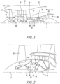
- the core airflow A is accelerated and compressed by the low pressure compressor 14 and directed into the high pressure compressor 15 where further compression takes place.
- the compressed air exhausted from the high pressure compressor 15 is directed into the combustion equipment 16 where it is mixed with fuel and the mixture is combusted.
- the resultant hot combustion products then expand through, and thereby drive, the high pressure and low pressure turbines 17, 19 before being exhausted through the nozzle 20 to provide some propulsive thrust.
- the high pressure turbine 17 drives the high pressure compressor 15 by a suitable interconnecting shaft 27.
- the fan 23 generally provides the majority of the propulsive thrust.
- the epicyclic gearbox 30 is a reduction gearbox.
- FIG. 2 An exemplary arrangement for a geared fan gas turbine engine 10 is shown in Figure 2 .
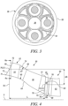
- the low pressure turbine 19 (see Figure 1 ) drives the shaft 26, which is coupled to a sun wheel, or sun gear, 28 of the epicyclic gear arrangement 30.
- a sun wheel, or sun gear, 28 of the epicyclic gear arrangement 30 Radially outwardly of the sun gear 28 and intermeshing therewith is a plurality of planet gears 32 that are coupled together by a planet carrier 34.
- the planet carrier 34 constrains the planet gears 32 to process around the sun gear 28 in synchronicity whilst enabling each planet gear 32 to rotate about its own axis.
- the planet carrier 34 is coupled via linkages 36 to the fan 23 in order to drive its rotation about the engine axis 9.
- an annulus or ring gear 38 Radially outwardly of the planet gears 32 and intermeshing therewith is an annulus or ring gear 38 that is coupled, via linkages 40, to a stationary supporting structure 24.
- low pressure turbine and “low pressure compressor” as used herein may be taken to mean the lowest pressure turbine stages and lowest pressure compressor stages (i.e. not including the fan 23) respectively and/or the turbine and compressor stages that are connected together by the interconnecting shaft 26 with the lowest rotational speed in the engine (i.e. not including the gearbox output shaft that drives the fan 23).
- the "low pressure turbine” and “low pressure compressor” referred to herein may alternatively be known as the "intermediate pressure turbine” and “intermediate pressure compressor”. Where such alternative nomenclature is used, the fan 23 may be referred to as a first, or lowest pressure, compression stage.
- the epicyclic gearbox 30 is shown by way of example in greater detail in Figure 3 .
- Each of the sun gear 28, planet gears 32 and ring gear 38 comprise teeth about their periphery to intermesh with the other gears. However, for clarity only exemplary portions of the teeth are illustrated in Figure 3 .
- Practical applications of a planetary epicyclic gearbox 30 generally comprise at least three planet gears 32.
- any suitable arrangement may be used for locating the gearbox 30 in the engine 10 and/or for connecting the gearbox 30 to the engine 10.
- the connections (such as the linkages 36, 40 in the Figure 2 example) between the gearbox 30 and other parts of the engine 10 (such as the input shaft 26, the output shaft and the fixed structure 24) may have any desired degree of stiffness or flexibility.
- the gearbox may drive additional and/or alternative components (e.g. the intermediate pressure compressor and/or a booster compressor).
- additional and/or alternative components e.g. the intermediate pressure compressor and/or a booster compressor.
- the ESS vanes 54 are uniformly spaced circumferentially around the engine main axis 9 and have an aerofoil profile with an ESS leading edge 72 and an ESS trailing edge 74.
- the aerofoil profile extends in a chordwise direction from the leading edge to the trailing edge and in a spanwise direction from a first, radially inward end to a second, radially outward end.
- the ESS leading edge 72 extends from a first, radially inward, point 71 corresponding to 0% span to a second, radially outward, point 73 corresponding to 100 % span.
- Point 71 may be referred to as 0% span ESS leading edge point 71 and point 73 as 100% span ESS leading edge point 73.
- a mid-span ESS leading edge point PLE1 is defined on the ESS leading edge 72 at 50% span, midway between the inner wall 64 and the outer wall 66, or in other words midway between the 0% span ESS leading edge point 71 and the 100% span ESS leading edge point 73.
- the mid-span ESS leading edge point PLE1 is arranged at a first radius R1 from the engine main axis 9.
- the VIGVs 58 are uniformly arranged circumferentially about the engine main axis 9 immediately upstream of the first rotor 60 of the low pressure compressor 14.
- the VIGVs 58 are rotatable about respective radial, or nearly radial, pivot axes 80, for example by means of a rotation mechanism per se known and therefore not illustrated in detail.
- each individual vane in a VIGV row is typically supported in two journal bearings at the radially inner and outer ends of the vane aerofoil section.
- the journal bearings permit the vane aerofoil to rotate or pivot about its spanwise axis. This axis is typically radial, or nearly radial, relative to the compressor or engine main axis 9.
- the VIGVs 58 have an VIGV leading edge 76 and a VIGV trailing edge 78 and extend in a chordwise direction from the VIGV leading edge 76 to the VIGV trailing edge 78 and in a spanwise direction from a first, radially inward, end to a second, radially outward, end.
- the VIGV leading edge 76 extends from a first, radially inward point 75 corresponding to 0% span to a second, radially outward point 77 corresponding to 100 % span.
- Point 75 may be referred to as 0% span VIGV leading edge point 75 and point 77 as 100% span VIGV leading edge point 77.
- a mid-span VIGV leading edge point PLE2 is defined on the VIGV leading edge 76 at 50% span, midway between the inner wall 64 and the outer wall 66, or in other words midway between the 0% span VIGV leading edge point 75 and 100% span VIGV leading edge point 77.
- the mid-span VIGV leading edge point PLE2 is arranged at a second radius R2 from the engine main axis 9.
- the first radius R1 is generally greater than the second radius R2 and the difference ⁇ R between R1 and R2 is comprised between 60 mm and 280 mm, preferably between 150 mm and 260 mm. In an embodiment, the difference ⁇ R between R1 and R2 is for example 200 mm.
- the mid-span ESS leading edge point PLE1 is axially distanced from the mid-span VIGV leading edge point PLE2 by an axial distance L.
- the axial distance L is comprised between 300 mm and 650 mm, preferably between 450 mm and 650 mm. In an embodiment, the axial distance L is for example 500 mm.
- the ratio ⁇ R/L of the difference ⁇ R between the first radius R1 and the second radius R2 to the axial distance L is comprised between 0.23 and 0.70, preferably between 0.40 and 0.70. In an embodiment, the ratio ⁇ R/L is for example equal to 0.45.
- the VIGVs 58 are arranged angularly rotated about the engine main axes 9 by a rotation angle ⁇ with respect to the ESS vanes 54, so that the VIGVs 58 are positioned in a shielded position with respect to the ESS vanes 54 to reduce water droplets contacting the VIGVs and therefore ice buildup.
- the VIGVs 58 are positioned such that a radially outer part of the VIGVs 58 is shielded.
- the radially outer part may be defined as the part of the VIGVs 58 between 40 and 100% span height.
- Figure 5 is a schematic, simplified front view of the inlet duct 50 taken along arrows 6a-6a and 6b-6b of figure 4 to show ESS vanes 54 and corresponding VIGVs 58.
- figure 5 shows a first cross-section 6a-6a taken at a first transversal plane passing through points 90 defined at 70% span on the ESS leading edge 72 and a second cross-section 6b-6b taken at a second transversal plane passing through points 92 defined at 70% span on the pivot axes 80.
- Points 90 may be referred to as 70% span ESS leading edge points 90 and points 92 as 70% span VIGV pivot axis points 92.
- Figure 5 further illustrates first longitudinal planes LP1 passing through respective 70% span ESS leading edge points 90 and second longitudinal planes LP2 passing through respective 70% span VIGV pivot axis points 92.
- the first longitudinal plane LP1 and second longitudinal plane LP2 pass through the engine main axis 9.
- the corresponding second longitudinal plane LP2 is defined as the adjacent second longitudinal plane LP2 in a clockwise direction as seen from the front of the engine, namely as shown in figure 5 .
- a corresponding VIGV 58 is defined as the adjacent VIGV 58 in a clockwise direction as seen from the front of the engine.
- the ESS vanes 54 and VIGVs 58 are in a same number comprised between 40 and 80, for example 48, or 54, or 60, and, as both the ESS vanes 54 and VIGVs 58 are uniformly angularly arranged about the engine main axis 9, for each pair of ESS vane 58 and corresponding VIGV 58 the rotation angle ⁇ is the same.
- the VIGVs 58 are rotatable about the respective pivot axes 80 and therefore the VIGV leading edge 76 moves with respect to the ESS leading edge 72, whereas the pivot axis 80 does not. Consequently, the mutual position of the ESS leading edge 72 and the pivot axis 80, for any span height, does not change, even if the VIGV rotates.
- the rotation angle ⁇ between the first longitudinal plane LP1 and the second longitudinal plane LP2 does not depend on the VIGV rotation and does not vary with the VIGV rotation about the pivot axis 80.
- the rotation angle between corresponding longitudinal planes passing through points at different span heights i.e.
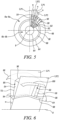
- Figure 6 further shows the first longitudinal plane LP1 passing through the 70% span ESS leading edge point 90 of the ESS vane 54 and the second longitudinal plane LP2 passing through the 70% span VIGV pivot axis point 92 of the VIGV 58.
- the second longitudinal plane LP2 is rotated by the rotation angle ⁇ from the first longitudinal plane LP1 about the engine main axis 9 in a clockwise direction when seen from the front of the engine.
- the rotation angle ⁇ is comprised between 0.1° and 6°, for example 2°, or 2.5°, or 3°.
- the first longitudinal plane LP1 intersects the inner wall 64 along a first line 94 and the outer wall 66 along a second line 96. Both first and second lines 94, 96 are shown as dotted lines in figure 6 .
- the second longitudinal plane LP2 intersects the inner wall 64 along a third line 98 and the outer wall 66 along a fourth line 100. Both the third and fourth lines 98, 100 are shown as dotted lines in figure 6 .
Landscapes
- Engineering & Computer Science (AREA)
- Mechanical Engineering (AREA)
- General Engineering & Computer Science (AREA)
- Chemical & Material Sciences (AREA)
- Combustion & Propulsion (AREA)
- Physics & Mathematics (AREA)
- Geometry (AREA)
- Fluid Mechanics (AREA)
- Structures Of Non-Positive Displacement Pumps (AREA)
Claims (11)
- Gasturbinentriebwerk (10), umfassend:- einen Lüfter (23), der sich um eine Motorhauptachse (9) dreht und einen Kernluftstrom (A) und einen Umgehungsluftstrom (B) erzeugt;- einen Kernkanal (50), über den der Kernluftstrom (A) strömt;- einen Triebwerkskern (11), der Folgendes umfasst:- einen Verdichter (14) zum Verdichten des Kernluftstroms (A), der eine Vielzahl von Stufen umfasst, wobei jede Stufe eine Reihe von Rotorschaufeln und eine Reihe von Statorschaufeln umfasst, wobei eine erste Stufe der Vielzahl von Stufen an einem Einlass des Verdichters angeordnet ist;- eine Verbrennungsausrüstung (16); und- eine Turbine (19), die über eine Welle (26) mit dem Verdichter verbunden ist;- einen Motorabschnittsstator (ESS) (52), der eine Vielzahl von ESS-Schaufeln (54) umfasst und in dem Kernkanal stromabwärts des Lüfters angeordnet ist, wobei jede ESS-Schaufel eine ESS-Vorderkante (72) und eine ESS-Hinterkante (74) umfasst; und- eine Vielzahl von verstellbaren Eintrittsleitschaufeln (VIGV) (58), die dazu angepasst sind, sich um eine Schwenkachse (80) zu drehen, und in dem Kernkanal stromabwärts des ESS und stromaufwärts des Verdichters angeordnet sind, wobei jede verstellbare Eintrittsleitschaufel (VIGV) eine VIGV-Vorderkante (76) und eine VIGV-Hinterkante (78) umfasst,wobei ein ESS-Vorderkantenpunkt (PLE1) in der Mitte der Spannweite in einem ersten Radius R1 von der Triebwerkshauptachse angeordnet ist und ein VIGV-Vorderkantenpunkt (PLE2) in der Mitte der Spannweite in einem zweiten Radius R2 von der Triebwerkshauptachse angeordnet ist, wobei sich der ESS-Vorderkantenpunkt (PLE1) in der Mitte der Spannweite in einer axialen Entfernung L von dem VIGV-Vorderkantenpunkt (PLE2) in der Mitte der Spannweite befindet,dadurch gekennzeichnet, dass das Verhältnis ΔR/L einer Differenz ΔR zwischen dem ersten Radius R1 und dem zweiten Radius R2 zu der axialen Entfernung L zwischen 0,23 und 0,70, vorzugsweise zwischen 0,40 und 0,70, liegt unddadurch, dass die VIGV-Schaufeln in Bezug auf die ESS-Schaufeln derart winkelverdreht angeordnet sind, dass sich erste Längsebenen (LP1), die durch die Triebwerkshauptachse verlaufen, radial davon erstrecken und in Bezug auf entsprechende zweite Längsebenen (LP2), die durch die Triebwerkshauptachse verlaufen, die sich radial davon erstrecken, jeweils durch ESS-Vorderkantenpunkte (90) bei 70 % der Spannweite und durch entsprechende VIGV-Schwenkachsenpunkte (92) bei 70 % der Spannweite um einen Drehwinkel α, der zwischen 0,1° und 6° umfasst ist, gedreht werden.
- Gasturbinentriebwerk nach Anspruch 1, wobei die Schwenkachse (80) im Wesentlichen radial ist.
- Gasturbinentriebwerk nach einem der vorhergehenden Ansprüche, wobei der ESS (52) 40 bis 80 ESS-Schaufeln (54), vorzugsweise 40 bis 60, umfasst.
- Gasturbinentriebwerk nach einem der vorhergehenden Ansprüche, wobei die Anzahl der VIGVs (58) zwischen 40 und 80, vorzugsweise zwischen 40 und 60, liegt.
- Gasturbinentriebwerk nach einem der vorhergehenden Ansprüche, ferner umfassend eine Strebe (56), die in dem Kernkanal (50) zwischen dem ESS (52) und den VIGVs (58) angeordnet ist.
- Gasturbinentriebwerk nach einem der vorhergehenden Ansprüche, wobei der Verdichter (14) ein erster Verdichter ist, die Turbine (19) eine erste Turbine ist und die Welle (26) eine erste Welle ist, wobei der Triebwerkskern (11) ferner einen zweiten Verdichter (15) stromabwärts des ersten Verdichters, eine zweite Turbine (17) stromaufwärts der ersten Turbine und eine zweite Welle (27) umfasst, welche die zweite Turbine mit dem zweiten Verdichter verbindet.
- Gasturbinentriebwerk nach einem der vorhergehenden Ansprüche, ferner umfassend ein Untersetzungsgetriebe (30), das eine Eingabe von der Welle (26) empfängt und Antrieb an den Lüfter (23) ausgibt, um den Lüfter (23) bei einer niedrigeren Drehzahl als die Welle (26) anzutreiben.
- Gasturbinentriebwerk nach dem vorhergehenden Anspruch, wobei das Getriebe (30) ein Untersetzungsverhältnis aufweist, das zwischen 3,1 und 3,8, vorzugsweise zwischen 3,1 und 3,7, noch bevorzugter zwischen 3,2 und 3,6, umfasst ist.
- Gasturbinentriebwerk nach einem der vorhergehenden Ansprüche, wobei der Lüfter (23) einen Durchmesser aufweist, der zwischen 240 cm und 400 cm, vorzugsweise zwischen 300 cm und 390 cm, noch bevorzugter zwischen 330 cm und 380 cm, sogar noch bevorzugter zwischen 335 cm und 360 cm, liegt.
- Gasturbinentriebwerk nach einem der vorhergehenden Ansprüche, wobei die axiale Entfernung L zwischen 80 mm und 650 mm, vorzugsweise zwischen 150 mm und 550 mm, liegt.
- Gasturbinentriebwerk nach einem der vorhergehenden Ansprüche, wobei die Differenz ΔR zwischen 60 mm und 280 mm, vorzugsweise zwischen 75 mm und 260 mm, umfasst ist.
Applications Claiming Priority (1)
| Application Number | Priority Date | Filing Date | Title |
|---|---|---|---|
| GBGB2018264.8A GB202018264D0 (en) | 2020-11-20 | 2020-11-20 | Gas turbine engine with improved vigv shielding |
Publications (2)
| Publication Number | Publication Date |
|---|---|
| EP4001595A1 EP4001595A1 (de) | 2022-05-25 |
| EP4001595B1 true EP4001595B1 (de) | 2023-12-13 |
Family
ID=74046837
Family Applications (1)
| Application Number | Title | Priority Date | Filing Date |
|---|---|---|---|
| EP21203636.2A Active EP4001595B1 (de) | 2020-11-20 | 2021-10-20 | Gasturbinentriebwerk mit verbesserter verstellbarer eintrittsleitschaufel abschirmung |
Country Status (4)
| Country | Link |
|---|---|
| US (2) | US11634993B2 (de) |
| EP (1) | EP4001595B1 (de) |
| CN (1) | CN114517712A (de) |
| GB (1) | GB202018264D0 (de) |
Families Citing this family (3)
| Publication number | Priority date | Publication date | Assignee | Title |
|---|---|---|---|---|
| US12017782B2 (en) | 2022-05-30 | 2024-06-25 | Pratt & Whitney Canada Corp. | Aircraft engine with stator having varying pitch |
| US11939886B2 (en) | 2022-05-30 | 2024-03-26 | Pratt & Whitney Canada Corp. | Aircraft engine having stator vanes made of different materials |
| US12091178B2 (en) * | 2022-05-30 | 2024-09-17 | Pratt & Whitney Canada Corp. | Aircraft engine with stator having varying geometry |
Family Cites Families (4)
| Publication number | Priority date | Publication date | Assignee | Title |
|---|---|---|---|---|
| US20100172747A1 (en) * | 2009-01-08 | 2010-07-08 | General Electric Company | Plasma enhanced compressor duct |
| FR3027053B1 (fr) * | 2014-10-10 | 2019-09-13 | Safran Aircraft Engines | Stator de turbomachine d'aeronef |
| GB201616108D0 (en) * | 2016-09-22 | 2016-11-09 | Rolls Royce Plc | Gas turbine engine |
| GB201900733D0 (en) * | 2019-01-18 | 2019-03-06 | Rolls Royce Plc | Highly loaded inlet duct in a geared turbofan |
-
2020
- 2020-11-20 GB GBGB2018264.8A patent/GB202018264D0/en not_active Ceased
-
2021
- 2021-10-20 EP EP21203636.2A patent/EP4001595B1/de active Active
- 2021-10-29 US US17/514,977 patent/US11634993B2/en active Active
- 2021-11-19 CN CN202111376525.1A patent/CN114517712A/zh active Pending
-
2023
- 2023-03-17 US US18/122,807 patent/US11920499B2/en active Active
Also Published As
| Publication number | Publication date |
|---|---|
| EP4001595A1 (de) | 2022-05-25 |
| CN114517712A (zh) | 2022-05-20 |
| GB202018264D0 (en) | 2021-01-06 |
| US11634993B2 (en) | 2023-04-25 |
| US20220162953A1 (en) | 2022-05-26 |
| US20230220780A1 (en) | 2023-07-13 |
| US11920499B2 (en) | 2024-03-05 |
Similar Documents
| Publication | Publication Date | Title |
|---|---|---|
| US10844721B2 (en) | Gas turbine engine for an aircraft | |
| EP3591168A1 (de) | Lüfterentwurf | |
| EP3587749B1 (de) | Gasturbinentriebwerk | |
| US11920499B2 (en) | Gas turbine engine with improved VIGV shielding | |
| US12286895B2 (en) | Super-cooled ice impact protection for a gas turbine engine | |
| EP3913192B1 (de) | Gasturbinenmotor | |
| EP3608509B1 (de) | Gasturbinentriebwerk mit turbinenkomponenten aus keramikmatrixverbundstoff | |
| US11732603B2 (en) | Ice crystal protection for a gas turbine engine | |
| EP3564518A1 (de) | Mit einem gitter versehene entnahmevorrichtung | |
| EP3683431A1 (de) | Hochbelasteter einlasskanal in einem getriebeturbofan | |
| EP3647576A1 (de) | Gasturbinentriebwerk | |
| EP3708850B1 (de) | Kernstromkanalanordnung für ein turbotriebwerk | |
| EP3594476A1 (de) | Befestigungsanordnung für einen getriebefan eines gasturbinentriebwerks | |
| US12442308B2 (en) | Gas turbine engine with relative clocking of bifurcations |
Legal Events
| Date | Code | Title | Description |
|---|---|---|---|
| PUAI | Public reference made under article 153(3) epc to a published international application that has entered the european phase |
Free format text: ORIGINAL CODE: 0009012 |
|
| STAA | Information on the status of an ep patent application or granted ep patent |
Free format text: STATUS: THE APPLICATION HAS BEEN PUBLISHED |
|
| AK | Designated contracting states |
Kind code of ref document: A1 Designated state(s): AL AT BE BG CH CY CZ DE DK EE ES FI FR GB GR HR HU IE IS IT LI LT LU LV MC MK MT NL NO PL PT RO RS SE SI SK SM TR |
|
| STAA | Information on the status of an ep patent application or granted ep patent |
Free format text: STATUS: REQUEST FOR EXAMINATION WAS MADE |
|
| 17P | Request for examination filed |
Effective date: 20221020 |
|
| RBV | Designated contracting states (corrected) |
Designated state(s): AL AT BE BG CH CY CZ DE DK EE ES FI FR GB GR HR HU IE IS IT LI LT LU LV MC MK MT NL NO PL PT RO RS SE SI SK SM TR |
|
| GRAP | Despatch of communication of intention to grant a patent |
Free format text: ORIGINAL CODE: EPIDOSNIGR1 |
|
| STAA | Information on the status of an ep patent application or granted ep patent |
Free format text: STATUS: GRANT OF PATENT IS INTENDED |
|
| RIC1 | Information provided on ipc code assigned before grant |
Ipc: F02C 7/042 20060101ALI20230922BHEP Ipc: F01D 5/14 20060101ALI20230922BHEP Ipc: F01D 9/04 20060101ALI20230922BHEP Ipc: F01D 25/02 20060101ALI20230922BHEP Ipc: F02K 3/06 20060101ALI20230922BHEP Ipc: F04D 29/56 20060101ALI20230922BHEP Ipc: F01D 17/16 20060101AFI20230922BHEP |
|
| GRAS | Grant fee paid |
Free format text: ORIGINAL CODE: EPIDOSNIGR3 |
|
| GRAA | (expected) grant |
Free format text: ORIGINAL CODE: 0009210 |
|
| STAA | Information on the status of an ep patent application or granted ep patent |
Free format text: STATUS: THE PATENT HAS BEEN GRANTED |
|
| INTG | Intention to grant announced |
Effective date: 20231024 |
|
| AK | Designated contracting states |
Kind code of ref document: B1 Designated state(s): AL AT BE BG CH CY CZ DE DK EE ES FI FR GB GR HR HU IE IS IT LI LT LU LV MC MK MT NL NO PL PT RO RS SE SI SK SM TR |
|
| P01 | Opt-out of the competence of the unified patent court (upc) registered |
Effective date: 20231102 |
|
| REG | Reference to a national code |
Ref country code: GB Ref legal event code: FG4D |
|
| REG | Reference to a national code |
Ref country code: CH Ref legal event code: EP |
|
| REG | Reference to a national code |
Ref country code: DE Ref legal event code: R096 Ref document number: 602021007652 Country of ref document: DE |
|
| REG | Reference to a national code |
Ref country code: IE Ref legal event code: FG4D |
|
| PG25 | Lapsed in a contracting state [announced via postgrant information from national office to epo] |
Ref country code: GR Free format text: LAPSE BECAUSE OF FAILURE TO SUBMIT A TRANSLATION OF THE DESCRIPTION OR TO PAY THE FEE WITHIN THE PRESCRIBED TIME-LIMIT Effective date: 20240314 |
|
| REG | Reference to a national code |
Ref country code: LT Ref legal event code: MG9D |
|
| PG25 | Lapsed in a contracting state [announced via postgrant information from national office to epo] |
Ref country code: LT Free format text: LAPSE BECAUSE OF FAILURE TO SUBMIT A TRANSLATION OF THE DESCRIPTION OR TO PAY THE FEE WITHIN THE PRESCRIBED TIME-LIMIT Effective date: 20231213 |
|
| REG | Reference to a national code |
Ref country code: NL Ref legal event code: MP Effective date: 20231213 |
|
| PG25 | Lapsed in a contracting state [announced via postgrant information from national office to epo] |
Ref country code: ES Free format text: LAPSE BECAUSE OF FAILURE TO SUBMIT A TRANSLATION OF THE DESCRIPTION OR TO PAY THE FEE WITHIN THE PRESCRIBED TIME-LIMIT Effective date: 20231213 |
|
| PG25 | Lapsed in a contracting state [announced via postgrant information from national office to epo] |
Ref country code: LT Free format text: LAPSE BECAUSE OF FAILURE TO SUBMIT A TRANSLATION OF THE DESCRIPTION OR TO PAY THE FEE WITHIN THE PRESCRIBED TIME-LIMIT Effective date: 20231213 Ref country code: GR Free format text: LAPSE BECAUSE OF FAILURE TO SUBMIT A TRANSLATION OF THE DESCRIPTION OR TO PAY THE FEE WITHIN THE PRESCRIBED TIME-LIMIT Effective date: 20240314 Ref country code: ES Free format text: LAPSE BECAUSE OF FAILURE TO SUBMIT A TRANSLATION OF THE DESCRIPTION OR TO PAY THE FEE WITHIN THE PRESCRIBED TIME-LIMIT Effective date: 20231213 Ref country code: BG Free format text: LAPSE BECAUSE OF FAILURE TO SUBMIT A TRANSLATION OF THE DESCRIPTION OR TO PAY THE FEE WITHIN THE PRESCRIBED TIME-LIMIT Effective date: 20240313 |
|
| REG | Reference to a national code |
Ref country code: AT Ref legal event code: MK05 Ref document number: 1640607 Country of ref document: AT Kind code of ref document: T Effective date: 20231213 |
|
| PG25 | Lapsed in a contracting state [announced via postgrant information from national office to epo] |
Ref country code: NL Free format text: LAPSE BECAUSE OF FAILURE TO SUBMIT A TRANSLATION OF THE DESCRIPTION OR TO PAY THE FEE WITHIN THE PRESCRIBED TIME-LIMIT Effective date: 20231213 |
|
| PG25 | Lapsed in a contracting state [announced via postgrant information from national office to epo] |
Ref country code: SE Free format text: LAPSE BECAUSE OF FAILURE TO SUBMIT A TRANSLATION OF THE DESCRIPTION OR TO PAY THE FEE WITHIN THE PRESCRIBED TIME-LIMIT Effective date: 20231213 Ref country code: RS Free format text: LAPSE BECAUSE OF FAILURE TO SUBMIT A TRANSLATION OF THE DESCRIPTION OR TO PAY THE FEE WITHIN THE PRESCRIBED TIME-LIMIT Effective date: 20231213 Ref country code: NO Free format text: LAPSE BECAUSE OF FAILURE TO SUBMIT A TRANSLATION OF THE DESCRIPTION OR TO PAY THE FEE WITHIN THE PRESCRIBED TIME-LIMIT Effective date: 20240313 Ref country code: NL Free format text: LAPSE BECAUSE OF FAILURE TO SUBMIT A TRANSLATION OF THE DESCRIPTION OR TO PAY THE FEE WITHIN THE PRESCRIBED TIME-LIMIT Effective date: 20231213 Ref country code: LV Free format text: LAPSE BECAUSE OF FAILURE TO SUBMIT A TRANSLATION OF THE DESCRIPTION OR TO PAY THE FEE WITHIN THE PRESCRIBED TIME-LIMIT Effective date: 20231213 Ref country code: HR Free format text: LAPSE BECAUSE OF FAILURE TO SUBMIT A TRANSLATION OF THE DESCRIPTION OR TO PAY THE FEE WITHIN THE PRESCRIBED TIME-LIMIT Effective date: 20231213 |
|
| PG25 | Lapsed in a contracting state [announced via postgrant information from national office to epo] |
Ref country code: IS Free format text: LAPSE BECAUSE OF FAILURE TO SUBMIT A TRANSLATION OF THE DESCRIPTION OR TO PAY THE FEE WITHIN THE PRESCRIBED TIME-LIMIT Effective date: 20240413 |
|
| PG25 | Lapsed in a contracting state [announced via postgrant information from national office to epo] |
Ref country code: AT Free format text: LAPSE BECAUSE OF FAILURE TO SUBMIT A TRANSLATION OF THE DESCRIPTION OR TO PAY THE FEE WITHIN THE PRESCRIBED TIME-LIMIT Effective date: 20231213 Ref country code: CZ Free format text: LAPSE BECAUSE OF FAILURE TO SUBMIT A TRANSLATION OF THE DESCRIPTION OR TO PAY THE FEE WITHIN THE PRESCRIBED TIME-LIMIT Effective date: 20231213 |
|
| PG25 | Lapsed in a contracting state [announced via postgrant information from national office to epo] |
Ref country code: SK Free format text: LAPSE BECAUSE OF FAILURE TO SUBMIT A TRANSLATION OF THE DESCRIPTION OR TO PAY THE FEE WITHIN THE PRESCRIBED TIME-LIMIT Effective date: 20231213 |
|
| PG25 | Lapsed in a contracting state [announced via postgrant information from national office to epo] |
Ref country code: SM Free format text: LAPSE BECAUSE OF FAILURE TO SUBMIT A TRANSLATION OF THE DESCRIPTION OR TO PAY THE FEE WITHIN THE PRESCRIBED TIME-LIMIT Effective date: 20231213 Ref country code: SK Free format text: LAPSE BECAUSE OF FAILURE TO SUBMIT A TRANSLATION OF THE DESCRIPTION OR TO PAY THE FEE WITHIN THE PRESCRIBED TIME-LIMIT Effective date: 20231213 Ref country code: RO Free format text: LAPSE BECAUSE OF FAILURE TO SUBMIT A TRANSLATION OF THE DESCRIPTION OR TO PAY THE FEE WITHIN THE PRESCRIBED TIME-LIMIT Effective date: 20231213 Ref country code: IT Free format text: LAPSE BECAUSE OF FAILURE TO SUBMIT A TRANSLATION OF THE DESCRIPTION OR TO PAY THE FEE WITHIN THE PRESCRIBED TIME-LIMIT Effective date: 20231213 Ref country code: IS Free format text: LAPSE BECAUSE OF FAILURE TO SUBMIT A TRANSLATION OF THE DESCRIPTION OR TO PAY THE FEE WITHIN THE PRESCRIBED TIME-LIMIT Effective date: 20240413 Ref country code: EE Free format text: LAPSE BECAUSE OF FAILURE TO SUBMIT A TRANSLATION OF THE DESCRIPTION OR TO PAY THE FEE WITHIN THE PRESCRIBED TIME-LIMIT Effective date: 20231213 Ref country code: CZ Free format text: LAPSE BECAUSE OF FAILURE TO SUBMIT A TRANSLATION OF THE DESCRIPTION OR TO PAY THE FEE WITHIN THE PRESCRIBED TIME-LIMIT Effective date: 20231213 Ref country code: AT Free format text: LAPSE BECAUSE OF FAILURE TO SUBMIT A TRANSLATION OF THE DESCRIPTION OR TO PAY THE FEE WITHIN THE PRESCRIBED TIME-LIMIT Effective date: 20231213 |
|
| PG25 | Lapsed in a contracting state [announced via postgrant information from national office to epo] |
Ref country code: PT Free format text: LAPSE BECAUSE OF FAILURE TO SUBMIT A TRANSLATION OF THE DESCRIPTION OR TO PAY THE FEE WITHIN THE PRESCRIBED TIME-LIMIT Effective date: 20240415 Ref country code: PL Free format text: LAPSE BECAUSE OF FAILURE TO SUBMIT A TRANSLATION OF THE DESCRIPTION OR TO PAY THE FEE WITHIN THE PRESCRIBED TIME-LIMIT Effective date: 20231213 |
|
| REG | Reference to a national code |
Ref country code: DE Ref legal event code: R097 Ref document number: 602021007652 Country of ref document: DE |
|
| PG25 | Lapsed in a contracting state [announced via postgrant information from national office to epo] |
Ref country code: DK Free format text: LAPSE BECAUSE OF FAILURE TO SUBMIT A TRANSLATION OF THE DESCRIPTION OR TO PAY THE FEE WITHIN THE PRESCRIBED TIME-LIMIT Effective date: 20231213 |
|
| PLBE | No opposition filed within time limit |
Free format text: ORIGINAL CODE: 0009261 |
|
| STAA | Information on the status of an ep patent application or granted ep patent |
Free format text: STATUS: NO OPPOSITION FILED WITHIN TIME LIMIT |
|
| PG25 | Lapsed in a contracting state [announced via postgrant information from national office to epo] |
Ref country code: SI Free format text: LAPSE BECAUSE OF FAILURE TO SUBMIT A TRANSLATION OF THE DESCRIPTION OR TO PAY THE FEE WITHIN THE PRESCRIBED TIME-LIMIT Effective date: 20231213 |
|
| PG25 | Lapsed in a contracting state [announced via postgrant information from national office to epo] |
Ref country code: SI Free format text: LAPSE BECAUSE OF FAILURE TO SUBMIT A TRANSLATION OF THE DESCRIPTION OR TO PAY THE FEE WITHIN THE PRESCRIBED TIME-LIMIT Effective date: 20231213 Ref country code: DK Free format text: LAPSE BECAUSE OF FAILURE TO SUBMIT A TRANSLATION OF THE DESCRIPTION OR TO PAY THE FEE WITHIN THE PRESCRIBED TIME-LIMIT Effective date: 20231213 |
|
| 26N | No opposition filed |
Effective date: 20240916 |
|
| REG | Reference to a national code |
Ref country code: CH Ref legal event code: PL |
|
| PG25 | Lapsed in a contracting state [announced via postgrant information from national office to epo] |
Ref country code: MC Free format text: LAPSE BECAUSE OF FAILURE TO SUBMIT A TRANSLATION OF THE DESCRIPTION OR TO PAY THE FEE WITHIN THE PRESCRIBED TIME-LIMIT Effective date: 20231213 |
|
| PG25 | Lapsed in a contracting state [announced via postgrant information from national office to epo] |
Ref country code: LU Free format text: LAPSE BECAUSE OF NON-PAYMENT OF DUE FEES Effective date: 20241020 Ref country code: BE Free format text: LAPSE BECAUSE OF NON-PAYMENT OF DUE FEES Effective date: 20241031 |
|
| PG25 | Lapsed in a contracting state [announced via postgrant information from national office to epo] |
Ref country code: CH Free format text: LAPSE BECAUSE OF NON-PAYMENT OF DUE FEES Effective date: 20241031 |
|
| REG | Reference to a national code |
Ref country code: BE Ref legal event code: MM Effective date: 20241031 |
|
| PG25 | Lapsed in a contracting state [announced via postgrant information from national office to epo] |
Ref country code: FI Free format text: LAPSE BECAUSE OF FAILURE TO SUBMIT A TRANSLATION OF THE DESCRIPTION OR TO PAY THE FEE WITHIN THE PRESCRIBED TIME-LIMIT Effective date: 20231213 |
|
| PG25 | Lapsed in a contracting state [announced via postgrant information from national office to epo] |
Ref country code: IE Free format text: LAPSE BECAUSE OF NON-PAYMENT OF DUE FEES Effective date: 20241020 |
|
| PGFP | Annual fee paid to national office [announced via postgrant information from national office to epo] |
Ref country code: DE Payment date: 20251028 Year of fee payment: 5 |
|
| PGFP | Annual fee paid to national office [announced via postgrant information from national office to epo] |
Ref country code: GB Payment date: 20251023 Year of fee payment: 5 |
|
| PGFP | Annual fee paid to national office [announced via postgrant information from national office to epo] |
Ref country code: FR Payment date: 20251027 Year of fee payment: 5 |
|
| PG25 | Lapsed in a contracting state [announced via postgrant information from national office to epo] |
Ref country code: CY Free format text: LAPSE BECAUSE OF FAILURE TO SUBMIT A TRANSLATION OF THE DESCRIPTION OR TO PAY THE FEE WITHIN THE PRESCRIBED TIME-LIMIT; INVALID AB INITIO Effective date: 20211020 |
|
| PG25 | Lapsed in a contracting state [announced via postgrant information from national office to epo] |
Ref country code: HU Free format text: LAPSE BECAUSE OF FAILURE TO SUBMIT A TRANSLATION OF THE DESCRIPTION OR TO PAY THE FEE WITHIN THE PRESCRIBED TIME-LIMIT; INVALID AB INITIO Effective date: 20211020 |