EP4001592A1 - Cmc vane arc segment with cantilevered spar - Google Patents
Cmc vane arc segment with cantilevered spar Download PDFInfo
- Publication number
- EP4001592A1 EP4001592A1 EP21205653.5A EP21205653A EP4001592A1 EP 4001592 A1 EP4001592 A1 EP 4001592A1 EP 21205653 A EP21205653 A EP 21205653A EP 4001592 A1 EP4001592 A1 EP 4001592A1
- Authority
- EP
- European Patent Office
- Prior art keywords
- hollow
- arc segment
- spar
- leg
- recited
- Prior art date
- Legal status (The legal status is an assumption and is not a legal conclusion. Google has not performed a legal analysis and makes no representation as to the accuracy of the status listed.)
- Pending
Links
- 239000000919 ceramic Substances 0.000 claims abstract description 48
- 238000004891 communication Methods 0.000 claims description 5
- 239000013078 crystal Substances 0.000 claims description 4
- 239000012530 fluid Substances 0.000 claims description 4
- 229910045601 alloy Inorganic materials 0.000 claims description 3
- 239000000956 alloy Substances 0.000 claims description 3
- 239000007789 gas Substances 0.000 description 12
- 239000011153 ceramic matrix composite Substances 0.000 description 10
- 239000000835 fiber Substances 0.000 description 5
- 239000000446 fuel Substances 0.000 description 5
- 230000008901 benefit Effects 0.000 description 4
- 229920002134 Carboxymethyl cellulose Polymers 0.000 description 3
- 235000010948 carboxy methyl cellulose Nutrition 0.000 description 3
- 229920006184 cellulose methylcellulose Polymers 0.000 description 3
- 238000012710 chemistry, manufacturing and control Methods 0.000 description 3
- 239000000463 material Substances 0.000 description 3
- 230000009467 reduction Effects 0.000 description 3
- 238000005452 bending Methods 0.000 description 2
- 239000011159 matrix material Substances 0.000 description 2
- 230000003068 static effect Effects 0.000 description 2
- 230000035882 stress Effects 0.000 description 2
- 229910000601 superalloy Inorganic materials 0.000 description 2
- 230000008646 thermal stress Effects 0.000 description 2
- 229910000990 Ni alloy Inorganic materials 0.000 description 1
- 238000005266 casting Methods 0.000 description 1
- 229910010293 ceramic material Inorganic materials 0.000 description 1
- 230000008859 change Effects 0.000 description 1
- 239000000567 combustion gas Substances 0.000 description 1
- 238000002485 combustion reaction Methods 0.000 description 1
- 230000006835 compression Effects 0.000 description 1
- 238000007906 compression Methods 0.000 description 1
- 238000005094 computer simulation Methods 0.000 description 1
- 239000012141 concentrate Substances 0.000 description 1
- 238000001816 cooling Methods 0.000 description 1
- 238000003754 machining Methods 0.000 description 1
- 230000007246 mechanism Effects 0.000 description 1
- 229910001092 metal group alloy Inorganic materials 0.000 description 1
- 238000012986 modification Methods 0.000 description 1
- 230000004048 modification Effects 0.000 description 1
- 230000004044 response Effects 0.000 description 1
- 239000007787 solid Substances 0.000 description 1
- 239000012720 thermal barrier coating Substances 0.000 description 1
Images


Classifications
-
- F—MECHANICAL ENGINEERING; LIGHTING; HEATING; WEAPONS; BLASTING
- F01—MACHINES OR ENGINES IN GENERAL; ENGINE PLANTS IN GENERAL; STEAM ENGINES
- F01D—NON-POSITIVE DISPLACEMENT MACHINES OR ENGINES, e.g. STEAM TURBINES
- F01D5/00—Blades; Blade-carrying members; Heating, heat-insulating, cooling or antivibration means on the blades or the members
- F01D5/12—Blades
- F01D5/14—Form or construction
- F01D5/18—Hollow blades, i.e. blades with cooling or heating channels or cavities; Heating, heat-insulating or cooling means on blades
- F01D5/187—Convection cooling
-
- F—MECHANICAL ENGINEERING; LIGHTING; HEATING; WEAPONS; BLASTING
- F01—MACHINES OR ENGINES IN GENERAL; ENGINE PLANTS IN GENERAL; STEAM ENGINES
- F01D—NON-POSITIVE DISPLACEMENT MACHINES OR ENGINES, e.g. STEAM TURBINES
- F01D5/00—Blades; Blade-carrying members; Heating, heat-insulating, cooling or antivibration means on the blades or the members
- F01D5/12—Blades
- F01D5/14—Form or construction
- F01D5/147—Construction, i.e. structural features, e.g. of weight-saving hollow blades
-
- F—MECHANICAL ENGINEERING; LIGHTING; HEATING; WEAPONS; BLASTING
- F01—MACHINES OR ENGINES IN GENERAL; ENGINE PLANTS IN GENERAL; STEAM ENGINES
- F01D—NON-POSITIVE DISPLACEMENT MACHINES OR ENGINES, e.g. STEAM TURBINES
- F01D5/00—Blades; Blade-carrying members; Heating, heat-insulating, cooling or antivibration means on the blades or the members
- F01D5/12—Blades
- F01D5/14—Form or construction
- F01D5/18—Hollow blades, i.e. blades with cooling or heating channels or cavities; Heating, heat-insulating or cooling means on blades
- F01D5/187—Convection cooling
- F01D5/188—Convection cooling with an insert in the blade cavity to guide the cooling fluid, e.g. forming a separation wall
- F01D5/189—Convection cooling with an insert in the blade cavity to guide the cooling fluid, e.g. forming a separation wall the insert having a tubular cross-section, e.g. airfoil shape
-
- F—MECHANICAL ENGINEERING; LIGHTING; HEATING; WEAPONS; BLASTING
- F01—MACHINES OR ENGINES IN GENERAL; ENGINE PLANTS IN GENERAL; STEAM ENGINES
- F01D—NON-POSITIVE DISPLACEMENT MACHINES OR ENGINES, e.g. STEAM TURBINES
- F01D5/00—Blades; Blade-carrying members; Heating, heat-insulating, cooling or antivibration means on the blades or the members
- F01D5/12—Blades
- F01D5/28—Selecting particular materials; Particular measures relating thereto; Measures against erosion or corrosion
- F01D5/284—Selection of ceramic materials
-
- F—MECHANICAL ENGINEERING; LIGHTING; HEATING; WEAPONS; BLASTING
- F01—MACHINES OR ENGINES IN GENERAL; ENGINE PLANTS IN GENERAL; STEAM ENGINES
- F01D—NON-POSITIVE DISPLACEMENT MACHINES OR ENGINES, e.g. STEAM TURBINES
- F01D9/00—Stators
- F01D9/02—Nozzles; Nozzle boxes; Stator blades; Guide conduits, e.g. individual nozzles
- F01D9/04—Nozzles; Nozzle boxes; Stator blades; Guide conduits, e.g. individual nozzles forming ring or sector
- F01D9/041—Nozzles; Nozzle boxes; Stator blades; Guide conduits, e.g. individual nozzles forming ring or sector using blades
-
- F—MECHANICAL ENGINEERING; LIGHTING; HEATING; WEAPONS; BLASTING
- F01—MACHINES OR ENGINES IN GENERAL; ENGINE PLANTS IN GENERAL; STEAM ENGINES
- F01D—NON-POSITIVE DISPLACEMENT MACHINES OR ENGINES, e.g. STEAM TURBINES
- F01D9/00—Stators
- F01D9/06—Fluid supply conduits to nozzles or the like
- F01D9/065—Fluid supply or removal conduits traversing the working fluid flow, e.g. for lubrication-, cooling-, or sealing fluids
-
- F—MECHANICAL ENGINEERING; LIGHTING; HEATING; WEAPONS; BLASTING
- F05—INDEXING SCHEMES RELATING TO ENGINES OR PUMPS IN VARIOUS SUBCLASSES OF CLASSES F01-F04
- F05D—INDEXING SCHEME FOR ASPECTS RELATING TO NON-POSITIVE-DISPLACEMENT MACHINES OR ENGINES, GAS-TURBINES OR JET-PROPULSION PLANTS
- F05D2260/00—Function
- F05D2260/20—Heat transfer, e.g. cooling
- F05D2260/201—Heat transfer, e.g. cooling by impingement of a fluid
-
- F—MECHANICAL ENGINEERING; LIGHTING; HEATING; WEAPONS; BLASTING
- F05—INDEXING SCHEMES RELATING TO ENGINES OR PUMPS IN VARIOUS SUBCLASSES OF CLASSES F01-F04
- F05D—INDEXING SCHEME FOR ASPECTS RELATING TO NON-POSITIVE-DISPLACEMENT MACHINES OR ENGINES, GAS-TURBINES OR JET-PROPULSION PLANTS
- F05D2260/00—Function
- F05D2260/30—Retaining components in desired mutual position
- F05D2260/36—Retaining components in desired mutual position by a form fit connection, e.g. by interlocking
-
- F—MECHANICAL ENGINEERING; LIGHTING; HEATING; WEAPONS; BLASTING
- F05—INDEXING SCHEMES RELATING TO ENGINES OR PUMPS IN VARIOUS SUBCLASSES OF CLASSES F01-F04
- F05D—INDEXING SCHEME FOR ASPECTS RELATING TO NON-POSITIVE-DISPLACEMENT MACHINES OR ENGINES, GAS-TURBINES OR JET-PROPULSION PLANTS
- F05D2300/00—Materials; Properties thereof
- F05D2300/60—Properties or characteristics given to material by treatment or manufacturing
- F05D2300/603—Composites; e.g. fibre-reinforced
- F05D2300/6033—Ceramic matrix composites [CMC]
-
- F—MECHANICAL ENGINEERING; LIGHTING; HEATING; WEAPONS; BLASTING
- F05—INDEXING SCHEMES RELATING TO ENGINES OR PUMPS IN VARIOUS SUBCLASSES OF CLASSES F01-F04
- F05D—INDEXING SCHEME FOR ASPECTS RELATING TO NON-POSITIVE-DISPLACEMENT MACHINES OR ENGINES, GAS-TURBINES OR JET-PROPULSION PLANTS
- F05D2300/00—Materials; Properties thereof
- F05D2300/60—Properties or characteristics given to material by treatment or manufacturing
- F05D2300/607—Monocrystallinity
-
- Y—GENERAL TAGGING OF NEW TECHNOLOGICAL DEVELOPMENTS; GENERAL TAGGING OF CROSS-SECTIONAL TECHNOLOGIES SPANNING OVER SEVERAL SECTIONS OF THE IPC; TECHNICAL SUBJECTS COVERED BY FORMER USPC CROSS-REFERENCE ART COLLECTIONS [XRACs] AND DIGESTS
- Y02—TECHNOLOGIES OR APPLICATIONS FOR MITIGATION OR ADAPTATION AGAINST CLIMATE CHANGE
- Y02T—CLIMATE CHANGE MITIGATION TECHNOLOGIES RELATED TO TRANSPORTATION
- Y02T50/00—Aeronautics or air transport
- Y02T50/60—Efficient propulsion technologies, e.g. for aircraft
Definitions
- a gas turbine engine typically includes a fan section, a compressor section, a combustor section and a turbine section. Air entering the compressor section is compressed and delivered into the combustion section where it is mixed with fuel and ignited to generate a high-speed exhaust gas flow. The high-speed exhaust gas flow expands through the turbine section to drive the compressor and the fan section.
- the compressor section may include low and high pressure compressors, and the turbine section may also include low and high pressure turbines.
- Airfoils in the turbine section are typically formed of a superalloy and may include thermal barrier coatings to extend temperature capability and lifetime. Ceramic matrix composite (“CMC”) materials are also being considered for airfoils. Among other attractive properties, CMCs have high temperature resistance. Despite this attribute, however, there are unique challenges to implementing CMCs in airfoils.
- a vane arc segment includes a hollow ceramic airfoil section having walls defining an internal cavity, a trailing edge, a leading edge, a pressure side, and a suction side.
- a structural spar piece supports the hollow ceramic airfoil section.
- the structural spar piece has a first spar platform, and a hollow leg having a proximal end at the spar platform and an opposed distal end.
- the hollow leg extends into the internal cavity of the hollow ceramic airfoil section.
- the hollow leg defines an outer surface with raised bearing pads projecting therefrom. Multiple ones of the raised bearing pads contact the walls of the hollow ceramic airfoil section to support the hollow ceramic airfoil section, and a second spar platform is secured with the distal end of the leg.
- the leg has a first side facing toward the pressure side and a second side facing toward the suction side, and there are raised bearing pads on the first side and the second side.
- the walls of the hollow ceramic airfoil section define one or more ribs that divide the internal cavity into a plurality of cavities
- the hollow leg has a third side that faces toward the one or more ribs, and there are bearing pads on the third side.
- the hollow leg includes an internal spar cavity that is fluidly isolated in the hollow ceramic airfoil section from the internal cavity.
- the distal end of the hollow leg includes a lock orifice and a lock pin disposed in the lock orifice.
- the multiple ones of the raised bearing pads that contact the walls are in areal contact with the walls.
- the structural spar piece is formed of a single crystal alloy.
- the hollow leg has a total of nine or fewer of the raised bearing pads.
- ones of the raised bearing pads that are on a same side of the hollow leg are spaced apart.
- the hollow ceramic airfoil section has at least one airfoil platform that is in contact with the spar platform.
- a vane arc segment includes a hollow ceramic airfoil section having walls defining forward and aft internal cavities, a trailing edge, a leading edge, a pressure side, and a suction side; and a structural spar piece supporting the hollow ceramic airfoil section.
- the structural spar piece has a first spar platform, and first and second hollow legs each having a proximal end at the spar platform and an opposed distal end.
- the first hollow leg extends into the forward internal cavity and the second hollow leg extending into the aft internal cavity.
- the first and second hollow legs each define an outer surface with raised bearing pads projecting therefrom. The raised bearing pads contact the walls of the hollow ceramic airfoil section to support the hollow ceramic airfoil section, and a second spar platform secured with the distal end of at least one of the first or second hollow legs.
- one of the first or second hollow legs extends through the hollow ceramic airfoil section.
- each of the first and second hollow legs has a first side facing toward the pressure side and a second side facing toward the suction side, and there are raised bearing pads on the first side and the second side.
- each of the first and second hollow legs includes an internal spar cavity that is fluidly isolated in the hollow ceramic airfoil section from, respectively, the forward and aft internal cavities.
- the distal end of at least one of the first or second hollow legs includes a lock orifice and a lock pin disposed in the lock orifice.
- the structural spar piece is formed of a single crystal alloy.
- a gas turbine engine includes a compressor section, a combustor in fluid communication with the compressor section, and a turbine section in fluid communication with the combustor.
- the turbine section has vane arc segments disposed about a central axis of the gas turbine engine.
- Each of the vane arc segments includes a hollow ceramic airfoil section having walls defining an internal cavity, a trailing edge, a leading edge, a pressure side, and a suction side, and a structural spar piece supporting the hollow ceramic airfoil section.
- the structural spar piece has a first spar platform, and a hollow leg having a proximal end at the spar platform and a distal end.
- the hollow leg extends into the internal cavity of the hollow ceramic airfoil section.
- the hollow leg defines an outer surface with raised bearing pads projecting therefrom. The raised bearing pads contact the walls of the hollow ceramic airfoil section to support the hollow ceramic airfoil section, and a second spar platform secured with the distal end of the leg.
- the leg has a first side facing toward the pressure side and a second side facing toward the suction side, and there are raised bearing pads on the first side and the second side.
- the hollow leg includes an internal spar cavity that is fluidly isolated in the hollow ceramic airfoil section from the internal cavity.
- the hollow ceramic airfoil section has at least one airfoil platform that is in contact with the spar platform.
- FIG. 1 schematically illustrates a gas turbine engine 20.
- the gas turbine engine 20 is disclosed herein as a two-spool turbofan that generally incorporates a fan section 22, a compressor section 24, a combustor section 26 and a turbine section 28.
- the fan section 22 drives air along a bypass flow path B in a bypass duct defined within a housing 15 such as a fan case or nacelle, and also drives air along a core flow path C for compression and communication into the combustor section 26 then expansion through the turbine section 28.
- the exemplary engine 20 generally includes a low speed spool 30 and a high speed spool 32 mounted for rotation about an engine central longitudinal axis A relative to an engine static structure 36 via several bearing systems 38. It should be understood that various bearing systems 38 at various locations may alternatively or additionally be provided, and the location of bearing systems 38 may be varied as appropriate to the application.
- the low speed spool 30 generally includes an inner shaft 40 that interconnects, a first (or low) pressure compressor 44 and a first (or low) pressure turbine 46.
- the inner shaft 40 is connected to the fan 42 through a speed change mechanism, which in exemplary gas turbine engine 20 is illustrated as a geared architecture 48 to drive a fan 42 at a lower speed than the low speed spool 30.
- the high speed spool 32 includes an outer shaft 50 that interconnects a second (or high) pressure compressor 52 and a second (or high) pressure turbine 54.
- a combustor 56 is arranged in exemplary gas turbine 20 between the high pressure compressor 52 and the high pressure turbine 54.
- a mid-turbine frame 57 of the engine static structure 36 may be arranged generally between the high pressure turbine 54 and the low pressure turbine 46.
- the mid-turbine frame 57 further supports bearing systems 38 in the turbine section 28.
- the inner shaft 40 and the outer shaft 50 are concentric and rotate via bearing systems 38 about the engine central longitudinal axis A which is colline
- the core airflow is compressed by the low pressure compressor 44 then the high pressure compressor 52, mixed and burned with fuel in the combustor 56, then expanded through the high pressure turbine 54 and low pressure turbine 46.
- the mid-turbine frame 57 includes airfoils 59 which are in the core airflow path C.
- the turbines 46, 54 rotationally drive the respective low speed spool 30 and high speed spool 32 in response to the expansion.
- gear system 48 may be located aft of the low pressure compressor, or aft of the combustor section 26 or even aft of turbine section 28, and fan 42 may be positioned forward or aft of the location of gear system 48.
- the engine 20 in one example is a high-bypass geared aircraft engine.
- the engine 20 bypass ratio is greater than about six (6), with an example embodiment being greater than about ten (10)
- the geared architecture 48 is an epicyclic gear train, such as a planetary gear system or other gear system, with a gear reduction ratio of greater than about 2.3
- the low pressure turbine 46 has a pressure ratio that is greater than about five.
- the engine 20 bypass ratio is greater than about ten (10:1)
- the fan diameter is significantly larger than that of the low pressure compressor 44
- the low pressure turbine 46 has a pressure ratio that is greater than about five 5:1.
- Low pressure turbine 46 pressure ratio is pressure measured prior to inlet of low pressure turbine 46 as related to the pressure at the outlet of the low pressure turbine 46 prior to an exhaust nozzle.
- the geared architecture 48 may be an epicycle gear train, such as a planetary gear system or other gear system, with a gear reduction ratio of greater than about 2.3:1 and less than about 5:1. It should be understood, however, that the above parameters are only exemplary of one embodiment of a geared architecture engine and that the present invention is applicable to other gas turbine engines including direct drive turbofans.
- the fan section 22 of the engine 20 is designed for a particular flight condition -- typically cruise at about 0.8 Mach and about 35,000 feet (10,668 meters).
- the flight condition of 0.8 Mach and 35,000 ft (10,668 meters), with the engine at its best fuel consumption - also known as "bucket cruise Thrust Specific Fuel Consumption ('TSFC')" - is the industry standard parameter of lbm of fuel being burned divided by lbf of thrust the engine produces at that minimum point.
- "Low fan pressure ratio” is the pressure ratio across the fan blade alone, without a Fan Exit Guide Vane (“FEGV”) system.
- the low fan pressure ratio as disclosed herein according to one non-limiting embodiment is less than about 1.45.
- Low corrected fan tip speed is the actual fan tip speed in ft/sec divided by an industry standard temperature correction of [(Tram °R) / (518.7 °R)] 0.5 .
- the "Low corrected fan tip speed” as disclosed herein according to one non-limiting embodiment is less than about 1150 ft / second (350.5 meters/second).
- Figure 2A illustrates a schematic expanded view of a representative vane arc segment 60 of a vane ring assembly from the turbine section 28 of the engine 20, and Figure 2B illustrates a fully assembled view of the vane arc segment 60 (without a portion of the pressure side wall so that the interior of the vane can be seen).
- the vane arc segments 60 are situated in a circumferential row about the engine central axis A.
- the vane arc segment 60 is shown and described with reference to use in the turbine section 28, it is to be understood that the examples herein are also applicable to vanes in other sections of the engine 20.
- the vane arc segment 60 is comprised of a hollow ceramic airfoil section 62.
- the hollow ceramic airfoil section 62 includes first and second platforms 64/66 and an airfoil 68 that extends between the platforms 64/66.
- the first platform 64 is a radially outer platform and the second platform 66 is a radially inner platform.
- the airfoil 68 is formed of walls 70 that define a leading edge 68a, a trailing edge 68b, pressure and suction sides 68c/68d, and at least one internal cavity 72.
- the walls 70 include a rib 70a such that there are at least two such cavities 72, which may also be considered to be a forward cavity and an aft cavity.
- the hollow ceramic airfoil section 62 is continuous in that the platforms 64/66 and airfoil 68 constitute a one-piece body.
- the hollow ceramic airfoil section 62 is formed of a ceramic material, such as a ceramic matrix composite.
- the ceramic matrix composite is formed of ceramic fibers that are disposed in a ceramic matrix.
- the ceramic matrix composite may be, but is not limited to, a SiC/SiC ceramic matrix composite in which SiC fibers are disposed within a SiC matrix.
- the ceramic fibers are provided in fiber plies.
- the plies may be woven or unidirectional and may collectively include plies of the same or different fiber weave configurations.
- One or more of the plies may be continuous through the first platform 64, the airfoil 68, and the second platform 68.
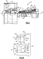
- the vane arc segment 60 is supported in the engine 20 by a structural spar piece 74, which is also shown in isolated views in Figures 3A and 3B.
- Figure 3A is a pressure side view and Figure 3B is a suction side view.
- the spar piece 74 is formed of a metallic alloy, such as but not limited to a single crystal nickel alloy.
- the spar piece 74 is comprised of a first spar platform 76a and first and second hollow legs 78/80. Although not shown, the spar platform 76a may have attachment features for supporting the spar piece 74 via an engine case or other fixed engine structure.
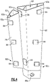
- the hollow legs 78/80 are also shown in an isolated view in Figure 4 , without the first platform 76a.
- each hollow leg 78/80 is cantilevered off of the first spar platform 76a and has a proximal end 82a at the spar platform 76a and an opposed distal end 82b. As will be discussed further below, the hollow legs 78/80 extend into the respective internal cavities 72 of the hollow ceramic airfoil section 62.
- the walls of the legs 78/80 define first and second sides 83a/83b and an adjoining third side 83c. Inside of the airfoil 68, the first side 83a faces toward the pressure side 68c of the airfoil 68, the second side faces toward the suction side 68d of the airfoil 68, and the third side faces toward the rib 70a.
- the walls of the legs 78/80 also encompass internal spar cavities 83 ( Figure 4 ), one or more of which may be subdivided by internal spar ribs. Such spar ribs may serve to stiffen the leg or legs 78/80 and carry bending and/or torsional loads.
- cooling air such as bleed air from the compressor section 24, may be provided through the cavities 83 to a downstream destination that is to be cooled.
- the downstream destination may be, but is not limited to, a turbine blade or a tangential on board injector (TOBI).
- each hollow leg 78/80 have raised bearing pads 84 that project therefrom.
- the bearing pads 84 are substantially rectangular, although other polygonal or rounded geometries may alternatively be used.
- the raised bearing pads 84 are integral to the walls of the legs 78/80.
- the raised bearing pads 84 may be formed by casting, machining, or combinations thereof, for example.
- multiple ones of the raised bearing pads 84 contact the walls 70 of the hollow ceramic airfoil section 62 and thereby support the hollow ceramic airfoil section 62 from within.
- Figure 5 depicts a representative example in which the raised bearing pad 84 is in areal contact with the wall 70.
- the term "areal contact” or variations thereof refers to contact between substantially the entire outward face of the raised bearing pad 84 and the wall 70.
- the outward face of each bearing pad 84 is contoured to match the localized contour of the wall 70 at the location of the bearing pad 84.
- each of the legs 78/80 has relatively few of the raised bearing pads 84 in comparison to other types of functional projections such as stand-offs that are used on baffles.
- each of the legs 78/80 includes a first group of the pads 84 at the proximal end 82a, a second group of the pads 84 at the distal end 82b, and a third group of the pads 84 intermediate the ends 82a/82b.
- a "group" of pads 84 are pads that lie in a common span range.
- the groups are spaced relatively far apart.
- the groups are spaced apart so as to maximize the wheelbase between adjacent groups while minimizing encroachment on other nearby design features.
- the legs 78/80 exclude the third group such that the first and second groups at the end 82a/82b are the only pads 84.
- the spar piece 74 further includes a second spar platform 76b that is secured directly to the distal end 82b of at least one of the hollow legs 78/80.
- one or both of the hollow legs 78/80 includes a lock orifice 86a and a lock pin 86b ( Figure 2B ) disposed through the lock orifice 86a.
- the lock pin 86b is of sufficient size such that it prevents the hollow leg 78 or 80 from being retracted through the internal cavity 72, thereby locking the spar piece 74 and hollow ceramic airfoil section 62 together.
- That leg 78/80 may be shorter such that it extends only a portion of the span of the cavity 72 of the airfoil 68.
- the shorter leg may also facilitate a reduction in thermal stress between the spar piece 74 and the ceramic airfoil 68.
- the other leg 78 may also have a lock orifice 86a for receiving a second lock pin.
- both legs 78/80 may have the lock orifices 86a and lock pins 86b to handle higher radial loads and/or moment force on the spar piece 74.
- support schemes for mounting vane segments formed of ceramic matrix composites are challenging due to lower material stress limits in comparison to high strength superalloys used for some traditional vane segments.
- traditional support schemes that utilize hooks or a series of rails can concentrate stresses, create aerodynamic loads, and/or create thermal stresses which may exceed material limits of ceramic matrix composites. Therefore, even though ceramic matrix composites may have many potential benefits, such benefits cannot be realized without a suitable support scheme.
- the legs 78/80 with the raised bearing pads 84 serve as support features to facilitate a low-stress mounting scheme from the inside of the airfoil 68, as opposed to an attachment scheme at the radial ends of the airfoil.
- combustion gases flow across the airfoil 68 and platforms 64/66.
- the flow causes aerodynamic loads, which are transmitted through the spar piece 74 to engine support structure(s).
- the raised bearing pads 84 are located at high load locations at which the airfoil 68 experiences maximum loads under the Durability or Structures Design Point (DDP & SDP, respectively).
- DDP & SDP Durability or Structures Design Point
- Such locations may be determined experimentally or by computer simulation.
- the locations are those at which the airfoil 68 experiences peak twist or bending deflection.
- Such locations may also be adjusted during a design phase by changing the location, angle, and/or presence of ribs.
- one or more of the raised bearing pads 84 may not be in contact with the walls 70 of the airfoil 68 when in a cold, non-operating condition.
- deflection of the airfoil 68 causes contact between two or more of the raised bearing pads 84 and the walls 70. In general, such deflection may be in an aft direction and radially outward direction. Therefore, raised bearing pads 84 that are on forward portions of the legs 78/80 may not be in contact with the walls 70, while raised bearing pads 84 that are on aft portions of the legs 78/80 may be in contact with the walls 70, such as the rib 70a.
Abstract
Description
- A gas turbine engine typically includes a fan section, a compressor section, a combustor section and a turbine section. Air entering the compressor section is compressed and delivered into the combustion section where it is mixed with fuel and ignited to generate a high-speed exhaust gas flow. The high-speed exhaust gas flow expands through the turbine section to drive the compressor and the fan section. The compressor section may include low and high pressure compressors, and the turbine section may also include low and high pressure turbines.
- Airfoils in the turbine section are typically formed of a superalloy and may include thermal barrier coatings to extend temperature capability and lifetime. Ceramic matrix composite ("CMC") materials are also being considered for airfoils. Among other attractive properties, CMCs have high temperature resistance. Despite this attribute, however, there are unique challenges to implementing CMCs in airfoils.
- A vane arc segment according to an example of the present disclosure includes a hollow ceramic airfoil section having walls defining an internal cavity, a trailing edge, a leading edge, a pressure side, and a suction side. A structural spar piece supports the hollow ceramic airfoil section. The structural spar piece has a first spar platform, and a hollow leg having a proximal end at the spar platform and an opposed distal end. The hollow leg extends into the internal cavity of the hollow ceramic airfoil section. The hollow leg defines an outer surface with raised bearing pads projecting therefrom. Multiple ones of the raised bearing pads contact the walls of the hollow ceramic airfoil section to support the hollow ceramic airfoil section, and a second spar platform is secured with the distal end of the leg.
- In a further embodiment of any of the foregoing embodiments, the leg has a first side facing toward the pressure side and a second side facing toward the suction side, and there are raised bearing pads on the first side and the second side.
- In a further embodiment of any of the foregoing embodiments, the walls of the hollow ceramic airfoil section define one or more ribs that divide the internal cavity into a plurality of cavities, the hollow leg has a third side that faces toward the one or more ribs, and there are bearing pads on the third side.
- In a further embodiment of any of the foregoing embodiments, the hollow leg includes an internal spar cavity that is fluidly isolated in the hollow ceramic airfoil section from the internal cavity.
- In a further embodiment of any of the foregoing embodiments, the distal end of the hollow leg includes a lock orifice and a lock pin disposed in the lock orifice.
- In a further embodiment of any of the foregoing embodiments, the multiple ones of the raised bearing pads that contact the walls are in areal contact with the walls.
- In a further embodiment of any of the foregoing embodiments, the structural spar piece is formed of a single crystal alloy.
- In a further embodiment of any of the foregoing embodiments, the hollow leg has a total of nine or fewer of the raised bearing pads.
- In a further embodiment of any of the foregoing embodiments, ones of the raised bearing pads that are on a same side of the hollow leg are spaced apart.
- In a further embodiment of any of the foregoing embodiments, the hollow ceramic airfoil section has at least one airfoil platform that is in contact with the spar platform.
- A vane arc segment according to an example of the present disclosure includes a hollow ceramic airfoil section having walls defining forward and aft internal cavities, a trailing edge, a leading edge, a pressure side, and a suction side; and a structural spar piece supporting the hollow ceramic airfoil section. The structural spar piece has a first spar platform, and first and second hollow legs each having a proximal end at the spar platform and an opposed distal end. The first hollow leg extends into the forward internal cavity and the second hollow leg extending into the aft internal cavity. The first and second hollow legs each define an outer surface with raised bearing pads projecting therefrom. The raised bearing pads contact the walls of the hollow ceramic airfoil section to support the hollow ceramic airfoil section, and a second spar platform secured with the distal end of at least one of the first or second hollow legs.
- In a further embodiment of any of the foregoing embodiments, one of the first or second hollow legs extends through the hollow ceramic airfoil section.
- In a further embodiment of any of the foregoing embodiments, each of the first and second hollow legs has a first side facing toward the pressure side and a second side facing toward the suction side, and there are raised bearing pads on the first side and the second side.
- In a further embodiment of any of the foregoing embodiments, each of the first and second hollow legs includes an internal spar cavity that is fluidly isolated in the hollow ceramic airfoil section from, respectively, the forward and aft internal cavities.
- In a further embodiment of any of the foregoing embodiments, the distal end of at least one of the first or second hollow legs includes a lock orifice and a lock pin disposed in the lock orifice.
- In a further embodiment of any of the foregoing embodiments, the structural spar piece is formed of a single crystal alloy.
- A gas turbine engine according to an example of the present disclosure includes a compressor section, a combustor in fluid communication with the compressor section, and a turbine section in fluid communication with the combustor. The turbine section has vane arc segments disposed about a central axis of the gas turbine engine. Each of the vane arc segments includes a hollow ceramic airfoil section having walls defining an internal cavity, a trailing edge, a leading edge, a pressure side, and a suction side, and a structural spar piece supporting the hollow ceramic airfoil section. The structural spar piece has a first spar platform, and a hollow leg having a proximal end at the spar platform and a distal end. The hollow leg extends into the internal cavity of the hollow ceramic airfoil section. The hollow leg defines an outer surface with raised bearing pads projecting therefrom. The raised bearing pads contact the walls of the hollow ceramic airfoil section to support the hollow ceramic airfoil section, and a second spar platform secured with the distal end of the leg.
- In a further embodiment of any of the foregoing embodiments, the leg has a first side facing toward the pressure side and a second side facing toward the suction side, and there are raised bearing pads on the first side and the second side.
- In a further embodiment of any of the foregoing embodiments, the hollow leg includes an internal spar cavity that is fluidly isolated in the hollow ceramic airfoil section from the internal cavity.
- In a further embodiment of any of the foregoing embodiments, the hollow ceramic airfoil section has at least one airfoil platform that is in contact with the spar platform.
- The various features and advantages of the present disclosure will become apparent to those skilled in the art from the following detailed description. The drawings that accompany the detailed description can be briefly described as follows.
-
Figure 1 illustrates a gas turbine engine. -
Figure 2A illustrates an expanded view of a vane arc segment. -
Figure 2B illustrates an assembled view of a vane arc segment. -
Figure 3A illustrates pressure side view of a spar piece. -
Figure 3B illustrates a suction side view of the spar piece. -
Figure 4 illustrates an isolated view of spar legs without a spar platform. -
Figure 5 illustrates a raised bearing pad in areal contact with a wall of an airfoil. -
Figure 1 schematically illustrates agas turbine engine 20. Thegas turbine engine 20 is disclosed herein as a two-spool turbofan that generally incorporates afan section 22, acompressor section 24, acombustor section 26 and aturbine section 28. Thefan section 22 drives air along a bypass flow path B in a bypass duct defined within ahousing 15 such as a fan case or nacelle, and also drives air along a core flow path C for compression and communication into thecombustor section 26 then expansion through theturbine section 28. Although depicted as a two-spool turbofan gas turbine engine in the disclosed non-limiting embodiment, it should be understood that the concepts described herein are not limited to use with two-spool turbofans as the teachings may be applied to other types of turbine engines including three-spool architectures. - The
exemplary engine 20 generally includes alow speed spool 30 and ahigh speed spool 32 mounted for rotation about an engine central longitudinal axis A relative to an engine static structure 36 viaseveral bearing systems 38. It should be understood thatvarious bearing systems 38 at various locations may alternatively or additionally be provided, and the location ofbearing systems 38 may be varied as appropriate to the application. - The
low speed spool 30 generally includes aninner shaft 40 that interconnects, a first (or low)pressure compressor 44 and a first (or low)pressure turbine 46. Theinner shaft 40 is connected to thefan 42 through a speed change mechanism, which in exemplarygas turbine engine 20 is illustrated as a gearedarchitecture 48 to drive afan 42 at a lower speed than thelow speed spool 30. Thehigh speed spool 32 includes anouter shaft 50 that interconnects a second (or high)pressure compressor 52 and a second (or high)pressure turbine 54. Acombustor 56 is arranged inexemplary gas turbine 20 between thehigh pressure compressor 52 and thehigh pressure turbine 54. Amid-turbine frame 57 of the engine static structure 36 may be arranged generally between thehigh pressure turbine 54 and thelow pressure turbine 46. Themid-turbine frame 57 furthersupports bearing systems 38 in theturbine section 28. Theinner shaft 40 and theouter shaft 50 are concentric and rotate via bearingsystems 38 about the engine central longitudinal axis A which is collinear with their longitudinal axes. - The core airflow is compressed by the
low pressure compressor 44 then thehigh pressure compressor 52, mixed and burned with fuel in thecombustor 56, then expanded through thehigh pressure turbine 54 andlow pressure turbine 46. Themid-turbine frame 57 includesairfoils 59 which are in the core airflow path C. Theturbines low speed spool 30 andhigh speed spool 32 in response to the expansion. It will be appreciated that each of the positions of thefan section 22,compressor section 24,combustor section 26,turbine section 28, and fandrive gear system 48 may be varied. For example,gear system 48 may be located aft of the low pressure compressor, or aft of thecombustor section 26 or even aft ofturbine section 28, andfan 42 may be positioned forward or aft of the location ofgear system 48. - The
engine 20 in one example is a high-bypass geared aircraft engine. In a further example, theengine 20 bypass ratio is greater than about six (6), with an example embodiment being greater than about ten (10), the gearedarchitecture 48 is an epicyclic gear train, such as a planetary gear system or other gear system, with a gear reduction ratio of greater than about 2.3 and thelow pressure turbine 46 has a pressure ratio that is greater than about five. In one disclosed embodiment, theengine 20 bypass ratio is greater than about ten (10:1), the fan diameter is significantly larger than that of thelow pressure compressor 44, and thelow pressure turbine 46 has a pressure ratio that is greater than about five 5:1.Low pressure turbine 46 pressure ratio is pressure measured prior to inlet oflow pressure turbine 46 as related to the pressure at the outlet of thelow pressure turbine 46 prior to an exhaust nozzle. The gearedarchitecture 48 may be an epicycle gear train, such as a planetary gear system or other gear system, with a gear reduction ratio of greater than about 2.3:1 and less than about 5:1. It should be understood, however, that the above parameters are only exemplary of one embodiment of a geared architecture engine and that the present invention is applicable to other gas turbine engines including direct drive turbofans. - A significant amount of thrust is provided by the bypass flow B due to the high bypass ratio. The
fan section 22 of theengine 20 is designed for a particular flight condition -- typically cruise at about 0.8 Mach and about 35,000 feet (10,668 meters). The flight condition of 0.8 Mach and 35,000 ft (10,668 meters), with the engine at its best fuel consumption - also known as "bucket cruise Thrust Specific Fuel Consumption ('TSFC')" - is the industry standard parameter of lbm of fuel being burned divided by lbf of thrust the engine produces at that minimum point. "Low fan pressure ratio" is the pressure ratio across the fan blade alone, without a Fan Exit Guide Vane ("FEGV") system. The low fan pressure ratio as disclosed herein according to one non-limiting embodiment is less than about 1.45. "Low corrected fan tip speed" is the actual fan tip speed in ft/sec divided by an industry standard temperature correction of [(Tram °R) / (518.7 °R)]0.5. The "Low corrected fan tip speed" as disclosed herein according to one non-limiting embodiment is less than about 1150 ft / second (350.5 meters/second). -
Figure 2A illustrates a schematic expanded view of a representativevane arc segment 60 of a vane ring assembly from theturbine section 28 of theengine 20, andFigure 2B illustrates a fully assembled view of the vane arc segment 60 (without a portion of the pressure side wall so that the interior of the vane can be seen). Thevane arc segments 60 are situated in a circumferential row about the engine central axis A. Although thevane arc segment 60 is shown and described with reference to use in theturbine section 28, it is to be understood that the examples herein are also applicable to vanes in other sections of theengine 20. - The
vane arc segment 60 is comprised of a hollowceramic airfoil section 62. The hollowceramic airfoil section 62 includes first andsecond platforms 64/66 and anairfoil 68 that extends between theplatforms 64/66. In this example, thefirst platform 64 is a radially outer platform and thesecond platform 66 is a radially inner platform. Theairfoil 68 is formed ofwalls 70 that define aleading edge 68a, a trailingedge 68b, pressure andsuction sides 68c/68d, and at least oneinternal cavity 72. In this example, thewalls 70 include arib 70a such that there are at least twosuch cavities 72, which may also be considered to be a forward cavity and an aft cavity. - The hollow
ceramic airfoil section 62 is continuous in that theplatforms 64/66 andairfoil 68 constitute a one-piece body. As an example, the hollowceramic airfoil section 62 is formed of a ceramic material, such as a ceramic matrix composite. For instance, the ceramic matrix composite is formed of ceramic fibers that are disposed in a ceramic matrix. The ceramic matrix composite may be, but is not limited to, a SiC/SiC ceramic matrix composite in which SiC fibers are disposed within a SiC matrix. The ceramic fibers are provided in fiber plies. The plies may be woven or unidirectional and may collectively include plies of the same or different fiber weave configurations. One or more of the plies may be continuous through thefirst platform 64, theairfoil 68, and thesecond platform 68. - The
vane arc segment 60 is supported in theengine 20 by astructural spar piece 74, which is also shown in isolated views inFigures 3A and 3B. Figure 3A is a pressure side view andFigure 3B is a suction side view. Thespar piece 74 is formed of a metallic alloy, such as but not limited to a single crystal nickel alloy. Thespar piece 74 is comprised of afirst spar platform 76a and first and secondhollow legs 78/80. Although not shown, thespar platform 76a may have attachment features for supporting thespar piece 74 via an engine case or other fixed engine structure. Thehollow legs 78/80 are also shown in an isolated view inFigure 4 , without thefirst platform 76a. As will be appreciated, although thespar piece 74 has two hollow legs in this example, it may alternatively have a single hollow leg or three or more hollow legs. Eachhollow leg 78/80 is cantilevered off of thefirst spar platform 76a and has aproximal end 82a at thespar platform 76a and an opposeddistal end 82b. As will be discussed further below, thehollow legs 78/80 extend into the respectiveinternal cavities 72 of the hollowceramic airfoil section 62. - The walls of the
legs 78/80 define first andsecond sides 83a/83b and an adjoiningthird side 83c. Inside of theairfoil 68, thefirst side 83a faces toward thepressure side 68c of theairfoil 68, the second side faces toward thesuction side 68d of theairfoil 68, and the third side faces toward therib 70a. The walls of thelegs 78/80 also encompass internal spar cavities 83 (Figure 4 ), one or more of which may be subdivided by internal spar ribs. Such spar ribs may serve to stiffen the leg orlegs 78/80 and carry bending and/or torsional loads. The walls of thelegs 78/80 are solid and continuous (without through-holes) such that theinternal spar cavities 83 are fluidly isolated from theinternal cavities 72 inside of theairfoil 68. In this regard, cooling air, such as bleed air from thecompressor section 24, may be provided through thecavities 83 to a downstream destination that is to be cooled. The downstream destination may be, but is not limited to, a turbine blade or a tangential on board injector (TOBI). - The outer surfaces of each
hollow leg 78/80 have raisedbearing pads 84 that project therefrom. In the example shown, the bearingpads 84 are substantially rectangular, although other polygonal or rounded geometries may alternatively be used. For instance, the raisedbearing pads 84 are integral to the walls of thelegs 78/80. The raisedbearing pads 84 may be formed by casting, machining, or combinations thereof, for example. As depicted inFigure 2B , multiple ones of the raisedbearing pads 84 contact thewalls 70 of the hollowceramic airfoil section 62 and thereby support the hollowceramic airfoil section 62 from within. For instance,Figure 5 depicts a representative example in which the raisedbearing pad 84 is in areal contact with thewall 70. As used herein, the term "areal contact" or variations thereof refers to contact between substantially the entire outward face of the raisedbearing pad 84 and thewall 70. In this regard, the outward face of each bearingpad 84 is contoured to match the localized contour of thewall 70 at the location of thebearing pad 84. - The
legs 78/80 have relatively few of the raisedbearing pads 84 in comparison to other types of functional projections such as stand-offs that are used on baffles. For instance, in the example shown, each of thelegs 78/80 includes a first group of thepads 84 at theproximal end 82a, a second group of thepads 84 at thedistal end 82b, and a third group of thepads 84 intermediate theends 82a/82b. A "group" ofpads 84 are pads that lie in a common span range. The groups are spaced relatively far apart. For example, the groups are spaced apart so as to maximize the wheelbase between adjacent groups while minimizing encroachment on other nearby design features. In further examples, thelegs 78/80 exclude the third group such that the first and second groups at theend 82a/82b are theonly pads 84. - The
spar piece 74 further includes asecond spar platform 76b that is secured directly to thedistal end 82b of at least one of thehollow legs 78/80. For example, one or both of thehollow legs 78/80 includes alock orifice 86a and alock pin 86b (Figure 2B ) disposed through thelock orifice 86a. Thelock pin 86b is of sufficient size such that it prevents thehollow leg internal cavity 72, thereby locking thespar piece 74 and hollowceramic airfoil section 62 together. If one of thehollow legs 78/80 does not have a lock orifice, thatleg 78/80 may be shorter such that it extends only a portion of the span of thecavity 72 of theairfoil 68. The shorter leg may also facilitate a reduction in thermal stress between thespar piece 74 and theceramic airfoil 68. Optionally, as shown in dashed lines inFigure 3A , theother leg 78 may also have alock orifice 86a for receiving a second lock pin. For example, bothlegs 78/80 may have thelock orifices 86a and lock pins 86b to handle higher radial loads and/or moment force on thespar piece 74. - In general, support schemes for mounting vane segments formed of ceramic matrix composites are challenging due to lower material stress limits in comparison to high strength superalloys used for some traditional vane segments. For instance, traditional support schemes that utilize hooks or a series of rails can concentrate stresses, create aerodynamic loads, and/or create thermal stresses which may exceed material limits of ceramic matrix composites. Therefore, even though ceramic matrix composites may have many potential benefits, such benefits cannot be realized without a suitable support scheme. In this regard, the
legs 78/80 with the raisedbearing pads 84 serve as support features to facilitate a low-stress mounting scheme from the inside of theairfoil 68, as opposed to an attachment scheme at the radial ends of the airfoil. - During operation of the
engine 20 combustion gases flow across theairfoil 68 andplatforms 64/66. The flow causes aerodynamic loads, which are transmitted through thespar piece 74 to engine support structure(s). For example, the raisedbearing pads 84 are located at high load locations at which theairfoil 68 experiences maximum loads under the Durability or Structures Design Point (DDP & SDP, respectively). Such locations may be determined experimentally or by computer simulation. As an example, the locations are those at which theairfoil 68 experiences peak twist or bending deflection. Such locations may also be adjusted during a design phase by changing the location, angle, and/or presence of ribs. In this regard, one or more of the raisedbearing pads 84 may not be in contact with thewalls 70 of theairfoil 68 when in a cold, non-operating condition. However, under operating temperatures and aerodynamic forces, deflection of theairfoil 68 causes contact between two or more of the raisedbearing pads 84 and thewalls 70. In general, such deflection may be in an aft direction and radially outward direction. Therefore, raised bearingpads 84 that are on forward portions of thelegs 78/80 may not be in contact with thewalls 70, while raised bearingpads 84 that are on aft portions of thelegs 78/80 may be in contact with thewalls 70, such as therib 70a. - Although a combination of features is shown in the illustrated examples, not all of them need to be combined to realize the benefits of various embodiments of this disclosure. In other words, a system designed according to an embodiment of this disclosure will not necessarily include all of the features shown in any one of the Figures or all of the portions schematically shown in the Figures. Moreover, selected features of one example embodiment may be combined with selected features of other example embodiments.
- The preceding description is exemplary rather than limiting in nature. Variations and modifications to the disclosed examples may become apparent to those skilled in the art that do not necessarily depart from this disclosure. The scope of legal protection given to this disclosure can only be determined by studying the following claims.
Claims (15)
- A vane arc segment (60) comprising:a hollow ceramic airfoil section (62) having walls (70) defining at least one internal cavity (72), a trailing edge (68b), a leading edge (68a), a pressure side (68c), and a suction side (68d); anda structural spar piece (74) supporting the hollow ceramic airfoil section (62), the structural spar piece (74) having:a first spar platform (76a),at least one hollow leg (78, 80) having a proximal end (82a) at the spar platform (76a) and an opposed distal end (82b), the hollow leg (78, 80) extending into the internal cavity (72) of the hollow ceramic airfoil section (62),the hollow leg (78, 80) defining an outer surface with raised bearing pads (84) projecting therefrom,multiple ones of the raised bearing pads (84) contacting the walls (70) of the hollow ceramic airfoil section (62) to support the hollow ceramic airfoil section (62), anda second spar platform (76b) secured with the distal end (82b) of the leg (78, 80).
- The vane arc segment (60) as recited in claim 1, wherein the leg (78, 80) has a first side (83a) facing toward the pressure side (68c) and a second side (83b) facing toward the suction side (68d), and there are raised bearing pads (84) on the first side (83a) and the second side (83b).
- The vane arc segment (60) as recited in claim 2, wherein the walls (70) of the hollow ceramic airfoil section (62) define one or more ribs that divide the internal cavity (72) into a plurality of cavities, the hollow leg (78, 80) has a third side (83 c) that faces toward the one or more ribs, and there are bearing pads (84) on the third side (83c).
- The vane arc segment (60) as recited in claim 1, 2 or 3, wherein the hollow leg (78, 80) includes an internal spar cavity (83) that is fluidly isolated in the hollow ceramic airfoil section (62) from the internal cavity (72).
- The vane arc segment (60) as recited in any preceding claim, wherein the distal end (82b) of the hollow leg (78, 80) includes a lock orifice (86a) and a lock pin (86b) disposed in the lock orifice (86a).
- The vane arc segment (60) as recited in any preceding claim, wherein the multiple ones of the raised bearing pads (84) that contact the walls (70) are in areal contact with the walls (70).
- The vane arc segment (60) as recited in any preceding claim, wherein the structural spar piece (74) is formed of a single crystal alloy.
- The vane arc segment (60) as recited in any preceding claim, wherein the hollow leg (78, 80) has a total of nine or fewer of the raised bearing pads (84).
- The vane arc segment (60) as recited in any preceding claim, wherein ones of the raised bearing pads (84) that are on a same side of the hollow leg (78, 80) are spaced apart.
- The vane arc segment (60) as recited in any preceding claim, wherein the hollow ceramic airfoil section (62) has at least one airfoil platform (64, 66) that is in contact with the spar platform (76a, 76b).
- The vane arc segment (60) as recited in any preceding claim, wherein the at least one internal cavity comprises forward and aft internal cavities (72); and
the at least one hollow leg comprises first and second hollow legs (78, 80), the first hollow leg (78) extending into the forward internal cavity (72) and the second hollow leg (80) extending into the aft internal cavity (72). - The vane arc segment (60) as recited in claim 11, wherein one of the first or second hollow legs (78, 80) extends through the hollow ceramic airfoil section (62).
- The vane arc segment (60) as recited in claim 11 or 12, wherein each of the first and second hollow legs (78, 80) includes an internal spar cavity (83) that is fluidly isolated in the hollow ceramic airfoil section (62) from, respectively, the forward and aft internal cavities (72).
- The vane arc segment (60) as recited in claim 11, 12 or 13, wherein the distal end (82b) of at least one of the first or second hollow legs (78, 80) includes a/the lock orifice (86a) and a/the lock pin (86b) disposed in the lock orifice (86a).
- A gas turbine engine (20) comprising:a compressor section (24);a combustor in fluid communication with the compressor section (24); anda turbine section (28) in fluid communication with the combustor, the turbine section (28) having vane arc segments (60) disposed about a central axis (A) of the gas turbine engine (20), each of the vane arc segments (60) being a vane arc segment according to any preceding claim.
Applications Claiming Priority (1)
| Application Number | Priority Date | Filing Date | Title |
|---|---|---|---|
| US17/086,893 US11448075B2 (en) | 2020-11-02 | 2020-11-02 | CMC vane arc segment with cantilevered spar |
Publications (1)
| Publication Number | Publication Date |
|---|---|
| EP4001592A1 true EP4001592A1 (en) | 2022-05-25 |
Family
ID=78414564
Family Applications (1)
| Application Number | Title | Priority Date | Filing Date |
|---|---|---|---|
| EP21205653.5A Pending EP4001592A1 (en) | 2020-11-02 | 2021-10-29 | Cmc vane arc segment with cantilevered spar |
Country Status (2)
| Country | Link |
|---|---|
| US (1) | US11448075B2 (en) |
| EP (1) | EP4001592A1 (en) |
Cited By (2)
| Publication number | Priority date | Publication date | Assignee | Title |
|---|---|---|---|---|
| FR3136811A1 (en) * | 2022-06-21 | 2023-12-22 | Safran Aircraft Engines | TURBINE WHEEL WITH CMC BLADE AND STRUCTURAL MAST RETAINED BY PIN |
| FR3136812A1 (en) * | 2022-06-21 | 2023-12-22 | Safran Aircraft Engines | TURBINE WHEEL WITH CMC BLADE AND N-UPLET STRUCTURAL MAST |
Families Citing this family (2)
| Publication number | Priority date | Publication date | Assignee | Title |
|---|---|---|---|---|
| US11603765B1 (en) * | 2021-07-16 | 2023-03-14 | Raytheon Technologies Corporation | Airfoil assembly with fiber-reinforced composite rings and toothed exit slot |
| US20230392506A1 (en) * | 2022-06-03 | 2023-12-07 | Raytheon Technologies Corporation | Vane arc segment with single-sided platforms |
Citations (4)
| Publication number | Priority date | Publication date | Assignee | Title |
|---|---|---|---|---|
| US20100068034A1 (en) * | 2008-09-18 | 2010-03-18 | Schiavo Anthony L | CMC Vane Assembly Apparatus and Method |
| US20190153879A1 (en) * | 2017-11-20 | 2019-05-23 | Rolls-Royce Corporation | Airfoil for a gas turbine engine having insulating materials |
| US20190368360A1 (en) * | 2018-06-01 | 2019-12-05 | Rolls-Royce North American Technologies Inc. | Turbine vane assembly with ceramic matrix composite components |
| EP3670842A1 (en) * | 2018-12-20 | 2020-06-24 | Rolls-Royce plc | Sliding ceramic matrix composite vane assembly for gas turbine engines |
Family Cites Families (9)
| Publication number | Priority date | Publication date | Assignee | Title |
|---|---|---|---|---|
| US3301527A (en) * | 1965-05-03 | 1967-01-31 | Gen Electric | Turbine diaphragm structure |
| US6224339B1 (en) * | 1998-07-08 | 2001-05-01 | Allison Advanced Development Company | High temperature airfoil |
| US6283708B1 (en) * | 1999-12-03 | 2001-09-04 | United Technologies Corporation | Coolable vane or blade for a turbomachine |
| US8142137B2 (en) * | 2008-11-26 | 2012-03-27 | Alstom Technology Ltd | Cooled gas turbine vane assembly |
| US10309240B2 (en) | 2015-07-24 | 2019-06-04 | General Electric Company | Method and system for interfacing a ceramic matrix composite component to a metallic component |
| US10612385B2 (en) * | 2016-03-07 | 2020-04-07 | Rolls-Royce Corporation | Turbine blade with heat shield |
| US10808560B2 (en) * | 2018-06-20 | 2020-10-20 | Rolls-Royce Corporation | Turbine vane assembly with ceramic matrix composite components |
| US10774665B2 (en) | 2018-07-31 | 2020-09-15 | General Electric Company | Vertically oriented seal system for gas turbine vanes |
| US10883371B1 (en) * | 2019-06-21 | 2021-01-05 | Rolls-Royce Plc | Ceramic matrix composite vane with trailing edge radial cooling |
-
2020
- 2020-11-02 US US17/086,893 patent/US11448075B2/en active Active
-
2021
- 2021-10-29 EP EP21205653.5A patent/EP4001592A1/en active Pending
Patent Citations (4)
| Publication number | Priority date | Publication date | Assignee | Title |
|---|---|---|---|---|
| US20100068034A1 (en) * | 2008-09-18 | 2010-03-18 | Schiavo Anthony L | CMC Vane Assembly Apparatus and Method |
| US20190153879A1 (en) * | 2017-11-20 | 2019-05-23 | Rolls-Royce Corporation | Airfoil for a gas turbine engine having insulating materials |
| US20190368360A1 (en) * | 2018-06-01 | 2019-12-05 | Rolls-Royce North American Technologies Inc. | Turbine vane assembly with ceramic matrix composite components |
| EP3670842A1 (en) * | 2018-12-20 | 2020-06-24 | Rolls-Royce plc | Sliding ceramic matrix composite vane assembly for gas turbine engines |
Cited By (2)
| Publication number | Priority date | Publication date | Assignee | Title |
|---|---|---|---|---|
| FR3136811A1 (en) * | 2022-06-21 | 2023-12-22 | Safran Aircraft Engines | TURBINE WHEEL WITH CMC BLADE AND STRUCTURAL MAST RETAINED BY PIN |
| FR3136812A1 (en) * | 2022-06-21 | 2023-12-22 | Safran Aircraft Engines | TURBINE WHEEL WITH CMC BLADE AND N-UPLET STRUCTURAL MAST |
Also Published As
| Publication number | Publication date |
|---|---|
| US20220136393A1 (en) | 2022-05-05 |
| US11448075B2 (en) | 2022-09-20 |
Similar Documents
| Publication | Publication Date | Title |
|---|---|---|
| EP4001592A1 (en) | Cmc vane arc segment with cantilevered spar | |
| US11035243B2 (en) | Seal assembly for gas turbine engines | |
| EP3892822B1 (en) | Vane support system | |
| EP4015771B1 (en) | Vane arc segment with thermal insulation element | |
| EP3974617B1 (en) | Ceramic gas turbine engine airfoil with 3 zones film cooling hole pattern having different pitch | |
| US10753368B2 (en) | Multi-piece non-linear airfoil | |
| EP3825519A1 (en) | Vane with collar | |
| EP3825518B1 (en) | Vane retention assembly | |
| US11242762B2 (en) | Vane with collar | |
| EP4030035B1 (en) | Vane segment with pin mount and anti-rotation stabilizer rod | |
| US11655758B1 (en) | CMC vane mate face flanges with through-ply seal slots | |
| EP4033071A1 (en) | Vane with pin mount and anti-rotation | |
| US11719130B2 (en) | Vane system with continuous support ring | |
| EP3808940A1 (en) | Cmc airfoil with cooling holes | |
| US11668199B2 (en) | Vane arc segment with radially projecting flanges | |
| US20230366321A1 (en) | Ceramic vane ring-strut-ring attachment configuration | |
| EP3865669B1 (en) | Vane arc segment platform flange for a gas turbine engine with cap | |
| US11708765B1 (en) | Gas turbine engine article with branched flange | |
| US11603770B2 (en) | Vane assembly with integrated nozzle tube | |
| EP4067620B1 (en) | Airfoil with radially-spaced ribs and interlocking tabs, and gas turbine engine | |
| EP4215722A1 (en) | Turbine section with ceramic support rings and ceramic vane arc segments | |
| EP4283096A1 (en) | Cmc vane with flange having sloped radial face | |
| US20230383663A1 (en) | Turbine engine with tobi supporting vanes |
Legal Events
| Date | Code | Title | Description |
|---|---|---|---|
| PUAI | Public reference made under article 153(3) epc to a published international application that has entered the european phase |
Free format text: ORIGINAL CODE: 0009012 |
|
| STAA | Information on the status of an ep patent application or granted ep patent |
Free format text: STATUS: THE APPLICATION HAS BEEN PUBLISHED |
|
| AK | Designated contracting states |
Kind code of ref document: A1 Designated state(s): AL AT BE BG CH CY CZ DE DK EE ES FI FR GB GR HR HU IE IS IT LI LT LU LV MC MK MT NL NO PL PT RO RS SE SI SK SM TR |
|
| STAA | Information on the status of an ep patent application or granted ep patent |
Free format text: STATUS: REQUEST FOR EXAMINATION WAS MADE |
|
| 17P | Request for examination filed |
Effective date: 20221125 |
|
| RBV | Designated contracting states (corrected) |
Designated state(s): AL AT BE BG CH CY CZ DE DK EE ES FI FR GB GR HR HU IE IS IT LI LT LU LV MC MK MT NL NO PL PT RO RS SE SI SK SM TR |
|
| RAP3 | Party data changed (applicant data changed or rights of an application transferred) |
Owner name: RTX CORPORATION |