EP4001550A1 - Lightweight modular tower for telecommunications equipment - Google Patents
Lightweight modular tower for telecommunications equipment Download PDFInfo
- Publication number
- EP4001550A1 EP4001550A1 EP21204727.8A EP21204727A EP4001550A1 EP 4001550 A1 EP4001550 A1 EP 4001550A1 EP 21204727 A EP21204727 A EP 21204727A EP 4001550 A1 EP4001550 A1 EP 4001550A1
- Authority
- EP
- European Patent Office
- Prior art keywords
- uprights
- central tube
- telecommunications equipment
- tower
- modular tower
- Prior art date
- Legal status (The legal status is an assumption and is not a legal conclusion. Google has not performed a legal analysis and makes no representation as to the accuracy of the status listed.)
- Granted
Links
Images


Classifications
-
- E—FIXED CONSTRUCTIONS
- E04—BUILDING
- E04H—BUILDINGS OR LIKE STRUCTURES FOR PARTICULAR PURPOSES; SWIMMING OR SPLASH BATHS OR POOLS; MASTS; FENCING; TENTS OR CANOPIES, IN GENERAL
- E04H12/00—Towers; Masts or poles; Chimney stacks; Water-towers; Methods of erecting such structures
- E04H12/02—Structures made of specified materials
- E04H12/08—Structures made of specified materials of metal
- E04H12/10—Truss-like structures
-
- E—FIXED CONSTRUCTIONS
- E04—BUILDING
- E04H—BUILDINGS OR LIKE STRUCTURES FOR PARTICULAR PURPOSES; SWIMMING OR SPLASH BATHS OR POOLS; MASTS; FENCING; TENTS OR CANOPIES, IN GENERAL
- E04H12/00—Towers; Masts or poles; Chimney stacks; Water-towers; Methods of erecting such structures
- E04H12/34—Arrangements for erecting or lowering towers, masts, poles, chimney stacks, or the like
- E04H12/342—Arrangements for stacking tower sections on top of each other
-
- H—ELECTRICITY
- H01—ELECTRIC ELEMENTS
- H01Q—ANTENNAS, i.e. RADIO AERIALS
- H01Q1/00—Details of, or arrangements associated with, antennas
- H01Q1/12—Supports; Mounting means
- H01Q1/1242—Rigid masts specially adapted for supporting an aerial
-
- Y—GENERAL TAGGING OF NEW TECHNOLOGICAL DEVELOPMENTS; GENERAL TAGGING OF CROSS-SECTIONAL TECHNOLOGIES SPANNING OVER SEVERAL SECTIONS OF THE IPC; TECHNICAL SUBJECTS COVERED BY FORMER USPC CROSS-REFERENCE ART COLLECTIONS [XRACs] AND DIGESTS
- Y02—TECHNOLOGIES OR APPLICATIONS FOR MITIGATION OR ADAPTATION AGAINST CLIMATE CHANGE
- Y02E—REDUCTION OF GREENHOUSE GAS [GHG] EMISSIONS, RELATED TO ENERGY GENERATION, TRANSMISSION OR DISTRIBUTION
- Y02E10/00—Energy generation through renewable energy sources
- Y02E10/70—Wind energy
- Y02E10/728—Onshore wind turbines
Definitions
- the present invention relates to a structure from which towers for supporting antennas or telecommunications equipment are obtained, the purpose of which is to offer a modular, lightweight, resistant, economical and multipurpose structure.
- the proposed lightweight modular tower for telecommunications antennas fully solves the problems previously set forth in each and every one of the aspects discussed, based on a simple but highly effective solution.
- the structure of the invention is made up of a series of modules that can be vertically coupled until the desired height is obtained, which are finished with a top closure that can be removed to later expand the structure of the tower, modules wherein a vertical central tube and a series of perimeter uprights participate, which are linked together by means of horizontal rings, concentric to the main central tube, all of them based on a tubular structure, while said perimeter envelope is linked to the central tube through a lattice structure in which diagonal and horizontal bars participate, arranged in three vertical planes equiangularly distributed over the central tube and defining three independent holes, so that one of them can be used as a hole for the ascent of the operators, through the corresponding ladder parallel to the central tube, and in the other two, horizontal platforms can be arranged on which said operators can work.
- the modules will be fixed to each other by means of both the uprights and the central tube thereof by means of the complementary flanges established in correspondence with the upper and lower ends thereof, thus being able to easily adapt the height of the tower to the specific needs of each case.
- the tower will be anchored to the corresponding foundation, such that the initial modules will have a frustoconical configuration (with the uprights thereof slightly inclined), while the upper modules will have a configuration wherein said uprights are totally vertical.
- the configuration of the uprights means that the equipment or antennas to be installed can be directly fixed to the uprights, thus simplifying the structure, which has a very positive effect in terms of costs and weight reduction.
- said wiring can be separated in order to make the facilities of different operators independent, wiring that will be internally guided through the different vertical tubular uprights, as well as through the horizontal uprights.
- Figure 8 shows a perspective detail view of the tower at the level of the upper end thereof, the arrangement of the safety platform for the corresponding operator being observed.
- the tower of the invention is made up of a series of modules obtained from hollow round tubes, wherein a vertical central tube (1) and a series of perimeter uprights (2), specifically three, participate, which are linked together by means of horizontal rings (6), concentric to the central tube (1), forming an envelope that is linked to the central tube through a lattice structure in which diagonal bars (4) and horizontal bars (3) participate, which are fixed to plates (5) associated with both the uprights (2) and the central tube (1), and which are distributed forming three vertical planes equiangularly distributed over the central tube (1) defining three independent holes.
- Both the uprights (2) and the central tube (1) are finished in flanges (7) the screwing of which enables some modules to be linked to others, so that the first of the modules or lower module will be partially embedded in the corresponding foundation (10), this module being able to have the uprights (2) thereof slightly inclined, in order to determine a frustoconical structure to reinforce the lower area of the tower, if necessary, or said uprights (2) to be completely vertical, as occurs with the case of the modules that participate in the middle and upper area of the tower, all of this as shown in Figure 1 .
- the structure will be finished at the top with a top module (9), in which the uprights are linked to the central tube by means of bends and a connecting part (11).
- the described structure defines three independent vertical holes in the mounting thereof, such that one of them is used as a means of ascent for the operators (12), via the corresponding ladder (13) linked to the central tube (1) while the other two can house platforms (8) at different heights on which the corresponding operator (12) can work comfortably and safely.
- the equipment (14) can be directly mounted on the uprights (2) or, if required, on supports (15) that are also fixed to said uprights (2).
Landscapes
- Engineering & Computer Science (AREA)
- Architecture (AREA)
- Civil Engineering (AREA)
- Structural Engineering (AREA)
- Life Sciences & Earth Sciences (AREA)
- Chemical & Material Sciences (AREA)
- Materials Engineering (AREA)
- Wood Science & Technology (AREA)
- Support Of Aerials (AREA)
- Radiation-Therapy Devices (AREA)
- Suspension Of Electric Lines Or Cables (AREA)
Abstract
Description
- The present invention relates to a structure from which towers for supporting antennas or telecommunications equipment are obtained, the purpose of which is to offer a modular, lightweight, resistant, economical and multipurpose structure.
- Although the preferred field of application of the invention is the telecommunications sector, it is not ruled out that the invention is applicable in other fields wherein similar performance is required, such as wind turbine towers, support for advertising billboards or even power line support.
- In the field of telecommunications, as well as other areas in which lattice towers are used as a means of supporting equipment, these towers usually have a structure that, while fulfilling the functions for which they have been intended, have the following limitations or problems:
- They are expensive structures, due to the complex assembly and manufacture thereof.
- They are heavy structures.
- Their resistance can be compromised if the equipment installed on it is modified.
- Access to such equipment is not easy, which is further complicated when the structure is shared between several operators.
- Once the structure is finished, it is immovable, i.e., it cannot be expanded.
- The proposed lightweight modular tower for telecommunications antennas fully solves the problems previously set forth in each and every one of the aspects discussed, based on a simple but highly effective solution.
- To do this, and more specifically, the structure of the invention is made up of a series of modules that can be vertically coupled until the desired height is obtained, which are finished with a top closure that can be removed to later expand the structure of the tower, modules wherein a vertical central tube and a series of perimeter uprights participate, which are linked together by means of horizontal rings, concentric to the main central tube, all of them based on a tubular structure, while said perimeter envelope is linked to the central tube through a lattice structure in which diagonal and horizontal bars participate, arranged in three vertical planes equiangularly distributed over the central tube and defining three independent holes, so that one of them can be used as a hole for the ascent of the operators, through the corresponding ladder parallel to the central tube, and in the other two, horizontal platforms can be arranged on which said operators can work.
- The modules will be fixed to each other by means of both the uprights and the central tube thereof by means of the complementary flanges established in correspondence with the upper and lower ends thereof, thus being able to easily adapt the height of the tower to the specific needs of each case.
- If necessary, additional supports for telecommunications equipment could be fixed on the uprights themselves, although preferably, and as previously mentioned, this equipment will be directly fixed to the uprights of the tower.
- The tower will be anchored to the corresponding foundation, such that the initial modules will have a frustoconical configuration (with the uprights thereof slightly inclined), while the upper modules will have a configuration wherein said uprights are totally vertical.
- This confers a great modularity and therefore, versatility to the tower.
- The configuration of the uprights means that the equipment or antennas to be installed can be directly fixed to the uprights, thus simplifying the structure, which has a very positive effect in terms of costs and weight reduction.
- Likewise, the accessibility to the equipment is maximum, with great comfort and with total safety.
- Regarding the wiring guidance, since it is a star structure, said wiring can be separated in order to make the facilities of different operators independent, wiring that will be internally guided through the different vertical tubular uprights, as well as through the horizontal uprights.
- From this structuring, the following advantages are derived:
- It enables the descending load from the top to be distributed, both to the weight and to the wind at 50% of the height of the tower.
- It facilitates the installation and removal of new equipment on the structure itself, with great accessibility and safety.
- Easy restructuring of the structure itself in the event of stresses provided for the tower being increased.
- Lightweight, resistant and cost-effective structure.
- Separation of wiring by operator/independence of facilities.
- In order to complement the description being made and with the object of helping to better understand the features of the invention, in accordance with a preferred practical exemplary embodiment thereof, said description is accompanied, as an integral part thereof, by a set of drawings where, in an illustrative and non-limiting manner, the following has been represented:
-
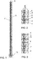
Figure 1 shows a profile view of a lightweight modular tower for communication antennas made according to the object of the present invention. -
Figure 2 shows a detail of the tower ofFigure 1 at the level of the top thereof. -
Figure 3 shows a detail of the tower ofFigure 1 at the level of the upper middle area thereof. -
Figure 4 shows a plan view of the tower ofFigure 1 . -
Figure 5 shows a view similar to that ofFigure 3 , but in which an operator is shown in a working situation; it shows a tower on which additional supports have been installed for fixing equipment. -
Figure 6 shows a plan view of the tower, in which the arrangement of the work platforms for the operators can be seen. -
Figure 7 shows a view similar to that ofFigure 1 , but in which different equipment from different operators are mounted at different heights on the tower. - Finally,
Figure 8 shows a perspective detail view of the tower at the level of the upper end thereof, the arrangement of the safety platform for the corresponding operator being observed. - In view of the outlined figures, it can be seen how the tower of the invention is made up of a series of modules obtained from hollow round tubes, wherein a vertical central tube (1) and a series of perimeter uprights (2), specifically three, participate, which are linked together by means of horizontal rings (6), concentric to the central tube (1), forming an envelope that is linked to the central tube through a lattice structure in which diagonal bars (4) and horizontal bars (3) participate, which are fixed to plates (5) associated with both the uprights (2) and the central tube (1), and which are distributed forming three vertical planes equiangularly distributed over the central tube (1) defining three independent holes.
- Both the uprights (2) and the central tube (1) are finished in flanges (7) the screwing of which enables some modules to be linked to others, so that the first of the modules or lower module will be partially embedded in the corresponding foundation (10), this module being able to have the uprights (2) thereof slightly inclined, in order to determine a frustoconical structure to reinforce the lower area of the tower, if necessary, or said uprights (2) to be completely vertical, as occurs with the case of the modules that participate in the middle and upper area of the tower, all of this as shown in
Figure 1 . - The structure will be finished at the top with a top module (9), in which the uprights are linked to the central tube by means of bends and a connecting part (11).
- As can be clearly seen in
Figures 5 ,6 and 8 , the described structure defines three independent vertical holes in the mounting thereof, such that one of them is used as a means of ascent for the operators (12), via the corresponding ladder (13) linked to the central tube (1) while the other two can house platforms (8) at different heights on which the corresponding operator (12) can work comfortably and safely. - In this way, and as can be seen in
Figure 7 , the equipment (14) can be directly mounted on the uprights (2) or, if required, on supports (15) that are also fixed to said uprights (2). - Finally, it only remains to be pointed out that, as has been previously mentioned, the wiring of the equipment (14) may be separated for different operators as it is led through the inside of the different uprights (2) and the horizontal bars (3).
Claims (7)
- A lightweight modular tower for telecommunications equipment, being of the type intended to support telecommunications equipment (14), and which are supported by a foundation (10), is characterised in that it is made up of a series of modules wherein a vertical central tube (1) and a series of perimeter uprights (2) participate, which are linked together by means of horizontal rings (6), concentric to the central tube (1), all these elements being obtained from hollow round tubes, forming an envelope that is linked to the central tube through a lattice structure in which diagonal bars (4) and horizontal bars (3) participate which are distributed forming three vertical planes equiangularly distributed over the central tube (1) defining three independent holes, at least one of them equipped with a ladder (13) associated with the central tube (1), modules that can be linked together by means of flanges (7) in which the upper and lower ends of both the central tube (1) and the uprights (2) are finished, forming a modular structure of modifiable height, and which is finished at the top in a top module (9), determining the very middle uprights (2) for fixing the telecommunications equipment (14).
- The lightweight modular tower for telecommunications equipment, according to claim 1, characterised in that the uprights (2) adopt a vertical arrangement.
- The lightweight modular tower for telecommunications equipment, according to claim 1, characterised in that the uprights (2) adopt an inclined arrangement, so that the module adopts a frustoconically-shaped configuration.
- The lightweight modular tower for telecommunications equipment, according to claim 1, characterised in that it includes horizontal work platforms (8) at different heights, which extend over two of the three holes that define the lattice structure that links the uprights (2) with the central tube (1).
- The lightweight modular tower for telecommunications equipment, according to claim 1, characterised in that the wiring of the equipment (14) becomes independent by leading it through the different uprights (2) and the horizontal bars (3).
- The lightweight modular tower for telecommunications equipment, according to claim 1, characterised in that it includes additional supports (15) for equipment (14) that can be fixed to the uprights (2).
- The lightweight modular tower for telecommunications equipment, according to claim 1, characterised in that the diagonal bars (4) and horizontal bars (3), which are fixed to plates (5) are associated with both the uprights (2) and the central tube (1).
Applications Claiming Priority (1)
| Application Number | Priority Date | Filing Date | Title |
|---|---|---|---|
| ES202031157A ES2911493B2 (en) | 2020-11-18 | 2020-11-18 | Light modular tower for telecommunications equipment |
Publications (3)
| Publication Number | Publication Date |
|---|---|
| EP4001550A1 true EP4001550A1 (en) | 2022-05-25 |
| EP4001550C0 EP4001550C0 (en) | 2024-10-02 |
| EP4001550B1 EP4001550B1 (en) | 2024-10-02 |
Family
ID=81214563
Family Applications (1)
| Application Number | Title | Priority Date | Filing Date |
|---|---|---|---|
| EP21204727.8A Active EP4001550B1 (en) | 2020-11-18 | 2021-10-26 | Lightweight modular tower for telecommunications equipment |
Country Status (2)
| Country | Link |
|---|---|
| EP (1) | EP4001550B1 (en) |
| ES (2) | ES2911493B2 (en) |
Cited By (2)
| Publication number | Priority date | Publication date | Assignee | Title |
|---|---|---|---|---|
| EP4628685A1 (en) | 2024-04-03 | 2025-10-08 | Compact-Project.PL Sp. z o.o. | Cross-brace and edge beam system for truss structures, steel truss tower, and method of erecting steel towers |
| US12662838B2 (en) | 2024-02-06 | 2026-06-23 | Inventus Holdings, Llc | Modular lattice tower |
Families Citing this family (1)
| Publication number | Priority date | Publication date | Assignee | Title |
|---|---|---|---|---|
| ES1306521Y (en) * | 2024-02-06 | 2024-06-17 | Tenllado Infraestructuras S L | LIGHTWEIGHT MODULAR TOWER FOR TELECOMMUNICATIONS EQUIPMENT |
Citations (4)
| Publication number | Priority date | Publication date | Assignee | Title |
|---|---|---|---|---|
| EP1401048A1 (en) * | 2002-09-18 | 2004-03-24 | Ulrich Carthäuser | Antenna installation for a mobile communications base station |
| DE102005030002A1 (en) * | 2005-06-20 | 2006-12-28 | Alexandro Lisitano | Antenna system for retaining mobile radio antenna, has antenna mast with lower part including profile segments connected with one another such that segments form closed pipe, where segments are made from aluminum-extruded-box profiles |
| US10132098B1 (en) * | 2017-05-16 | 2018-11-20 | Atc Ip Llc | Non-disruptive reinforcement of telecommunications towers |
| WO2019054879A1 (en) * | 2017-09-14 | 2019-03-21 | Tower Shield As | Modular system for shielding and/or extending a radio mast and mounting of equipment thereon |
Family Cites Families (4)
| Publication number | Priority date | Publication date | Assignee | Title |
|---|---|---|---|---|
| ES138489Y (en) * | 1968-05-07 | 1969-05-01 | Televes, S. A. | MAST SUPPORT TURRET FOR MOUNTING TELEVISION ANTENNAS. |
| FR2861503A1 (en) * | 2003-10-24 | 2005-04-29 | Escom | Tower for support of e.g. telecommunication antenna, has two sets of stays distributed around central shaft, and deployed between node of shaft and ground and on both sides of horizontal units, respectively |
| ES2370597B1 (en) * | 2009-12-16 | 2012-06-26 | Cualimetal S.A. | TELECOMMUNICATION TOWER. |
| ES2779499A1 (en) * | 2019-02-15 | 2020-08-17 | Palma Manuel Tenllado | Reinforcement of the tubular tower by means of a pyramidal truss structure with a triangular base with hollow tube main uprights (Machine-translation by Google Translate, not legally binding) |
-
2020
- 2020-11-18 ES ES202031157A patent/ES2911493B2/en active Active
-
2021
- 2021-10-26 ES ES21204727T patent/ES2990997T3/en active Active
- 2021-10-26 EP EP21204727.8A patent/EP4001550B1/en active Active
Patent Citations (4)
| Publication number | Priority date | Publication date | Assignee | Title |
|---|---|---|---|---|
| EP1401048A1 (en) * | 2002-09-18 | 2004-03-24 | Ulrich Carthäuser | Antenna installation for a mobile communications base station |
| DE102005030002A1 (en) * | 2005-06-20 | 2006-12-28 | Alexandro Lisitano | Antenna system for retaining mobile radio antenna, has antenna mast with lower part including profile segments connected with one another such that segments form closed pipe, where segments are made from aluminum-extruded-box profiles |
| US10132098B1 (en) * | 2017-05-16 | 2018-11-20 | Atc Ip Llc | Non-disruptive reinforcement of telecommunications towers |
| WO2019054879A1 (en) * | 2017-09-14 | 2019-03-21 | Tower Shield As | Modular system for shielding and/or extending a radio mast and mounting of equipment thereon |
Cited By (2)
| Publication number | Priority date | Publication date | Assignee | Title |
|---|---|---|---|---|
| US12662838B2 (en) | 2024-02-06 | 2026-06-23 | Inventus Holdings, Llc | Modular lattice tower |
| EP4628685A1 (en) | 2024-04-03 | 2025-10-08 | Compact-Project.PL Sp. z o.o. | Cross-brace and edge beam system for truss structures, steel truss tower, and method of erecting steel towers |
Also Published As
| Publication number | Publication date |
|---|---|
| EP4001550C0 (en) | 2024-10-02 |
| ES2911493A1 (en) | 2022-05-19 |
| ES2911493B2 (en) | 2023-05-17 |
| EP4001550B1 (en) | 2024-10-02 |
| ES2990997T3 (en) | 2024-12-02 |
Similar Documents
| Publication | Publication Date | Title |
|---|---|---|
| EP4001550B1 (en) | Lightweight modular tower for telecommunications equipment | |
| ES2248034T3 (en) | LIFTING PLATFORM THAT ASCENDS BY GUIDE AND METHOD RAILS. | |
| EP2935873B1 (en) | A wind turbine tower guide system, and a method for installing an installation unit | |
| JP6928008B2 (en) | Supply scaffolding, towers for wind farms and wind farms | |
| CA2998120C (en) | Ladder installation for equipment tower | |
| CN110847691A (en) | Mounting structure and mounting method of high-rise tower mast structure | |
| CN217580579U (en) | Gymnasium steel roof hoist mechanism with basement structure | |
| CN112112552B (en) | Maintenance platform | |
| CN216737304U (en) | Tower body standard knot and tower body | |
| KR101372294B1 (en) | Lifting method for meteorological mast using jacking system | |
| CN218025103U (en) | Combined type universal lifting platform for tower body | |
| KR102609173B1 (en) | High place operation tower and high place operation tower assembly having the same | |
| CN113446163B (en) | Wind turbine | |
| JP6514677B2 (en) | In-furnace scaffolding system for boiler maintenance and its installation method | |
| EP4136346B1 (en) | Adaptable tower platform arrangement | |
| RU2743988C1 (en) | Bearing structure of the gravity energy storage system | |
| CN114776035A (en) | Construction method of oblique spoke type cable truss structure | |
| EP4726206A1 (en) | Method for installing a rack and pinion lift system in a wind turbine tower, rack and pinion lift system and tower section for a wind turbine tower | |
| CN220561529U (en) | Flexible support overhauls device | |
| CN217453745U (en) | Shore bridge girder installation frock | |
| CN220352629U (en) | Pier construction safety operation platform | |
| EP4628685A1 (en) | Cross-brace and edge beam system for truss structures, steel truss tower, and method of erecting steel towers | |
| EP2808546A1 (en) | Intermediate section, offshore wind generator and offfshore wind park | |
| CN219430545U (en) | Operation platform for utilizing stiffness framework for tower column head section | |
| CN217097689U (en) | Tooling equipment |
Legal Events
| Date | Code | Title | Description |
|---|---|---|---|
| PUAI | Public reference made under article 153(3) epc to a published international application that has entered the european phase |
Free format text: ORIGINAL CODE: 0009012 |
|
| STAA | Information on the status of an ep patent application or granted ep patent |
Free format text: STATUS: THE APPLICATION HAS BEEN PUBLISHED |
|
| AK | Designated contracting states |
Kind code of ref document: A1 Designated state(s): AL AT BE BG CH CY CZ DE DK EE ES FI FR GB GR HR HU IE IS IT LI LT LU LV MC MK MT NL NO PL PT RO RS SE SI SK SM TR |
|
| STAA | Information on the status of an ep patent application or granted ep patent |
Free format text: STATUS: REQUEST FOR EXAMINATION WAS MADE |
|
| 17P | Request for examination filed |
Effective date: 20211105 |
|
| GRAP | Despatch of communication of intention to grant a patent |
Free format text: ORIGINAL CODE: EPIDOSNIGR1 |
|
| STAA | Information on the status of an ep patent application or granted ep patent |
Free format text: STATUS: GRANT OF PATENT IS INTENDED |
|
| INTG | Intention to grant announced |
Effective date: 20240527 |
|
| GRAS | Grant fee paid |
Free format text: ORIGINAL CODE: EPIDOSNIGR3 |
|
| GRAA | (expected) grant |
Free format text: ORIGINAL CODE: 0009210 |
|
| STAA | Information on the status of an ep patent application or granted ep patent |
Free format text: STATUS: THE PATENT HAS BEEN GRANTED |
|
| AK | Designated contracting states |
Kind code of ref document: B1 Designated state(s): AL AT BE BG CH CY CZ DE DK EE ES FI FR GB GR HR HU IE IS IT LI LT LU LV MC MK MT NL NO PL PT RO RS SE SI SK SM TR |
|
| REG | Reference to a national code |
Ref country code: GB Ref legal event code: FG4D |
|
| REG | Reference to a national code |
Ref country code: CH Ref legal event code: EP |
|
| REG | Reference to a national code |
Ref country code: IE Ref legal event code: FG4D |
|
| REG | Reference to a national code |
Ref country code: DE Ref legal event code: R096 Ref document number: 602021019547 Country of ref document: DE |
|
| U01 | Request for unitary effect filed |
Effective date: 20241004 |
|
| U07 | Unitary effect registered |
Designated state(s): AT BE BG DE DK EE FI FR IT LT LU LV MT NL PT RO SE SI Effective date: 20241024 |
|
| REG | Reference to a national code |
Ref country code: ES Ref legal event code: FG2A Ref document number: 2990997 Country of ref document: ES Kind code of ref document: T3 Effective date: 20241202 |
|
| U20 | Renewal fee for the european patent with unitary effect paid |
Year of fee payment: 4 Effective date: 20241106 |
|
| PG25 | Lapsed in a contracting state [announced via postgrant information from national office to epo] |
Ref country code: HR Free format text: LAPSE BECAUSE OF FAILURE TO SUBMIT A TRANSLATION OF THE DESCRIPTION OR TO PAY THE FEE WITHIN THE PRESCRIBED TIME-LIMIT Effective date: 20241002 Ref country code: IS Free format text: LAPSE BECAUSE OF FAILURE TO SUBMIT A TRANSLATION OF THE DESCRIPTION OR TO PAY THE FEE WITHIN THE PRESCRIBED TIME-LIMIT Effective date: 20250202 |
|
| PG25 | Lapsed in a contracting state [announced via postgrant information from national office to epo] |
Ref country code: NO Free format text: LAPSE BECAUSE OF FAILURE TO SUBMIT A TRANSLATION OF THE DESCRIPTION OR TO PAY THE FEE WITHIN THE PRESCRIBED TIME-LIMIT Effective date: 20250102 |
|
| PG25 | Lapsed in a contracting state [announced via postgrant information from national office to epo] |
Ref country code: GR Free format text: LAPSE BECAUSE OF FAILURE TO SUBMIT A TRANSLATION OF THE DESCRIPTION OR TO PAY THE FEE WITHIN THE PRESCRIBED TIME-LIMIT Effective date: 20250103 |
|
| PG25 | Lapsed in a contracting state [announced via postgrant information from national office to epo] |
Ref country code: PL Free format text: LAPSE BECAUSE OF FAILURE TO SUBMIT A TRANSLATION OF THE DESCRIPTION OR TO PAY THE FEE WITHIN THE PRESCRIBED TIME-LIMIT Effective date: 20241002 Ref country code: CZ Free format text: LAPSE BECAUSE OF FAILURE TO SUBMIT A TRANSLATION OF THE DESCRIPTION OR TO PAY THE FEE WITHIN THE PRESCRIBED TIME-LIMIT Effective date: 20241002 |
|
| PG25 | Lapsed in a contracting state [announced via postgrant information from national office to epo] |
Ref country code: RS Free format text: LAPSE BECAUSE OF FAILURE TO SUBMIT A TRANSLATION OF THE DESCRIPTION OR TO PAY THE FEE WITHIN THE PRESCRIBED TIME-LIMIT Effective date: 20250102 |
|
| REG | Reference to a national code |
Ref country code: CH Ref legal event code: PL |
|
| PG25 | Lapsed in a contracting state [announced via postgrant information from national office to epo] |
Ref country code: SM Free format text: LAPSE BECAUSE OF FAILURE TO SUBMIT A TRANSLATION OF THE DESCRIPTION OR TO PAY THE FEE WITHIN THE PRESCRIBED TIME-LIMIT Effective date: 20241002 |
|
| PG25 | Lapsed in a contracting state [announced via postgrant information from national office to epo] |
Ref country code: MC Free format text: LAPSE BECAUSE OF FAILURE TO SUBMIT A TRANSLATION OF THE DESCRIPTION OR TO PAY THE FEE WITHIN THE PRESCRIBED TIME-LIMIT Effective date: 20241002 |
|
| VS25 | Lapsed in a validation state [announced via postgrant information from nat. office to epo] |
Ref country code: MD Free format text: LAPSE BECAUSE OF FAILURE TO SUBMIT A TRANSLATION OF THE DESCRIPTION OR TO PAY THE FEE WITHIN THE PRESCRIBED TIME-LIMIT Effective date: 20241002 |
|
| PG25 | Lapsed in a contracting state [announced via postgrant information from national office to epo] |
Ref country code: CH Free format text: LAPSE BECAUSE OF NON-PAYMENT OF DUE FEES Effective date: 20241031 |
|
| PG25 | Lapsed in a contracting state [announced via postgrant information from national office to epo] |
Ref country code: SK Free format text: LAPSE BECAUSE OF FAILURE TO SUBMIT A TRANSLATION OF THE DESCRIPTION OR TO PAY THE FEE WITHIN THE PRESCRIBED TIME-LIMIT Effective date: 20241002 |
|
| PLBE | No opposition filed within time limit |
Free format text: ORIGINAL CODE: 0009261 |
|
| STAA | Information on the status of an ep patent application or granted ep patent |
Free format text: STATUS: NO OPPOSITION FILED WITHIN TIME LIMIT |
|
| 26N | No opposition filed |
Effective date: 20250703 |
|
| PG25 | Lapsed in a contracting state [announced via postgrant information from national office to epo] |
Ref country code: IE Free format text: LAPSE BECAUSE OF NON-PAYMENT OF DUE FEES Effective date: 20241026 |
|
| U20 | Renewal fee for the european patent with unitary effect paid |
Year of fee payment: 5 Effective date: 20251021 |
|
| PG25 | Lapsed in a contracting state [announced via postgrant information from national office to epo] |
Ref country code: CY Free format text: LAPSE BECAUSE OF FAILURE TO SUBMIT A TRANSLATION OF THE DESCRIPTION OR TO PAY THE FEE WITHIN THE PRESCRIBED TIME-LIMIT; INVALID AB INITIO Effective date: 20211026 |
|
| PGFP | Annual fee paid to national office [announced via postgrant information from national office to epo] |
Ref country code: ES Payment date: 20251217 Year of fee payment: 5 |
|
| VS25 | Lapsed in a validation state [announced via postgrant information from nat. office to epo] |
Ref country code: MA Free format text: FAILURE TO ELECT DOMICILE IN THE NATIONAL COUNTRY Effective date: 20250103 |
|
| PG25 | Lapsed in a contracting state [announced via postgrant information from national office to epo] |
Ref country code: HU Free format text: LAPSE BECAUSE OF FAILURE TO SUBMIT A TRANSLATION OF THE DESCRIPTION OR TO PAY THE FEE WITHIN THE PRESCRIBED TIME-LIMIT; INVALID AB INITIO Effective date: 20211026 |
|
| VS25 | Lapsed in a validation state [announced via postgrant information from nat. office to epo] |
Ref country code: MA Free format text: LAPSE BECAUSE OF FAILURE TO SUBMIT A TRANSLATION OF THE DESCRIPTION OR TO PAY THE FEE WITHIN THE PRESCRIBED TIME-LIMIT Effective date: 20241002 |
|
| PG25 | Lapsed in a contracting state [announced via postgrant information from national office to epo] |
Ref country code: TR Free format text: LAPSE BECAUSE OF FAILURE TO SUBMIT A TRANSLATION OF THE DESCRIPTION OR TO PAY THE FEE WITHIN THE PRESCRIBED TIME-LIMIT Effective date: 20241002 |
|
| GBPC | Gb: european patent ceased through non-payment of renewal fee |
Effective date: 20251026 |
|
| PG25 | Lapsed in a contracting state [announced via postgrant information from national office to epo] |
Ref country code: GB Free format text: LAPSE BECAUSE OF NON-PAYMENT OF DUE FEES Effective date: 20251026 |