EP4001092B1 - Kühlende drehoberfläche eines antriebsorientierten geräts - Google Patents
Kühlende drehoberfläche eines antriebsorientierten geräts Download PDFInfo
- Publication number
- EP4001092B1 EP4001092B1 EP20306408.4A EP20306408A EP4001092B1 EP 4001092 B1 EP4001092 B1 EP 4001092B1 EP 20306408 A EP20306408 A EP 20306408A EP 4001092 B1 EP4001092 B1 EP 4001092B1
- Authority
- EP
- European Patent Office
- Prior art keywords
- cylinder
- revolution
- rotating interface
- cooling rotating
- diameter
- Prior art date
- Legal status (The legal status is an assumption and is not a legal conclusion. Google has not performed a legal analysis and makes no representation as to the accuracy of the status listed.)
- Active
Links
Images



Classifications
-
- B—PERFORMING OPERATIONS; TRANSPORTING
- B63—SHIPS OR OTHER WATERBORNE VESSELS; RELATED EQUIPMENT
- B63H—MARINE PROPULSION OR STEERING
- B63H21/00—Use of propulsion power plant or units on vessels
- B63H21/38—Apparatus or methods specially adapted for use on marine vessels, for handling power plant or unit liquids, e.g. lubricants, coolants, fuels or the like
-
- B—PERFORMING OPERATIONS; TRANSPORTING
- B63—SHIPS OR OTHER WATERBORNE VESSELS; RELATED EQUIPMENT
- B63H—MARINE PROPULSION OR STEERING
- B63H21/00—Use of propulsion power plant or units on vessels
- B63H21/12—Use of propulsion power plant or units on vessels the vessels being motor-driven
- B63H21/17—Use of propulsion power plant or units on vessels the vessels being motor-driven by electric motor
-
- B—PERFORMING OPERATIONS; TRANSPORTING
- B63—SHIPS OR OTHER WATERBORNE VESSELS; RELATED EQUIPMENT
- B63H—MARINE PROPULSION OR STEERING
- B63H5/00—Arrangements on vessels of propulsion elements directly acting on water
- B63H5/07—Arrangements on vessels of propulsion elements directly acting on water of propellers
- B63H5/125—Arrangements on vessels of propulsion elements directly acting on water of propellers movably mounted with respect to hull, e.g. adjustable in direction, e.g. podded azimuthing thrusters
-
- B—PERFORMING OPERATIONS; TRANSPORTING
- B63—SHIPS OR OTHER WATERBORNE VESSELS; RELATED EQUIPMENT
- B63J—AUXILIARIES ON VESSELS
- B63J2/00—Arrangements of ventilation, heating, cooling, or air-conditioning
- B63J2/12—Heating; Cooling
-
- H—ELECTRICITY
- H02—GENERATION; CONVERSION OR DISTRIBUTION OF ELECTRIC POWER
- H02K—DYNAMO-ELECTRIC MACHINES
- H02K5/00—Casings; Enclosures; Supports
- H02K5/04—Casings or enclosures characterised by the shape, form or construction thereof
- H02K5/20—Casings or enclosures characterised by the shape, form or construction thereof with channels or ducts for flow of cooling medium
- H02K5/207—Casings or enclosures characterised by the shape, form or construction thereof with channels or ducts for flow of cooling medium with openings in the casing specially adapted for ambient air
-
- H—ELECTRICITY
- H02—GENERATION; CONVERSION OR DISTRIBUTION OF ELECTRIC POWER
- H02K—DYNAMO-ELECTRIC MACHINES
- H02K9/00—Arrangements for cooling or ventilating
- H02K9/02—Arrangements for cooling or ventilating by ambient air flowing through the machine
- H02K9/04—Arrangements for cooling or ventilating by ambient air flowing through the machine having means for generating a flow of cooling medium
-
- B—PERFORMING OPERATIONS; TRANSPORTING
- B63—SHIPS OR OTHER WATERBORNE VESSELS; RELATED EQUIPMENT
- B63H—MARINE PROPULSION OR STEERING
- B63H5/00—Arrangements on vessels of propulsion elements directly acting on water
- B63H5/07—Arrangements on vessels of propulsion elements directly acting on water of propellers
- B63H5/125—Arrangements on vessels of propulsion elements directly acting on water of propellers movably mounted with respect to hull, e.g. adjustable in direction, e.g. podded azimuthing thrusters
- B63H2005/1254—Podded azimuthing thrusters, i.e. podded thruster units arranged inboard for rotation about vertical axis
- B63H2005/1258—Podded azimuthing thrusters, i.e. podded thruster units arranged inboard for rotation about vertical axis with electric power transmission to propellers, i.e. with integrated electric propeller motors
Definitions
- the present invention relates to the field of propulsion oriented devices for a vessel, and more specifically to a cooling rotating interface.
- a propulsion oriented device also known under the acronym "POD" are used for propulsion of ships, vessels or the like.
- a propulsion oriented device generally includes a gondola attached to a part of the vessel, for instance to the hull of the vessel.
- the gondola is mechanically linked to the vessel in such a way that it may pivot about an axis, generally substantially vertical.
- the gondola accommodates a propulsion shaft which supports, for example, a propeller.
- the rotation of the propulsion shaft makes the propeller rotate and causes propulsion of the vessel.
- some propulsion oriented devices include an electric motor accommodated inside the gondola.
- the electric motor may include a stator attached to the gondola and a rotor attached to the propulsion shaft.
- Document EP2944561A1 discloses a propulsion oriented device with an electric motor inside the gondola and an arrangement to cool it down which comprises a cooling rotating interface.
- a cooling system including an airflow generator mounted on the vessel, a cooler able to cool an airflow generated by the airflow generator, a duct to convey the cold airflow from the cooler to the electric motor and a duct to convey a warm airflow from the electric motor to the cooler. Since the airflows need to have a portion within the ship and a portion within the gondola, a cooling rotating interface is foreseen to pass the airflows over the boundary between the vessel to the gondola. To do so, a cooling rotating interface generally includes, in the referential of the vessel, a static air box and a rotating air diffuser. A dynamic sealing is implemented between the air box and the air diffuser, which isolates the cold and warm airflows from each other.
- the pressure drop inside the ducts of the cooling system depend on the steering angular position.
- the cooling performance of the electric motor depends on the steering angle of the propulsion oriented device.
- angular orientation of some of the propulsion oriented devices may lead to performance power imbalance and/or derating.
- the invention aims at overcoming the above-mentioned drawbacks.
- the invention aims at providing a cooling rotating interface which allows obtaining flow rates for the warm and cold fluid flows which do not depend on a steering angular position of a propulsion oriented device.
- the inner cylinder has a circular axial cross section, the air box having a circular axial cross section, the axial cross section of the air box having a diameter equal to a diameter of the axial cross section of the inner cylinder multiplied by a factor within a range 1,3 to 1,5.
- Such an arrangement allows having an area for the cold air flow substantially equal to the area for the warm air flow, taking into account the presence of elements typically present in a cooling rotating interface of propulsion oriented devices, such as traverses or gratings, which obstruct partially the fluid flow inside the inner cylinder.
- the main portion includes a truncated cone having a first smaller diameter circular end and a second larger diameter circular end, the first circular end being intended to be closer to the vessel than the second circular end.
- Such an arrangement allows having a transition between a cooling rotating interface and an internal volume of the propulsion oriented device, in a particularly adapted manner for a part manufactured by boilermaking.
- the truncated cone includes an inner protrusion extending radially inwards from the second circular end.
- the inner protrusion allows supporting a ring for sealing the first and second fluid paths from each other.
- the outer cylinder has a circular axial cross-section, a diameter of the outer cylinder being equal to a diameter of the axial cross-section of the second circular end multiplied by a factor within a range 1,2 to 1,6.
- Such an arrangement allows increasing the diameter at the same level as the truncated cone while avoiding perturbation of the fluid flow due to excessive speed variations of the fluid on a short distance.
- One may also foresee a plurality of radially extending joining parts attaching the peripheral portion to the main portion.
- the joining parts have a thickness along the tangential direction within a range 10 mm to 30 mm.
- the joining parts have a thickness along the tangential direction within a range 12 mm to 20 mm.
- the joining parts are regularly spread over the circumference of the main portion so that the angle between two adjacent joining parts taken among the plurality of joining parts is within 30° and 50°.
- Such a plurality of joining parts allows attaching the main and peripheral portions to each other without excessively perturbating the fluid flow between the air diffuser and the air box.
- the peripheral portion includes a crown protruding radially outwards from the outer cylinder.
- This crown allows attaching the air diffuser to an end cover attached to a slewing bearing or a steering arrangement of the propulsion oriented device.
- This static seal ring allows implementing a sealing at a contact location between the peripheral portion and the end cover, inter alia so as to seal the closed space intended to contain oil for lubricating the steering assembly.
- the peripheral portion includes a first collar extending radially inwards from a first end of the outer cylinder, the first end being intended to be proximate to the vessel, the peripheral portion including a cylindrical protrusion extending axially from an inner edge of the first collar and on a side of the first collar opposite to the side in which the outer cylinder is located.
- the cylindrical protrusion allows supporting a dynamic seal ring between the peripheral portion and the steering top cover, inter alia so as to seal the closed space intended to contain oil for lubricating the steering assembly.
- a cooling rotating interface for a propulsion oriented device pivotable relative to a vessel around an axis of rotation, the cooling rotating interface including an air box intended to be attached to the vessel, a first fluid path for a cold fluid flow, a second fluid path for a warm fluid flow, and an air diffuser as defined above, wherein the air diffuser delimits the first and second fluid paths from each other.
- the air box includes a part of revolution coaxial to the main portion, the cooling rotating interface including a labyrinth seal located axially between the air diffuser and the part of revolution.
- This labyrinth seal allows implementing a dynamic seal so as to isolate the airflows from each other.
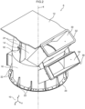
- FIG 1 it is schematically depicted a cooling rotating interface 2.
- the cooling rotating interface 2 is intended to be installed between a propulsion oriented device (not shown) and a part of a vessel, for instance the hull of the vessel (not shown).
- the vessel is located above the cooling rotating interface 2 whereas the propulsion oriented device is located below the cooling rotating interface 2.
- the propulsion oriented device is pivotable relative to the vessel around an axis of rotation 4.
- the cooling rotating interface 2 is intended to lead a cold airflow from a cooler located inside the vessel into an electric motor located inside the propulsion oriented device, and to lead a warm airflow from the electric motor into the cooler.
- the cooling rotating interface 2 includes an air box 6 and an air diffuser 8.
- the air box 6 is attached to the vessel whereas the air diffuser 8 is attached to the propulsion oriented device.
- the air diffuser 8 is able to rotate, with respect to the air box 6, about the axis of rotation 4.
- the basis 10 consist of a vector X, a vector Y and a vector Z.
- the vector Z is parallel to the axis of rotation 4.
- the terms "axial”, “radial”, “tangential” and variations thereof will be understood as referring to the axis of rotation 4.
- the words “cylinder” and “cylindrical” will be understood according to their common definition, being namely that a cylindrical surface is a surface consisting of all the points on all the lines which are parallel to a given line and which pass through a fixed plane curve in a plane not parallel to the given line.
- the words “up”, “low”, “down” and variations thereof will be understood as referring to the basis 10 when the cooling rotating interface 2 is normally installed on a vessel, that is assuming that the vector Z is substantially vertically upwardly directed.
- the air box 6 includes an upper, flat plate 12 perpendicular to the vector Z.
- the air box 6 further includes an upper cylinder of revolution 14 and a lower cylinder of revolution 16.
- the cylinders 14 and 16 have a circular axial cross-section around the axis 4 and with respective diameters d 14 , d 16 .
- the diameter d 16 is strictly greater than the diameter d 14 . More specifically, the diameter d 14 is within a range 1700 mm to 1900 mm and the diameter d 16 is within a range 2500 mm to 2750 mm.
- a lower end of the cylinder 14 is linked to an upper end of the cylinder 16 by a flat, frontal surface 18 perpendicular to the vector Z.
- the upper plate 12 is linked to an upper end of the cylinder 14.
- the air box 6 On the lower end of the cylinder 16, the air box 6 includes a collar 20.
- the collar 20 extends radially outwards from the lower end of the cylinder 16.
- the air box 6 includes a plurality of, e.g. eleven (11) reinforcing ribs 22.
- the reinforcing ribs 22 are intended to strengthen the fixation of the collar 20 to the cylinder 16.
- the air box 6 further includes a plurality of, e.g. four (4) reinforcing ribs 24.
- the reinforcing ribs 24 extend radially outwards from the cylinder 14.
- the reinforcing ribs 24 extend axially between the upper plate 12 and the frontal surface 18.
- the air box 6 includes a rectangular hatch 26 arranged on the cylinder 14.
- the hatch 26 is intended to allow a technician to access, from the vessel, to the inner volume of the propulsion oriented device.
- the air box 6 further includes a hatch 28 arranged on the cylinder 16, proximate to the collar 20.
- the hatch 28 intends to allow implementing a maintenance of a seal ring installed proximate to the collar 20, such as an air diffuser - steering top cover oil dynamic seal.
- the air box 6 further includes an upper duct 30 with an upper port 32, and a lower duct 34 with a lower port 36.
- the ducts 30 and 34 are intended to be fluidly connected, via the respective ports 32 and 36, with flexible tubes of a cooling system of the propulsion oriented device. More specifically, the upper duct 30 is intended to be connected to a flexible tube fluidly connected to an outlet of a cooler (not depicted) of the cooling system, whereas the lower duct 34 is intended to be fluidly connected to a flexible tube fluidly connected to the inlet of the cooler.
- An airflow generator such as a fan (not depicted), is mounted on one of these flexible tubes.
- the air diffuser 8 includes a main portion 38 and a peripheral portion 40.
- the peripheral portion 40 radially surrounds the main portion 38. More specifically, the radial location of the peripheral portion 40 is outwards from the radial location of the cylinder 16 of the air box 6, and the axial location of the peripheral portion 40 is right below the cylinder 16.
- the main portion 38 is located radially inside the cylinder 16.
- the main portion 38 includes a top end 39 axially located right below the cylinder 14.
- the cylinder 14 includes a seal 41 and/or a labyrinth seal (not depicted) implementing a dynamic sealing between the cylinder 14 and the top end 39.
- the main portion 38 includes an upper cylinder of revolution 42 and a lower truncated cone 44.
- the axis of revolution of the cylinder 42 and the axis of revolution of the truncated cone 44 are the same as the axis of rotation 4.
- the angle ⁇ of the truncated cone 44 with reference to the direction of the vector Z is within 25° and 30°.
- the axial cross-section of the cylinder 42 is circular around the axis of rotation 4 and has a diameter d 42 equal to the diameter d 14 .
- the truncated cone 44 includes an upper end 46 and a lower end 48.
- the truncated cone 44 is joined to the cylinder 42 by its upper end 46.
- the ends 46 and 48 are two circles around the axis of rotation 4, having respective diameters d 46 and d 48 .
- the diameter d 46 equals the diameter d 42 .
- the diameter d 48 is strictly larger than the diameter d 46 . In the depicted embodiments, the diameter d 48 is within a range 2150 mm to 2350 mm.
- the main portion 38 is a solid of revolution around the axis of rotation 4.
- the main portion 38 delimits a first fluid path, being inside the cylinder 42 and the cone 44, for the cold airflow delivered by the upper duct 30, from a second fluid path, being between the cylinder 42 and the cylinder 16, for the warm fluid flow collected by the lower duct 34.
- the main portion 38 includes a radial protrusion 50 extending radially inwards from the truncated cone 44, at its lower end 48.
- the main portion includes a plurality of, e.g. ten (10) reinforcing ribs 52 which strengthen the fixation of the protrusion 50 to the truncated cone 44.
- the protrusion 50 intends to allow the fixation of a static seal ring (not depicted) located inside the inner volume of the propulsion oriented device.
- the peripheral portion 40 includes a crown 62 extending radially outwards from the cylinder 54.
- the crown 62 includes a plurality of through bores 64 intended to allow the fixation of the air diffuser 8 to a part, e.g. a steering end cover of the propulsion oriented device.
- the peripheral portion 40 includes an upper collar 66 extending radially inwards from the cylinder 54 at its upper end 58.
- the upper collar 66 includes a radial inner edge 68 having the shape of a circle around the axis of rotation 4 and with a diameter d 68 .
- the diameter d 68 is within a range 2350 mm to 2550 mm.
- the peripheral portion 40 includes a cylindrical protrusion 70 extending axially upwards from the edge 68.
- the collar 20, the collar 66 and the cylindrical protrusion 70 allow the fixation of a dynamic seal arrangement between a steering top cover and the air diffuser 8.
- the air diffuser 8 further includes a plurality of, e.g. ten (10) attaching ribs 72.
- the attaching ribs 72 extend radially outwards from the lower end of the cylinder 42 and from the truncated cone 44.
- the attaching ribs 72 extend radially inwards from the cylinder 54 and axially downwards from the upper collar 66. Hence, the attaching ribs 72 allow attaching the main portion 38 and the peripheral portion 40.
- the attaching ribs 72 are regularly spread over the circumference of the truncated cone 44. Hence, the angle ⁇ between two adjacent ribs 72 is within a range to 30° to 50°. In the depicted embodiment, the angle between two adjacent ribs 72 is 36°.
- the ribs 72 have a thickness within a range 12 mm to 20 mm, and more specifically a thickness being equal to 16 mm.
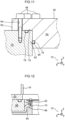
- a dynamic seal arrangement 86 is depicted between a steering top cover 88 and the air diffuser 8.
- the top cover 88 may be attached to a static part of the steering arrangement and the air box 6 may be attached to the top cover 88.
- the seal arrangement 86 may include a first lip seal 90 and a second lip seal 92 attached to the cylindrical protrusion 70. Using two lip seals for implementing dynamic sealing between the cylindrical protrusion 70 and the top cover 88 allows improving the sealing effect relative to the air flow passing through the cooling rotating interface, and relative to oil lubricating inside the steering arrangement.
- the main portion 38 is right below the cylinder 14.
- the main portion 38 is able to seal the first fluid path and the second fluid path from each other. Because the main portion 38 is a solid of revolution, the pressure drop in the first fluid path and in the second fluid path remain the same regardless of the angular orientation of the propulsion oriented device. Furthermore, due to the small thickness of the attaching ribs 52, the perturbations to the warm airflow circulating through the second fluid path are little.
Landscapes
- Engineering & Computer Science (AREA)
- Chemical & Material Sciences (AREA)
- Combustion & Propulsion (AREA)
- Mechanical Engineering (AREA)
- Ocean & Marine Engineering (AREA)
- Power Engineering (AREA)
- Structures Of Non-Positive Displacement Pumps (AREA)
- Motor Or Generator Cooling System (AREA)
Claims (12)
- Kühlende rotierende Schnittstelle (2) für eine antriebsorientierte Vorrichtung, die im Verhältnis zu einem Behälter um eine Rotationsachse (4) schwenkbar ist, wobei die kühlende rotierende Schnittstelle (2) einen Luftkasten (6), der am Behälter befestigt werden soll, und einen Luftverteiler (8) enthält, der an der antriebsorientierten Vorrichtung befestigt werden soll, sowie einen Hauptabschnitt (38) enthält, der ein um die Rotationsachse (4) Rotationskörper ist, dadurch gekennzeichnet, dass der Luftkasten (6) Folgendes umfasst:- einen oberen Rotationszylinder (14) und einen unteren Rotationszylinder (16), die jeweils einen kreisförmigen axialen Querschnitt um die Rotationsachse (4) aufweisen, wobei der Durchmesser (d16) des unteren Rotationszylinders (16) strikt größer ist als der Durchmesser (d14) des oberen Rotationszylinders (14), und- einen oberen Kanal (30) und einen unteren Kanal (34), dadurch, dass der Luftverteiler (8) Folgendes umfasst:- einen Umfangsabschnitt (40), der den Hauptabschnitt (38) umgibt und sich vom unteren Zylinder (16) radial nach außen befindet und sich axial direkt unterhalb des unteren Zylinders (16) befindet, wobei sich der Hauptabschnitt (38) radial innerhalb des unteren Zylinders (16) befindet und einen inneren Rotationszylinder (42), der kreisförmig um die Rotationsachse (4) verläuft und einen Durchmesser (d42) aufweist, der dem Durchmesser des oberen Rotationszylinders (14) gleich ist, und einen Kegelstumpf (44) umfasst, der ein erstes kreisförmiges Ende (46) und ein zweites kreisförmiges Ende (48) aufweist, wobei das zweite kreisförmige Ende (48) einen größeren Durchmesser als das erste kreisförmige Ende (48) aufweist, wobei das erste kreisförmige Ende (46) vorzugsweise näher am Behälter liegen soll als das zweite kreisförmige Ende (48), und dadurch, dass der Hauptabschnitt (38) einen ersten Fluidpfad innerhalb des inneren Rotationszylinders (42) und des Kegelstumpfes (44) durch den oberen Zylinder (14) und den oberen Kanal (30) und einen zweiten Fluidpfad zwischen dem inneren Rotationszylinder (42) und dem unteren Rotationszylinder (16) durch den unteren Kanal (34) begrenzt.
- Kühlende rotierende Schnittstelle (2) nach Anspruch 1, wobei der innere Zylinder (42) einen kreisförmigen axialen Querschnitt aufweist, wobei der Luftkasten (6) einen kreisförmigen axialen Querschnitt aufweist, wobei der axiale Querschnitt des Luftkastens (6) einen Durchmesser aufweist, der einem Durchmesser des axialen Querschnitts des inneren Zylinders (42) ist, multipliziert mit einem Faktor im Bereich von 1,3 bis 1,5.
- Kühlende rotierende Schnittstelle (2) nach Anspruch 1 oder 2, wobei der Kegelstumpf (44) des Luftverteilers (8) einen inneren Vorsprung (50) enthält, der sich vom zweiten kreisförmigen Ende (48) radial nach innen erstreckt.
- Kühlende rotierende Schnittstelle (2) nach einem der vorhergehenden Ansprüche, wobei der Luftverteiler (8) ferner einen Umfangsabschnitt (40) enthält, der den Hauptabschnitt (38) radial umgibt und einen äußeren Rotationszylinder (54) enthält, der sich in Bezug auf die Rotationsachse vom Luftkasten (6) radial nach außen befinden soll.
- Kühlende rotierende Schnittstelle (2) nach Anspruch 4, wobei der äußere Zylinder (54) einen kreisförmigen axialen Querschnitt aufweist, wobei ein Durchmesser des äußeren Zylinders (54) gleich einem Durchmesser des axialen Querschnitts des zweiten kreisförmigen Endes (48) ist, multipliziert mit einem Faktor im Bereich von 1,2 bis 1,6.
- Kühlende rotierende Schnittstelle (2) nach Anspruch 4 oder 5, wobei der Luftverteiler (8) ferner eine Vielzahl von sich radial erstreckenden Verbindungsteilen (72) enthält, die den Umfangsabschnitt (40) am Hauptabschnitt (38) befestigen.
- Kühlende rotierende Schnittstelle (2) nach Anspruch 6, wobei die Verbindungsteile (72) entlang der tangentialen Richtung eine Dicke im Bereich von 10 mm bis 30 mm, und vorzugsweise im Bereich von 12 mm bis 20 mm, aufweisen.
- Kühlende rotierende Schnittstelle (2) nach Anspruch 6 oder 7, wobei die Verbindungsteile (72) regelmäßig über den Umfang des Hauptabschnitts (38) verteilt sind, so dass der Winkel (β) zwischen zwei benachbarten Verbindungsteilen (72) aus der Vielzahl von Verbindungsteilen (72) zwischen 30° und 50° beträgt.
- Kühlende rotierende Schnittstelle (2) nach einem der Ansprüche 5 bis 8, wobei der Umfangsabschnitt (40) eine Krone (62) enthält, die vom äußeren Zylinder (54) radial nach außen vorsteht.
- Kühlende rotierende Schnittstelle (2) nach Anspruch 9, wobei der Luftverteiler (8) ferner mindestens einen statischen Dichtungsring enthält, ausgewählt aus einem ersten statischen Dichtungsring (78), der in axialem Kontakt mit der Krone (62) steht, und einem zweiten statischen Dichtungsring (80), der in radialem Kontakt mit dem äußeren Zylinder (54) steht.
- Kühlende rotierende Schnittstelle (2) nach einem der Ansprüche 5 bis 10, wobei der Umfangsabschnitt (40) einen ersten Kragen (66) enthält, der sich von einem ersten Ende (58) des äußeren Zylinders (54) radial nach innen erstreckt, wobei das erste Ende (58) in der Nähe des Behälters liegen soll, wobei der Umfangsabschnitt (40) einen zylindrischen Vorsprung (70) enthält, der sich axial von einer Innenkante (68) des ersten Kragens (66) und auf einer Seite des ersten Kragens (66) gegenüber der Seite erstreckt, an der sich der äußere Zylinder (54) befindet.
- Kühlende rotierende Schnittstelle (2) nach einem der vorhergehenden Ansprüche, wobei der Luftkasten (6) ein zum Hauptabschnitt (38) koaxiales Rotationsteil enthält, wobei die kühlende rotierende Schnittstelle (2) eine Labyrinthdichtung (90) enthält, die sich axial zwischen dem Luftverteiler (8) und dem Rotationsteil befindet.
Priority Applications (5)
| Application Number | Priority Date | Filing Date | Title |
|---|---|---|---|
| EP20306408.4A EP4001092B1 (de) | 2020-11-19 | 2020-11-19 | Kühlende drehoberfläche eines antriebsorientierten geräts |
| KR1020237017145A KR102889107B1 (ko) | 2020-11-19 | 2021-10-14 | 추진 지향 장치의 냉각 회전 인터페이스에 설치되도록 의도된 공기 디퓨저 |
| PCT/IB2021/059446 WO2022106926A1 (en) | 2020-11-19 | 2021-10-14 | Air diffuser intended to be installed in a cooling rotating interface of a propulsion oriented device |
| US18/037,605 US20230415877A1 (en) | 2020-11-19 | 2021-10-14 | Air diffuser intended to be installed in a cooling rotating interface of a propulsion oriented device |
| CN202180091166.7A CN116802116A (zh) | 2020-11-19 | 2021-10-14 | 旨在安装在推进导向装置的冷却旋转接口中的空气扩散器 |
Applications Claiming Priority (1)
| Application Number | Priority Date | Filing Date | Title |
|---|---|---|---|
| EP20306408.4A EP4001092B1 (de) | 2020-11-19 | 2020-11-19 | Kühlende drehoberfläche eines antriebsorientierten geräts |
Publications (3)
| Publication Number | Publication Date |
|---|---|
| EP4001092A1 EP4001092A1 (de) | 2022-05-25 |
| EP4001092B1 true EP4001092B1 (de) | 2025-03-05 |
| EP4001092C0 EP4001092C0 (de) | 2026-05-06 |
Family
ID=73654738
Family Applications (1)
| Application Number | Title | Priority Date | Filing Date |
|---|---|---|---|
| EP20306408.4A Active EP4001092B1 (de) | 2020-11-19 | 2020-11-19 | Kühlende drehoberfläche eines antriebsorientierten geräts |
Country Status (5)
| Country | Link |
|---|---|
| US (1) | US20230415877A1 (de) |
| EP (1) | EP4001092B1 (de) |
| KR (1) | KR102889107B1 (de) |
| CN (1) | CN116802116A (de) |
| WO (1) | WO2022106926A1 (de) |
Families Citing this family (1)
| Publication number | Priority date | Publication date | Assignee | Title |
|---|---|---|---|---|
| USD1106428S1 (en) * | 2022-09-30 | 2025-12-16 | Fm Partec S.P.A. | Air diffuser |
Family Cites Families (4)
| Publication number | Priority date | Publication date | Assignee | Title |
|---|---|---|---|---|
| FI96590C (fi) * | 1992-09-28 | 2003-11-27 | Abb Oy | Laivan propulsiolaite |
| SE517976C2 (sv) * | 2000-04-27 | 2002-08-13 | Rolls Royce Ab | Arrangemang vid podenhet |
| EP2944561B1 (de) * | 2014-05-13 | 2017-01-11 | ABB Oy | Kühlanordnung für eine Antriebseinheit |
| EP2949574B1 (de) * | 2014-05-30 | 2018-07-11 | ABB Schweiz AG | Pod-Antriebseinheit eines Schiffs |
-
2020
- 2020-11-19 EP EP20306408.4A patent/EP4001092B1/de active Active
-
2021
- 2021-10-14 US US18/037,605 patent/US20230415877A1/en active Pending
- 2021-10-14 CN CN202180091166.7A patent/CN116802116A/zh active Pending
- 2021-10-14 KR KR1020237017145A patent/KR102889107B1/ko active Active
- 2021-10-14 WO PCT/IB2021/059446 patent/WO2022106926A1/en not_active Ceased
Also Published As
| Publication number | Publication date |
|---|---|
| KR102889107B1 (ko) | 2025-11-19 |
| EP4001092C0 (de) | 2026-05-06 |
| EP4001092A1 (de) | 2022-05-25 |
| WO2022106926A1 (en) | 2022-05-27 |
| US20230415877A1 (en) | 2023-12-28 |
| KR20230107590A (ko) | 2023-07-17 |
| CN116802116A (zh) | 2023-09-22 |
Similar Documents
| Publication | Publication Date | Title |
|---|---|---|
| US7922466B2 (en) | Radial fan | |
| EP1066451B1 (de) | Deflektor zum gerichteten einleiten von leckluft in den gasstrom einer gasturbine | |
| CN108368852B (zh) | 涡轮发动机或航空器的电动离心式压缩机 | |
| EP2492513B1 (de) | Ventilator eines klimaanlagensystems | |
| US20180245598A1 (en) | Turbo Fan | |
| KR20100116672A (ko) | 가스 터빈 | |
| EP3312402B1 (de) | Rückseitenkühlstruktur eines flügelrades und auflader | |
| JP5964378B2 (ja) | 過給機 | |
| KR101848717B1 (ko) | 송풍 장치 | |
| US20230415877A1 (en) | Air diffuser intended to be installed in a cooling rotating interface of a propulsion oriented device | |
| CN110872982B (zh) | 机动车的风扇罩 | |
| CN109217535B (zh) | 电机端盖及具有其的电机 | |
| US10605234B2 (en) | Wind turbine with a nacelle including a water draining device | |
| US9914542B2 (en) | Ram air fan housing | |
| US11821370B2 (en) | Cooling system for tail cone mounted generator | |
| RU2814871C1 (ru) | Воздушный диффузор, предназначенный для установки на вращающемся модуле сопряжения системы охлаждения ориентируемого движительного устройства | |
| SE527867C2 (sv) | Kylanordning | |
| US20200007008A1 (en) | Motor with Inner Fan | |
| JP2025043963A (ja) | 回転機械の軸受装置 | |
| US6074181A (en) | Shroud for fan motor cooling | |
| US5509830A (en) | Marine propulsor cooling and lubricating system | |
| CN113028502A (zh) | 一种风扇及通风设备 | |
| CN223794364U (zh) | 一种具有内外多层扇叶结构的散热风扇 | |
| CN117028322B (zh) | 混流风机以及装配有该混流风机的油烟机 | |
| CN113531876A (zh) | 换热组件和空气调节系统 |
Legal Events
| Date | Code | Title | Description |
|---|---|---|---|
| PUAI | Public reference made under article 153(3) epc to a published international application that has entered the european phase |
Free format text: ORIGINAL CODE: 0009012 |
|
| STAA | Information on the status of an ep patent application or granted ep patent |
Free format text: STATUS: THE APPLICATION HAS BEEN PUBLISHED |
|
| AK | Designated contracting states |
Kind code of ref document: A1 Designated state(s): AL AT BE BG CH CY CZ DE DK EE ES FI FR GB GR HR HU IE IS IT LI LT LU LV MC MK MT NL NO PL PT RO RS SE SI SK SM TR |
|
| STAA | Information on the status of an ep patent application or granted ep patent |
Free format text: STATUS: REQUEST FOR EXAMINATION WAS MADE |
|
| 17P | Request for examination filed |
Effective date: 20221104 |
|
| RBV | Designated contracting states (corrected) |
Designated state(s): AL AT BE BG CH CY CZ DE DK EE ES FI FR GB GR HR HU IE IS IT LI LT LU LV MC MK MT NL NO PL PT RO RS SE SI SK SM TR |
|
| RIC1 | Information provided on ipc code assigned before grant |
Ipc: H02K 9/04 20060101ALI20240420BHEP Ipc: H02K 5/20 20060101ALI20240420BHEP Ipc: B63H 5/125 20060101ALI20240420BHEP Ipc: H02K 9/12 20060101ALI20240420BHEP Ipc: B63J 2/12 20060101AFI20240420BHEP |
|
| GRAP | Despatch of communication of intention to grant a patent |
Free format text: ORIGINAL CODE: EPIDOSNIGR1 |
|
| STAA | Information on the status of an ep patent application or granted ep patent |
Free format text: STATUS: GRANT OF PATENT IS INTENDED |
|
| INTG | Intention to grant announced |
Effective date: 20240710 |
|
| GRAS | Grant fee paid |
Free format text: ORIGINAL CODE: EPIDOSNIGR3 |
|
| GRAA | (expected) grant |
Free format text: ORIGINAL CODE: 0009210 |
|
| STAA | Information on the status of an ep patent application or granted ep patent |
Free format text: STATUS: THE PATENT HAS BEEN GRANTED |
|
| AK | Designated contracting states |
Kind code of ref document: B1 Designated state(s): AL AT BE BG CH CY CZ DE DK EE ES FI FR GB GR HR HU IE IS IT LI LT LU LV MC MK MT NL NO PL PT RO RS SE SI SK SM TR |
|
| REG | Reference to a national code |
Ref country code: GB Ref legal event code: FG4D |
|
| REG | Reference to a national code |
Ref country code: CH Ref legal event code: EP |
|
| REG | Reference to a national code |
Ref country code: IE Ref legal event code: FG4D |
|
| REG | Reference to a national code |
Ref country code: DE Ref legal event code: R096 Ref document number: 602020047136 Country of ref document: DE |
|
| U01 | Request for unitary effect filed |
Effective date: 20250402 |
|
| U07 | Unitary effect registered |
Designated state(s): AT BE BG DE DK EE FI FR IT LT LU LV MT NL PT RO SE SI Effective date: 20250410 |
|
| PG25 | Lapsed in a contracting state [announced via postgrant information from national office to epo] |
Ref country code: RS Free format text: LAPSE BECAUSE OF FAILURE TO SUBMIT A TRANSLATION OF THE DESCRIPTION OR TO PAY THE FEE WITHIN THE PRESCRIBED TIME-LIMIT Effective date: 20250605 |
|
| PG25 | Lapsed in a contracting state [announced via postgrant information from national office to epo] |
Ref country code: ES Free format text: LAPSE BECAUSE OF FAILURE TO SUBMIT A TRANSLATION OF THE DESCRIPTION OR TO PAY THE FEE WITHIN THE PRESCRIBED TIME-LIMIT Effective date: 20250305 |
|
| PG25 | Lapsed in a contracting state [announced via postgrant information from national office to epo] |
Ref country code: NO Free format text: LAPSE BECAUSE OF FAILURE TO SUBMIT A TRANSLATION OF THE DESCRIPTION OR TO PAY THE FEE WITHIN THE PRESCRIBED TIME-LIMIT Effective date: 20250605 |
|
| PG25 | Lapsed in a contracting state [announced via postgrant information from national office to epo] |
Ref country code: HR Free format text: LAPSE BECAUSE OF FAILURE TO SUBMIT A TRANSLATION OF THE DESCRIPTION OR TO PAY THE FEE WITHIN THE PRESCRIBED TIME-LIMIT Effective date: 20250305 |
|
| PG25 | Lapsed in a contracting state [announced via postgrant information from national office to epo] |
Ref country code: GR Free format text: LAPSE BECAUSE OF FAILURE TO SUBMIT A TRANSLATION OF THE DESCRIPTION OR TO PAY THE FEE WITHIN THE PRESCRIBED TIME-LIMIT Effective date: 20250606 |
|
| PG25 | Lapsed in a contracting state [announced via postgrant information from national office to epo] |
Ref country code: SM Free format text: LAPSE BECAUSE OF FAILURE TO SUBMIT A TRANSLATION OF THE DESCRIPTION OR TO PAY THE FEE WITHIN THE PRESCRIBED TIME-LIMIT Effective date: 20250305 |
|
| PG25 | Lapsed in a contracting state [announced via postgrant information from national office to epo] |
Ref country code: PL Free format text: LAPSE BECAUSE OF FAILURE TO SUBMIT A TRANSLATION OF THE DESCRIPTION OR TO PAY THE FEE WITHIN THE PRESCRIBED TIME-LIMIT Effective date: 20250305 |
|
| PG25 | Lapsed in a contracting state [announced via postgrant information from national office to epo] |
Ref country code: CZ Free format text: LAPSE BECAUSE OF FAILURE TO SUBMIT A TRANSLATION OF THE DESCRIPTION OR TO PAY THE FEE WITHIN THE PRESCRIBED TIME-LIMIT Effective date: 20250305 |
|
| PG25 | Lapsed in a contracting state [announced via postgrant information from national office to epo] |
Ref country code: SK Free format text: LAPSE BECAUSE OF FAILURE TO SUBMIT A TRANSLATION OF THE DESCRIPTION OR TO PAY THE FEE WITHIN THE PRESCRIBED TIME-LIMIT Effective date: 20250305 |
|
| PG25 | Lapsed in a contracting state [announced via postgrant information from national office to epo] |
Ref country code: IS Free format text: LAPSE BECAUSE OF FAILURE TO SUBMIT A TRANSLATION OF THE DESCRIPTION OR TO PAY THE FEE WITHIN THE PRESCRIBED TIME-LIMIT Effective date: 20250705 |
|
| U20 | Renewal fee for the european patent with unitary effect paid |
Year of fee payment: 6 Effective date: 20251028 |
|
| REG | Reference to a national code |
Ref country code: DE Ref legal event code: R097 Ref document number: 602020047136 Country of ref document: DE |
|
| PGFP | Annual fee paid to national office [announced via postgrant information from national office to epo] |
Ref country code: GB Payment date: 20251126 Year of fee payment: 6 |
|
| PLBE | No opposition filed within time limit |
Free format text: ORIGINAL CODE: 0009261 |
|
| STAA | Information on the status of an ep patent application or granted ep patent |
Free format text: STATUS: NO OPPOSITION FILED WITHIN TIME LIMIT |
|
| REG | Reference to a national code |
Ref country code: CH Ref legal event code: L10 Free format text: ST27 STATUS EVENT CODE: U-0-0-L10-L00 (AS PROVIDED BY THE NATIONAL OFFICE) Effective date: 20260114 |
|
| 26N | No opposition filed |
Effective date: 20251208 |
|
| PG25 | Lapsed in a contracting state [announced via postgrant information from national office to epo] |
Ref country code: IT Free format text: LAPSE BECAUSE OF FAILURE TO SUBMIT A TRANSLATION OF THE DESCRIPTION OR TO PAY THE FEE WITHIN THE PRESCRIBED TIME-LIMIT Effective date: 20250305 |
|
| U06 | Decision on the request for unitary effect was deleted | ||
| U0A | Member states covered by unitary patent protection deleted | ||
| U16 | Date of registration of unitary effect deleted | ||
| U18 | Date of legal effect of unitary patent protection deleted |