EP4001078A1 - Battery - Google Patents
Battery Download PDFInfo
- Publication number
- EP4001078A1 EP4001078A1 EP21208761.3A EP21208761A EP4001078A1 EP 4001078 A1 EP4001078 A1 EP 4001078A1 EP 21208761 A EP21208761 A EP 21208761A EP 4001078 A1 EP4001078 A1 EP 4001078A1
- Authority
- EP
- European Patent Office
- Prior art keywords
- battery
- case
- opening
- vehicle body
- body frame
- Prior art date
- Legal status (The legal status is an assumption and is not a legal conclusion. Google has not performed a legal analysis and makes no representation as to the accuracy of the status listed.)
- Granted
Links
Images





Classifications
-
- B—PERFORMING OPERATIONS; TRANSPORTING
- B62—LAND VEHICLES FOR TRAVELLING OTHERWISE THAN ON RAILS
- B62J—CYCLE SADDLES OR SEATS; AUXILIARY DEVICES OR ACCESSORIES SPECIALLY ADAPTED TO CYCLES AND NOT OTHERWISE PROVIDED FOR, e.g. ARTICLE CARRIERS OR CYCLE PROTECTORS
- B62J43/00—Arrangements of batteries
- B62J43/10—Arrangements of batteries for propulsion
- B62J43/16—Arrangements of batteries for propulsion on motorcycles or the like
-
- B—PERFORMING OPERATIONS; TRANSPORTING
- B62—LAND VEHICLES FOR TRAVELLING OTHERWISE THAN ON RAILS
- B62K—CYCLES; CYCLE FRAMES; CYCLE STEERING DEVICES; RIDER-OPERATED TERMINAL CONTROLS SPECIALLY ADAPTED FOR CYCLES; CYCLE AXLE SUSPENSIONS; CYCLE SIDECARS, FORECARS, OR THE LIKE
- B62K2202/00—Motorised scooters
-
- B—PERFORMING OPERATIONS; TRANSPORTING
- B62—LAND VEHICLES FOR TRAVELLING OTHERWISE THAN ON RAILS
- B62K—CYCLES; CYCLE FRAMES; CYCLE STEERING DEVICES; RIDER-OPERATED TERMINAL CONTROLS SPECIALLY ADAPTED FOR CYCLES; CYCLE AXLE SUSPENSIONS; CYCLE SIDECARS, FORECARS, OR THE LIKE
- B62K2204/00—Adaptations for driving cycles by electric motor
Definitions
- the present invention relates to a battery.
- an electric straddle-type vehicle that travels on electric power has been developed.
- a scooter-type vehicle in which a battery and the like are accommodated below a seat is known (for example, see Patent Literature 1).
- a pair of left and right seat frames are provided as a vehicle body frame, and the battery is installed inside the pair of seat frames.
- a battery module and a circuit component are accommodated in a battery case, and a plurality of fixing portions on an outer surface of the battery case are screwed to the pair of seat frames via a bracket or the like.
- Patent Literature 1 JP-A-2017-081324
- Patent Literature 1 When the circuit component disclosed in Patent Literature 1 is broken, if the battery case is not detached from the vehicle body frame, a replacement operation of the circuit component inside the battery case cannot be performed. Therefore, it is troublesome for an operator to perform the replacement operation of the circuit component.
- the present invention has been made in view of the above points, and an object of the present invention is to provide a battery capable of improving workability of a replacement operation of a circuit component by an operator.
- a battery according to an aspect of the present invention is a battery to be fixed inside a vehicle body frame of an electric straddle-type vehicle, and the battery includes: a battery module to which electric power for traveling is charged; a circuit component connected to the battery module; and a battery case accommodating the battery module and the circuit component, in which the battery case is formed with an opening that exposes the circuit component to an outside, and a cover member that covers the opening is detachably attached to the battery case, and the opening is formed at a position avoiding the vehicle body frame in a side view, thereby solving the above problems.
- the circuit component when the cover member is detached from a side of the vehicle body frame, the circuit component is exposed to the outside from the opening of the battery case in the side view. Even if the battery is not detached from the vehicle body frame at the time of breakage of the circuit component, the circuit component can be replaced through the opening of the battery case by detaching the cover member from the battery case. Therefore, an operator can easily replace the circuit component, and workability of a replacement operation of the circuit component can be improved. Although a rigidity in a vicinity of the opening of the battery case is reduced, since the battery is protected from the outside by the vehicle body frame, a strong external force does not directly act on the vicinity of the opening of the battery case.
- a battery according to an aspect of the present invention is fixed inside a vehicle body frame of an electric straddle-type vehicle.
- a battery module to which electric power for traveling is charged and a circuit component connected to the battery module are accommodated in a battery case of the battery.
- the battery case is formed with an opening at a position avoiding the vehicle body frame in a side view, and the opening is covered with a cover member detachably attached to the battery case. Even if the battery is not detached from the vehicle body frame at the time of breakage of the circuit component, the circuit component exposed to the outside can be replaced from the opening of the battery case by detaching the cover member from a side of the vehicle body frame. Therefore, an operator can easily replace the circuit component, and workability of a replacement operation of the circuit component can be improved. Although a rigidity in a vicinity of the opening of the battery case is reduced, since the battery is protected from the outside by the vehicle body frame, a strong external force does not directly act on the vicinity of the opening of the battery case.
- the straddle-type vehicle is a straddle-type vehicle of a scooter type, but the straddle-type vehicle may be a straddle-type vehicle of an electric or hybrid type.
- an arrow FR indicates a vehicle front side
- an arrow RE indicates a vehicle rear side
- an arrow L indicates a vehicle left side
- an arrow R indicates a vehicle right side.
- Fig. 1 is a left side view of the straddle-type vehicle according to the present embodiment.
- a straddle-type vehicle 1 of a scooter type is formed by attaching various covers to an underbone type vehicle body frame 10 (see Fig. 2 ) as a vehicle body exterior.
- a front frame cover 21 is provided on a front side of a vehicle, and a leg shield 22 that protects legs of a rider is provided on a rear side of the front frame cover 21.
- a footboard 23 extends rearward from a lower end of the leg shield 22, and a seat frame cover 24 is provided on a rear side of the footboard 23.
- a foot rest space for the rider is formed in front of a seat 34 by the leg shield 22 and the footboard 23.
- a handle 31 is provided on an upper side of the front frame cover 21, and a front wheel 33 is rotatably supported on a lower side of the front frame cover 21 via a pair of front forks 32.
- the seat 34 is provided on an upper side of a seat frame cover 24, and a swing arm (not shown) covered by a swing arm cover 36 is provided on a lower side of the seat frame cover 24.
- a rear wheel 37 is rotatably supported at a rear portion of the swing arm, and a rear portion of the swing arm is connected to the vehicle body frame 10 via a suspension 38.
- a battery 60 (see Fig. 3 ) is accommodated below the seat 34.
- the battery 60 is provided with a fuse 94 to be cut by an overcurrent as a circuit component of a high voltage circuit (see Fig. 6 ).
- a fuse 94 to be cut by an overcurrent as a circuit component of a high voltage circuit (see Fig. 6 ).
- the fuse 94 is cut, the fuse 94 inside a battery case 61 cannot be replaced unless the battery case 61 is detached from the vehicle body frame 10. Therefore, in the battery case 61 of the present embodiment, an opening 95 for a replacement operation that exposes the fuse 94 is formed (see Fig. 10 ).
- a service plug that cuts off the high voltage circuit must be provided in the battery, but in the present embodiment, the high voltage circuit can be cut off by detaching the fuse 94 instead of the service plug.
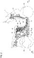
- Fig. 2 is a right side view of the vehicle body frame and an electric device according to the present embodiment.
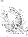
- Fig. 3 is a perspective view of the vehicle body frame and the battery according to the present embodiment as viewed from a right front side.
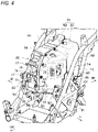
- Fig. 4 is a perspective view of the vehicle body frame and the battery according to the present embodiment as viewed from a left front side.
- Figs. 3 and 4 show a state in which the electric device other than the battery is detached from the vehicle body frame.
- a head pipe 11 into which a steering shaft (not shown) is inserted is provided in a front portion of the vehicle body frame 10.
- a front frame 12 extends downward from the head pipe 11, and a pair of lower frames 13 extend rearward from a lower portion of the front frame 12.
- a pair of seat frames (upper side frames) 14 rise obliquely rearward from substantially middle portions of the pair of lower frames 13, and a pair of support frames (lower side frames) 15 rise obliquely rearward from rear portions of the pair of lower frames 13.
- Rear portions of the pair of support frames 15 are connected to rear portions of the pair of seat frames 14 from below.
- An accommodation space of the battery 60 is formed between the pair of seat frames 14 and the pair of support frames 15, that is, inside the seat frame cover 24.
- a charger 41 that converts power source power into DC power having a predetermined voltage
- the battery 60 that is charged with the DC power from the charger 41
- a DC-DC converter 42 that steps down a voltage of the DC power are installed on an upper side of an installation space.
- a motor 43 that is driven by AC power is installed in a lower portion of the installation space.
- An inverter 44 that converts the DC power into AC power is installed in front of the motor 43, and the motor 43 is connected to the battery 60 via the inverter 44.
- the pair of seat frames 14 and the pair of support frames 15 are connected to each other in a front-rear direction via a pair of pivot brackets 16.
- the swing arm (not shown) is connected to the pair of pivot brackets 16 so as to be swingable in an upper-lower direction, and the swing arm cover 36 is attached to the swing arm as described above.
- a sprocket (not shown) and a chain (not shown) of the motor 43 are covered by the swing arm cover 36. Electric power of the battery 60 is supplied to the motor 43, and a drive force is output from the motor 43 to the rear wheel 37 via the sprocket and the chain.
- the accommodation space of the battery 60 is formed below the seat 34 (see Fig. 1 ) between the pair of seat frames 14 and the pair of support frames 15.
- a pair of holder plates 51 are provided on the seat frames 14, and a front side bridge 52 extending in a vehicle width direction is fixed to the pair of holder plates 51.
- the pair of seat frames 14 are connected via the pair of holder plates 51 and the front side bridge 52.
- the battery 60 is attached to an upper side of the front side bridge 52, and the motor 43 (see Fig. 2 ) is attached to a lower side of the front side bridge 52.
- a pair of holder brackets 53 are provided at both ends of the front side bridge 52, and the pair of holder brackets 53 are fixed to the pair of holder plates 51.
- the pair of holder plates 51 protrude forward than the pair of seat frames 14, and the pair of holder brackets 53 protrude forward than the pair of holder plates 51.
- the front side bridge 52 is positioned forward than the seat frame 14 by the pair of holder brackets 53 and the pair of holder plates 51.
- the front side bridge 52 is curved forward from the pair of holder brackets 53 on an outer side in the vehicle width direction toward an inner side in the vehicle width direction so as not to interfere with a lower front side of the battery 60.
- the front side bridge 52 is provided with a pair of battery brackets 54 and a pair of motor brackets 55 spaced apart in the vehicle width direction.
- the pair of battery brackets 54 protrude upward from the front side bridge 52 to support the battery 60 from below, and the pair of motor brackets 55 protrude downward from the front side bridge 52 to support the motor 43 from above.
- Base end portions of the brackets 54, 55 are joined to a surface of the front side bridge 52, and tip end portions of the brackets 54, 55 have mounting holes for screwing.
- the pair of battery brackets 54 support the battery 60 near a center of the front side bridge 52, and the pair of motor brackets 55 support the motor 43 on the outer side in the vehicle width direction of the pair of battery brackets 54.
- the pair of support frames 15 are connected via a rear side bridge 56 that extends in the vehicle width direction on a rear side of the battery 60.
- the battery case 61 of the battery 60 has a left and right split structure, and includes a case half body 62 on a left side and a case half body 63 on a right side.
- the case half body 62 on the left side is formed in a box shape with a right side opened
- the case half body 63 on the right side is formed in a box shape with a left side opened.
- the case half body 62 on the left side is positioned to a left side of the accommodation space
- the case half body 63 on the right side is positioned at a center of the accommodation space.
- a total dimension of the left and right case half bodies 62, 63 in the vehicle width direction is smaller than dimensions of the case half bodies 62, 63 in a vehicle length direction and a height direction.
- the battery 60 is mounted on the vehicle body frame 10 such that a lateral direction is oriented in the vehicle width direction.
- a front surface of the case half body 62 on the left side is inclined such that a dimension in the vehicle width direction increases from the vehicle front side toward the vehicle rear side.
- a pair of high voltage harness connectors 64 are provided on the front surface of the case half body 62 on the left side.
- a fuse cover (cover member) 65 is attached to a lower portion on a left side surface of the case half body 62 on the left side.
- a left side case fixing portion (case fixing portion) 66 is formed in the vicinity of the fuse cover 65 on the left side surface of the case half body 62, and the left side case fixing portion 66 is fixed to the support frame 15 on the left side via a left side bracket 67.
- a rear side case fixing portion 68 protrudes rearward from a rear surface of the case half body 62, and the rear side case fixing portion 68 is fixed to the rear side bridge 56.
- a seat connecting portion 72 protrudes forward from an upper portion of a front surface of the case half body 63 on the right side, and a front side case fixing portion 73 protrudes forward from a lower portion of the front surface of the case half body 63.
- a partition wall 74 that divides a space on a right side of the protruding portion 71 into an upper space and a lower space is formed in a central portion of the front surface of the case half body 63.
- a low voltage harness connector 75 is provided on a right side surface of the protruding portion 71 between the seat connecting portion 72 and the partition wall 74, and a high voltage harness connector 76 is provided on the right side surface of the protruding portion 71 between the partition wall 74 and the front side case fixing portion 73.
- a seat hinge bracket (not shown) fixed to the seat 34 is swingably supported on the seat connecting portion 72.
- the seat 34 is supported from below by the battery 60 inside the seat frame cover 24 (see Fig. 1 ) via the seat hinge bracket.
- the seat connecting portion 72 is integrally formed in the case half body 63 on the right side, a supporting rigidity of the seat connecting portion 72 with respect to a downward load from the seat 34 is increased in a state where the seat 34 is opened.
- the front side case fixing portion 73 is formed in a cylindrical shape with a mounting hole penetrating in the vehicle width direction.
- a long bolt is inserted into the mounting hole of the front side case fixing portion 73 and mounting holes of the pair of battery brackets 54, and the front side case fixing portion 73 is fixed to the pair of battery brackets 54 via the long bolt.
- a right side case fixing portion 77 protrudes rightward from a vicinity of the front side case fixing portion 73 on a right side surface of the case half body 63 on the right side, and a rear side case fixing portion 78 protrudes rightward from a vicinity of a rear end of the right side surface of the case half body 63 on the right side.
- the right side case fixing portion 77 is fixed to the holder plate 51 on the right side
- the rear side case fixing portion 78 is fixed to the rear side bridge 56.
- the front side case fixing portion 73 and the rear side case fixing portions 68, 78 fixed at portions separated in the front-rear direction of the vehicle body frame 10 are formed on an outer surface of the battery case 61.
- the front side case fixing portion 73 is fixed to the front side bridge 52
- the rear side case fixing portions 68, 78 are fixed to the rear side bridge 56
- the front side bridge 52 and the rear side bridge 56 separated in the front-rear direction of the vehicle body frame 10 are connected via the battery case 61.
- the front side bridge 52 and the rear side bridge 56 are integrated via the battery 60, and a rigidity of the vehicle body frame 10 with respect to a load in the front-rear direction is increased by a rigidity of the battery 60.
- Fig. 5 is a left side view of the case half body on the right side according to the present embodiment.
- Fig. 6 is a left side view of the battery from which the case half body on the left side is detached according to the present embodiment.
- Fig. 7 is a plan view of the battery from which the case half body on the left side is detached according to the present embodiment.
- the case half body 63 on the right side includes a right side wall 81 that is wide in the upper-lower direction and the front-rear direction, an upper wall 82 that extends in the vehicle width direction from an outer edge of the right side wall 81, a bottom wall 83, a front wall 84, and a rear wall 85.
- connector openings 86 and 87 for the harness connectors 75 and 76 which are vertically spaced apart from each other are formed in the vicinity of the front wall 84, and front side module fixing portions 88a to 88c which are vertically disposed adjacent to the connector openings 86 and 87 are formed.
- a rear side module fixing portion 88d is formed along the rear wall 85
- an upper side module fixing portion 88e is formed along the upper wall 82
- lower side module fixing portions 88f, 88g are formed along the bottom wall 83.
- the front side module fixing portions 88a to 88c that fix a front side of the battery module 90 and the rear side module fixing portion 88d that fixes a rear side of the battery module 90 are formed.
- the upper side module fixing portion 88e that fixes an upper side of the battery module 90 and the lower side module fixing portions 88f, 88g that fix a lower side of the battery module 90 are formed.
- the battery module 90 is fixed to the case half body 63 on the right side over an entire circumference, and a rigidity of the case half body 63 with respect to a load in the front-rear direction and the upper-lower direction is increased by a rigidity of the battery module 90.
- the front side module fixing portion 88a is formed on an opposite side of the seat connecting portion 72 with the front wall 84 interposed therebetween.
- the seat connecting portion 72 is reinforced by the rigidity of the battery module 90, and a rigidity of the seat connecting portion 72 with respect to a load from a seat 34 side is improved.
- the front side module fixing portion 88c is formed on an opposite side of the front side case fixing portion 73 with the front wall 84 interposed therebetween, and the rear side module fixing portion 88d is formed on an opposite side of the rear side case fixing portion 78 with the rear wall 85 interposed therebetween.
- the front side case fixing portion 73 and the rear side case fixing portion 78 are reinforced by the rigidity of the battery module 90, and a rigidity of a fixing position of the battery 60 with respect to the vehicle body frame 10 is increased.
- the battery module 90 As shown in Figs. 6 and 7 , the battery module 90, various electronic components, and various circuit components are accommodated in the battery case 61.
- the battery module 90 is formed in a box shape in which a plurality of battery cells are electrically connected and a plurality of battery cells are stacked.
- the battery module 90 is charged with electric power for traveling.
- An outer edge of the battery module 90 is formed along a peripheral wall of the case half body 63, and is formed in a stepped shape in which a rear side of a lower edge is positioned below a front side of the lower edge of the battery module 90.
- the outer edge of the battery module 90 is provided with attachment portions 91a to 91g fixed to the respective module fixing portions 88a to 88g (see Fig. 5 ).
- a right side of the battery module 90 is in contact with the right side wall 81 of the case half body 63 on the right side via a heat transfer seat (not shown).
- a left side of the battery module 90 protrudes leftward from the case half body 63, and a plate-shaped module bracket 92 is positioned on a left side of the battery module 90.
- the module bracket 92 is fixed to any number of the plurality of module fixing portions 88a to 88g (see Fig. 5 ) of the case half body 63 on the right side.
- An electronic component such as a battery control device 93 that controls the battery 60 and a relay that relays electric power, and a circuit component such as a fuse 94 to be cut by an overcurrent are attached to a left side surface of the module bracket 92.
- the battery control device 93 is provided so as to overlap an upper side of a rear portion of the battery module 90, and the fuse 94 is provided so as to overlap a lower side of the rear portion of the battery module 90.
- the fuse 94 is positioned below the battery module 90 and is positioned on a rear side of the fuse cover 65 (see Fig. 9 ).
- other electronic components and circuit components also overlap the battery module 90, and are installed inside a projection surface of a left side surface of the battery module 90. Therefore, the battery module 90, the electronic component, and the circuit component are compactly accommodated inside the battery case 61.
- the electronic component and the circuit component on the module bracket 92 are covered by the case half body 62 on the left side.
- the battery module 90 which is a heavy object
- the electronic component and the circuit component on the module bracket 92 are attached to the case half body 63 on the right side, and loads of the battery module 90, the electronic component, and the circuit component do not act on the case half body 62 on the left side. Therefore, the case half body 62 on the left side may be spaced apart from each component inside the case, and a degree of freedom in a shape of the case half body 62 on the left side is increased. It is also possible to prioritize weight reduction over a strength of the case half body 62.
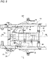
- Fig. 8 is a plan view of the vehicle body frame and the battery according to the present embodiment. Fig. 8 shows a state in which the electric device other than the battery is detached from the vehicle body frame.
- the front side case fixing portion 73 of the battery case 61 is fixed to the front side bridge 52 of the vehicle body frame 10, and the rear side case fixing portions 68, 78 of the battery case 61 are fixed to the rear side bridge 56 of the vehicle body frame 10.
- the rigidity of the vehicle body frame 10 is improved by a rigidity of the battery case 61.
- the battery module 90 is fixed inside the battery case 61 with a buffer material interposed therebetween, and the battery module 90 is not directly fixed inside the battery case 61.
- the battery module 90 is directly fixed inside the battery case 61, and the battery case 61 is supported from inside by the battery module 90, so that the rigidity of the battery case 61 itself is increased.
- a material cost does not increase for increasing a material strength of the battery case 61. Assembling the buffer material to the battery case 61 becomes unnecessary, and an assembling work is simplified.
- the case half body 63 on the right side of the battery case 61 is positioned in a center, and the battery module 90 fixed to the case half body 63 overlaps a center line L extending in a vehicle front-rear direction together with the case half body 63.
- Left and right weight balances of the straddle-type vehicle 1 are brought close to uniform, the steering stability is improved, a restoring force when the straddle-type vehicle 1 is tilted to the left or right is brought close to uniform, and a turning performance during cornering is improved.
- FIG. 9 is a left side view of the vehicle body frame and the battery according to the present embodiment.
- Fig. 10 is a left side view in which a fuse cover is detached from Fig. 9 .
- the battery case 61 is installed between the pair of seat frames 14 and the pair of support frames 15.
- the pair of seat frames 14 extend obliquely upward from the vehicle front side toward the vehicle rear side so as to pass through a center of the battery 60.
- the pair of support frames 15 extend obliquely upward from the vehicle front side toward the vehicle rear side so as to pass through a lower side of a rear portion of the battery case 61.
- the support frame 15 is connected to the seat frame 14 from a rear side of the battery case 61, and a lower side of the seat frame 14 and a lower side of the support frame 15 are connected via the pivot bracket 16.
- An opening 95 that exposes the fuse 94 (see Fig. 10 ) in the battery case 61 to the outside is formed in the battery case 61 (case half body 62).
- the opening 95 is formed at a position avoiding the vehicle body frame 10, and the opening 95 is positioned inside the seat frame 14, the support frame 15, and the pivot bracket 16.
- the opening 95 is positioned in a rear side of the pivot bracket 16 between the seat frame 14 and the support frame 15.
- the fuse cover 65 that covers the opening 95 is detachably attached to the battery case 61 by a plurality of small screws 96.
- an entry path of a tool such as a screwdriver is ensured among the seat frame 14, the support frame 15, and the pivot bracket 16.
- the small screw 96 see Fig. 9
- the fuse 94 in the battery case 61 is exposed to the outside through the opening 95.
- the fuse 94 is cut, the fuse 94 in the battery case 61 can be replaced through the opening 95.
- a work load of a replacement operation of the fuse 94 can be reduced.
- a high voltage circuit can be easily cut off by detaching the fuse 94 first. Since the fuse 94 of the battery 60 can be easily replaced, the number of components can be reduced by substituting the fuse 94 without providing a service plug in the battery 60. Since the opening 95 is formed below the battery case 61, the seat 34 is sufficiently separated from the fuse 94 to which a high voltage is applied, and a safety of the rider seated on the seat 34 is ensured.
- the fuse cover 65 (see Fig. 9 ) is mounted in the vicinity of the opening 95 of the battery case 61, a rigidity of a vicinity of the opening 95 of the battery case 61 is lower than that of other portions.
- a left side of the opening 95 of the battery case 61 is protected by the seat frame 14, the support frame 15, and the pivot bracket 16, and a strong external force does not directly act on the vicinity of the opening 95 of the battery case 61. Therefore, deformation in the vicinity of the opening 95 of the battery case 61 is prevented, and a sealing performance of the opening 95 is increased by the fuse cover 65.
- An O-ring 97 that increases the sealing performance is attached to an opening edge portion of the battery case 61.
- the opening edge portion of the battery case 61 is fixed to the support frame 15 via the left side case fixing portion 66.
- the vicinity of the opening 95 is reinforced by the left side case fixing portion 66, the deformation in the vicinity of the opening 95 of the battery case 61 is prevented, and the sealing performance of the opening 95 is increased by the fuse cover 65.
- the left side case fixing portion 66 that supports the battery case 61 is used to reinforce the vicinity of the opening 95 of the battery case 61. It is not necessary to increase a material strength in the vicinity of the opening 95 of the battery case 61 or to increase a thickness in the vicinity of the opening 95 of the battery case 61, and a cost for increasing a strength in the vicinity of the opening 95 of the battery case 61 is reduced.
- the fuse 94 is exposed to the outside from the opening 95 of the battery case 61 in the side view. Even if the battery 60 is not detached from the vehicle body frame 10 at the time of cutting the fuse 94, the fuse 94 can be replaced through the opening 95 of the battery case 61 by detaching the fuse cover 65 from the battery case 61. Therefore, an operator can easily replace the fuse 94, and workability of the replacement operation of the fuse 94 can be improved. Although the rigidity in the vicinity of the opening 95 of the battery case 61 is reduced, since the battery 60 is protected from the outside by the vehicle body frame 10, a strong external force does not directly act on the vicinity of the opening 95 of the battery case 61.
- the battery of the present embodiment is not limited to the straddle-type vehicle of the scooter type, and may be adopted in other types of straddle-type vehicles.
- the straddle-type vehicle is not limited to a motorcycle, and may be a vehicle in which a battery is installed below the seat.
- the battery module is formed in a box shape, but the battery module is not particularly limited as long as the battery module has a shape capable of holding a plurality of battery cells.
- the case half body on the left side is formed in a box shape, but the case half body on the left side may be formed in a flat plate shape.
- the battery module is fixed to the case half body on the right side, but the battery module may be fixed to the case half body on the left side.
- the case half body on the right side is positioned to a right side of the accommodation space
- the case half body on the left side is positioned at a center of the accommodation space.
- the battery case is formed with the opening that exposes the fuse, but the battery case may be formed with an opening that exposes other circuit components such as a relay and a current sensor.
- the left side case fixing portion is provided at the opening edge portion of the battery case, but the case fixing portion may not be provided at the opening edge portion of the battery case.
- the vehicle body frame includes a pair of seat frames and a pair of support frames, but the vehicle body frame may have at least a pair of seat frames.
- the battery is fixed to the vehicle body frame, but a battery holder may be fixed to the vehicle body frame, and the battery may be detachably attached to the battery holder.
- the battery (60) of the present embodiment is a battery fixed inside the vehicle body frame (10) of the electric straddle-type vehicle (1), and the battery includes: the battery module (90) to which electric power for traveling is charged; the circuit component (fuse 94) connected to the battery module; and the battery case (61) accommodating the battery module and the circuit component, in which the opening (95) that exposes the circuit component to the outside is formed in the battery case, and the cover member (fuse cover 65) that covers the opening is detachably attached to the battery case, and the opening is formed at the position avoiding the vehicle body frame in the side view.
- the circuit component when the cover member is detached from the side of the vehicle body frame, the circuit component is exposed to the outside from the opening of the battery case in the side view. Even if the battery is not detached from the vehicle body frame at the time of the breakage of the circuit component, the circuit component can be replaced through the opening of the battery case by detaching the cover member from the battery case. Therefore, the operator can easily replace the circuit component, and the workability of the replacement operation of the circuit component can be improved. Although the rigidity in the vicinity of the opening of the battery case is reduced, since the battery is protected from the outside by the vehicle body frame, the strong external force does not directly act on the vicinity of the opening of the battery case.
- the vehicle body frame includes the upper side frame (seat frame 14) and the lower side frame (support frame 15) extending at a side of the battery case, and the opening is positioned between the upper side frame and the lower side frame.
- the entry path of the tool is ensured between the upper side frame and the lower side frame, the cover member is detached using the tool, and the circuit component can be replaced through the opening of the battery case. Since the battery is protected from the outside by the upper side frame and the lower side frame, the strong external force does not directly act on the vicinity of the opening of the battery case.
- the case fixing portion (left side case fixing portion 66) fixed to the vehicle body frame is formed at an opening edge portion of the opening. According to this configuration, the rigidity in the vicinity of the opening can be increased by the case fixing portion, and deformation of the battery case can be prevented.
- the circuit component is the fuse (94) that is cut by the overcurrent. According to this configuration, even if the battery is not detached from the vehicle body frame at the time of cutting the fuse, the fuse can be replaced through the opening of the battery case. The number of components can be reduced by substituting the fuse without providing the service plug in the battery.
Landscapes
- Engineering & Computer Science (AREA)
- Mechanical Engineering (AREA)
- Automatic Cycles, And Cycles In General (AREA)
- Arrangement Or Mounting Of Propulsion Units For Vehicles (AREA)
- Battery Mounting, Suspending (AREA)
- Connection Of Batteries Or Terminals (AREA)
Abstract
Description
- The present invention relates to a battery.
- In recent years, an electric straddle-type vehicle that travels on electric power has been developed. As the electric straddle-type vehicle, a scooter-type vehicle in which a battery and the like are accommodated below a seat is known (for example, see Patent Literature 1). In the straddle-type vehicle disclosed in
Patent Literature 1, a pair of left and right seat frames are provided as a vehicle body frame, and the battery is installed inside the pair of seat frames. A battery module and a circuit component are accommodated in a battery case, and a plurality of fixing portions on an outer surface of the battery case are screwed to the pair of seat frames via a bracket or the like. - Patent Literature 1:
JP-A-2017-081324 - When the circuit component disclosed in
Patent Literature 1 is broken, if the battery case is not detached from the vehicle body frame, a replacement operation of the circuit component inside the battery case cannot be performed. Therefore, it is troublesome for an operator to perform the replacement operation of the circuit component. - The present invention has been made in view of the above points, and an object of the present invention is to provide a battery capable of improving workability of a replacement operation of a circuit component by an operator.
- A battery according to an aspect of the present invention is a battery to be fixed inside a vehicle body frame of an electric straddle-type vehicle, and the battery includes: a battery module to which electric power for traveling is charged; a circuit component connected to the battery module; and a battery case accommodating the battery module and the circuit component, in which the battery case is formed with an opening that exposes the circuit component to an outside, and a cover member that covers the opening is detachably attached to the battery case, and the opening is formed at a position avoiding the vehicle body frame in a side view, thereby solving the above problems.
- According to the battery of an aspect of the present invention, when the cover member is detached from a side of the vehicle body frame, the circuit component is exposed to the outside from the opening of the battery case in the side view. Even if the battery is not detached from the vehicle body frame at the time of breakage of the circuit component, the circuit component can be replaced through the opening of the battery case by detaching the cover member from the battery case. Therefore, an operator can easily replace the circuit component, and workability of a replacement operation of the circuit component can be improved. Although a rigidity in a vicinity of the opening of the battery case is reduced, since the battery is protected from the outside by the vehicle body frame, a strong external force does not directly act on the vicinity of the opening of the battery case.
-
- [
Fig. 1] Fig. 1 is a side view of a straddle-type vehicle according to the present embodiment. - [
Fig. 2] Fig. 2 is a right side view of a vehicle body frame and an electric device according to the present embodiment. - [
Fig. 3] Fig. 3 is a perspective view of the vehicle body frame and a battery according to the present embodiment as viewed from a right front side. - [
Fig. 4] Fig. 4 is a perspective view of the vehicle body frame and the battery according to the present embodiment as viewed from a left front side. - [
Fig. 5] Fig. 5 is a left side view of a case half body on a right side according to the present embodiment. - [
Fig. 6] Fig. 6 is a left side view of the battery from which a case half body on a left side is detached according to the present embodiment. - [
Fig. 7] Fig. 7 is a plan view of the battery from which the case half body on the left side is detached according to the present embodiment. - [
Fig. 8] Fig. 8 is a plan view of the vehicle body frame and the battery according to the present embodiment. - [
Fig. 9] Fig. 9 is a left side view of the vehicle body frame and the battery according to the present embodiment. - [
Fig. 10] Fig. 10 is a left side view in which a fuse cover is detached fromFig. 9 . - A battery according to an aspect of the present invention is fixed inside a vehicle body frame of an electric straddle-type vehicle. A battery module to which electric power for traveling is charged and a circuit component connected to the battery module are accommodated in a battery case of the battery. The battery case is formed with an opening at a position avoiding the vehicle body frame in a side view, and the opening is covered with a cover member detachably attached to the battery case. Even if the battery is not detached from the vehicle body frame at the time of breakage of the circuit component, the circuit component exposed to the outside can be replaced from the opening of the battery case by detaching the cover member from a side of the vehicle body frame. Therefore, an operator can easily replace the circuit component, and workability of a replacement operation of the circuit component can be improved. Although a rigidity in a vicinity of the opening of the battery case is reduced, since the battery is protected from the outside by the vehicle body frame, a strong external force does not directly act on the vicinity of the opening of the battery case.
- Hereinafter, the present embodiment will be described in detail with reference to the accompanying drawings. In the present embodiment, the straddle-type vehicle is a straddle-type vehicle of a scooter type, but the straddle-type vehicle may be a straddle-type vehicle of an electric or hybrid type. In addition, in the following drawings, an arrow FR indicates a vehicle front side, an arrow RE indicates a vehicle rear side, an arrow L indicates a vehicle left side, and an arrow R indicates a vehicle right side.
Fig. 1 is a left side view of the straddle-type vehicle according to the present embodiment. - As shown in
Fig. 1 , a straddle-type vehicle 1 of a scooter type is formed by attaching various covers to an underbone type vehicle body frame 10 (seeFig. 2 ) as a vehicle body exterior. Afront frame cover 21 is provided on a front side of a vehicle, and aleg shield 22 that protects legs of a rider is provided on a rear side of thefront frame cover 21. Afootboard 23 extends rearward from a lower end of theleg shield 22, and aseat frame cover 24 is provided on a rear side of thefootboard 23. A foot rest space for the rider is formed in front of aseat 34 by theleg shield 22 and thefootboard 23. - A
handle 31 is provided on an upper side of thefront frame cover 21, and afront wheel 33 is rotatably supported on a lower side of thefront frame cover 21 via a pair offront forks 32. Theseat 34 is provided on an upper side of aseat frame cover 24, and a swing arm (not shown) covered by aswing arm cover 36 is provided on a lower side of theseat frame cover 24. Arear wheel 37 is rotatably supported at a rear portion of the swing arm, and a rear portion of the swing arm is connected to thevehicle body frame 10 via asuspension 38. A battery 60 (seeFig. 3 ) is accommodated below theseat 34. - The
battery 60 is provided with afuse 94 to be cut by an overcurrent as a circuit component of a high voltage circuit (seeFig. 6 ). When thefuse 94 is cut, thefuse 94 inside abattery case 61 cannot be replaced unless thebattery case 61 is detached from thevehicle body frame 10. Therefore, in thebattery case 61 of the present embodiment, anopening 95 for a replacement operation that exposes thefuse 94 is formed (seeFig. 10 ). In general, a service plug that cuts off the high voltage circuit must be provided in the battery, but in the present embodiment, the high voltage circuit can be cut off by detaching thefuse 94 instead of the service plug. - Hereinafter, a vehicle body frame and a battery of the present embodiment will be described with reference to
Figs. 2 to 4 .Fig. 2 is a right side view of the vehicle body frame and an electric device according to the present embodiment.Fig. 3 is a perspective view of the vehicle body frame and the battery according to the present embodiment as viewed from a right front side.Fig. 4 is a perspective view of the vehicle body frame and the battery according to the present embodiment as viewed from a left front side.Figs. 3 and4 show a state in which the electric device other than the battery is detached from the vehicle body frame. - As shown in
Fig. 2 , ahead pipe 11 into which a steering shaft (not shown) is inserted is provided in a front portion of thevehicle body frame 10. Afront frame 12 extends downward from thehead pipe 11, and a pair oflower frames 13 extend rearward from a lower portion of thefront frame 12. A pair of seat frames (upper side frames) 14 rise obliquely rearward from substantially middle portions of the pair oflower frames 13, and a pair of support frames (lower side frames) 15 rise obliquely rearward from rear portions of the pair oflower frames 13. Rear portions of the pair ofsupport frames 15 are connected to rear portions of the pair ofseat frames 14 from below. - An accommodation space of the
battery 60 is formed between the pair ofseat frames 14 and the pair ofsupport frames 15, that is, inside theseat frame cover 24. Acharger 41 that converts power source power into DC power having a predetermined voltage, thebattery 60 that is charged with the DC power from thecharger 41, and a DC-DC converter 42 that steps down a voltage of the DC power are installed on an upper side of an installation space. Amotor 43 that is driven by AC power is installed in a lower portion of the installation space. Aninverter 44 that converts the DC power into AC power is installed in front of themotor 43, and themotor 43 is connected to thebattery 60 via theinverter 44. - The pair of seat frames 14 and the pair of support frames 15 are connected to each other in a front-rear direction via a pair of
pivot brackets 16. The swing arm (not shown) is connected to the pair ofpivot brackets 16 so as to be swingable in an upper-lower direction, and theswing arm cover 36 is attached to the swing arm as described above. A sprocket (not shown) and a chain (not shown) of themotor 43 are covered by theswing arm cover 36. Electric power of thebattery 60 is supplied to themotor 43, and a drive force is output from themotor 43 to therear wheel 37 via the sprocket and the chain. - As shown in
Figs. 3 and4 , the accommodation space of thebattery 60 is formed below the seat 34 (seeFig. 1 ) between the pair of seat frames 14 and the pair of support frames 15. A pair ofholder plates 51 are provided on the seat frames 14, and afront side bridge 52 extending in a vehicle width direction is fixed to the pair ofholder plates 51. The pair of seat frames 14 are connected via the pair ofholder plates 51 and thefront side bridge 52. Thebattery 60 is attached to an upper side of thefront side bridge 52, and the motor 43 (seeFig. 2 ) is attached to a lower side of thefront side bridge 52. - A pair of
holder brackets 53 are provided at both ends of thefront side bridge 52, and the pair ofholder brackets 53 are fixed to the pair ofholder plates 51. The pair ofholder plates 51 protrude forward than the pair of seat frames 14, and the pair ofholder brackets 53 protrude forward than the pair ofholder plates 51. Thefront side bridge 52 is positioned forward than theseat frame 14 by the pair ofholder brackets 53 and the pair ofholder plates 51. Thefront side bridge 52 is curved forward from the pair ofholder brackets 53 on an outer side in the vehicle width direction toward an inner side in the vehicle width direction so as not to interfere with a lower front side of thebattery 60. - The
front side bridge 52 is provided with a pair ofbattery brackets 54 and a pair ofmotor brackets 55 spaced apart in the vehicle width direction. The pair ofbattery brackets 54 protrude upward from thefront side bridge 52 to support thebattery 60 from below, and the pair ofmotor brackets 55 protrude downward from thefront side bridge 52 to support themotor 43 from above. Base end portions of thebrackets front side bridge 52, and tip end portions of thebrackets battery brackets 54 support thebattery 60 near a center of thefront side bridge 52, and the pair ofmotor brackets 55 support themotor 43 on the outer side in the vehicle width direction of the pair ofbattery brackets 54. The pair of support frames 15 are connected via arear side bridge 56 that extends in the vehicle width direction on a rear side of thebattery 60. - The
battery case 61 of thebattery 60 has a left and right split structure, and includes a casehalf body 62 on a left side and a casehalf body 63 on a right side. The casehalf body 62 on the left side is formed in a box shape with a right side opened, and the casehalf body 63 on the right side is formed in a box shape with a left side opened. The casehalf body 62 on the left side is positioned to a left side of the accommodation space, and the casehalf body 63 on the right side is positioned at a center of the accommodation space. A total dimension of the left and rightcase half bodies case half bodies battery 60 is mounted on thevehicle body frame 10 such that a lateral direction is oriented in the vehicle width direction. - A front surface of the case
half body 62 on the left side is inclined such that a dimension in the vehicle width direction increases from the vehicle front side toward the vehicle rear side. A pair of highvoltage harness connectors 64 are provided on the front surface of the casehalf body 62 on the left side. A fuse cover (cover member) 65 is attached to a lower portion on a left side surface of the casehalf body 62 on the left side. A left side case fixing portion (case fixing portion) 66 is formed in the vicinity of thefuse cover 65 on the left side surface of the casehalf body 62, and the left sidecase fixing portion 66 is fixed to thesupport frame 15 on the left side via aleft side bracket 67. A rear side case fixing portion 68 (seeFig. 8 ) protrudes rearward from a rear surface of the casehalf body 62, and the rear sidecase fixing portion 68 is fixed to therear side bridge 56. - From a front surface of the
battery 60, a vicinity of mating surfaces of the left casehalf body 62 and the rightcase half body 63 protrudes forward to form a vertically long protrudingportion 71. Aseat connecting portion 72 protrudes forward from an upper portion of a front surface of the casehalf body 63 on the right side, and a front sidecase fixing portion 73 protrudes forward from a lower portion of the front surface of the casehalf body 63. Apartition wall 74 that divides a space on a right side of the protrudingportion 71 into an upper space and a lower space is formed in a central portion of the front surface of the casehalf body 63. A lowvoltage harness connector 75 is provided on a right side surface of the protrudingportion 71 between theseat connecting portion 72 and thepartition wall 74, and a highvoltage harness connector 76 is provided on the right side surface of the protrudingportion 71 between thepartition wall 74 and the front sidecase fixing portion 73. - A seat hinge bracket (not shown) fixed to the
seat 34 is swingably supported on theseat connecting portion 72. Theseat 34 is supported from below by thebattery 60 inside the seat frame cover 24 (seeFig. 1 ) via the seat hinge bracket. When theseat 34 is opened with a front end portion of thebattery 60 as a fulcrum, thebattery 60 inside theseat frame cover 24 is exposed to the outside. Since theseat connecting portion 72 is integrally formed in the casehalf body 63 on the right side, a supporting rigidity of theseat connecting portion 72 with respect to a downward load from theseat 34 is increased in a state where theseat 34 is opened. - The front side
case fixing portion 73 is formed in a cylindrical shape with a mounting hole penetrating in the vehicle width direction. A long bolt is inserted into the mounting hole of the front sidecase fixing portion 73 and mounting holes of the pair ofbattery brackets 54, and the front sidecase fixing portion 73 is fixed to the pair ofbattery brackets 54 via the long bolt. A right sidecase fixing portion 77 protrudes rightward from a vicinity of the front sidecase fixing portion 73 on a right side surface of the casehalf body 63 on the right side, and a rear sidecase fixing portion 78 protrudes rightward from a vicinity of a rear end of the right side surface of the casehalf body 63 on the right side. The right sidecase fixing portion 77 is fixed to theholder plate 51 on the right side, and the rear sidecase fixing portion 78 is fixed to therear side bridge 56. - Thus, the front side
case fixing portion 73 and the rear sidecase fixing portions vehicle body frame 10 are formed on an outer surface of thebattery case 61. The front sidecase fixing portion 73 is fixed to thefront side bridge 52, the rear sidecase fixing portions rear side bridge 56, and thefront side bridge 52 and therear side bridge 56 separated in the front-rear direction of thevehicle body frame 10 are connected via thebattery case 61. Thefront side bridge 52 and therear side bridge 56 are integrated via thebattery 60, and a rigidity of thevehicle body frame 10 with respect to a load in the front-rear direction is increased by a rigidity of thebattery 60. - Hereinafter, a detailed configuration of the battery will be described with reference to
Figs. 5 to 7 .Fig. 5 is a left side view of the case half body on the right side according to the present embodiment.Fig. 6 is a left side view of the battery from which the case half body on the left side is detached according to the present embodiment.Fig. 7 is a plan view of the battery from which the case half body on the left side is detached according to the present embodiment. - As shown in
Fig. 5 , the casehalf body 63 on the right side includes aright side wall 81 that is wide in the upper-lower direction and the front-rear direction, anupper wall 82 that extends in the vehicle width direction from an outer edge of theright side wall 81, abottom wall 83, afront wall 84, and arear wall 85. On an inner surface of theright side wall 81,connector openings harness connectors 75 and 76 (seeFig. 6 ) which are vertically spaced apart from each other are formed in the vicinity of thefront wall 84, and front sidemodule fixing portions 88a to 88c which are vertically disposed adjacent to theconnector openings right side wall 81, a rear sidemodule fixing portion 88d is formed along therear wall 85, an upper sidemodule fixing portion 88e is formed along theupper wall 82, and lower sidemodule fixing portions bottom wall 83. - Thus, on an inner surface of the case
half body 63 on the right side, the front sidemodule fixing portions 88a to 88c that fix a front side of thebattery module 90 and the rear sidemodule fixing portion 88d that fixes a rear side of thebattery module 90 are formed. On the inner surface of the casehalf body 63, the upper sidemodule fixing portion 88e that fixes an upper side of thebattery module 90 and the lower sidemodule fixing portions battery module 90 are formed. Thebattery module 90 is fixed to the casehalf body 63 on the right side over an entire circumference, and a rigidity of the casehalf body 63 with respect to a load in the front-rear direction and the upper-lower direction is increased by a rigidity of thebattery module 90. - The front side
module fixing portion 88a is formed on an opposite side of theseat connecting portion 72 with thefront wall 84 interposed therebetween. Theseat connecting portion 72 is reinforced by the rigidity of thebattery module 90, and a rigidity of theseat connecting portion 72 with respect to a load from aseat 34 side is improved. The front sidemodule fixing portion 88c is formed on an opposite side of the front sidecase fixing portion 73 with thefront wall 84 interposed therebetween, and the rear sidemodule fixing portion 88d is formed on an opposite side of the rear sidecase fixing portion 78 with therear wall 85 interposed therebetween. The front sidecase fixing portion 73 and the rear sidecase fixing portion 78 are reinforced by the rigidity of thebattery module 90, and a rigidity of a fixing position of thebattery 60 with respect to thevehicle body frame 10 is increased. - As shown in
Figs. 6 and7 , thebattery module 90, various electronic components, and various circuit components are accommodated in thebattery case 61. Thebattery module 90 is formed in a box shape in which a plurality of battery cells are electrically connected and a plurality of battery cells are stacked. Thebattery module 90 is charged with electric power for traveling. An outer edge of thebattery module 90 is formed along a peripheral wall of the casehalf body 63, and is formed in a stepped shape in which a rear side of a lower edge is positioned below a front side of the lower edge of thebattery module 90. The outer edge of thebattery module 90 is provided withattachment portions 91a to 91g fixed to the respectivemodule fixing portions 88a to 88g (seeFig. 5 ). - A right side of the
battery module 90 is in contact with theright side wall 81 of the casehalf body 63 on the right side via a heat transfer seat (not shown). A left side of thebattery module 90 protrudes leftward from the casehalf body 63, and a plate-shapedmodule bracket 92 is positioned on a left side of thebattery module 90. Themodule bracket 92 is fixed to any number of the plurality ofmodule fixing portions 88a to 88g (seeFig. 5 ) of the casehalf body 63 on the right side. An electronic component such as abattery control device 93 that controls thebattery 60 and a relay that relays electric power, and a circuit component such as afuse 94 to be cut by an overcurrent are attached to a left side surface of themodule bracket 92. - In a side view, the
battery control device 93 is provided so as to overlap an upper side of a rear portion of thebattery module 90, and thefuse 94 is provided so as to overlap a lower side of the rear portion of thebattery module 90. Thefuse 94 is positioned below thebattery module 90 and is positioned on a rear side of the fuse cover 65 (seeFig. 9 ). In the side view, other electronic components and circuit components also overlap thebattery module 90, and are installed inside a projection surface of a left side surface of thebattery module 90. Therefore, thebattery module 90, the electronic component, and the circuit component are compactly accommodated inside thebattery case 61. - The electronic component and the circuit component on the
module bracket 92 are covered by the casehalf body 62 on the left side. At this time, thebattery module 90, which is a heavy object, the electronic component and the circuit component on themodule bracket 92 are attached to the casehalf body 63 on the right side, and loads of thebattery module 90, the electronic component, and the circuit component do not act on the casehalf body 62 on the left side. Therefore, the casehalf body 62 on the left side may be spaced apart from each component inside the case, and a degree of freedom in a shape of the casehalf body 62 on the left side is increased. It is also possible to prioritize weight reduction over a strength of the casehalf body 62. - A support structure of the battery will be described with reference to
Fig. 8. Fig. 8 is a plan view of the vehicle body frame and the battery according to the present embodiment.Fig. 8 shows a state in which the electric device other than the battery is detached from the vehicle body frame. - As shown in
Fig. 8 , the front sidecase fixing portion 73 of thebattery case 61 is fixed to thefront side bridge 52 of thevehicle body frame 10, and the rear sidecase fixing portions battery case 61 are fixed to therear side bridge 56 of thevehicle body frame 10. By connecting thefront side bridge 52 and therear side bridge 56 via thebattery case 61, the rigidity of thevehicle body frame 10 is improved by a rigidity of thebattery case 61. In order to further improve the rigidity of thevehicle body frame 10, it is necessary to increase the rigidity of thebattery case 61 itself by utilizing the rigidity of thebattery module 90 fixed inside thebattery case 61. - Usually, the
battery module 90 is fixed inside thebattery case 61 with a buffer material interposed therebetween, and thebattery module 90 is not directly fixed inside thebattery case 61. In the present embodiment, thebattery module 90 is directly fixed inside thebattery case 61, and thebattery case 61 is supported from inside by thebattery module 90, so that the rigidity of thebattery case 61 itself is increased. By utilizing the rigidity of thebattery module 90, a material cost does not increase for increasing a material strength of thebattery case 61. Assembling the buffer material to thebattery case 61 becomes unnecessary, and an assembling work is simplified. - Since the
heavy battery module 90 is accommodated inside thebattery case 61, it is necessary to balance left and right weights in order to maintain a steering stability of the straddle-type vehicle 1. Therefore, the casehalf body 63 on the right side of thebattery case 61 is positioned in a center, and thebattery module 90 fixed to the casehalf body 63 overlaps a center line L extending in a vehicle front-rear direction together with the casehalf body 63. Left and right weight balances of the straddle-type vehicle 1 are brought close to uniform, the steering stability is improved, a restoring force when the straddle-type vehicle 1 is tilted to the left or right is brought close to uniform, and a turning performance during cornering is improved. - A fuse replacement operation will be described with reference to
Figs. 9 and10 .Fig. 9 is a left side view of the vehicle body frame and the battery according to the present embodiment.Fig. 10 is a left side view in which a fuse cover is detached fromFig. 9 . - As shown in
Fig. 9 , thebattery case 61 is installed between the pair of seat frames 14 and the pair of support frames 15. In the side view, the pair of seat frames 14 extend obliquely upward from the vehicle front side toward the vehicle rear side so as to pass through a center of thebattery 60. In the side view, the pair of support frames 15 extend obliquely upward from the vehicle front side toward the vehicle rear side so as to pass through a lower side of a rear portion of thebattery case 61. Thesupport frame 15 is connected to theseat frame 14 from a rear side of thebattery case 61, and a lower side of theseat frame 14 and a lower side of thesupport frame 15 are connected via thepivot bracket 16. - An opening 95 (see
Fig. 10 ) that exposes the fuse 94 (seeFig. 10 ) in thebattery case 61 to the outside is formed in the battery case 61 (case half body 62). In the side view, theopening 95 is formed at a position avoiding thevehicle body frame 10, and theopening 95 is positioned inside theseat frame 14, thesupport frame 15, and thepivot bracket 16. Specifically, theopening 95 is positioned in a rear side of thepivot bracket 16 between theseat frame 14 and thesupport frame 15. The fuse cover 65 that covers theopening 95 is detachably attached to thebattery case 61 by a plurality ofsmall screws 96. - As shown in
Fig. 10 , an entry path of a tool such as a screwdriver is ensured among theseat frame 14, thesupport frame 15, and thepivot bracket 16. When the small screw 96 (seeFig. 9 ) of thefuse cover 65 is removed using the tool, thefuse 94 in thebattery case 61 is exposed to the outside through theopening 95. When thefuse 94 is cut, thefuse 94 in thebattery case 61 can be replaced through theopening 95. At this time, since thefuse 94 can be easily replaced in a state where thebattery case 61 is fixed to thevehicle body frame 10, a work load of a replacement operation of thefuse 94 can be reduced. - In addition to the replacement operation of the
fuse 94, when detaching the electric device such as themotor 43 or the inverter 44 (seeFig. 2 ) from thevehicle body frame 10, a high voltage circuit can be easily cut off by detaching thefuse 94 first. Since thefuse 94 of thebattery 60 can be easily replaced, the number of components can be reduced by substituting thefuse 94 without providing a service plug in thebattery 60. Since theopening 95 is formed below thebattery case 61, theseat 34 is sufficiently separated from thefuse 94 to which a high voltage is applied, and a safety of the rider seated on theseat 34 is ensured. - Although the fuse cover 65 (see
Fig. 9 ) is mounted in the vicinity of theopening 95 of thebattery case 61, a rigidity of a vicinity of theopening 95 of thebattery case 61 is lower than that of other portions. A left side of theopening 95 of thebattery case 61 is protected by theseat frame 14, thesupport frame 15, and thepivot bracket 16, and a strong external force does not directly act on the vicinity of theopening 95 of thebattery case 61. Therefore, deformation in the vicinity of theopening 95 of thebattery case 61 is prevented, and a sealing performance of theopening 95 is increased by thefuse cover 65. An O-ring 97 that increases the sealing performance is attached to an opening edge portion of thebattery case 61. - The opening edge portion of the
battery case 61 is fixed to thesupport frame 15 via the left sidecase fixing portion 66. The vicinity of theopening 95 is reinforced by the left sidecase fixing portion 66, the deformation in the vicinity of theopening 95 of thebattery case 61 is prevented, and the sealing performance of theopening 95 is increased by thefuse cover 65. The left sidecase fixing portion 66 that supports thebattery case 61 is used to reinforce the vicinity of theopening 95 of thebattery case 61. It is not necessary to increase a material strength in the vicinity of theopening 95 of thebattery case 61 or to increase a thickness in the vicinity of theopening 95 of thebattery case 61, and a cost for increasing a strength in the vicinity of theopening 95 of thebattery case 61 is reduced. - As described above, according to the present embodiment, by detaching the fuse cover 65 from a side of the
vehicle body frame 10, thefuse 94 is exposed to the outside from theopening 95 of thebattery case 61 in the side view. Even if thebattery 60 is not detached from thevehicle body frame 10 at the time of cutting thefuse 94, thefuse 94 can be replaced through theopening 95 of thebattery case 61 by detaching the fuse cover 65 from thebattery case 61. Therefore, an operator can easily replace thefuse 94, and workability of the replacement operation of thefuse 94 can be improved. Although the rigidity in the vicinity of theopening 95 of thebattery case 61 is reduced, since thebattery 60 is protected from the outside by thevehicle body frame 10, a strong external force does not directly act on the vicinity of theopening 95 of thebattery case 61. - The battery of the present embodiment is not limited to the straddle-type vehicle of the scooter type, and may be adopted in other types of straddle-type vehicles. The straddle-type vehicle is not limited to a motorcycle, and may be a vehicle in which a battery is installed below the seat.
- In the present embodiment, the battery module is formed in a box shape, but the battery module is not particularly limited as long as the battery module has a shape capable of holding a plurality of battery cells.
- In the present embodiment, the case half body on the left side is formed in a box shape, but the case half body on the left side may be formed in a flat plate shape.
- In the present embodiment, the battery module is fixed to the case half body on the right side, but the battery module may be fixed to the case half body on the left side. In this case, the case half body on the right side is positioned to a right side of the accommodation space, and the case half body on the left side is positioned at a center of the accommodation space.
- In the present embodiment, the battery case is formed with the opening that exposes the fuse, but the battery case may be formed with an opening that exposes other circuit components such as a relay and a current sensor.
- In the present embodiment, the left side case fixing portion is provided at the opening edge portion of the battery case, but the case fixing portion may not be provided at the opening edge portion of the battery case.
- In the present embodiment, the vehicle body frame includes a pair of seat frames and a pair of support frames, but the vehicle body frame may have at least a pair of seat frames.
- In the present embodiment, the battery is fixed to the vehicle body frame, but a battery holder may be fixed to the vehicle body frame, and the battery may be detachably attached to the battery holder.
- As described above, the battery (60) of the present embodiment is a battery fixed inside the vehicle body frame (10) of the electric straddle-type vehicle (1), and the battery includes: the battery module (90) to which electric power for traveling is charged; the circuit component (fuse 94) connected to the battery module; and the battery case (61) accommodating the battery module and the circuit component, in which the opening (95) that exposes the circuit component to the outside is formed in the battery case, and the cover member (fuse cover 65) that covers the opening is detachably attached to the battery case, and the opening is formed at the position avoiding the vehicle body frame in the side view. According to this configuration, when the cover member is detached from the side of the vehicle body frame, the circuit component is exposed to the outside from the opening of the battery case in the side view. Even if the battery is not detached from the vehicle body frame at the time of the breakage of the circuit component, the circuit component can be replaced through the opening of the battery case by detaching the cover member from the battery case. Therefore, the operator can easily replace the circuit component, and the workability of the replacement operation of the circuit component can be improved. Although the rigidity in the vicinity of the opening of the battery case is reduced, since the battery is protected from the outside by the vehicle body frame, the strong external force does not directly act on the vicinity of the opening of the battery case.
- In the battery of the present embodiment, the vehicle body frame includes the upper side frame (seat frame 14) and the lower side frame (support frame 15) extending at a side of the battery case, and the opening is positioned between the upper side frame and the lower side frame. According to this configuration, the entry path of the tool is ensured between the upper side frame and the lower side frame, the cover member is detached using the tool, and the circuit component can be replaced through the opening of the battery case. Since the battery is protected from the outside by the upper side frame and the lower side frame, the strong external force does not directly act on the vicinity of the opening of the battery case.
- In the battery of the present embodiment, the case fixing portion (left side case fixing portion 66) fixed to the vehicle body frame is formed at an opening edge portion of the opening. According to this configuration, the rigidity in the vicinity of the opening can be increased by the case fixing portion, and deformation of the battery case can be prevented.
- In the battery of the present embodiment, the circuit component is the fuse (94) that is cut by the overcurrent. According to this configuration, even if the battery is not detached from the vehicle body frame at the time of cutting the fuse, the fuse can be replaced through the opening of the battery case. The number of components can be reduced by substituting the fuse without providing the service plug in the battery.
- Although the present embodiment has been described, the above-described embodiment and modifications may be combined entirely or partially as another embodiment.
- The technique of the present disclosure is not limited to the above-described embodiment, and various changes, substitutions, and modifications may be made without departing from the spirit of the technical idea of the present disclosure. The present disclosure may be implemented using other methods as long as the technical concept can be implemented by the methods through advance of the technology or other derivative technology. Accordingly, the claims cover all embodiments that may be included within the scope of the technical concepts.
-
- 1:
- straddle-type vehicle
- 10:
- vehicle body frame
- 14:
- seat frame (upper side frame)
- 15:
- support frame (lower side frame)
- 60:
- battery
- 61:
- battery case
- 65:
- fuse cover
- 66:
- left side case fixing portion (case fixing portion)
- 90:
- battery module
- 94:
- fuse (circuit component)
- 95:
- opening
Claims (4)
- A battery (60), to be fixed inside a vehicle body frame (10) of an electric straddle-type vehicle (1), the battery (60) characterized by comprising:a battery module (90) to which electric power for traveling is charged;a circuit component (94) connected to the battery module (90); anda battery case (61) accommodating the battery module (90) and the circuit component (94), whereinthe battery case (61) is formed with an opening (95) that exposes the circuit component (94) to an outside, and a cover member (65) that covers the opening is detachably attached to the battery case (61), andthe opening (95) is formed at a position avoiding the vehicle body frame (10) in a side view.
- The battery (60) according to claim 1, whereinthe vehicle body frame (10) includes an upper side frame (14) and a lower side frame (15) that extend at a side of the battery case (61), andthe opening (95) is positioned between the upper side frame (14) and the lower side frame (15).
- The battery (60) according to claim 1 or 2, wherein
a case fixing portion (66) configured to be fixed to the vehicle body frame (10) is formed at an opening edge portion of the opening (95). - The battery (60) according to any one of claims 1 to 3, wherein
the circuit component (94) is a fuse configured to be cut by an overcurrent.
Applications Claiming Priority (1)
| Application Number | Priority Date | Filing Date | Title |
|---|---|---|---|
| JP2020194484A JP7600637B2 (en) | 2020-11-24 | 2020-11-24 | Battery |
Publications (2)
| Publication Number | Publication Date |
|---|---|
| EP4001078A1 true EP4001078A1 (en) | 2022-05-25 |
| EP4001078B1 EP4001078B1 (en) | 2024-01-17 |
Family
ID=78676477
Family Applications (1)
| Application Number | Title | Priority Date | Filing Date |
|---|---|---|---|
| EP21208761.3A Active EP4001078B1 (en) | 2020-11-24 | 2021-11-17 | Battery |
Country Status (2)
| Country | Link |
|---|---|
| EP (1) | EP4001078B1 (en) |
| JP (1) | JP7600637B2 (en) |
Cited By (2)
| Publication number | Priority date | Publication date | Assignee | Title |
|---|---|---|---|---|
| EP4530172A1 (en) * | 2023-09-29 | 2025-04-02 | Suzuki Motor Corporation | Battery arrangement of a straddle-type vehicle |
| EP4530167A1 (en) * | 2023-09-29 | 2025-04-02 | Suzuki Motor Corporation | Battery arrangement of a straddle-type vehicle |
Families Citing this family (1)
| Publication number | Priority date | Publication date | Assignee | Title |
|---|---|---|---|---|
| WO2024058264A1 (en) * | 2022-09-16 | 2024-03-21 | 本田技研工業株式会社 | Saddle-type vehicle |
Citations (2)
| Publication number | Priority date | Publication date | Assignee | Title |
|---|---|---|---|---|
| US20130153323A1 (en) * | 2010-08-31 | 2013-06-20 | Honda Motor Co., Ltd. | Throttle position detector for two-wheeled electric vehicle |
| JP2017081324A (en) | 2015-10-27 | 2017-05-18 | スズキ株式会社 | Battery system for electric motorcycles |
Family Cites Families (6)
| Publication number | Priority date | Publication date | Assignee | Title |
|---|---|---|---|---|
| JP2000082456A (en) | 1998-09-04 | 2000-03-21 | Yamaha Motor Co Ltd | Removable battery for vehicles |
| JP3061222U (en) | 1998-11-06 | 1999-09-17 | 振和 楊 | Electric bicycle |
| JP2010251127A (en) | 2009-04-15 | 2010-11-04 | Sanyo Electric Co Ltd | Battery pack |
| US20140123483A1 (en) | 2012-08-15 | 2014-05-08 | Clinton J. Wilsey | Creating an electric bicycle |
| DE102016119570A1 (en) | 2016-10-13 | 2018-04-19 | ABUS August Bremicker Söhne KG | Vehicle with an electrically driven drive motor |
| CN113423638B (en) | 2019-03-18 | 2022-05-13 | 本田技研工业株式会社 | Saddle-ride type electric vehicle |
-
2020
- 2020-11-24 JP JP2020194484A patent/JP7600637B2/en active Active
-
2021
- 2021-11-17 EP EP21208761.3A patent/EP4001078B1/en active Active
Patent Citations (2)
| Publication number | Priority date | Publication date | Assignee | Title |
|---|---|---|---|---|
| US20130153323A1 (en) * | 2010-08-31 | 2013-06-20 | Honda Motor Co., Ltd. | Throttle position detector for two-wheeled electric vehicle |
| JP2017081324A (en) | 2015-10-27 | 2017-05-18 | スズキ株式会社 | Battery system for electric motorcycles |
Non-Patent Citations (1)
| Title |
|---|
| ELECTRICBIKEREVIEW.COM: "2019 Trek Electric Bikes, Powerfly Line Deep Dive", 31 December 2018 (2018-12-31), XP055900885, Retrieved from the Internet <URL:https://www.youtube.com/watch?v=cvTJi4QKtDA> [retrieved on 20220314] * |
Cited By (2)
| Publication number | Priority date | Publication date | Assignee | Title |
|---|---|---|---|---|
| EP4530172A1 (en) * | 2023-09-29 | 2025-04-02 | Suzuki Motor Corporation | Battery arrangement of a straddle-type vehicle |
| EP4530167A1 (en) * | 2023-09-29 | 2025-04-02 | Suzuki Motor Corporation | Battery arrangement of a straddle-type vehicle |
Also Published As
| Publication number | Publication date |
|---|---|
| JP2022083187A (en) | 2022-06-03 |
| EP4001078B1 (en) | 2024-01-17 |
| JP7600637B2 (en) | 2024-12-17 |
Similar Documents
| Publication | Publication Date | Title |
|---|---|---|
| EP4001078B1 (en) | Battery | |
| CN102381171B (en) | Battery for electric vehicle | |
| EP2168861B1 (en) | Electric motorcycle | |
| CN102442378B (en) | Battery module mounting structure for motor-driven two-wheeled vehicle | |
| EP2586692B1 (en) | Two-wheeled vehicle having a battery holding structure | |
| EP3747680B1 (en) | Straddle vehicle | |
| JP5938249B2 (en) | Battery unit for electric saddle riding type vehicle | |
| EP2623404A1 (en) | Electric two-wheeled vehicle | |
| CN103889833A (en) | straddle electric vehicle | |
| JP5417104B2 (en) | Battery peripheral structure of saddle riding type vehicle | |
| WO2013180199A1 (en) | Storage structure for saddled vehicle | |
| JP5328441B2 (en) | Battery mounting structure for electric motorcycles | |
| JP4574486B2 (en) | Electrical component arrangement structure for motorcycles | |
| EP4001077B1 (en) | Electric straddle-type vehicle with battery | |
| EP3984872A1 (en) | Vehicle body structure of straddle-type vehicle | |
| EP4001074B1 (en) | Battery | |
| JP7367496B2 (en) | saddle type vehicle | |
| EP4012827B1 (en) | Battery | |
| WO2020188752A1 (en) | Battery storage device and electric vehicle | |
| JP7738171B2 (en) | Battery pack | |
| EP4644218A1 (en) | Electric straddled vehicle | |
| US11398658B2 (en) | Battery pack | |
| WO2025062488A1 (en) | Electric vehicle | |
| CN121241000A (en) | Vehicle housing components |
Legal Events
| Date | Code | Title | Description |
|---|---|---|---|
| PUAI | Public reference made under article 153(3) epc to a published international application that has entered the european phase |
Free format text: ORIGINAL CODE: 0009012 |
|
| STAA | Information on the status of an ep patent application or granted ep patent |
Free format text: STATUS: REQUEST FOR EXAMINATION WAS MADE |
|
| 17P | Request for examination filed |
Effective date: 20211217 |
|
| AK | Designated contracting states |
Kind code of ref document: A1 Designated state(s): AL AT BE BG CH CY CZ DE DK EE ES FI FR GB GR HR HU IE IS IT LI LT LU LV MC MK MT NL NO PL PT RO RS SE SI SK SM TR |
|
| GRAP | Despatch of communication of intention to grant a patent |
Free format text: ORIGINAL CODE: EPIDOSNIGR1 |
|
| STAA | Information on the status of an ep patent application or granted ep patent |
Free format text: STATUS: GRANT OF PATENT IS INTENDED |
|
| INTG | Intention to grant announced |
Effective date: 20230920 |
|
| GRAS | Grant fee paid |
Free format text: ORIGINAL CODE: EPIDOSNIGR3 |
|
| GRAA | (expected) grant |
Free format text: ORIGINAL CODE: 0009210 |
|
| STAA | Information on the status of an ep patent application or granted ep patent |
Free format text: STATUS: THE PATENT HAS BEEN GRANTED |
|
| AK | Designated contracting states |
Kind code of ref document: B1 Designated state(s): AL AT BE BG CH CY CZ DE DK EE ES FI FR GB GR HR HU IE IS IT LI LT LU LV MC MK MT NL NO PL PT RO RS SE SI SK SM TR |
|
| REG | Reference to a national code |
Ref country code: GB Ref legal event code: FG4D |
|
| REG | Reference to a national code |
Ref country code: DE Ref legal event code: R096 Ref document number: 602021008703 Country of ref document: DE |
|
| REG | Reference to a national code |
Ref country code: CH Ref legal event code: EP |
|
| REG | Reference to a national code |
Ref country code: IE Ref legal event code: FG4D |
|
| REG | Reference to a national code |
Ref country code: LT Ref legal event code: MG9D |
|
| REG | Reference to a national code |
Ref country code: NL Ref legal event code: MP Effective date: 20240117 |
|
| REG | Reference to a national code |
Ref country code: AT Ref legal event code: MK05 Ref document number: 1650384 Country of ref document: AT Kind code of ref document: T Effective date: 20240117 |
|
| PG25 | Lapsed in a contracting state [announced via postgrant information from national office to epo] |
Ref country code: NL Free format text: LAPSE BECAUSE OF FAILURE TO SUBMIT A TRANSLATION OF THE DESCRIPTION OR TO PAY THE FEE WITHIN THE PRESCRIBED TIME-LIMIT Effective date: 20240117 |
|
| PG25 | Lapsed in a contracting state [announced via postgrant information from national office to epo] |
Ref country code: NL Free format text: LAPSE BECAUSE OF FAILURE TO SUBMIT A TRANSLATION OF THE DESCRIPTION OR TO PAY THE FEE WITHIN THE PRESCRIBED TIME-LIMIT Effective date: 20240117 |
|
| PG25 | Lapsed in a contracting state [announced via postgrant information from national office to epo] |
Ref country code: IS Free format text: LAPSE BECAUSE OF FAILURE TO SUBMIT A TRANSLATION OF THE DESCRIPTION OR TO PAY THE FEE WITHIN THE PRESCRIBED TIME-LIMIT Effective date: 20240517 |
|
| PG25 | Lapsed in a contracting state [announced via postgrant information from national office to epo] |
Ref country code: LT Free format text: LAPSE BECAUSE OF FAILURE TO SUBMIT A TRANSLATION OF THE DESCRIPTION OR TO PAY THE FEE WITHIN THE PRESCRIBED TIME-LIMIT Effective date: 20240117 |
|
| PG25 | Lapsed in a contracting state [announced via postgrant information from national office to epo] |
Ref country code: GR Free format text: LAPSE BECAUSE OF FAILURE TO SUBMIT A TRANSLATION OF THE DESCRIPTION OR TO PAY THE FEE WITHIN THE PRESCRIBED TIME-LIMIT Effective date: 20240418 |
|
| PG25 | Lapsed in a contracting state [announced via postgrant information from national office to epo] |
Ref country code: RS Free format text: LAPSE BECAUSE OF FAILURE TO SUBMIT A TRANSLATION OF THE DESCRIPTION OR TO PAY THE FEE WITHIN THE PRESCRIBED TIME-LIMIT Effective date: 20240417 Ref country code: HR Free format text: LAPSE BECAUSE OF FAILURE TO SUBMIT A TRANSLATION OF THE DESCRIPTION OR TO PAY THE FEE WITHIN THE PRESCRIBED TIME-LIMIT Effective date: 20240117 |
|
| PG25 | Lapsed in a contracting state [announced via postgrant information from national office to epo] |
Ref country code: ES Free format text: LAPSE BECAUSE OF FAILURE TO SUBMIT A TRANSLATION OF THE DESCRIPTION OR TO PAY THE FEE WITHIN THE PRESCRIBED TIME-LIMIT Effective date: 20240117 |
|
| PG25 | Lapsed in a contracting state [announced via postgrant information from national office to epo] |
Ref country code: AT Free format text: LAPSE BECAUSE OF FAILURE TO SUBMIT A TRANSLATION OF THE DESCRIPTION OR TO PAY THE FEE WITHIN THE PRESCRIBED TIME-LIMIT Effective date: 20240117 |
|
| PG25 | Lapsed in a contracting state [announced via postgrant information from national office to epo] |
Ref country code: RS Free format text: LAPSE BECAUSE OF FAILURE TO SUBMIT A TRANSLATION OF THE DESCRIPTION OR TO PAY THE FEE WITHIN THE PRESCRIBED TIME-LIMIT Effective date: 20240417 Ref country code: NO Free format text: LAPSE BECAUSE OF FAILURE TO SUBMIT A TRANSLATION OF THE DESCRIPTION OR TO PAY THE FEE WITHIN THE PRESCRIBED TIME-LIMIT Effective date: 20240417 Ref country code: LT Free format text: LAPSE BECAUSE OF FAILURE TO SUBMIT A TRANSLATION OF THE DESCRIPTION OR TO PAY THE FEE WITHIN THE PRESCRIBED TIME-LIMIT Effective date: 20240117 Ref country code: IS Free format text: LAPSE BECAUSE OF FAILURE TO SUBMIT A TRANSLATION OF THE DESCRIPTION OR TO PAY THE FEE WITHIN THE PRESCRIBED TIME-LIMIT Effective date: 20240517 Ref country code: HR Free format text: LAPSE BECAUSE OF FAILURE TO SUBMIT A TRANSLATION OF THE DESCRIPTION OR TO PAY THE FEE WITHIN THE PRESCRIBED TIME-LIMIT Effective date: 20240117 Ref country code: GR Free format text: LAPSE BECAUSE OF FAILURE TO SUBMIT A TRANSLATION OF THE DESCRIPTION OR TO PAY THE FEE WITHIN THE PRESCRIBED TIME-LIMIT Effective date: 20240418 Ref country code: FI Free format text: LAPSE BECAUSE OF FAILURE TO SUBMIT A TRANSLATION OF THE DESCRIPTION OR TO PAY THE FEE WITHIN THE PRESCRIBED TIME-LIMIT Effective date: 20240117 Ref country code: ES Free format text: LAPSE BECAUSE OF FAILURE TO SUBMIT A TRANSLATION OF THE DESCRIPTION OR TO PAY THE FEE WITHIN THE PRESCRIBED TIME-LIMIT Effective date: 20240117 Ref country code: BG Free format text: LAPSE BECAUSE OF FAILURE TO SUBMIT A TRANSLATION OF THE DESCRIPTION OR TO PAY THE FEE WITHIN THE PRESCRIBED TIME-LIMIT Effective date: 20240117 Ref country code: AT Free format text: LAPSE BECAUSE OF FAILURE TO SUBMIT A TRANSLATION OF THE DESCRIPTION OR TO PAY THE FEE WITHIN THE PRESCRIBED TIME-LIMIT Effective date: 20240117 |
|
| PG25 | Lapsed in a contracting state [announced via postgrant information from national office to epo] |
Ref country code: PT Free format text: LAPSE BECAUSE OF FAILURE TO SUBMIT A TRANSLATION OF THE DESCRIPTION OR TO PAY THE FEE WITHIN THE PRESCRIBED TIME-LIMIT Effective date: 20240517 Ref country code: PL Free format text: LAPSE BECAUSE OF FAILURE TO SUBMIT A TRANSLATION OF THE DESCRIPTION OR TO PAY THE FEE WITHIN THE PRESCRIBED TIME-LIMIT Effective date: 20240117 |
|
| PG25 | Lapsed in a contracting state [announced via postgrant information from national office to epo] |
Ref country code: SE Free format text: LAPSE BECAUSE OF FAILURE TO SUBMIT A TRANSLATION OF THE DESCRIPTION OR TO PAY THE FEE WITHIN THE PRESCRIBED TIME-LIMIT Effective date: 20240117 Ref country code: PT Free format text: LAPSE BECAUSE OF FAILURE TO SUBMIT A TRANSLATION OF THE DESCRIPTION OR TO PAY THE FEE WITHIN THE PRESCRIBED TIME-LIMIT Effective date: 20240517 Ref country code: PL Free format text: LAPSE BECAUSE OF FAILURE TO SUBMIT A TRANSLATION OF THE DESCRIPTION OR TO PAY THE FEE WITHIN THE PRESCRIBED TIME-LIMIT Effective date: 20240117 Ref country code: LV Free format text: LAPSE BECAUSE OF FAILURE TO SUBMIT A TRANSLATION OF THE DESCRIPTION OR TO PAY THE FEE WITHIN THE PRESCRIBED TIME-LIMIT Effective date: 20240117 |
|
| PG25 | Lapsed in a contracting state [announced via postgrant information from national office to epo] |
Ref country code: DK Free format text: LAPSE BECAUSE OF FAILURE TO SUBMIT A TRANSLATION OF THE DESCRIPTION OR TO PAY THE FEE WITHIN THE PRESCRIBED TIME-LIMIT Effective date: 20240117 |
|
| PG25 | Lapsed in a contracting state [announced via postgrant information from national office to epo] |
Ref country code: SM Free format text: LAPSE BECAUSE OF FAILURE TO SUBMIT A TRANSLATION OF THE DESCRIPTION OR TO PAY THE FEE WITHIN THE PRESCRIBED TIME-LIMIT Effective date: 20240117 |
|
| REG | Reference to a national code |
Ref country code: DE Ref legal event code: R097 Ref document number: 602021008703 Country of ref document: DE |
|
| PG25 | Lapsed in a contracting state [announced via postgrant information from national office to epo] |
Ref country code: CZ Free format text: LAPSE BECAUSE OF FAILURE TO SUBMIT A TRANSLATION OF THE DESCRIPTION OR TO PAY THE FEE WITHIN THE PRESCRIBED TIME-LIMIT Effective date: 20240117 Ref country code: EE Free format text: LAPSE BECAUSE OF FAILURE TO SUBMIT A TRANSLATION OF THE DESCRIPTION OR TO PAY THE FEE WITHIN THE PRESCRIBED TIME-LIMIT Effective date: 20240117 |
|
| PG25 | Lapsed in a contracting state [announced via postgrant information from national office to epo] |
Ref country code: SK Free format text: LAPSE BECAUSE OF FAILURE TO SUBMIT A TRANSLATION OF THE DESCRIPTION OR TO PAY THE FEE WITHIN THE PRESCRIBED TIME-LIMIT Effective date: 20240117 |
|
| PG25 | Lapsed in a contracting state [announced via postgrant information from national office to epo] |
Ref country code: SM Free format text: LAPSE BECAUSE OF FAILURE TO SUBMIT A TRANSLATION OF THE DESCRIPTION OR TO PAY THE FEE WITHIN THE PRESCRIBED TIME-LIMIT Effective date: 20240117 Ref country code: SK Free format text: LAPSE BECAUSE OF FAILURE TO SUBMIT A TRANSLATION OF THE DESCRIPTION OR TO PAY THE FEE WITHIN THE PRESCRIBED TIME-LIMIT Effective date: 20240117 Ref country code: RO Free format text: LAPSE BECAUSE OF FAILURE TO SUBMIT A TRANSLATION OF THE DESCRIPTION OR TO PAY THE FEE WITHIN THE PRESCRIBED TIME-LIMIT Effective date: 20240117 Ref country code: EE Free format text: LAPSE BECAUSE OF FAILURE TO SUBMIT A TRANSLATION OF THE DESCRIPTION OR TO PAY THE FEE WITHIN THE PRESCRIBED TIME-LIMIT Effective date: 20240117 Ref country code: DK Free format text: LAPSE BECAUSE OF FAILURE TO SUBMIT A TRANSLATION OF THE DESCRIPTION OR TO PAY THE FEE WITHIN THE PRESCRIBED TIME-LIMIT Effective date: 20240117 Ref country code: CZ Free format text: LAPSE BECAUSE OF FAILURE TO SUBMIT A TRANSLATION OF THE DESCRIPTION OR TO PAY THE FEE WITHIN THE PRESCRIBED TIME-LIMIT Effective date: 20240117 |
|
| PLBE | No opposition filed within time limit |
Free format text: ORIGINAL CODE: 0009261 |
|
| STAA | Information on the status of an ep patent application or granted ep patent |
Free format text: STATUS: NO OPPOSITION FILED WITHIN TIME LIMIT |
|
| PG25 | Lapsed in a contracting state [announced via postgrant information from national office to epo] |
Ref country code: IT Free format text: LAPSE BECAUSE OF FAILURE TO SUBMIT A TRANSLATION OF THE DESCRIPTION OR TO PAY THE FEE WITHIN THE PRESCRIBED TIME-LIMIT Effective date: 20240117 |
|
| 26N | No opposition filed |
Effective date: 20241018 |
|
| PG25 | Lapsed in a contracting state [announced via postgrant information from national office to epo] |
Ref country code: IT Free format text: LAPSE BECAUSE OF FAILURE TO SUBMIT A TRANSLATION OF THE DESCRIPTION OR TO PAY THE FEE WITHIN THE PRESCRIBED TIME-LIMIT Effective date: 20240117 |
|
| PG25 | Lapsed in a contracting state [announced via postgrant information from national office to epo] |
Ref country code: SI Free format text: LAPSE BECAUSE OF FAILURE TO SUBMIT A TRANSLATION OF THE DESCRIPTION OR TO PAY THE FEE WITHIN THE PRESCRIBED TIME-LIMIT Effective date: 20240117 |
|
| REG | Reference to a national code |
Ref country code: CH Ref legal event code: PL |
|
| PG25 | Lapsed in a contracting state [announced via postgrant information from national office to epo] |
Ref country code: MC Free format text: LAPSE BECAUSE OF FAILURE TO SUBMIT A TRANSLATION OF THE DESCRIPTION OR TO PAY THE FEE WITHIN THE PRESCRIBED TIME-LIMIT Effective date: 20240117 |
|
| PG25 | Lapsed in a contracting state [announced via postgrant information from national office to epo] |
Ref country code: LU Free format text: LAPSE BECAUSE OF NON-PAYMENT OF DUE FEES Effective date: 20241117 |
|
| REG | Reference to a national code |
Ref country code: CH Ref legal event code: PL |
|
| PG25 | Lapsed in a contracting state [announced via postgrant information from national office to epo] |
Ref country code: CH Free format text: LAPSE BECAUSE OF NON-PAYMENT OF DUE FEES Effective date: 20241130 |
|
| REG | Reference to a national code |
Ref country code: BE Ref legal event code: MM Effective date: 20241130 |
|
| PG25 | Lapsed in a contracting state [announced via postgrant information from national office to epo] |
Ref country code: BE Free format text: LAPSE BECAUSE OF NON-PAYMENT OF DUE FEES Effective date: 20241130 |
|
| PGFP | Annual fee paid to national office [announced via postgrant information from national office to epo] |
Ref country code: FR Payment date: 20250930 Year of fee payment: 5 |
|
| PG25 | Lapsed in a contracting state [announced via postgrant information from national office to epo] |
Ref country code: IE Free format text: LAPSE BECAUSE OF NON-PAYMENT OF DUE FEES Effective date: 20241117 |
|
| PGFP | Annual fee paid to national office [announced via postgrant information from national office to epo] |
Ref country code: DE Payment date: 20250930 Year of fee payment: 5 |
|
| PG25 | Lapsed in a contracting state [announced via postgrant information from national office to epo] |
Ref country code: HU Free format text: LAPSE BECAUSE OF FAILURE TO SUBMIT A TRANSLATION OF THE DESCRIPTION OR TO PAY THE FEE WITHIN THE PRESCRIBED TIME-LIMIT; INVALID AB INITIO Effective date: 20211117 |
|
| PG25 | Lapsed in a contracting state [announced via postgrant information from national office to epo] |
Ref country code: CY Free format text: LAPSE BECAUSE OF FAILURE TO SUBMIT A TRANSLATION OF THE DESCRIPTION OR TO PAY THE FEE WITHIN THE PRESCRIBED TIME-LIMIT; INVALID AB INITIO Effective date: 20211117 |