EP4001031A1 - Electro-pneumatic brake system for a vehicle with a park brake system used as a backup deceleration system - Google Patents
Electro-pneumatic brake system for a vehicle with a park brake system used as a backup deceleration system Download PDFInfo
- Publication number
- EP4001031A1 EP4001031A1 EP20207529.7A EP20207529A EP4001031A1 EP 4001031 A1 EP4001031 A1 EP 4001031A1 EP 20207529 A EP20207529 A EP 20207529A EP 4001031 A1 EP4001031 A1 EP 4001031A1
- Authority
- EP
- European Patent Office
- Prior art keywords
- backup
- brake
- main
- park
- brake system
- Prior art date
- Legal status (The legal status is an assumption and is not a legal conclusion. Google has not performed a legal analysis and makes no representation as to the accuracy of the status listed.)
- Granted
Links
- 101100407317 Arabidopsis thaliana PDE338 gene Proteins 0.000 claims abstract description 10
- 101100120176 Saccharomyces cerevisiae (strain ATCC 204508 / S288c) FKS1 gene Proteins 0.000 claims abstract description 10
- 230000001133 acceleration Effects 0.000 claims description 24
- 230000006641 stabilisation Effects 0.000 claims description 17
- 238000011105 stabilization Methods 0.000 claims description 17
- 238000004891 communication Methods 0.000 claims description 10
- 230000033228 biological regulation Effects 0.000 description 12
- 238000004519 manufacturing process Methods 0.000 description 7
- 230000007246 mechanism Effects 0.000 description 5
- 230000007257 malfunction Effects 0.000 description 4
- 230000009471 action Effects 0.000 description 3
- 238000000034 method Methods 0.000 description 3
- 230000008569 process Effects 0.000 description 3
- 230000004044 response Effects 0.000 description 3
- 230000007423 decrease Effects 0.000 description 2
- 238000010586 diagram Methods 0.000 description 2
- 238000009826 distribution Methods 0.000 description 2
- 239000012530 fluid Substances 0.000 description 2
- 238000013480 data collection Methods 0.000 description 1
- 230000003247 decreasing effect Effects 0.000 description 1
- 238000007726 management method Methods 0.000 description 1
- 239000012528 membrane Substances 0.000 description 1
- 230000002265 prevention Effects 0.000 description 1
- 230000001681 protective effect Effects 0.000 description 1
- 238000010926 purge Methods 0.000 description 1
- 238000010223 real-time analysis Methods 0.000 description 1
- 230000001105 regulatory effect Effects 0.000 description 1
- 230000007704 transition Effects 0.000 description 1
- 238000011144 upstream manufacturing Methods 0.000 description 1
Images


Classifications
-
- B—PERFORMING OPERATIONS; TRANSPORTING
- B60—VEHICLES IN GENERAL
- B60T—VEHICLE BRAKE CONTROL SYSTEMS OR PARTS THEREOF; BRAKE CONTROL SYSTEMS OR PARTS THEREOF, IN GENERAL; ARRANGEMENT OF BRAKING ELEMENTS ON VEHICLES IN GENERAL; PORTABLE DEVICES FOR PREVENTING UNWANTED MOVEMENT OF VEHICLES; VEHICLE MODIFICATIONS TO FACILITATE COOLING OF BRAKES
- B60T8/00—Arrangements for adjusting wheel-braking force to meet varying vehicular or ground-surface conditions, e.g. limiting or varying distribution of braking force
- B60T8/32—Arrangements for adjusting wheel-braking force to meet varying vehicular or ground-surface conditions, e.g. limiting or varying distribution of braking force responsive to a speed condition, e.g. acceleration or deceleration
- B60T8/88—Arrangements for adjusting wheel-braking force to meet varying vehicular or ground-surface conditions, e.g. limiting or varying distribution of braking force responsive to a speed condition, e.g. acceleration or deceleration with failure responsive means, i.e. means for detecting and indicating faulty operation of the speed responsive control means
- B60T8/92—Arrangements for adjusting wheel-braking force to meet varying vehicular or ground-surface conditions, e.g. limiting or varying distribution of braking force responsive to a speed condition, e.g. acceleration or deceleration with failure responsive means, i.e. means for detecting and indicating faulty operation of the speed responsive control means automatically taking corrective action
- B60T8/94—Arrangements for adjusting wheel-braking force to meet varying vehicular or ground-surface conditions, e.g. limiting or varying distribution of braking force responsive to a speed condition, e.g. acceleration or deceleration with failure responsive means, i.e. means for detecting and indicating faulty operation of the speed responsive control means automatically taking corrective action on a fluid pressure regulator
-
- B—PERFORMING OPERATIONS; TRANSPORTING
- B60—VEHICLES IN GENERAL
- B60T—VEHICLE BRAKE CONTROL SYSTEMS OR PARTS THEREOF; BRAKE CONTROL SYSTEMS OR PARTS THEREOF, IN GENERAL; ARRANGEMENT OF BRAKING ELEMENTS ON VEHICLES IN GENERAL; PORTABLE DEVICES FOR PREVENTING UNWANTED MOVEMENT OF VEHICLES; VEHICLE MODIFICATIONS TO FACILITATE COOLING OF BRAKES
- B60T13/00—Transmitting braking action from initiating means to ultimate brake actuator with power assistance or drive; Brake systems incorporating such transmitting means, e.g. air-pressure brake systems
- B60T13/10—Transmitting braking action from initiating means to ultimate brake actuator with power assistance or drive; Brake systems incorporating such transmitting means, e.g. air-pressure brake systems with fluid assistance, drive, or release
- B60T13/66—Electrical control in fluid-pressure brake systems
- B60T13/662—Electrical control in fluid-pressure brake systems characterised by specified functions of the control system components
-
- B—PERFORMING OPERATIONS; TRANSPORTING
- B60—VEHICLES IN GENERAL
- B60T—VEHICLE BRAKE CONTROL SYSTEMS OR PARTS THEREOF; BRAKE CONTROL SYSTEMS OR PARTS THEREOF, IN GENERAL; ARRANGEMENT OF BRAKING ELEMENTS ON VEHICLES IN GENERAL; PORTABLE DEVICES FOR PREVENTING UNWANTED MOVEMENT OF VEHICLES; VEHICLE MODIFICATIONS TO FACILITATE COOLING OF BRAKES
- B60T8/00—Arrangements for adjusting wheel-braking force to meet varying vehicular or ground-surface conditions, e.g. limiting or varying distribution of braking force
- B60T8/18—Arrangements for adjusting wheel-braking force to meet varying vehicular or ground-surface conditions, e.g. limiting or varying distribution of braking force responsive to vehicle weight or load, e.g. load distribution
- B60T8/1887—Arrangements for adjusting wheel-braking force to meet varying vehicular or ground-surface conditions, e.g. limiting or varying distribution of braking force responsive to vehicle weight or load, e.g. load distribution especially adapted for tractor-trailer combinations
-
- B—PERFORMING OPERATIONS; TRANSPORTING
- B60—VEHICLES IN GENERAL
- B60T—VEHICLE BRAKE CONTROL SYSTEMS OR PARTS THEREOF; BRAKE CONTROL SYSTEMS OR PARTS THEREOF, IN GENERAL; ARRANGEMENT OF BRAKING ELEMENTS ON VEHICLES IN GENERAL; PORTABLE DEVICES FOR PREVENTING UNWANTED MOVEMENT OF VEHICLES; VEHICLE MODIFICATIONS TO FACILITATE COOLING OF BRAKES
- B60T13/00—Transmitting braking action from initiating means to ultimate brake actuator with power assistance or drive; Brake systems incorporating such transmitting means, e.g. air-pressure brake systems
- B60T13/10—Transmitting braking action from initiating means to ultimate brake actuator with power assistance or drive; Brake systems incorporating such transmitting means, e.g. air-pressure brake systems with fluid assistance, drive, or release
- B60T13/66—Electrical control in fluid-pressure brake systems
- B60T13/68—Electrical control in fluid-pressure brake systems by electrically-controlled valves
- B60T13/683—Electrical control in fluid-pressure brake systems by electrically-controlled valves in pneumatic systems or parts thereof
-
- B—PERFORMING OPERATIONS; TRANSPORTING
- B60—VEHICLES IN GENERAL
- B60T—VEHICLE BRAKE CONTROL SYSTEMS OR PARTS THEREOF; BRAKE CONTROL SYSTEMS OR PARTS THEREOF, IN GENERAL; ARRANGEMENT OF BRAKING ELEMENTS ON VEHICLES IN GENERAL; PORTABLE DEVICES FOR PREVENTING UNWANTED MOVEMENT OF VEHICLES; VEHICLE MODIFICATIONS TO FACILITATE COOLING OF BRAKES
- B60T17/00—Component parts, details, or accessories of power brake systems not covered by groups B60T8/00, B60T13/00 or B60T15/00, or presenting other characteristic features
- B60T17/08—Brake cylinders other than ultimate actuators
- B60T17/083—Combination of service brake actuators with spring loaded brake actuators
-
- B—PERFORMING OPERATIONS; TRANSPORTING
- B60—VEHICLES IN GENERAL
- B60T—VEHICLE BRAKE CONTROL SYSTEMS OR PARTS THEREOF; BRAKE CONTROL SYSTEMS OR PARTS THEREOF, IN GENERAL; ARRANGEMENT OF BRAKING ELEMENTS ON VEHICLES IN GENERAL; PORTABLE DEVICES FOR PREVENTING UNWANTED MOVEMENT OF VEHICLES; VEHICLE MODIFICATIONS TO FACILITATE COOLING OF BRAKES
- B60T17/00—Component parts, details, or accessories of power brake systems not covered by groups B60T8/00, B60T13/00 or B60T15/00, or presenting other characteristic features
- B60T17/18—Safety devices; Monitoring
- B60T17/22—Devices for monitoring or checking brake systems; Signal devices
- B60T17/221—Procedure or apparatus for checking or keeping in a correct functioning condition of brake systems
-
- B—PERFORMING OPERATIONS; TRANSPORTING
- B60—VEHICLES IN GENERAL
- B60T—VEHICLE BRAKE CONTROL SYSTEMS OR PARTS THEREOF; BRAKE CONTROL SYSTEMS OR PARTS THEREOF, IN GENERAL; ARRANGEMENT OF BRAKING ELEMENTS ON VEHICLES IN GENERAL; PORTABLE DEVICES FOR PREVENTING UNWANTED MOVEMENT OF VEHICLES; VEHICLE MODIFICATIONS TO FACILITATE COOLING OF BRAKES
- B60T7/00—Brake-action initiating means
- B60T7/12—Brake-action initiating means for automatic initiation; for initiation not subject to will of driver or passenger
-
- B—PERFORMING OPERATIONS; TRANSPORTING
- B60—VEHICLES IN GENERAL
- B60T—VEHICLE BRAKE CONTROL SYSTEMS OR PARTS THEREOF; BRAKE CONTROL SYSTEMS OR PARTS THEREOF, IN GENERAL; ARRANGEMENT OF BRAKING ELEMENTS ON VEHICLES IN GENERAL; PORTABLE DEVICES FOR PREVENTING UNWANTED MOVEMENT OF VEHICLES; VEHICLE MODIFICATIONS TO FACILITATE COOLING OF BRAKES
- B60T8/00—Arrangements for adjusting wheel-braking force to meet varying vehicular or ground-surface conditions, e.g. limiting or varying distribution of braking force
- B60T8/17—Using electrical or electronic regulation means to control braking
- B60T8/1755—Brake regulation specially adapted to control the stability of the vehicle, e.g. taking into account yaw rate or transverse acceleration in a curve
-
- B—PERFORMING OPERATIONS; TRANSPORTING
- B60—VEHICLES IN GENERAL
- B60T—VEHICLE BRAKE CONTROL SYSTEMS OR PARTS THEREOF; BRAKE CONTROL SYSTEMS OR PARTS THEREOF, IN GENERAL; ARRANGEMENT OF BRAKING ELEMENTS ON VEHICLES IN GENERAL; PORTABLE DEVICES FOR PREVENTING UNWANTED MOVEMENT OF VEHICLES; VEHICLE MODIFICATIONS TO FACILITATE COOLING OF BRAKES
- B60T8/00—Arrangements for adjusting wheel-braking force to meet varying vehicular or ground-surface conditions, e.g. limiting or varying distribution of braking force
- B60T8/17—Using electrical or electronic regulation means to control braking
- B60T8/176—Brake regulation specially adapted to prevent excessive wheel slip during vehicle deceleration, e.g. ABS
- B60T8/1761—Brake regulation specially adapted to prevent excessive wheel slip during vehicle deceleration, e.g. ABS responsive to wheel or brake dynamics, e.g. wheel slip, wheel acceleration or rate of change of brake fluid pressure
-
- B—PERFORMING OPERATIONS; TRANSPORTING
- B60—VEHICLES IN GENERAL
- B60T—VEHICLE BRAKE CONTROL SYSTEMS OR PARTS THEREOF; BRAKE CONTROL SYSTEMS OR PARTS THEREOF, IN GENERAL; ARRANGEMENT OF BRAKING ELEMENTS ON VEHICLES IN GENERAL; PORTABLE DEVICES FOR PREVENTING UNWANTED MOVEMENT OF VEHICLES; VEHICLE MODIFICATIONS TO FACILITATE COOLING OF BRAKES
- B60T8/00—Arrangements for adjusting wheel-braking force to meet varying vehicular or ground-surface conditions, e.g. limiting or varying distribution of braking force
- B60T8/32—Arrangements for adjusting wheel-braking force to meet varying vehicular or ground-surface conditions, e.g. limiting or varying distribution of braking force responsive to a speed condition, e.g. acceleration or deceleration
- B60T8/34—Arrangements for adjusting wheel-braking force to meet varying vehicular or ground-surface conditions, e.g. limiting or varying distribution of braking force responsive to a speed condition, e.g. acceleration or deceleration having a fluid pressure regulator responsive to a speed condition
-
- B—PERFORMING OPERATIONS; TRANSPORTING
- B60—VEHICLES IN GENERAL
- B60T—VEHICLE BRAKE CONTROL SYSTEMS OR PARTS THEREOF; BRAKE CONTROL SYSTEMS OR PARTS THEREOF, IN GENERAL; ARRANGEMENT OF BRAKING ELEMENTS ON VEHICLES IN GENERAL; PORTABLE DEVICES FOR PREVENTING UNWANTED MOVEMENT OF VEHICLES; VEHICLE MODIFICATIONS TO FACILITATE COOLING OF BRAKES
- B60T8/00—Arrangements for adjusting wheel-braking force to meet varying vehicular or ground-surface conditions, e.g. limiting or varying distribution of braking force
- B60T8/32—Arrangements for adjusting wheel-braking force to meet varying vehicular or ground-surface conditions, e.g. limiting or varying distribution of braking force responsive to a speed condition, e.g. acceleration or deceleration
- B60T8/88—Arrangements for adjusting wheel-braking force to meet varying vehicular or ground-surface conditions, e.g. limiting or varying distribution of braking force responsive to a speed condition, e.g. acceleration or deceleration with failure responsive means, i.e. means for detecting and indicating faulty operation of the speed responsive control means
-
- B—PERFORMING OPERATIONS; TRANSPORTING
- B60—VEHICLES IN GENERAL
- B60T—VEHICLE BRAKE CONTROL SYSTEMS OR PARTS THEREOF; BRAKE CONTROL SYSTEMS OR PARTS THEREOF, IN GENERAL; ARRANGEMENT OF BRAKING ELEMENTS ON VEHICLES IN GENERAL; PORTABLE DEVICES FOR PREVENTING UNWANTED MOVEMENT OF VEHICLES; VEHICLE MODIFICATIONS TO FACILITATE COOLING OF BRAKES
- B60T2240/00—Monitoring, detecting wheel/tire behaviour; counteracting thereof
-
- B—PERFORMING OPERATIONS; TRANSPORTING
- B60—VEHICLES IN GENERAL
- B60T—VEHICLE BRAKE CONTROL SYSTEMS OR PARTS THEREOF; BRAKE CONTROL SYSTEMS OR PARTS THEREOF, IN GENERAL; ARRANGEMENT OF BRAKING ELEMENTS ON VEHICLES IN GENERAL; PORTABLE DEVICES FOR PREVENTING UNWANTED MOVEMENT OF VEHICLES; VEHICLE MODIFICATIONS TO FACILITATE COOLING OF BRAKES
- B60T2250/00—Monitoring, detecting, estimating vehicle conditions
- B60T2250/03—Vehicle yaw rate
-
- B—PERFORMING OPERATIONS; TRANSPORTING
- B60—VEHICLES IN GENERAL
- B60T—VEHICLE BRAKE CONTROL SYSTEMS OR PARTS THEREOF; BRAKE CONTROL SYSTEMS OR PARTS THEREOF, IN GENERAL; ARRANGEMENT OF BRAKING ELEMENTS ON VEHICLES IN GENERAL; PORTABLE DEVICES FOR PREVENTING UNWANTED MOVEMENT OF VEHICLES; VEHICLE MODIFICATIONS TO FACILITATE COOLING OF BRAKES
- B60T2270/00—Further aspects of brake control systems not otherwise provided for
- B60T2270/10—ABS control systems
-
- B—PERFORMING OPERATIONS; TRANSPORTING
- B60—VEHICLES IN GENERAL
- B60T—VEHICLE BRAKE CONTROL SYSTEMS OR PARTS THEREOF; BRAKE CONTROL SYSTEMS OR PARTS THEREOF, IN GENERAL; ARRANGEMENT OF BRAKING ELEMENTS ON VEHICLES IN GENERAL; PORTABLE DEVICES FOR PREVENTING UNWANTED MOVEMENT OF VEHICLES; VEHICLE MODIFICATIONS TO FACILITATE COOLING OF BRAKES
- B60T2270/00—Further aspects of brake control systems not otherwise provided for
- B60T2270/40—Failsafe aspects of brake control systems
- B60T2270/402—Back-up
-
- B—PERFORMING OPERATIONS; TRANSPORTING
- B60—VEHICLES IN GENERAL
- B60T—VEHICLE BRAKE CONTROL SYSTEMS OR PARTS THEREOF; BRAKE CONTROL SYSTEMS OR PARTS THEREOF, IN GENERAL; ARRANGEMENT OF BRAKING ELEMENTS ON VEHICLES IN GENERAL; PORTABLE DEVICES FOR PREVENTING UNWANTED MOVEMENT OF VEHICLES; VEHICLE MODIFICATIONS TO FACILITATE COOLING OF BRAKES
- B60T2270/00—Further aspects of brake control systems not otherwise provided for
- B60T2270/40—Failsafe aspects of brake control systems
- B60T2270/406—Test-mode; Self-diagnosis
-
- B—PERFORMING OPERATIONS; TRANSPORTING
- B60—VEHICLES IN GENERAL
- B60T—VEHICLE BRAKE CONTROL SYSTEMS OR PARTS THEREOF; BRAKE CONTROL SYSTEMS OR PARTS THEREOF, IN GENERAL; ARRANGEMENT OF BRAKING ELEMENTS ON VEHICLES IN GENERAL; PORTABLE DEVICES FOR PREVENTING UNWANTED MOVEMENT OF VEHICLES; VEHICLE MODIFICATIONS TO FACILITATE COOLING OF BRAKES
- B60T2270/00—Further aspects of brake control systems not otherwise provided for
- B60T2270/40—Failsafe aspects of brake control systems
- B60T2270/413—Plausibility monitoring, cross check, redundancy
-
- B—PERFORMING OPERATIONS; TRANSPORTING
- B60—VEHICLES IN GENERAL
- B60T—VEHICLE BRAKE CONTROL SYSTEMS OR PARTS THEREOF; BRAKE CONTROL SYSTEMS OR PARTS THEREOF, IN GENERAL; ARRANGEMENT OF BRAKING ELEMENTS ON VEHICLES IN GENERAL; PORTABLE DEVICES FOR PREVENTING UNWANTED MOVEMENT OF VEHICLES; VEHICLE MODIFICATIONS TO FACILITATE COOLING OF BRAKES
- B60T2270/00—Further aspects of brake control systems not otherwise provided for
- B60T2270/88—Pressure measurement in brake systems
Definitions
- This invention relates to an electro-pneumatic brake system for automotive vehicles, particularly for automated vehicles and/or vehicles having basic or elaborate autonomous drive features, where redundancy is required to cope with a situation where a main deceleration system may become unavailable.
- automated vehicles like trucks or medium duty or heavy duty vehicles require an electro-pneumatic brake system which shall exhibit some redundancy.
- This invention also relates to an automotive vehicle equipped with such an electro-pneumatic brake system.
- Automated vehicles require a reliable and powerful braking function.
- the braking function relies, in particular for trucks, and more generally for heavy duty vehicles, on an electro-pneumatic system using air under pressure as working fluid.
- the first independent pneumatic circuit provides air supply to a service brake system of the vehicle and the second independent pneumatic circuit provides air supply to a park brake system.
- the service brake system is used to slow down and to stop the vehicle during normal operation, whatever the speed of the vehicle, and thus forms what is called a deceleration system of the vehicle.
- the park brake system is used mainly to maintain the vehicle stopped when it is not in use, and thus forms what is called an immobilization system of the vehicle.
- the inventors have endeavored to find an alternative solution for providing an electro-pneumatic brake system having a redundant deceleration system providing trajectory control which is simple and cost effective.
- an electro-pneumatic brake system for an automotive vehicle comprising:
- the backup deceleration system is realized by using the at least one park brake line of the park brake system, providing a simple and cost effective brake system with a redundancy of the deceleration system.
- the park brake function is not only use in binary mode for immobilization of the vehicle, but it is also advantageously used in a modulated or regulated fashion under backup deceleration function.
- the redundancy of the deceleration system is achieved without modifying the usual service brake system. Only the park brake system of the vehicle is modified. As the service brake system remains identical to known service park brake system complying with regulations, no further tests are needed for the service brake system to evaluate their compliance with regulations. Only the park brake system needs to be evaluated and/or pass the compliance test(s).
- the park brake system comprises a pressure controller for performing a wheel anti-locking function (ABS function) in the backup deceleration system
- ABS function wheel anti-locking function
- the pressure controller can for example be a pressure control valve. Modulation/regulation of braking pressure under backup deceleration phase ensures optimal braking even though the normal service braking has underdone a malfunction.
- the park brake system comprises a stabilization device configured to perform a vehicle stabilization control function under the condition of the park brake system being used as a backup deceleration system, the stabilization device being configured to control the air pressure supply in the at least one park brake line.
- the stabilization device can be on each park brake line or centralized upstream the park brake lines.
- the stabilization device comprises an electronic brake force distribution system.
- the stabilization device provides a better control of the trajectory of the vehicle by applying more or less braking pressure ('regulation') to each wheel in order to maximize stopping power whilst maintaining vehicle control, especially in turns and/or curvy roads. Thanks to the stabilization control function, some wheel slippage may be allowed in order to maximize overall braking efficiency, while still maintaining stability (i.e. avoiding swerving).
- the service brake system comprises main motion sensors including at least main wheel speed sensors, the air pressure supply in the service brake line being controlled depending on main wheel speed signals received from the main wheel speed sensors, and the park brake system comprises backup motion sensors including at least backup wheel speed sensors, the air pressure supply in the park brake line being controlled depending on backup wheel speed signals received from the backup wheel speed sensors under the condition of the park brake system being used as a backup deceleration system.
- the backup deceleration system has its own wheel speed sensors.
- the backup wheel speed sensors In case of a failure of the main deceleration system, the backup wheel speed sensors provides a backup wheel speed signal which is independent from the main wheel speed signal. The backup wheel speed sensors thus improves the redundancy of the brake system.
- the main motion sensors include main stability sensors comprising a main lateral acceleration sensor and/or a main longitudinal acceleration sensor and/or a main yaw rate sensor, the air pressure supply in the service brake line being monitored depending on main stability signals received from the main stability sensors
- the backup motion sensors include backup stability sensors comprising a backup lateral acceleration sensor and/or a backup longitudinal acceleration sensor and/or a backup yaw rate sensor, the air pressure supply in the park brake line being monitored depending on backup stability signals received from the backup stability sensors under the condition of the park brake line being used as a backup deceleration system.
- Lateral sensor, longitudinal sensor, yaw rate sensor are computed to determine in real-time fashion the dynamic behavior of the vehicle. Given this information, the braking system can adapt in real-time the braking force to prevent lateral slippage or veering.
- the backup deceleration system has its own lateral sensor and/or longitudinal sensor and/or yaw rate sensor.
- the backup stability sensors provides a backup stability signal which is independent from the main wheel speed signal.
- the air pressure supply in the park brake lines depends only on the backup stability signal. The backup stability sensors thus improves the redundancy of the brake system.
- the main motion sensors include main stability sensors comprising a main longitudinal acceleration sensor, the air pressure supply in the service brake line being monitored depending on main stability signals received from the main stability sensors, and the backup motion sensors include backup stability sensors comprising a backup longitudinal acceleration sensor, the air pressure supply in the park brake line being monitored depending on backup stability signals received from the backup stability sensors under the condition of the park brake line being used as a backup deceleration system.
- longitudinal acceleration sensor is taken as first-order information for behaviour determination.
- the main motion sensors include main stability sensors comprising a main lateral acceleration sensor and a main longitudinal acceleration sensor, the air pressure supply in the service brake line being monitored depending on main stability signals received from the main stability sensors
- the backup motion sensors include backup stability sensors comprising a backup lateral acceleration sensor and/or a backup longitudinal acceleration sensor, the air pressure supply in the park brake line being monitored depending on backup stability signals received from the backup stability sensors under the condition of the park brake line being used as a backup deceleration system.
- longitudinal and lateral acceleration sensors are taken as first-order information for behaviour determination
- yaw rate sensor may be optional.
- the main motion sensors include main stability sensors comprising a main lateral acceleration sensor, a main longitudinal acceleration sensor and a main yaw rate sensor, the air pressure supply in the service brake line being monitored depending on main stability signals received from the main stability sensors
- the backup motion sensors include backup stability sensors comprising a backup lateral acceleration sensor, a backup longitudinal acceleration sensor and a backup yaw rate sensor, the air pressure supply in the park brake line being monitored depending on backup stability signals received from the backup stability sensors under the condition of the park brake line being used as a backup deceleration system. Thanks to data gathered by the three sensors, a complete picture of the dynamic behaviour of the vehicle is determined in real-time.
- the service brake system comprises at least a service brake control unit configured to receive the main signals from the main motion sensors and to control the air pressure supply in the service brake line depending on the main signals received from the main motion sensors. Also, the service brake control unit receives signals coming from a brake foot pedal provided in the vehicle.
- the service brake control unit comprises at least one brake module, the service brake control unit being configured to deliver braking control signals to the brake module, and the brake module being configured to control the air pressure supply in the service brake line.
- brake modules are advantageously located not far from the brake actuators at the wheels, thereby minimizing air volume in the piping, minimizing time delay for control.
- the park brake system comprises a park brake control unit configured to control the air pressure supply in the park brake line.
- a park brake control unit configured to control the air pressure supply in the park brake line.
- the conventional function of park brake function can be carried out through park brake control unit.
- the park brake control unit purges the park brake lines, then the park brake is set.
- a park brake control unit can be configured to monitor the service brake control unit by continuously checking messages received from the service brake control unit. This carries out watchdog function, so that whenever a malfunction occurs at the service brake control unit, the park brake control unit can take the decision to take over the control of the braking action with at least anti-lock function and preferably stability control function.
- the park brake system comprises a backup control unit configured to receive the backup signals from the backup motion sensors and to control the air pressure supply in the park brake line depending on the backup signals received form the backup motion sensors under the condition of the park brake system being used as a backup deceleration system.
- the backup control unit is a single unit comprising the pressure controller device and the stabilization device. Whereby the cost effectiveness of the overall system is improved.
- the backup control unit comprises the pressure controller device forming a first unit and the stabilization device forming a second unit, the stabilization device being configured to deliver braking control signals to the pressure controller device, and the pressure controller device being configured to control the air pressure supply in the park brake line. Regulation of pressure in the park brake lines can be carried out in values way according to the electrical architecture and computing distribution over one of several control unit(s).
- the park brake control unit is integral with the backup control unit.
- the main motion sensors are connected to the service brake control unit through wired connections and the backup motion sensors are connected to the backup control unit through wired connections.
- the main motion sensors are connected to a main intermediate module which is configured to receive and send the main signals sent by the main motion sensors to the service brake control unit through a main communication bus
- the backup motion sensors are connected to a backup intermediate module which is configured to receive and send the backup signals sent by the backup motion sensors in the park brake control unit through a backup communication bus which is different from the main communication bus.
- the proposed intermediate modules serve as front-end for data collection from sensors.
- the main intermediate module and the backup intermediate module are configured to exchange with each other the main signals and the backup signals.
- the electro-pneumatic brake system comprises a duplicated service brake system forming a duplicated pneumatic deceleration system. This can be useful for compliance about vehicles equipped with full autonomy functions.
- the electro-pneumatic brake system comprises a duplicated park brake system forming a duplicated pneumatic immobilization system. This can be relevant for compliance about vehicles equipped with full autonomy functions.
- the invention is also directed to an automotive vehicle including an electro-pneumatic brake system as described above.
- Figure 1 shows a diagrammatical circuit layout of an electro-pneumatic braking system for a truck.
- the proposed configuration is also valid for any kind of heavy-duty vehicles including buses and coaches.
- the truck considered here can be the traction unit in a tractor/trailer configuration or it can be a utility "carrier" truck.
- At least one front axle is a steering axle, without excluding other axle(s) having a steering function including a rear axle.
- the truck considered here can have one or more level(s) of autonomous drive functionalities, entailing reinforced needs for redundancy in braking systems.
- the electro-pneumatic brake system comprises four brake actuators RW-L, RW-R, FW-L, FW-R, respectively one for the rear left wheel, one for the rear right wheel, one for the front left wheel and one for the front right wheel.
- RW-L, RW-R, FW-L, FW-R brake actuators
- brake actuators there may be also provided more than 4 brake actuators, in case there are two front axles, and/or two or more rear axles.
- the number of brake actuators can amount to 2,4,6,8, or more. It is worth noting that some brake actuators can be deprived of the parking brake function.
- the number of brake actuators can be twice the number of axles.
- the brake actuators RW-L, RW-R, FW-L, FW-R can combined service brake and park brake actuators.
- each brake actuator (generically referred to as BA) includes a first piston 81 loaded by a first spring 82 which exerts a first effort E1 in a first direction D1.
- Brake actuator BA also includes a second piston 83 loaded by a second spring 84 which exerts a second effort E2 in a direction D2 opposite to direction D1.
- Piston 83 is rigid with an output rod 88 of brake actuator which drives an associated brake mechanism (brake pads, disc, etc.. not shown).
- a fixed wall 86 is mounted within a housing 87 of brake actuator. Wall 86 defines, respectively with pistons 81 and 83, a service brake chamber C2 and a park brake chamber C1 of a variable volume.
- the rod 88 is coupled to the piston 83, crosses the wall 86 in an air tight manner and is coupled to the piston 81.
- Springs 82 and 84 are chosen so that effort E1 is larger than effort E2.
- effort E1 pushes piston 81 in direction D1.
- This effort is transmitted by piston 83 to rod 88 to actuate the associated brake mechanism in a first direction.
- brake mechanism engages the brake disk(s) or drum(s) of the associated rear left wheel or wheels. This corresponds to a park brake actuation for truck.
- brake actuator BA the park brake of truck is actuated.
- flexible membranes or diaphragms can be used.
- the service brake actuator is the device which transforms the air pressure into a mechanical force.
- the electro-pneumatic brake system comprises a service brake system which supplies air pressure to the service brake chamber C2 of the brake actuators RW-L, RW-R, FW-L, FW-R, respectively through a rear left service brake line LRW-L, a rear right service brake line LRW-R, a front left service brake lines LFW-L, and a front right service brake line LFW-R.
- the electro-pneumatic brake system also comprises a park brake system which supplies air pressure to the park brake chamber C1 of the brake actuators RW-L, RW-R, FW-L, FW-R, respectively through a rear park brake line PBR1 and a front park brake line PBR2.
- the service brake system is used to slow down and to stop the vehicle during normal operation, whatever the speed of the vehicle, and thus forms what is called a deceleration system of the vehicle.
- the park brake system is used mainly to maintain the vehicle stopped when it is not in use, and thus forms what is called an immobilization system of the vehicle.
- the park brake system can also be used to slow down and to stop the vehicle during normal operation, whatever the speed of the vehicle, if a failure of the service brake system occurs.
- the park brake is thus used as a backup deceleration system.
- a parking brake electric input device 18 outputting an electric signal S18, for the parking brake operation.
- the brake system comprises a service brake electric input device 16 (formed generally as a brake foot pedal) delivering a first input electric signal S16 for the service brake operation.
- the service brake system comprises main motion sensors comprising main wheel speed sensors WSS and main stability sensors.
- the main stability sensors comprise a main lateral acceleration sensor 23b, a main longitudinal sensor 23a, and a main yaw rate sensor 24.
- Main wheel speed signals and main stability signals sensed by the main motion sensors are received by a service brake control unit.
- the service brake control unit then controls the air pressure supply in the service brake line depending on the received signals.
- the service brake control unit comprises a front axle brake module FBM and a rear axle brake module RBM and a service brake control unit 51.
- one brake module per axle is represented, e.g. the front axle brake module FBM and the rear axle brake module RBM are represented. However, in other configurations, there may be provided one brake module associated for each brake actuator.
- a trailer attached to the truck can also comprise similar wheel brake control device.
- the front axle brake module FBM provides generally pneumatic control pressure to the left and right front pneumatic brake actuators FW-L, FW-R, through pressure control valves (PCV in short) via the front left service brake line LFW-L and the front right service brake line LFW-R.
- the front left and right service brake lines LFW-L, LFW-R each connects an output of the front axle brake module FBM with the service brake chamber C2 of respectively the front left and front right braking actuator FW-L, FW-R, and supply air pressure to the corresponding service brake chamber C2.
- Air Supply Compressed air is supplied, to the front axle brake module FBM and to the rear axle brake module RBM, denoted “Air Supply” at the figures.
- Air Supply provides compressed air at a pressure level slowly evolving over time within a prescribed operating range (in practice it is the pressure prevailing in the reservoir to which the air supply comes from).
- the front axle brake module FBM receives pneumatic braking setpoint through an electrical control line 12F.
- the rear axle brake module RBM receives pneumatic braking setpoint through an electrical control line 12R.
- the front axle brake module FBM receives main wheel speed signals from main wheel speed sensors WSS.
- Each pressure control valves PCV performs anti-locking function (ABS function) based on the main speed signals.
- ABS function anti-locking function
- each pressure control valve PCV has a first valve in a series arrangement that can block the passage or air down to the brake chamber, and a second valve that can take out air from the brake chamber circuit and release it to the atmosphere. These valves are controlled in accordance with the real time analysis of the speed of each wheel.
- the rear axle brake module RBM provides generally pneumatic control pressure to the left and right rear pneumatic brake actuators RW-L, RW-R with an arrangement similar to one of the front axle brake module FBM, comprising a rear left service brake line LRW-L and a rear right service brake line LRW-R. And, the rear axle brake module RBM also receives main wheel speed signals from main wheel speed sensors WSS, each pressure control valves PCV performing anti-locking function (ABS function) based on the main speed signals.
- ABS function anti-locking function
- the service brake control unit 51 delivers braking control signals to the brake modules FBM, RBM.
- the brake modules FBM, RBM then control the air pressure supply in the service brake lines LFW-L, LFW-R, LRW-L, LRW-R depending on the delivered braking control signal.
- Each of the front and rear axle brake modules FBM, RBM is an electro-pneumatic device, known per se, providing a pneumatic relay function. In short, it selectively takes air from the compressed air supply and selectively releases air to the atmosphere while following faithfully the control signals (electrical and/or pneumatic) send by the service brake control unit 51.
- the service brake control unit 51 receives main stability signals from the main lateral acceleration sensor 23b, the main longitudinal acceleration sensor 23a through line 25 and receives signal from and the main yaw rate sensor 24 through line 26.
- the control signals send by the service brake control unit 51 to the brake modules FBM, RBM through lines 12F 12R depend on the main stability signals received by the service brake control unit 51, and the brake modules FBM, RBM monitor the air pressure supply in the service brake lines depending on the main stability signals.
- the wheel speed sensor information is delivered directly to the service brake control unit instead of locally to the front and rear modules.
- the braking pressure regulation takes place directly in the service brake unit 51.
- the electro-pneumatic brake system also comprises an air production module 6 ('APM' in short), preferably housing components inside a protective enclosure, thereby providing protection against mechanical and fluid attacks.
- the air production module 6 is located behind the cabin, accessible from one side of the truck for carrier type truck, or accessible from top side if/when the cabin is tilted or rocked.
- the air production module 6 may comprise various valves, solenoids, relay valves and pressure sensor.
- air supply circuit(s) to supply compressed air respectively to the front and rear axle brake modules FBM, RBM, and to supply compressed air generally to the park brake function, and also possibly to a trailer.
- the supply circuit exhibit simple or more advanced redundancy.
- the air production module 6 is in charge of providing said one or more air supply circuit(s), with a pressure level slowly evolving over time within a prescribed operating range.
- the air production module 6 may comprise two or more air reservoirs, as known per se.
- Air supply circuits have usually a target service pressure set around 12 bars.
- air supply circuits may have a service pressure comprised in the range [5 bars - 15 bars], preferably comprised in the range [7 bars - 12 bars].
- the first air supply circuit provides air under pressure to the rear axle brake module RBM, it is sometimes called “primary” circuit.
- the second air supply circuit provides air under pressure to the front axle brake module FBM. it is sometimes called “secondary” circuit.
- the park brake system comprises a park brake control unit 61 and a truck PBR relay valve 8.
- the park brake control unit 61 and the truck PBR relay valve 8 are housed in the air production module 6.
- An air supply circuit supplies in to the truck PBR control valve 8.
- the park brake control unit 61 of the APM 6 controls the air pressure supply in the park brake lines PBR1, PBR2, on the one hand for the conventional park brake function and on the other hand a backup deceleration function.
- the parking brake electric input device 18 outputting an electric signal S18, which is delivered to the park brake control unit 61 of the APM 6.
- the park brake system is used as an immobilization system.
- the park brake system is actuated by the parking brake electric input device 18, in an ON / OFF logic.
- the park brake system also comprises backup motion sensors comprising backup wheel speed sensor WSSadd and backup stability sensors comprising a backup lateral acceleration sensor 33b, a backup longitudinal sensor 33a, and a backup yaw rate sensor 34.
- Backup wheel speed signals and backup stability signals sensed respectively by the backup wheels speed sensors WSSadd and the main stability sensors are received by a backup control unit 62.
- the backup control unit 62 can then control the air supply in the park brake lines PBR1, PBR2 depending on the backup signals received, under the condition of the park brake system being used as a backup deceleration system.
- the park brake system comprises its own wheel speed sensors and its own stability sensors, thereby providing redundancy with the service brake system.
- the control of the braking is done upon the reception of backup wheel speed signals and backup stability signals which are independent from the main wheel speed signal and main stability signals used by the service brake system.
- the backup deceleration function may use the main motion sensors comprising main wheel speed sensors WSS and main stability sensors, instead of additional sensors.
- twin sensors arranged in a single package.
- a double speed sensor is considered with two independent outputs but housed in a single casing (with one or two connectors).
- the backup control unit 62 is housed in the air production module 6.
- the backup control unit 62 controls the air pressure supply in the park brake lines PBR1, PBR2 under the condition of the park brake system being used as a backup deceleration system.
- the backup control unit 62 comprises a pressure controller performing a wheel anti-locking function (ABS function) under the condition of the park brake system being used as a backup deceleration system and a stabilization device performing a vehicle stabilization control function under the condition of the park brake system being used as a backup deceleration system.
- ABS function wheel anti-locking function
- the trajectory of the vehicle can be mastered when the park brake is used as a backup deceleration system.
- the pressure controller can for example be a pressure control valve.
- the stabilization device improves the control of the trajectory of the vehicle by applying more or less braking pressure to each wheel in order to maximize stopping power whilst maintaining vehicle control.
- the park brake control unit 61 and the backup control unit 62 are represented as two distinct units. However, according to an alternative, the park brake control unit 61 could be integral with the backup control unit 62.
- each park brake line PBR1, PBR2 is then distributed on each wheel of the vehicle.
- the air supply provided in the rear park brake line PBR1 is distributed on the left and right rear actuators RW-L, RW-R for the left and right rear wheels
- the air supply provided in the front park brake line PBR2 is distributed on the left and right front actuators FW-L, FW-R.
- a relay function with a front relay valve 42 and a rear relay valve 41, both supplied by the centralized air supply, possibly with redundancy.
- a left pipe 43 supplies the park brake chamber of the rear left brake actuator RW-L
- a right pipe 44 supplies the park brake chamber of the rear right brake actuator RW-R.
- a left pipe 45 supplies the park brake chamber of the front left brake actuator FW-L
- a right pipe 46 supplies the park brake chamber of the front right brake actuator FW-R.
- the air volume in pipes 43,44,45,46 is a small thereby allowing quick reaction in response to the control pressure signal coming from lines PBR1, PBR2 outputted by the backup control unit 62.
- Response time is much shorter than response time usually encountered in conventional park brake function.
- park brake line(s) in the claim encompasses generally pneumatic lines between the backup control unit 62 and the brake actuators, whatever the possible implementations, irrespective of the presence or not of the relay valves 41 42.
- the park brake control unit 61 provides surveillance of proper operation of the service brake control unit 51. To this end, there is provided between those two units a data exchange denoted 14. More precisely, the park brake control unit 61 monitors the service brake control unit proper operation by continuously checking messages received from the service brake control unit. This forms a watchdog function, so that whenever a malfunction occurs at the service brake control unit, the park brake control unit makes the decision to take over the control of the braking action.
- Figure 1 represents a vehicle where manned driving is the basic operation, however there is provided driving assistance function(s) like lane/track follow function, preceding vehicle distance regulation, etc
- Figure 4 represents a vehicle for which unmanned driving is the basic operation but there is still provided conventional controls. Therefore for the sake of conciseness, all the pneumatic system is similar or identical in Figures 4 and 1 , and thus the description is not repeated. Only the high-level controls differ in figure 4 with respect to figure 1 .
- first and second autonomous drive control units 71,72 rely on at least on cameras 75 which provides a flow of images which are analyzed in autonomous drive control units 71,72.
- sensors like radars, lidars or the like, and also communication data received from various traffic aware entities (from fixed or mobile entities).
- Electrical control signals may be conventional electrical control signals on dedicated lines or messages transported on a databus, like a CAN-bus or a like data bus.
- a CAN bus 28 establishes a data link between autonomous drive control units 71,72, the park brake control unit 61 and the service brake unit 51.
- the first and second autonomous drive control units 71, 72 also receive the first input electric signal S16 coming from the service brake electric input device 16.
- autonomous drive control units 71,72 have a much more important functional content. For safety reason, there are fully redundant. The autonomous drive control units 71,72 are also called on this circumstance vehicle motion management controller.
- the first autonomous drive control unit 71 monitors the second autonomous drive control unit 72 proper operation by continuously checking messages received from the second autonomous drive control unit72.
- the second autonomous drive control unit72 monitors the first autonomous drive control unit71 proper operation by continuously checking messages received from the first autonomous drive control unit71.
- the main motion sensors are connected to a main intermediate module 31.
- the main intermediate module 31 receives the main wheel speed signals and the main stability signals from the main wheel speed sensors and from the main stability sensors, and sends the main wheel speed signals and the main stability signals to the service brake system, and for example to the service brake control unit, through a main communication bus.
- the backup motion sensors are connected to a backup intermediate module 32.
- the backup intermediate module 32 receives the backup wheel speed signals and the backup stability signals from the backup wheel speed sensors and from the backup stability sensors, and sends the backup wheel speed signals and the backup stability signals to the park brake system, for example to the backup control unit 62, through a backup communication bus which is different from the main communication bus.
- the main intermediate module and the backup intermediate module can exchange with each other the main signals and the backup signals.
- the main motion sensors could be connected to the service brake system, and for example to the service brake control unit through wired connections and the backup motion sensors could be connected to the park brake system, for example to the backup control unit 62 through wired connections.
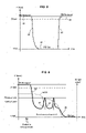
- the park brake lines are purged, i.e. pressure is 0 bar, the park brake is set (ref 92).
- the park brake lines are pressurized, that is to say set to the current pressure prevailing in the reservoir (ref 90, 94).
- the pressure can be 8.5 bar. It is a macroscopic binary behavior.
- the transitions 91, 93 can take some time for the conventional operation of park brake.
- the park brake pressure is controlled to decrease 96 until a significant braking force is applied to the wheels.
- a significant braking force is applied from the moment the park brake pressure reaches the contact point in the park brake line.
- the contact point is set around 4.5 bars.
- the backup deceleration function operates when the park brake pressure is between the contact point and 0 bar.
- the speed of each wheel of the vehicle is monitored by comparing each wheel speed to the vehicle reference speed.
- the vehicle reference speed corresponds to an estimation of the wheel speed of the vehicle. This estimation can for example be equal to the mean value of the speed of the fastest wheels of the vehicle, for instance of the two fastest wheels.
- the park brake lines are pressurized again.
- the park brake pressure has to be set above the release point, typically the release point is set at 5.5 bars.
- the electro-pneumatic braking system could also comprise a duplicated service brake system forming a duplicated deceleration system.
- the duplicated could be used if a failure of the service brake system occurs.
- the park brake used as a backup deceleration system would then be used if both the service brake system and the duplicated service brake failed.
- the electro-pneumatic braking system could also comprise a duplicated park brake system forming a duplicated pneumatic immobilization system.
- the duplicated park brake system would be used if the park brake system failed.
Landscapes
- Engineering & Computer Science (AREA)
- Transportation (AREA)
- Mechanical Engineering (AREA)
- Physics & Mathematics (AREA)
- Fluid Mechanics (AREA)
- Regulating Braking Force (AREA)
- Valves And Accessory Devices For Braking Systems (AREA)
Abstract
Description
- This invention relates to an electro-pneumatic brake system for automotive vehicles, particularly for automated vehicles and/or vehicles having basic or elaborate autonomous drive features, where redundancy is required to cope with a situation where a main deceleration system may become unavailable. In particular, automated vehicles like trucks or medium duty or heavy duty vehicles require an electro-pneumatic brake system which shall exhibit some redundancy.
- This invention also relates to an automotive vehicle equipped with such an electro-pneumatic brake system.
- In the field of automotive vehicles, reliable trajectory control is among the prominent safety features required for ensuring smooth and secure traffic on roads. More particularly, steering and braking function are of utmost importance, let alone drivetrain torque control.
- Automated vehicles require a reliable and powerful braking function. The braking function relies, in particular for trucks, and more generally for heavy duty vehicles, on an electro-pneumatic system using air under pressure as working fluid.
- It has been made compulsory for long to provide two independent pneumatic circuits, as a redundant arrangement in order to keep a braking capability in case one circuit undergoes a failure. The first independent pneumatic circuit provides air supply to a service brake system of the vehicle and the second independent pneumatic circuit provides air supply to a park brake system.
- The service brake system is used to slow down and to stop the vehicle during normal operation, whatever the speed of the vehicle, and thus forms what is called a deceleration system of the vehicle. The park brake system is used mainly to maintain the vehicle stopped when it is not in use, and thus forms what is called an immobilization system of the vehicle.
- Now, with the outlook of autonomous vehicles and vehicle automation, it becomes essential to provide a redundancy of the brake system with trajectory control.
- In documents
WO2019210964 andWO2019210952 , the instant applicant has proposed solutions to implement redundant braking configuration for service braking. However, these solutions are somehow complicated and require various additional components which render the system less cost-effective and heavier. - The inventors have endeavored to find an alternative solution for providing an electro-pneumatic brake system having a redundant deceleration system providing trajectory control which is simple and cost effective.
- According to one aspect of the present invention, it is disclosed an electro-pneumatic brake system for an automotive vehicle comprising:
- a plurality of brake actuators each with a service brake chamber and a park brake chamber,
- a service brake system forming a pneumatic main deceleration system and comprising at least one service brake line configured to supply air pressure to the service brake chamber of at least one of the plurality of brake actuators,
- a park brake system forming on the one hand a pneumatic immobilization system and on the other hand a backup pneumatic deceleration system, and comprising at least one park brake line configured to supply air pressure to the park brake chamber of at least one of the plurality of brake actuators,
- In this arrangement, the backup deceleration system is realized by using the at least one park brake line of the park brake system, providing a simple and cost effective brake system with a redundancy of the deceleration system. In other words, the park brake function is not only use in binary mode for immobilization of the vehicle, but it is also advantageously used in a modulated or regulated fashion under backup deceleration function.
- The redundancy of the deceleration system is achieved without modifying the usual service brake system. Only the park brake system of the vehicle is modified. As the service brake system remains identical to known service park brake system complying with regulations, no further tests are needed for the service brake system to evaluate their compliance with regulations. Only the park brake system needs to be evaluated and/or pass the compliance test(s).
- Moreover, as the park brake system comprises a pressure controller for performing a wheel anti-locking function (ABS function) in the backup deceleration system, it ensures that the trajectory of the vehicle can be controlled when the vehicle is slowed down and stopped during various driving circumstances, even when the backup deceleration system is used instead of the main deceleration system. The pressure controller can for example be a pressure control valve. Modulation/regulation of braking pressure under backup deceleration phase ensures optimal braking even though the normal service braking has underdone a malfunction.
- In various embodiments of the invention, one may possibly have recourse in addition to one and/or other of the following arrangements, taken alone or in combination.
- According to one aspect, the park brake system comprises a stabilization device configured to perform a vehicle stabilization control function under the condition of the park brake system being used as a backup deceleration system, the stabilization device being configured to control the air pressure supply in the at least one park brake line.
- The stabilization device can be on each park brake line or centralized upstream the park brake lines. For example, the stabilization device comprises an electronic brake force distribution system. The stabilization device provides a better control of the trajectory of the vehicle by applying more or less braking pressure ('regulation') to each wheel in order to maximize stopping power whilst maintaining vehicle control, especially in turns and/or curvy roads. Thanks to the stabilization control function, some wheel slippage may be allowed in order to maximize overall braking efficiency, while still maintaining stability (i.e. avoiding swerving).
- According to one aspect, the service brake system comprises main motion sensors including at least main wheel speed sensors, the air pressure supply in the service brake line being controlled depending on main wheel speed signals received from the main wheel speed sensors, and the park brake system comprises backup motion sensors including at least backup wheel speed sensors, the air pressure supply in the park brake line being controlled depending on backup wheel speed signals received from the backup wheel speed sensors under the condition of the park brake system being used as a backup deceleration system.
- The backup deceleration system has its own wheel speed sensors. In case of a failure of the main deceleration system, the backup wheel speed sensors provides a backup wheel speed signal which is independent from the main wheel speed signal. The backup wheel speed sensors thus improves the redundancy of the brake system.
- According to one aspect, the main motion sensors include main stability sensors comprising a main lateral acceleration sensor and/or a main longitudinal acceleration sensor and/or a main yaw rate sensor, the air pressure supply in the service brake line being monitored depending on main stability signals received from the main stability sensors, and the backup motion sensors include backup stability sensors comprising a backup lateral acceleration sensor and/or a backup longitudinal acceleration sensor and/or a backup yaw rate sensor, the air pressure supply in the park brake line being monitored depending on backup stability signals received from the backup stability sensors under the condition of the park brake line being used as a backup deceleration system.
- Lateral sensor, longitudinal sensor, yaw rate sensor are computed to determine in real-time fashion the dynamic behavior of the vehicle. Given this information, the braking system can adapt in real-time the braking force to prevent lateral slippage or veering. The backup deceleration system has its own lateral sensor and/or longitudinal sensor and/or yaw rate sensor. In case of a failure of the main deceleration system, the backup stability sensors provides a backup stability signal which is independent from the main wheel speed signal. The air pressure supply in the park brake lines depends only on the backup stability signal. The backup stability sensors thus improves the redundancy of the brake system. Using
- According to one alternative, the main motion sensors include main stability sensors comprising a main longitudinal acceleration sensor, the air pressure supply in the service brake line being monitored depending on main stability signals received from the main stability sensors, and the backup motion sensors include backup stability sensors comprising a backup longitudinal acceleration sensor, the air pressure supply in the park brake line being monitored depending on backup stability signals received from the backup stability sensors under the condition of the park brake line being used as a backup deceleration system. In this case, longitudinal acceleration sensor is taken as first-order information for behaviour determination.
- According to one alternative, the main motion sensors include main stability sensors comprising a main lateral acceleration sensor and a main longitudinal acceleration sensor, the air pressure supply in the service brake line being monitored depending on main stability signals received from the main stability sensors, and the backup motion sensors include backup stability sensors comprising a backup lateral acceleration sensor and/or a backup longitudinal acceleration sensor, the air pressure supply in the park brake line being monitored depending on backup stability signals received from the backup stability sensors under the condition of the park brake line being used as a backup deceleration system. In this case, longitudinal and lateral acceleration sensors are taken as first-order information for behaviour determination, yaw rate sensor may be optional.
- According to one alternative, the main motion sensors include main stability sensors comprising a main lateral acceleration sensor, a main longitudinal acceleration sensor and a main yaw rate sensor, the air pressure supply in the service brake line being monitored depending on main stability signals received from the main stability sensors, and the backup motion sensors include backup stability sensors comprising a backup lateral acceleration sensor, a backup longitudinal acceleration sensor and a backup yaw rate sensor, the air pressure supply in the park brake line being monitored depending on backup stability signals received from the backup stability sensors under the condition of the park brake line being used as a backup deceleration system. Thanks to data gathered by the three sensors, a complete picture of the dynamic behaviour of the vehicle is determined in real-time.
- According to one aspect, the service brake system comprises at least a service brake control unit configured to receive the main signals from the main motion sensors and to control the air pressure supply in the service brake line depending on the main signals received from the main motion sensors. Also, the service brake control unit receives signals coming from a brake foot pedal provided in the vehicle.
- According to one aspect, the service brake control unit comprises at least one brake module, the service brake control unit being configured to deliver braking control signals to the brake module, and the brake module being configured to control the air pressure supply in the service brake line. Such brake modules are advantageously located not far from the brake actuators at the wheels, thereby minimizing air volume in the piping, minimizing time delay for control.
- According to one aspect, the park brake system comprises a park brake control unit configured to control the air pressure supply in the park brake line. Thus, the conventional function of park brake function can be carried out through park brake control unit. When the park brake control unit purges the park brake lines, then the park brake is set.
- According to one aspect, the, a park brake control unit can be configured to monitor the service brake control unit by continuously checking messages received from the service brake control unit. This carries out watchdog function, so that whenever a malfunction occurs at the service brake control unit, the park brake control unit can take the decision to take over the control of the braking action with at least anti-lock function and preferably stability control function.
- According to one aspect, the park brake system comprises a backup control unit configured to receive the backup signals from the backup motion sensors and to control the air pressure supply in the park brake line depending on the backup signals received form the backup motion sensors under the condition of the park brake system being used as a backup deceleration system.
- According to one alternative, the backup control unit is a single unit comprising the pressure controller device and the stabilization device. Whereby the cost effectiveness of the overall system is improved.
- According to another alternative, the backup control unit comprises the pressure controller device forming a first unit and the stabilization device forming a second unit, the stabilization device being configured to deliver braking control signals to the pressure controller device, and the pressure controller device being configured to control the air pressure supply in the park brake line. Regulation of pressure in the park brake lines can be carried out in values way according to the electrical architecture and computing distribution over one of several control unit(s).
- According to one aspect, the park brake control unit is integral with the backup control unit. Thereby we provide a cost-effective solution.
- According to one aspect, the main motion sensors are connected to the service brake control unit through wired connections and the backup motion sensors are connected to the backup control unit through wired connections.
- According to one aspect, the main motion sensors are connected to a main intermediate module which is configured to receive and send the main signals sent by the main motion sensors to the service brake control unit through a main communication bus, and wherein the backup motion sensors are connected to a backup intermediate module which is configured to receive and send the backup signals sent by the backup motion sensors in the park brake control unit through a backup communication bus which is different from the main communication bus.
- The proposed intermediate modules serve as front-end for data collection from sensors.
- According to one aspect, the main intermediate module and the backup intermediate module are configured to exchange with each other the main signals and the backup signals.
- According to one aspect, the electro-pneumatic brake system comprises a duplicated service brake system forming a duplicated pneumatic deceleration system. This can be useful for compliance about vehicles equipped with full autonomy functions.
- According to one aspect, the electro-pneumatic brake system comprises a duplicated park brake system forming a duplicated pneumatic immobilization system. This can be relevant for compliance about vehicles equipped with full autonomy functions.
- The invention is also directed to an automotive vehicle including an electro-pneumatic brake system as described above.
- Other features and advantages of the invention appear from the following detailed description of two of its embodiments, given by way of non-limiting example, and with reference to the accompanying drawings, in which:
-
Figure 1 illustrates a diagrammatical circuit layout of an electro-pneumatic braking system for a truck according to a first embodiment, -
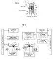
Figure 2 illustrates a brake pneumatic actuator, -
Figure 3 illustrates a functional diagram involving the main deceleration system, the backup desertion system and possibly duplicated deceleration system, -
Figure 4 illustrates a diagrammatical circuit layout of an electro-pneumatic braking system for a truck according to a second embodiment, -
Figure 5 illustrates a time chart relating to a conventional parking brake, -
Figure 6 illustrates a time chart relating to a parking brake system forming a backup deceleration system with regulation. - In the figures, the same references denote identical or similar elements. Unless stated otherwise, the pneumatic lines are shown thicker than the electrical lines.
-
Figure 1 shows a diagrammatical circuit layout of an electro-pneumatic braking system for a truck. The proposed configuration is also valid for any kind of heavy-duty vehicles including buses and coaches. - The truck considered here can be the traction unit in a tractor/trailer configuration or it can be a utility "carrier" truck.
- At least one front axle is a steering axle, without excluding other axle(s) having a steering function including a rear axle.
- The truck considered here can have one or more level(s) of autonomous drive functionalities, entailing reinforced needs for redundancy in braking systems.
- The electro-pneumatic brake system according to the invention comprises four brake actuators RW-L, RW-R, FW-L, FW-R, respectively one for the rear left wheel, one for the rear right wheel, one for the front left wheel and one for the front right wheel. For the sake of clarity we have represented the same brake actuator for all the wheels, but of course, there may be variations and difference according to the location of the wheel (front, rear, trailer etc...).
- There may be also provided more than 4 brake actuators, in case there are two front axles, and/or two or more rear axles. The number of brake actuators can amount to 2,4,6,8, or more. It is worth noting that some brake actuators can be deprived of the parking brake function. The number of brake actuators can be twice the number of axles.
- The brake actuators RW-L, RW-R, FW-L, FW-R can combined service brake and park brake actuators.
- As shown on
figure 2 each brake actuator (generically referred to as BA) includes afirst piston 81 loaded by afirst spring 82 which exerts a first effort E1 in a first direction D1. Brake actuator BA also includes asecond piston 83 loaded by asecond spring 84 which exerts a second effort E2 in a direction D2 opposite to direction D1.Piston 83 is rigid with anoutput rod 88 of brake actuator which drives an associated brake mechanism (brake pads, disc, etc.. not shown). A fixedwall 86 is mounted within ahousing 87 of brake actuator.Wall 86 defines, respectively withpistons rod 88 is coupled to thepiston 83, crosses thewall 86 in an air tight manner and is coupled to thepiston 81.Springs piston 81 in direction D1. This effort is transmitted bypiston 83 torod 88 to actuate the associated brake mechanism in a first direction. Under such circumstances, brake mechanism engages the brake disk(s) or drum(s) of the associated rear left wheel or wheels. This corresponds to a park brake actuation for truck. In other words, when no air under pressure is provided to brake actuator BA, the park brake of truck is actuated. Instead of pistons, flexible membranes or diaphragms can be used. - When air under pressure is provided to the park brake chamber C1 supplied by input PBR (Parking Brake Release, respectively PBR2 or PBR1 for front and rear), the air pressure within this chamber pushes
piston 81 against the action ofspring 82 andspring 84 pushespiston 83 in direction D2. This corresponds to the release of the park brake of truck by air pressure. - When the park brake has been released and if air under pressure is provided to the service brake chamber C2 supplied by input BC (Brake control), the air pressure within the service brake chamber C2 pushes
piston 83 in direction D1 which progressively actuates brake mechanism in order to brake the corresponding wheel or wheels. The mechanical effort delivered by the actuator to the brake mechanism increases with the air pressure delivered to service brake chamber C2. This corresponds to the actuation of the service brake of truck. The service brake actuator is the device which transforms the air pressure into a mechanical force. - Turning now to
figure 1 , the electro-pneumatic brake system comprises a service brake system which supplies air pressure to the service brake chamber C2 of the brake actuators RW-L, RW-R, FW-L, FW-R, respectively through a rear left service brake line LRW-L, a rear right service brake line LRW-R, a front left service brake lines LFW-L, and a front right service brake line LFW-R. - The electro-pneumatic brake system also comprises a park brake system which supplies air pressure to the park brake chamber C1 of the brake actuators RW-L, RW-R, FW-L, FW-R, respectively through a rear park brake line PBR1 and a front park brake line PBR2.
- The service brake system is used to slow down and to stop the vehicle during normal operation, whatever the speed of the vehicle, and thus forms what is called a deceleration system of the vehicle.
- The park brake system is used mainly to maintain the vehicle stopped when it is not in use, and thus forms what is called an immobilization system of the vehicle.
- As it will be described below, the park brake system can also be used to slow down and to stop the vehicle during normal operation, whatever the speed of the vehicle, if a failure of the service brake system occurs. The park brake is thus used as a backup deceleration system.
- As known per se, there is provided a parking brake
electric input device 18 outputting an electric signal S18, for the parking brake operation. The brake system comprises a service brake electric input device 16 (formed generally as a brake foot pedal) delivering a first input electric signal S16 for the service brake operation. - The service brake system comprises main motion sensors comprising main wheel speed sensors WSS and main stability sensors. The main stability sensors comprise a main
lateral acceleration sensor 23b, a mainlongitudinal sensor 23a, and a mainyaw rate sensor 24. Main wheel speed signals and main stability signals sensed by the main motion sensors are received by a service brake control unit. The service brake control unit then controls the air pressure supply in the service brake line depending on the received signals. - In the illustrated example, the service brake control unit comprises a front axle brake module FBM and a rear axle brake module RBM and a service
brake control unit 51. - On
figure 1 , one brake module per axle is represented, e.g. the front axle brake module FBM and the rear axle brake module RBM are represented. However, in other configurations, there may be provided one brake module associated for each brake actuator. A trailer attached to the truck can also comprise similar wheel brake control device. - The front axle brake module FBM provides generally pneumatic control pressure to the left and right front pneumatic brake actuators FW-L, FW-R, through pressure control valves (PCV in short) via the front left service brake line LFW-L and the front right service brake line LFW-R. The front left and right service brake lines LFW-L, LFW-R each connects an output of the front axle brake module FBM with the service brake chamber C2 of respectively the front left and front right braking actuator FW-L, FW-R, and supply air pressure to the corresponding service brake chamber C2.
- Compressed air is supplied, to the front axle brake module FBM and to the rear axle brake module RBM, denoted "Air Supply" at the figures. "Air Supply" provides compressed air at a pressure level slowly evolving over time within a prescribed operating range (in practice it is the pressure prevailing in the reservoir to which the air supply comes from).
- The front axle brake module FBM receives pneumatic braking setpoint through an
electrical control line 12F. The rear axle brake module RBM receives pneumatic braking setpoint through anelectrical control line 12R. - In one embodiment, the front axle brake module FBM receives main wheel speed signals from main wheel speed sensors WSS. Each pressure control valves PCV performs anti-locking function (ABS function) based on the main speed signals. For example, each pressure control valve PCV has a first valve in a series arrangement that can block the passage or air down to the brake chamber, and a second valve that can take out air from the brake chamber circuit and release it to the atmosphere. These valves are controlled in accordance with the real time analysis of the speed of each wheel.
- The rear axle brake module RBM provides generally pneumatic control pressure to the left and right rear pneumatic brake actuators RW-L, RW-R with an arrangement similar to one of the front axle brake module FBM, comprising a rear left service brake line LRW-L and a rear right service brake line LRW-R. And, the rear axle brake module RBM also receives main wheel speed signals from main wheel speed sensors WSS, each pressure control valves PCV performing anti-locking function (ABS function) based on the main speed signals.
- The service
brake control unit 51 delivers braking control signals to the brake modules FBM, RBM. The brake modules FBM, RBM then control the air pressure supply in the service brake lines LFW-L, LFW-R, LRW-L, LRW-R depending on the delivered braking control signal. - Each of the front and rear axle brake modules FBM, RBM, is an electro-pneumatic device, known per se, providing a pneumatic relay function. In short, it selectively takes air from the compressed air supply and selectively releases air to the atmosphere while following faithfully the control signals (electrical and/or pneumatic) send by the service
brake control unit 51. - The service
brake control unit 51 receives main stability signals from the mainlateral acceleration sensor 23b, the mainlongitudinal acceleration sensor 23a throughline 25 and receives signal from and the mainyaw rate sensor 24 throughline 26. The control signals send by the servicebrake control unit 51 to the brake modules FBM, RBM throughlines 12Fbrake control unit 51, and the brake modules FBM, RBM monitor the air pressure supply in the service brake lines depending on the main stability signals. - In an alternate embodiment not shown at the circuit diagram, the wheel speed sensor information is delivered directly to the service brake control unit instead of locally to the front and rear modules. In this case, the braking pressure regulation takes place directly in the
service brake unit 51. - The electro-pneumatic brake system also comprises an air production module 6 ('APM' in short), preferably housing components inside a protective enclosure, thereby providing protection against mechanical and fluid attacks. The air production module 6 is located behind the cabin, accessible from one side of the truck for carrier type truck, or accessible from top side if/when the cabin is tilted or rocked. The air production module 6 may comprise various valves, solenoids, relay valves and pressure sensor.
- There are provided one or more air supply circuit(s) to supply compressed air respectively to the front and rear axle brake modules FBM, RBM, and to supply compressed air generally to the park brake function, and also possibly to a trailer. According to various embodiments, the supply circuit exhibit simple or more advanced redundancy.
- The air production module 6 is in charge of providing said one or more air supply circuit(s), with a pressure level slowly evolving over time within a prescribed operating range. The air production module 6 may comprise two or more air reservoirs, as known per se.
- Two or three air reservoirs (not represented) are connected respectively to first, second and third air supply circuits which are designed to be independent from one another. Air supply circuits have usually a target service pressure set around 12 bars. In practice, air supply circuits may have a service pressure comprised in the range [5 bars - 15 bars], preferably comprised in the range [7 bars - 12 bars].
- The first air supply circuit provides air under pressure to the rear axle brake module RBM, it is sometimes called "primary" circuit. The second air supply circuit provides air under pressure to the front axle brake module FBM. it is sometimes called "secondary" circuit.
- The park brake system comprises a park
brake control unit 61 and a truckPBR relay valve 8. The parkbrake control unit 61 and the truckPBR relay valve 8 are housed in the air production module 6. An air supply circuit supplies in to the truckPBR control valve 8. The parkbrake control unit 61 of the APM 6 controls the air pressure supply in the park brake lines PBR1, PBR2, on the one hand for the conventional park brake function and on the other hand a backup deceleration function. - The parking brake
electric input device 18 outputting an electric signal S18, which is delivered to the parkbrake control unit 61 of the APM 6. Under the normal functioning of the service brake system, the park brake system is used as an immobilization system. The park brake system is actuated by the parking brakeelectric input device 18, in an ON / OFF logic. - The park brake system also comprises backup motion sensors comprising backup wheel speed sensor WSSadd and backup stability sensors comprising a backup
lateral acceleration sensor 33b, a backuplongitudinal sensor 33a, and a backupyaw rate sensor 34. Backup wheel speed signals and backup stability signals sensed respectively by the backup wheels speed sensors WSSadd and the main stability sensors are received by abackup control unit 62. Thebackup control unit 62 can then control the air supply in the park brake lines PBR1, PBR2 depending on the backup signals received, under the condition of the park brake system being used as a backup deceleration system. - The park brake system comprises its own wheel speed sensors and its own stability sensors, thereby providing redundancy with the service brake system. In case of a failure of the service brake system, the control of the braking is done upon the reception of backup wheel speed signals and backup stability signals which are independent from the main wheel speed signal and main stability signals used by the service brake system.
- According to alternate embodiments, the backup deceleration function may use the main motion sensors comprising main wheel speed sensors WSS and main stability sensors, instead of additional sensors.
- According to alternate embodiments, there may be provided twin sensors arranged in a single package. For example at each wheel, a double speed sensor is considered with two independent outputs but housed in a single casing (with one or two connectors).
- The
backup control unit 62 is housed in the air production module 6. Thebackup control unit 62 controls the air pressure supply in the park brake lines PBR1, PBR2 under the condition of the park brake system being used as a backup deceleration system. Thebackup control unit 62 comprises a pressure controller performing a wheel anti-locking function (ABS function) under the condition of the park brake system being used as a backup deceleration system and a stabilization device performing a vehicle stabilization control function under the condition of the park brake system being used as a backup deceleration system. - Thanks to the pressure controller, the trajectory of the vehicle can be mastered when the park brake is used as a backup deceleration system. The pressure controller can for example be a pressure control valve. The stabilization device improves the control of the trajectory of the vehicle by applying more or less braking pressure to each wheel in order to maximize stopping power whilst maintaining vehicle control.
- The park
brake control unit 61 and thebackup control unit 62 are represented as two distinct units. However, according to an alternative, the parkbrake control unit 61 could be integral with thebackup control unit 62. - The air supply provided by the
backup control unit 62 in each park brake lines PBR1, PBR2 is then distributed on each wheel of the vehicle. In the illustrated example, the air supply provided in the rear park brake line PBR1 is distributed on the left and right rear actuators RW-L, RW-R for the left and right rear wheels, and the air supply provided in the front park brake line PBR2 is distributed on the left and right front actuators FW-L, FW-R. - More precisely, as shown at
figure 1 , there is provided a relay function with afront relay valve 42 and arear relay valve 41, both supplied by the centralized air supply, possibly with redundancy. Downstream therear relay valve 41, aleft pipe 43 supplies the park brake chamber of the rear left brake actuator RW-L, aright pipe 44 supplies the park brake chamber of the rear right brake actuator RW-R. Similarly downstream thefront relay valve 42, aleft pipe 45 supplies the park brake chamber of the front left brake actuator FW-L, aright pipe 46 supplies the park brake chamber of the front right brake actuator FW-R. The air volume inpipes backup control unit 62. Response time is much shorter than response time usually encountered in conventional park brake function. - It is to be noted that the term "park brake line(s)" in the claim encompasses generally pneumatic lines between the
backup control unit 62 and the brake actuators, whatever the possible implementations, irrespective of the presence or not of therelay valves 41 42. - There may be a single line, i.e. the single output from the backup control unit. There may be two lines as shown at the figures. It is not excluded to have more than two lines depending on the number of axles to be braked.
- The park
brake control unit 61 provides surveillance of proper operation of the servicebrake control unit 51. To this end, there is provided between those two units a data exchange denoted 14. More precisely, the parkbrake control unit 61 monitors the service brake control unit proper operation by continuously checking messages received from the service brake control unit. This forms a watchdog function, so that whenever a malfunction occurs at the service brake control unit, the park brake control unit makes the decision to take over the control of the braking action. -
Figure 1 represents a vehicle where manned driving is the basic operation, however there is provided driving assistance function(s) like lane/track follow function, preceding vehicle distance regulation, etc, whereasFigure 4 represents a vehicle for which unmanned driving is the basic operation but there is still provided conventional controls. Therefore for the sake of conciseness, all the pneumatic system is similar or identical inFigures 4 and1 , and thus the description is not repeated. Only the high-level controls differ infigure 4 with respect tofigure 1 . - For simple or more advanced autonomous driving, there is provided first and second autonomous
drive control units cameras 75 which provides a flow of images which are analyzed in autonomousdrive control units - Electrical control signals may be conventional electrical control signals on dedicated lines or messages transported on a databus, like a CAN-bus or a like data bus. As exemplified in
figure 1 , aCAN bus 28 establishes a data link between autonomousdrive control units brake control unit 61 and theservice brake unit 51. - Optionally, the first and second autonomous
drive control units electric input device 16. - Turning to
figure 4 , autonomousdrive control units drive control units - Further, there is provided between the two autonomous
drive control units 71,72 a data exchange denoted 74. More precisely the first autonomousdrive control unit 71 monitors the second autonomousdrive control unit 72 proper operation by continuously checking messages received from the second autonomous drive control unit72. Conversely the second autonomous drive control unit72 monitors the first autonomous drive control unit71 proper operation by continuously checking messages received from the first autonomous drive control unit71. - This forms a watchdog function, so that whenever a malfunction occurs at one or the other autonomous drive control units, the other substitutes to take control of the vehicle motion control, including braking.
- On example of connection of the wheel speed sensors and the stability sensors to the service brake system and park brake system is illustrated on
figure 3 . - The main motion sensors are connected to a main
intermediate module 31. The mainintermediate module 31 receives the main wheel speed signals and the main stability signals from the main wheel speed sensors and from the main stability sensors, and sends the main wheel speed signals and the main stability signals to the service brake system, and for example to the service brake control unit, through a main communication bus. - The backup motion sensors are connected to a backup
intermediate module 32. The backupintermediate module 32 receives the backup wheel speed signals and the backup stability signals from the backup wheel speed sensors and from the backup stability sensors, and sends the backup wheel speed signals and the backup stability signals to the park brake system, for example to thebackup control unit 62, through a backup communication bus which is different from the main communication bus. - The main intermediate module and the backup intermediate module can exchange with each other the main signals and the backup signals.
- Therefore, two fully independent braking channels are provided, resulting in high rating redundancy.
- In an unrepresented alternative, the main motion sensors could be connected to the service brake system, and for example to the service brake control unit through wired connections and the backup motion sensors could be connected to the park brake system, for example to the
backup control unit 62 through wired connections. - As illustrated at
figure 5 , under the conventional operation of park brake, only two pressure levels are used. When the park brake lines are purged, i.e. pressure is 0 bar, the park brake is set (ref 92). Conversely, in order to release the park brake, the park brake lines are pressurized, that is to say set to the current pressure prevailing in the reservoir (ref 90, 94). For example, the pressure can be 8.5 bar. It is a macroscopic binary behavior. We note that thetransitions - By contrast, as illustrated in
figure 6 , under the special mode of backup deceleration function, when it is decided that the park brake should take control, at moment T5, the park brake pressure is controlled to decrease 96 until a significant braking force is applied to the wheels. A significant braking force is applied from the moment the park brake pressure reaches the contact point in the park brake line. Typically, the contact point is set around 4.5 bars. When the park brake pressure is above the contact point, the braking force applied to the wheels is not enough to slow down the vehicle. Therefore, the backup deceleration function operates when the park brake pressure is between the contact point and 0 bar. - Thereafter regulation processes is illustrated. In the regulation process, the speed of each wheel of the vehicle is monitored by comparing each wheel speed to the vehicle reference speed. The vehicle reference speed corresponds to an estimation of the wheel speed of the vehicle. This estimation can for example be equal to the mean value of the speed of the fastest wheels of the vehicle, for instance of the two fastest wheels.
- When a wheel speed denoted WSS decreases faster than plausible namely, when the wheel speed reaches a value which is below a predetermined threshold below the vehicle reference speed (which denotes a start of locking), the park brake pressure is controlled to be increased 97 to relief the braking force. The wheel speed thus increases. Responsive to this wheel speed increase up to a value close to the vehicle reference speed, the pressure is decreased again 98 to re-apply a braking force. The above process is iterative and is carried out repeatedly in real time for each wheel.
- This is only a schematic representation of the known anti-locking regulation. On top of that there may be provided a stabilization function where some slippage/locking of one or more wheels is admitted provided that the general stability remains under control (prevention of veering).
- At the end of the regulation phase, there is often a stopping
phase 99 with the speed coming down to a speed sufficiently small that it is not measurable by the system and the spring break fully applies (0 bar). - In order to release the park brake again, the park brake lines are pressurized again. To ensure that the park brake is released, the park brake pressure has to be set above the release point, typically the release point is set at 5.5 bars.
- In order to further increase the redundancy of the electro-pneumatic braking system, the electro-pneumatic braking system could also comprise a duplicated service brake system forming a duplicated deceleration system. The duplicated could be used if a failure of the service brake system occurs. The park brake used as a backup deceleration system would then be used if both the service brake system and the duplicated service brake failed.
- The electro-pneumatic braking system could also comprise a duplicated park brake system forming a duplicated pneumatic immobilization system. The duplicated park brake system would be used if the park brake system failed.
Claims (16)
- An electro-pneumatic brake system for an automotive vehicle comprising:- a plurality of brake actuators (BA, FW-L, FW-R, RW-L, RW-R) each with a service brake chamber (C2) and a park brake chamber (C1),- a service brake system forming a pneumatic main deceleration system and comprising at least one service brake line (LFW-L, LFW-R, LRW-L, LRW-R) configured to supply air pressure to the service brake chamber (C2) of at least one of the plurality of brake actuators,- a park brake system forming on the one hand a pneumatic immobilization system and on the other hand a backup pneumatic deceleration system, and comprising at least one park brake line (PBR1, PBR2) configured to supply air pressure to the park brake chamber (C1) of at least one of the plurality of brake actuators,wherein the park brake system comprises a pressure controller device configured to perform at least a wheel anti-locking function under a condition of the park brake system being used as a backup deceleration system, the pressure controller device being configured to control the air pressure supply in the at least one park brake line.
- The electro-pneumatic brake system according to claim 1, wherein the park brake system comprises a stabilization device configured to perform a vehicle stabilization control function under the condition of the park brake system being used as a backup deceleration system, the stabilization device being configured to control the air pressure supply in the at least one park brake line.
- The pneumatic brake system according to claim 1 or 2, wherein the service brake system comprises main motion sensors including at least main wheel speed sensors (WSS), the air pressure supply in the service brake line being controlled depending on main wheel speed signals received from the main wheel speed sensors, and wherein the park brake system comprises backup motion sensors including at least backup wheel speed sensors (WSS add), the air pressure supply in the park brake line being controlled depending on backup wheel speed signals received from the backup wheel speed sensors under the condition of the park brake system being used as a backup deceleration system.
- The electro-pneumatic brake system according to claim 3, wherein the main motion sensors include main stability sensors comprising a main lateral acceleration sensor (23b) and/or a main longitudinal acceleration sensor (23a) and/or a main yaw rate sensor (24), the air pressure supply in the service brake line being monitored depending on main stability signals received from the main stability sensors, and wherein the backup motion sensors include backup stability sensors comprising a backup lateral acceleration sensor (33b) and/or a backup longitudinal acceleration sensor (33a) and/or a backup yaw rate sensor (34), the air pressure supply in the park brake line being monitored depending on backup stability signals received from the backup stability sensors under the condition of the park brake line being used as a backup deceleration system.
- The electro-pneumatic brake system according to claim 3 or 4, wherein the service brake system comprises at least a service brake control unit configured to receive the main signals from the main motion sensors and to control the air pressure supply in the service brake line depending on the main signals received from the main motion sensors.
- The electro-pneumatic brake system according to claim 5, wherein the service brake system further comprises at least one brake module (FBM, RBM), the service brake control unit being configured to deliver braking control signals to the brake module, and the brake module being configured to control the air pressure supply in the service brake line.
- The electro-pneumatic brake system according to claim 5 or 6, wherein the park brake system comprises a park brake control unit (61) configured to control the air pressure supply in the park brake line.
- The electro-pneumatic brake system according to claim 7, wherein the park brake control unit is configured to monitor the service brake control unit by continuously checking messages received from the service brake control unit.
- The electro-pneumatic brake system according to any one of claims 5 to 8, wherein the park brake system comprises a backup control unit (62) configured to receive the backup signals from the backup motion sensors and to control the air pressure supply in the park brake line depending on the backup signals received form the backup motion sensors under the condition of the park brake system being used as a backup deceleration system.
- The electro-pneumatic brake system according to claim 9, wherein the park brake control unit (61) is integral with the backup control unit (62).
- The electro-pneumatic brake system according to claim 9, wherein the main motion sensors are connected to the service brake control unit through wired connections and the backup motion sensors are connected to the backup control unit through wired connections.
- The electro-pneumatic brake system according to claim 9, wherein the main motion sensors are connected to a main intermediate module which is configured to receive and send the main signals sent by the main motion sensors to the service brake control unit through a main communication bus, and wherein the backup motion sensors are connected to a backup intermediate module which is configured to receive and send the backup signals sent by the backup motion sensors in the park brake control unit through a backup communication bus which is different from the main communication bus.
- The electro-pneumatic brake system according to claim 12, wherein the main intermediate module and the backup intermediate module are configured to exchange with each other the main signals and the backup signals.
- The electro-pneumatic brake system according to any one of claims 1 to 13, comprising a duplicated service brake system forming a duplicated pneumatic deceleration system.
- The electro-pneumatic brake system according to any one of claims 1 to 14, comprising a duplicated park brake system forming a duplicated pneumatic immobilization system.
- An automotive vehicle comprising an electro-pneumatic brake system according to any one of claims 1 to 14.
Priority Applications (3)
| Application Number | Priority Date | Filing Date | Title |
|---|---|---|---|
| EP20207529.7A EP4001031B1 (en) | 2020-11-13 | 2020-11-13 | Electro-pneumatic brake system for a vehicle with a park brake system used as a backup deceleration system |
| US17/521,943 US11904829B2 (en) | 2020-11-13 | 2021-11-09 | Electro-pneumatic brake system for a vehicle with a park brake system used as a backup deceleration system |
| CN202111332063.3A CN114475550A (en) | 2020-11-13 | 2021-11-11 | Electro-pneumatic brake system for a motor vehicle and motor vehicle |
Applications Claiming Priority (1)
| Application Number | Priority Date | Filing Date | Title |
|---|---|---|---|
| EP20207529.7A EP4001031B1 (en) | 2020-11-13 | 2020-11-13 | Electro-pneumatic brake system for a vehicle with a park brake system used as a backup deceleration system |
Publications (3)
| Publication Number | Publication Date |
|---|---|
| EP4001031A1 true EP4001031A1 (en) | 2022-05-25 |
| EP4001031C0 EP4001031C0 (en) | 2024-01-03 |
| EP4001031B1 EP4001031B1 (en) | 2024-01-03 |
Family
ID=73448920
Family Applications (1)
| Application Number | Title | Priority Date | Filing Date |
|---|---|---|---|
| EP20207529.7A Active EP4001031B1 (en) | 2020-11-13 | 2020-11-13 | Electro-pneumatic brake system for a vehicle with a park brake system used as a backup deceleration system |
Country Status (3)
| Country | Link |
|---|---|
| US (1) | US11904829B2 (en) |
| EP (1) | EP4001031B1 (en) |
| CN (1) | CN114475550A (en) |
Citations (2)
| Publication number | Priority date | Publication date | Assignee | Title |
|---|---|---|---|---|
| WO2019210964A1 (en) | 2018-05-03 | 2019-11-07 | Volvo Truck Corporation | Redundant motion control for a vehicle with a redundant braking arrangement |
| WO2019210952A1 (en) | 2018-05-03 | 2019-11-07 | Volvo Truck Corporation | Heavy duty vehicle redundant braking system |
Family Cites Families (6)
| Publication number | Priority date | Publication date | Assignee | Title |
|---|---|---|---|---|
| DE102006041008A1 (en) * | 2006-08-31 | 2008-03-06 | Wabco Gmbh | Pneumatic vehicle brake system and method for controlling such a brake system |
| DE102016005318A1 (en) * | 2016-05-02 | 2017-11-02 | Wabco Gmbh | Electronically controllable pneumatic braking system in a utility vehicle and method for electronically controlling a pneumatic braking system. |
| DE102016012925A1 (en) * | 2016-10-27 | 2018-05-03 | Wabco Gmbh | Method for decelerating a vehicle combination and combination of pneumatic brake systems of the vehicles of a vehicle combination |
| EP3655295B1 (en) * | 2017-07-20 | 2023-06-07 | Volvo Lastvagnar AB | Utilizing a park brake system to improve the deceleration of a vehicle in the event of failure of the service brake system |
| DE102017011611A1 (en) * | 2017-12-15 | 2019-06-19 | Knorr-Bremse Systeme für Nutzfahrzeuge GmbH | Electrical equipment of a vehicle with redundant ABS and driver dynamics control |
| EP4116161B1 (en) * | 2021-07-06 | 2024-03-06 | Volvo Truck Corporation | Heavy duty vehicle redundant braking system |
-
2020
- 2020-11-13 EP EP20207529.7A patent/EP4001031B1/en active Active
-
2021
- 2021-11-09 US US17/521,943 patent/US11904829B2/en active Active
- 2021-11-11 CN CN202111332063.3A patent/CN114475550A/en active Pending
Patent Citations (2)
| Publication number | Priority date | Publication date | Assignee | Title |
|---|---|---|---|---|
| WO2019210964A1 (en) | 2018-05-03 | 2019-11-07 | Volvo Truck Corporation | Redundant motion control for a vehicle with a redundant braking arrangement |
| WO2019210952A1 (en) | 2018-05-03 | 2019-11-07 | Volvo Truck Corporation | Heavy duty vehicle redundant braking system |
Also Published As
| Publication number | Publication date |
|---|---|
| US11904829B2 (en) | 2024-02-20 |
| EP4001031C0 (en) | 2024-01-03 |
| CN114475550A (en) | 2022-05-13 |
| EP4001031B1 (en) | 2024-01-03 |
| US20220153248A1 (en) | 2022-05-19 |
Similar Documents
| Publication | Publication Date | Title |
|---|---|---|
| EP3787944B1 (en) | Redundant motion control for a vehicle with a redundant braking arrangement | |
| EP3626557B1 (en) | Brake system for a vehicle | |
| US20210323522A1 (en) | Brake system for a vehicle, vehicle and method of controlling a brake system for a vehicle | |
| EP3415386B1 (en) | Vehicle brake system | |
| RU2730741C1 (en) | Air preparation unit for vehicle brake of household purpose, braking device and air treatment unit operation method | |
| US11479225B2 (en) | Heavy duty vehicle redundant braking system | |
| JP7104944B2 (en) | air supply system | |
| US11370400B2 (en) | Braking system | |
| CN113518738A (en) | Electro-pneumatic brake system for a commercial vehicle | |
| CN112533805B (en) | Electropneumatic parking brake system with shut-off valve and method for controlling an electronically controlled pneumatic brake system | |
| EP4001031B1 (en) | Electro-pneumatic brake system for a vehicle with a park brake system used as a backup deceleration system | |
| JP6625947B2 (en) | Pneumatic brake system | |
| JP7305856B2 (en) | pneumatic brake system | |
| JP7124152B2 (en) | pneumatic brake system | |
| JP6875493B2 (en) | Pneumatic braking system | |
| US11807202B2 (en) | Brake system for a vehicle |
Legal Events
| Date | Code | Title | Description |
|---|---|---|---|
| PUAI | Public reference made under article 153(3) epc to a published international application that has entered the european phase |
Free format text: ORIGINAL CODE: 0009012 |
|
| STAA | Information on the status of an ep patent application or granted ep patent |
Free format text: STATUS: THE APPLICATION HAS BEEN PUBLISHED |
|
| AK | Designated contracting states |
Kind code of ref document: A1 Designated state(s): AL AT BE BG CH CY CZ DE DK EE ES FI FR GB GR HR HU IE IS IT LI LT LU LV MC MK MT NL NO PL PT RO RS SE SI SK SM TR |
|
| STAA | Information on the status of an ep patent application or granted ep patent |
Free format text: STATUS: REQUEST FOR EXAMINATION WAS MADE |
|
| 17P | Request for examination filed |
Effective date: 20220819 |
|
| RBV | Designated contracting states (corrected) |
Designated state(s): AL AT BE BG CH CY CZ DE DK EE ES FI FR GB GR HR HU IE IS IT LI LT LU LV MC MK MT NL NO PL PT RO RS SE SI SK SM TR |
|
| GRAP | Despatch of communication of intention to grant a patent |
Free format text: ORIGINAL CODE: EPIDOSNIGR1 |
|
| STAA | Information on the status of an ep patent application or granted ep patent |
Free format text: STATUS: GRANT OF PATENT IS INTENDED |
|
| INTG | Intention to grant announced |
Effective date: 20230803 |
|
| GRAS | Grant fee paid |
Free format text: ORIGINAL CODE: EPIDOSNIGR3 |
|
| GRAA | (expected) grant |
Free format text: ORIGINAL CODE: 0009210 |
|
| STAA | Information on the status of an ep patent application or granted ep patent |
Free format text: STATUS: THE PATENT HAS BEEN GRANTED |
|
| RIN1 | Information on inventor provided before grant (corrected) |
Inventor name: MONNIER, MARTIN Inventor name: FARRES, LIONEL |
|
| AK | Designated contracting states |
Kind code of ref document: B1 Designated state(s): AL AT BE BG CH CY CZ DE DK EE ES FI FR GB GR HR HU IE IS IT LI LT LU LV MC MK MT NL NO PL PT RO RS SE SI SK SM TR |
|
| REG | Reference to a national code |
Ref country code: GB Ref legal event code: FG4D |
|
| REG | Reference to a national code |
Ref country code: DE Ref legal event code: R096 Ref document number: 602020023751 Country of ref document: DE |
|
| REG | Reference to a national code |
Ref country code: CH Ref legal event code: EP |
|
| REG | Reference to a national code |
Ref country code: IE Ref legal event code: FG4D |
|
| U01 | Request for unitary effect filed |
Effective date: 20240125 |
|
| U07 | Unitary effect registered |
Designated state(s): AT BE BG DE DK EE FI FR IT LT LU LV MT NL PT SE SI Effective date: 20240202 |
|
| PG25 | Lapsed in a contracting state [announced via postgrant information from national office to epo] |
Ref country code: ES Free format text: LAPSE BECAUSE OF FAILURE TO SUBMIT A TRANSLATION OF THE DESCRIPTION OR TO PAY THE FEE WITHIN THE PRESCRIBED TIME-LIMIT Effective date: 20240103 |
|
| PG25 | Lapsed in a contracting state [announced via postgrant information from national office to epo] |
Ref country code: ES Free format text: LAPSE BECAUSE OF FAILURE TO SUBMIT A TRANSLATION OF THE DESCRIPTION OR TO PAY THE FEE WITHIN THE PRESCRIBED TIME-LIMIT Effective date: 20240103 |