EP4000915A1 - Roof laminate with flexible edges - Google Patents
Roof laminate with flexible edges Download PDFInfo
- Publication number
- EP4000915A1 EP4000915A1 EP20217839.8A EP20217839A EP4000915A1 EP 4000915 A1 EP4000915 A1 EP 4000915A1 EP 20217839 A EP20217839 A EP 20217839A EP 4000915 A1 EP4000915 A1 EP 4000915A1
- Authority
- EP
- European Patent Office
- Prior art keywords
- laminate
- strip
- active
- layer
- film
- Prior art date
- Legal status (The legal status is an assumption and is not a legal conclusion. Google has not performed a legal analysis and makes no representation as to the accuracy of the status listed.)
- Granted
Links
Images


Classifications
-
- B—PERFORMING OPERATIONS; TRANSPORTING
- B32—LAYERED PRODUCTS
- B32B—LAYERED PRODUCTS, i.e. PRODUCTS BUILT-UP OF STRATA OF FLAT OR NON-FLAT, e.g. CELLULAR OR HONEYCOMB, FORM
- B32B5/00—Layered products characterised by the non- homogeneity or physical structure, i.e. comprising a fibrous, filamentary, particulate or foam layer; Layered products characterised by having a layer differing constitutionally or physically in different parts
- B32B5/02—Layered products characterised by the non- homogeneity or physical structure, i.e. comprising a fibrous, filamentary, particulate or foam layer; Layered products characterised by having a layer differing constitutionally or physically in different parts characterised by structural features of a fibrous or filamentary layer
-
- B—PERFORMING OPERATIONS; TRANSPORTING
- B32—LAYERED PRODUCTS
- B32B—LAYERED PRODUCTS, i.e. PRODUCTS BUILT-UP OF STRATA OF FLAT OR NON-FLAT, e.g. CELLULAR OR HONEYCOMB, FORM
- B32B3/00—Layered products comprising a layer with external or internal discontinuities or unevennesses, or a layer of non-planar shape; Layered products comprising a layer having particular features of form
- B32B3/26—Layered products comprising a layer with external or internal discontinuities or unevennesses, or a layer of non-planar shape; Layered products comprising a layer having particular features of form characterised by a particular shape of the outline of the cross-section of a continuous layer; characterised by a layer with cavities or internal voids ; characterised by an apertured layer
- B32B3/266—Layered products comprising a layer with external or internal discontinuities or unevennesses, or a layer of non-planar shape; Layered products comprising a layer having particular features of form characterised by a particular shape of the outline of the cross-section of a continuous layer; characterised by a layer with cavities or internal voids ; characterised by an apertured layer characterised by an apertured layer, the apertures going through the whole thickness of the layer, e.g. expanded metal, perforated layer, slit layer regular cells B32B3/12
-
- B—PERFORMING OPERATIONS; TRANSPORTING
- B32—LAYERED PRODUCTS
- B32B—LAYERED PRODUCTS, i.e. PRODUCTS BUILT-UP OF STRATA OF FLAT OR NON-FLAT, e.g. CELLULAR OR HONEYCOMB, FORM
- B32B15/00—Layered products comprising a layer of metal
- B32B15/04—Layered products comprising a layer of metal comprising metal as the main or only constituent of a layer, which is next to another layer of the same or of a different material
- B32B15/08—Layered products comprising a layer of metal comprising metal as the main or only constituent of a layer, which is next to another layer of the same or of a different material of synthetic resin
-
- B—PERFORMING OPERATIONS; TRANSPORTING
- B32—LAYERED PRODUCTS
- B32B—LAYERED PRODUCTS, i.e. PRODUCTS BUILT-UP OF STRATA OF FLAT OR NON-FLAT, e.g. CELLULAR OR HONEYCOMB, FORM
- B32B15/00—Layered products comprising a layer of metal
- B32B15/14—Layered products comprising a layer of metal next to a fibrous or filamentary layer
-
- B—PERFORMING OPERATIONS; TRANSPORTING
- B32—LAYERED PRODUCTS
- B32B—LAYERED PRODUCTS, i.e. PRODUCTS BUILT-UP OF STRATA OF FLAT OR NON-FLAT, e.g. CELLULAR OR HONEYCOMB, FORM
- B32B15/00—Layered products comprising a layer of metal
- B32B15/20—Layered products comprising a layer of metal comprising aluminium or copper
-
- B—PERFORMING OPERATIONS; TRANSPORTING
- B32—LAYERED PRODUCTS
- B32B—LAYERED PRODUCTS, i.e. PRODUCTS BUILT-UP OF STRATA OF FLAT OR NON-FLAT, e.g. CELLULAR OR HONEYCOMB, FORM
- B32B27/00—Layered products comprising a layer of synthetic resin
- B32B27/12—Layered products comprising a layer of synthetic resin next to a fibrous or filamentary layer
-
- B—PERFORMING OPERATIONS; TRANSPORTING
- B32—LAYERED PRODUCTS
- B32B—LAYERED PRODUCTS, i.e. PRODUCTS BUILT-UP OF STRATA OF FLAT OR NON-FLAT, e.g. CELLULAR OR HONEYCOMB, FORM
- B32B27/00—Layered products comprising a layer of synthetic resin
- B32B27/32—Layered products comprising a layer of synthetic resin comprising polyolefins
-
- B—PERFORMING OPERATIONS; TRANSPORTING
- B32—LAYERED PRODUCTS
- B32B—LAYERED PRODUCTS, i.e. PRODUCTS BUILT-UP OF STRATA OF FLAT OR NON-FLAT, e.g. CELLULAR OR HONEYCOMB, FORM
- B32B27/00—Layered products comprising a layer of synthetic resin
- B32B27/34—Layered products comprising a layer of synthetic resin comprising polyamides
-
- B—PERFORMING OPERATIONS; TRANSPORTING
- B32—LAYERED PRODUCTS
- B32B—LAYERED PRODUCTS, i.e. PRODUCTS BUILT-UP OF STRATA OF FLAT OR NON-FLAT, e.g. CELLULAR OR HONEYCOMB, FORM
- B32B3/00—Layered products comprising a layer with external or internal discontinuities or unevennesses, or a layer of non-planar shape; Layered products comprising a layer having particular features of form
- B32B3/02—Layered products comprising a layer with external or internal discontinuities or unevennesses, or a layer of non-planar shape; Layered products comprising a layer having particular features of form characterised by features of form at particular places, e.g. in edge regions
- B32B3/08—Layered products comprising a layer with external or internal discontinuities or unevennesses, or a layer of non-planar shape; Layered products comprising a layer having particular features of form characterised by features of form at particular places, e.g. in edge regions characterised by added members at particular parts
-
- B—PERFORMING OPERATIONS; TRANSPORTING
- B32—LAYERED PRODUCTS
- B32B—LAYERED PRODUCTS, i.e. PRODUCTS BUILT-UP OF STRATA OF FLAT OR NON-FLAT, e.g. CELLULAR OR HONEYCOMB, FORM
- B32B5/00—Layered products characterised by the non- homogeneity or physical structure, i.e. comprising a fibrous, filamentary, particulate or foam layer; Layered products characterised by having a layer differing constitutionally or physically in different parts
- B32B5/02—Layered products characterised by the non- homogeneity or physical structure, i.e. comprising a fibrous, filamentary, particulate or foam layer; Layered products characterised by having a layer differing constitutionally or physically in different parts characterised by structural features of a fibrous or filamentary layer
- B32B5/022—Non-woven fabric
-
- B—PERFORMING OPERATIONS; TRANSPORTING
- B32—LAYERED PRODUCTS
- B32B—LAYERED PRODUCTS, i.e. PRODUCTS BUILT-UP OF STRATA OF FLAT OR NON-FLAT, e.g. CELLULAR OR HONEYCOMB, FORM
- B32B5/00—Layered products characterised by the non- homogeneity or physical structure, i.e. comprising a fibrous, filamentary, particulate or foam layer; Layered products characterised by having a layer differing constitutionally or physically in different parts
- B32B5/02—Layered products characterised by the non- homogeneity or physical structure, i.e. comprising a fibrous, filamentary, particulate or foam layer; Layered products characterised by having a layer differing constitutionally or physically in different parts characterised by structural features of a fibrous or filamentary layer
- B32B5/024—Woven fabric
-
- B—PERFORMING OPERATIONS; TRANSPORTING
- B32—LAYERED PRODUCTS
- B32B—LAYERED PRODUCTS, i.e. PRODUCTS BUILT-UP OF STRATA OF FLAT OR NON-FLAT, e.g. CELLULAR OR HONEYCOMB, FORM
- B32B5/00—Layered products characterised by the non- homogeneity or physical structure, i.e. comprising a fibrous, filamentary, particulate or foam layer; Layered products characterised by having a layer differing constitutionally or physically in different parts
- B32B5/02—Layered products characterised by the non- homogeneity or physical structure, i.e. comprising a fibrous, filamentary, particulate or foam layer; Layered products characterised by having a layer differing constitutionally or physically in different parts characterised by structural features of a fibrous or filamentary layer
- B32B5/028—Net structure, e.g. spaced apart filaments bonded at the crossing points
-
- B—PERFORMING OPERATIONS; TRANSPORTING
- B32—LAYERED PRODUCTS
- B32B—LAYERED PRODUCTS, i.e. PRODUCTS BUILT-UP OF STRATA OF FLAT OR NON-FLAT, e.g. CELLULAR OR HONEYCOMB, FORM
- B32B7/00—Layered products characterised by the relation between layers; Layered products characterised by the relative orientation of features between layers, or by the relative values of a measurable parameter between layers, i.e. products comprising layers having different physical, chemical or physicochemical properties; Layered products characterised by the interconnection of layers
- B32B7/02—Physical, chemical or physicochemical properties
- B32B7/022—Mechanical properties
-
- B—PERFORMING OPERATIONS; TRANSPORTING
- B32—LAYERED PRODUCTS
- B32B—LAYERED PRODUCTS, i.e. PRODUCTS BUILT-UP OF STRATA OF FLAT OR NON-FLAT, e.g. CELLULAR OR HONEYCOMB, FORM
- B32B7/00—Layered products characterised by the relation between layers; Layered products characterised by the relative orientation of features between layers, or by the relative values of a measurable parameter between layers, i.e. products comprising layers having different physical, chemical or physicochemical properties; Layered products characterised by the interconnection of layers
- B32B7/04—Interconnection of layers
- B32B7/12—Interconnection of layers using interposed adhesives or interposed materials with bonding properties
-
- B—PERFORMING OPERATIONS; TRANSPORTING
- B32—LAYERED PRODUCTS
- B32B—LAYERED PRODUCTS, i.e. PRODUCTS BUILT-UP OF STRATA OF FLAT OR NON-FLAT, e.g. CELLULAR OR HONEYCOMB, FORM
- B32B7/00—Layered products characterised by the relation between layers; Layered products characterised by the relative orientation of features between layers, or by the relative values of a measurable parameter between layers, i.e. products comprising layers having different physical, chemical or physicochemical properties; Layered products characterised by the interconnection of layers
- B32B7/04—Interconnection of layers
- B32B7/12—Interconnection of layers using interposed adhesives or interposed materials with bonding properties
- B32B7/14—Interconnection of layers using interposed adhesives or interposed materials with bonding properties applied in spaced arrangements, e.g. in stripes
-
- E—FIXED CONSTRUCTIONS
- E04—BUILDING
- E04D—ROOF COVERINGS; SKY-LIGHTS; GUTTERS; ROOF-WORKING TOOLS
- E04D12/00—Non-structural supports for roofing materials, e.g. battens, boards
-
- E—FIXED CONSTRUCTIONS
- E04—BUILDING
- E04D—ROOF COVERINGS; SKY-LIGHTS; GUTTERS; ROOF-WORKING TOOLS
- E04D12/00—Non-structural supports for roofing materials, e.g. battens, boards
- E04D12/002—Sheets of flexible material, e.g. roofing tile underlay
-
- B—PERFORMING OPERATIONS; TRANSPORTING
- B32—LAYERED PRODUCTS
- B32B—LAYERED PRODUCTS, i.e. PRODUCTS BUILT-UP OF STRATA OF FLAT OR NON-FLAT, e.g. CELLULAR OR HONEYCOMB, FORM
- B32B2250/00—Layers arrangement
- B32B2250/02—2 layers
-
- B—PERFORMING OPERATIONS; TRANSPORTING
- B32—LAYERED PRODUCTS
- B32B—LAYERED PRODUCTS, i.e. PRODUCTS BUILT-UP OF STRATA OF FLAT OR NON-FLAT, e.g. CELLULAR OR HONEYCOMB, FORM
- B32B2250/00—Layers arrangement
- B32B2250/03—3 layers
-
- B—PERFORMING OPERATIONS; TRANSPORTING
- B32—LAYERED PRODUCTS
- B32B—LAYERED PRODUCTS, i.e. PRODUCTS BUILT-UP OF STRATA OF FLAT OR NON-FLAT, e.g. CELLULAR OR HONEYCOMB, FORM
- B32B2250/00—Layers arrangement
- B32B2250/04—4 layers
-
- B—PERFORMING OPERATIONS; TRANSPORTING
- B32—LAYERED PRODUCTS
- B32B—LAYERED PRODUCTS, i.e. PRODUCTS BUILT-UP OF STRATA OF FLAT OR NON-FLAT, e.g. CELLULAR OR HONEYCOMB, FORM
- B32B2250/00—Layers arrangement
- B32B2250/44—Number of layers variable across the laminate
-
- B—PERFORMING OPERATIONS; TRANSPORTING
- B32—LAYERED PRODUCTS
- B32B—LAYERED PRODUCTS, i.e. PRODUCTS BUILT-UP OF STRATA OF FLAT OR NON-FLAT, e.g. CELLULAR OR HONEYCOMB, FORM
- B32B2274/00—Thermoplastic elastomer material
-
- B—PERFORMING OPERATIONS; TRANSPORTING
- B32—LAYERED PRODUCTS
- B32B—LAYERED PRODUCTS, i.e. PRODUCTS BUILT-UP OF STRATA OF FLAT OR NON-FLAT, e.g. CELLULAR OR HONEYCOMB, FORM
- B32B2307/00—Properties of the layers or laminate
- B32B2307/30—Properties of the layers or laminate having particular thermal properties
- B32B2307/304—Insulating
-
- B—PERFORMING OPERATIONS; TRANSPORTING
- B32—LAYERED PRODUCTS
- B32B—LAYERED PRODUCTS, i.e. PRODUCTS BUILT-UP OF STRATA OF FLAT OR NON-FLAT, e.g. CELLULAR OR HONEYCOMB, FORM
- B32B2307/00—Properties of the layers or laminate
- B32B2307/50—Properties of the layers or laminate having particular mechanical properties
- B32B2307/54—Yield strength; Tensile strength
-
- B—PERFORMING OPERATIONS; TRANSPORTING
- B32—LAYERED PRODUCTS
- B32B—LAYERED PRODUCTS, i.e. PRODUCTS BUILT-UP OF STRATA OF FLAT OR NON-FLAT, e.g. CELLULAR OR HONEYCOMB, FORM
- B32B2307/00—Properties of the layers or laminate
- B32B2307/50—Properties of the layers or laminate having particular mechanical properties
- B32B2307/542—Shear strength
-
- B—PERFORMING OPERATIONS; TRANSPORTING
- B32—LAYERED PRODUCTS
- B32B—LAYERED PRODUCTS, i.e. PRODUCTS BUILT-UP OF STRATA OF FLAT OR NON-FLAT, e.g. CELLULAR OR HONEYCOMB, FORM
- B32B2307/00—Properties of the layers or laminate
- B32B2307/70—Other properties
- B32B2307/724—Permeability to gases, adsorption
-
- B—PERFORMING OPERATIONS; TRANSPORTING
- B32—LAYERED PRODUCTS
- B32B—LAYERED PRODUCTS, i.e. PRODUCTS BUILT-UP OF STRATA OF FLAT OR NON-FLAT, e.g. CELLULAR OR HONEYCOMB, FORM
- B32B2307/00—Properties of the layers or laminate
- B32B2307/70—Other properties
- B32B2307/726—Permeability to liquids, absorption
- B32B2307/7265—Non-permeable
-
- B—PERFORMING OPERATIONS; TRANSPORTING
- B32—LAYERED PRODUCTS
- B32B—LAYERED PRODUCTS, i.e. PRODUCTS BUILT-UP OF STRATA OF FLAT OR NON-FLAT, e.g. CELLULAR OR HONEYCOMB, FORM
- B32B2419/00—Buildings or parts thereof
- B32B2419/06—Roofs, roof membranes
Definitions
- the invention relates to laminates that are used in the construction of roofs and a method to join two laminates.
- Laminates or underlays for roofs include a reinforcement element and an active element, which provides appropriate insulation and water-tightness of the laminate.
- the laminate may be placed towards the outside of the house, i.e. above the rafters and below the tiles or towards the inside, i.e. below the rafters.
- the active element When used in the outside, above the rafters of the roof, the active element usually has a microporous film, for example PP or PE or a monolithic element, for example TPU or TPE film, that allows vapour transfer from the inside to the outside of the roof.
- a protective layer for example a spunbond may be placed above the active film so as to protect it.
- the active film When the laminate is placed below the rafters, the active film may be a vapour control element with a film that has a variable vapour transmission capacity so as to control the vapour transmission from the inside to the outside of the construction.
- Materials used for the vapour control film are for example polypropylene (PP), polyethylene (PE), and polyamide (PA),
- two adjacent laminates are joined together by attaching a strip of one laminate to a strip of the other laminate.
- Known laminates are attached to each other by thermal adhesion, such as thermal adhesion of TPU layers.
- An object of the invention is a laminate that permits a strong bonding between adjacent laminates.
- a further object of the invention is a roof construction that is water-tight.
- a further object of the invention is an environmental friendly roof construction.
- a further object of the invention is an energy-saving roof construction.
- a further object of the invention is a method to join two adjacent laminates on a roof, as well as laminates that facilitate their effective bonding to each other.
- a laminate for roofs according to the invention includes a reinforcement element and an active element.
- the active element which provides the water-tightness of the laminate, is more flexible rather than the reinforcement element and has a strip overhanging beyond an edge of the reinforcement element.
- a method to attach two adjacent laminates includes the following steps: a) bring in an overlapping disposition the two laminates so that a strip of one laminate contacts a strip of the other laminate, whereby the strip of one laminate is more flexible that the strip of the other laminate, b) tighten the strip that has lower flexibility on the other strip, c) attach the two strips with an adhesive material.
- the preparation for the joining of two adjacent laminates is facilitated, when the strength of one laminate is more flexible than the adjacent laminate, because the more flexible laminate can be stretched over less the flexible laminate, so as to avoid air-gaps in between.
- a laminate according to the invention this is achieved by providing a strip of the active element with higher flexibility beyond the edge of the reinforcement element.
- Flexibility is controlled through the strength of the laminate, in particular the tensile strength.
- An adhesive material for example an adhesive tape, is provided along the overhanging strip and to a face of the active element, which is in contact with the reinforcement element.
- the adhesive material is used to attach the laminate to an adjacent laminate, when laying the laminate of a roof, with cold bonding.
- the flexibility of the elements may be controlled by their tensile strength. To this end the tensile strength of the active element of a laminate is lower than the tensile strength of its reinforcement element so that the overhanging strip is more flexible than reinforcement element and the laminate. When two laminates are joined together, the more flexible strip of one laminate is joint along a more rigid edge of its adjacent laminate, i.e. along a strip of the adjacent laminate which includes a strip-portion of the reinforcement element of the adjacent laminate.
- the reinforcement element may be a net or a woven fabric. In some examples the reinforcement element may be multi-layer.
- the active element may be a monolithic or a microporous breathable layer.
- the material of the monolithic layer may be or may contain TPU or TPE.
- the active element may include a vapour control layer with variable varpour permeability that controls the vapour transmission through it.
- the vapour control layer is made of polypropylene (PP), polyethylene (PE), polyamide (PA), TPU or TPE or includes polypropylene (PP), polyethylene (PE), polyamide (PA), thermoplastic polyurethane (TPU) or thermoplastic elastomer (TPE).
- the active element contains a protective layer, for example spunbond layer, to protect the active film.
- a protective layer for example spunbond layer
- the laminate has four layers, i.e. a spunbond and an active layer that form the active element and a woven fabric or net and spunbond that form the reinforcement layer.
- the laminate may be a sandwich between two spunbonds.
- the active element includes a spunbond layer and an active film and the reinforcement element includes a woven fabric.
- the film is usually in-between the spunbond and the woven fabric.
- Further advantages are offered, when joining of adjacent laminates is effected between the active layers, such as between the active films.
- a laminate may have a further strip other than the strip overhanging the reinforcement element, which extends beyond an edge of the spunbond layer and includes a strip-portion of the active film and a strip-portion the woven fabric.
- a strip of adhesive material preferably an adhesive tape, is provided along the further strip on the active film.
- the strip overhanging the reinforcement element and the further strip are provided along opposite edges of the laminate or along adjacent edges of the laminate.
- the active element or the reinforcement element may further include an aluminum porous or continuous foil.
- a porous or continuous metallized film may be used instead of an aluminum foil.
- a laminate according to the invention has a high tensile strength and provides high shear strength of the joint when two adjacent laminates are attached to each other.
- the joint of the adjacent laminates is air-tight and water tight, since there are no air gaps that damage the air- and water- tightness of the joint. Further the strength under transverse loading is high because of the reinforcement.
- tensile strength of 500 N per 5 cm of edge width of the laminate may be exceeded.
- FIG. 1 shows an example of a laminate (1) according to the invention.
- the laminate (1) has three layers, a top layer that is a spunbond (21), a middle layer that is an active film (25) and a bottom layer that is a woven fabric (11).
- the film may consist of or include different materials, such as PP, PE, PA, TPU, TPE.
- the film In laminates that are to be used as outer breathable roofing membranes, i.e. above the rafters and/or the thermal insulation, the film may be microporous or monolithic. In laminates that are to be used as inner laminates, i.e. below the rafters and/or the thermal insulation, the film may be a vapour control layer.
- the strength of the woven fabric (11) provides an additional stiffness to the laminate (1) and enables an improved lay-down of the laminate (1) on horizontal or inclined, pitched, roofs so that the laminate (1) can be strongly pulled over the rafters, when the laminate (1) is used above the rafters.
- the width of the spunbond (21) and the active film (25) is larger than the width of the woven fabric (11), so that the laminate (1) has a very flexible and soft strip (60) that overhangs beyond the more rigid and stronger woven fabric (11).
- the width of the active element (20), i.e. the spunbond (21) and the film (25) is 2 cm to 15 cm larger, preferably 10 to 15 cm larger, than the width of the reinforcement element (10).
- the active element (20) of the overhanging strip (60) is covered at least partially over its width with an adhesive material, for example an adhesive tape (31) of pressure sensitive adhesive (PSA).
- PSA pressure sensitive adhesive
- the adjacent laminate has a further adhesive material (31) along a strip on the spunbond (21) that in use will be joint to the corresponding adhesive material (31) of the overhanging strip (60), as schematically is shown in Figure 3 , by cold bonding, i.e. without requiring input of thermal energy.
- the adhesive material (31) may be protected by a liner not shown in the Figures before connecting the laminates (1) together.
- the adhesive material is applied on the film of the soft edge and on the top side of the spunbond of the adjacent laminate, so as to form a joint between a soft strip of one laminate and a strong strip of the other laminate. Bu attaching a soft strip to a relative harder strip, it is easy to avoid the wavy performance and the subsequent air-gaps between overlapping strips of adjacent laminates, such as those shown in Figure 2 .
- the film (25) and the woven fabric (11) attached to it form an overhanging strip that extends beyond an edge of the spunbond (21).
- This strip of active film (25) and woven fabric (11) is much stronger than the overhanging strip (60), because it includes the woven fabric (11).
- Soft and flexible strip (60) is designated as a "soft edge” or "open edge”.
- the adhesive material (31) is applied on the active film (25) rather than on the spunbond (21), a feature that provides a stronger and more durable joint between adjacent laminates, as the cohesion is effected between two active films (25).
- the joint of a soft, more flexible, strip and a strong, less flexible, strip enables a complete adhesion of two laminates over the full area of the roof, so that gaps along the joints are avoided and the joints establish a watertight and airtight connection between the laminates.
- Such a connection may be achieved between two adjacent laminates either by providing the adhesion material on the active film of one laminate and on the spunbond on the other, as shown schematically in Figure 3 , or by providing the adhesive material on the active film of both laminates, as schematically shown in Figure 4 .
- the laminate has a high tensile strength and provides high shear strength of the joint when two adjacent laminates are attached to each other.
- the joint of the adjacent laminates is air-tight and water tight, since there are no air gaps that damage the air- and water- tightness of the joint. Further, the strength under transverse loading is high and with a laminate of the invention the tensile strength exceeds 500 N per 5 cm of edge width of the laminate. Thus, damages and accidents are avoided, when during construction, the user steps on a laminate between the rafters of a roof.
- One example consists of three layers, a spunbond and an active film that make the active element and a woven fabric or a net, with the film being in between the spunbond and the woven fabric or net.
- the face of the woven fabric is also covered by a spunbond.
- the reinforcement element (10) When used towards the outside of the roof the reinforcement element (10) has a woven fabric (11) and the active element (20) has a monolithic film (25), for example of TPU or TPE or containing TPU or TPE.
- the laminate (1) is placed with the reinforcement element (10) below the active element (20), i.e. towards the interior of the building.
- the reinforcement element (10) has a woven fabric (11) and a further aluminum perforated or closed foil (40), which acts as a heat reflector, and the active element (20) has a microporous film (25) and a spunbond (21), for example of PP or PE or containing PP or PE.
- the laminate (1) is placed with the reinforcement element (10) above the active element (20), i.e. facing the exterior of the building.
- the reinforcement element (10) When used towards the inside the reinforcement element (10) has a woven fabric (11) and the active element (20) has a monolithic vapour control layer (25) and a spunbond (21) for protection.
- this laminate (1) is placed with the reinforcement element (10) above the active element, i.e. facing outside of the building.
- the reinforcement element (10) has a woven fabric (11) and a further aluminum perforated or closed foil (40), which acts a heat reflector and the active element (20) has a monolithic vapour control layer (25) and a spunbond (221 for protection.
- this laminate (1) is placed with the reinforcement element (10) below the active element (20), i.e. facing inside.
- the aluminum foil (40) may be part of the active element (20) rather than of the reinforcement element (10), for example by attaching it to the spunbond (21).
- the spunbond (21) Such an example is schematically presented in Figure 6 that shows a laminate with an aluminum foil (40), a spunbond (21), an active film (20) and a woven fabric (11).
- a porous or continuous metallized film, preferably with aluminum, may be used instead of an aluminum foil.
- the width of the laminate may be 100 cm to 300 cm and its weight 140 gr/m 2 to 350 gr/m 2 - not including the weight of the adhesive tape.
- the open edge, i.e. the overhanding strip (60) of the active element has a width of 2 cm to 20 cm, preferably between 10 cm and 20 cm and the adhesive tape has a width of equal of less than the width of the overhanging strip (60).
- the weight of the adhesion tape may be between 60 gr/m 2 to 200 gr/m 2 .
Landscapes
- Engineering & Computer Science (AREA)
- Architecture (AREA)
- Civil Engineering (AREA)
- Structural Engineering (AREA)
- Textile Engineering (AREA)
- Mechanical Engineering (AREA)
- Laminated Bodies (AREA)
Abstract
Description
- The invention relates to laminates that are used in the construction of roofs and a method to join two laminates.
- Laminates or underlays for roofs include a reinforcement element and an active element, which provides appropriate insulation and water-tightness of the laminate. The laminate may be placed towards the outside of the house, i.e. above the rafters and below the tiles or towards the inside, i.e. below the rafters.
- When used in the outside, above the rafters of the roof, the active element usually has a microporous film, for example PP or PE or a monolithic element, for example TPU or TPE film, that allows vapour transfer from the inside to the outside of the roof. A protective layer, for example a spunbond may be placed above the active film so as to protect it.
- When the laminate is placed below the rafters, the active film may be a vapour control element with a film that has a variable vapour transmission capacity so as to control the vapour transmission from the inside to the outside of the construction. Materials used for the vapour control film are for example polypropylene (PP), polyethylene (PE), and polyamide (PA),
- It is also possible to build a roof with a laminate above the rafters and a further laminate below the rafters. In such cases it is usual to have an insulation layer between the outer laminate and the inner laminate.
- When building a roof, two adjacent laminates are joined together by attaching a strip of one laminate to a strip of the other laminate. Known laminates are attached to each other by thermal adhesion, such as thermal adhesion of TPU layers.
- An object of the invention is a laminate that permits a strong bonding between adjacent laminates. A further object of the invention is a roof construction that is water-tight. A further object of the invention is an environmental friendly roof construction. A further object of the invention is an energy-saving roof construction. A further object of the invention is a method to join two adjacent laminates on a roof, as well as laminates that facilitate their effective bonding to each other.
- The invention is defined in the independent claims.
- A laminate for roofs according to the invention includes a reinforcement element and an active element. The active element, which provides the water-tightness of the laminate, is more flexible rather than the reinforcement element and has a strip overhanging beyond an edge of the reinforcement element.
- A method to attach two adjacent laminates according to the invention includes the following steps: a) bring in an overlapping disposition the two laminates so that a strip of one laminate contacts a strip of the other laminate, whereby the strip of one laminate is more flexible that the strip of the other laminate, b) tighten the strip that has lower flexibility on the other strip, c) attach the two strips with an adhesive material.
- The preparation for the joining of two adjacent laminates is facilitated, when the strength of one laminate is more flexible than the adjacent laminate, because the more flexible laminate can be stretched over less the flexible laminate, so as to avoid air-gaps in between. With a laminate according to the invention, this is achieved by providing a strip of the active element with higher flexibility beyond the edge of the reinforcement element. Thus, water-tightness, effective insulation and effective bonding is achieved without compromising the strength of any laminate. Flexibility is controlled through the strength of the laminate, in particular the tensile strength.
- The dependent claims define further features that offer further advantages when combined with the features of the invention.
- An adhesive material, for example an adhesive tape, is provided along the overhanging strip and to a face of the active element, which is in contact with the reinforcement element. The adhesive material is used to attach the laminate to an adjacent laminate, when laying the laminate of a roof, with cold bonding.
- The flexibility of the elements may be controlled by their tensile strength. To this end the tensile strength of the active element of a laminate is lower than the tensile strength of its reinforcement element so that the overhanging strip is more flexible than reinforcement element and the laminate. When two laminates are joined together, the more flexible strip of one laminate is joint along a more rigid edge of its adjacent laminate, i.e. along a strip of the adjacent laminate which includes a strip-portion of the reinforcement element of the adjacent laminate.
- The reinforcement element may be a net or a woven fabric. In some examples the reinforcement element may be multi-layer.
- The active element may be a monolithic or a microporous breathable layer. The material of the monolithic layer may be or may contain TPU or TPE.
- Alternatively the active element may include a vapour control layer with variable varpour permeability that controls the vapour transmission through it. The vapour control layer is made of polypropylene (PP), polyethylene (PE), polyamide (PA), TPU or TPE or includes polypropylene (PP), polyethylene (PE), polyamide (PA), thermoplastic polyurethane (TPU) or thermoplastic elastomer (TPE).
- Preferably the active element contains a protective layer, for example spunbond layer, to protect the active film.
- Is some examples of the invention the laminate has four layers, i.e. a spunbond and an active layer that form the active element and a woven fabric or net and spunbond that form the reinforcement layer. In general the laminate may be a sandwich between two spunbonds.
- In some examples, the active element includes a spunbond layer and an active film and the reinforcement element includes a woven fabric. The film is usually in-between the spunbond and the woven fabric. Further advantages are offered, when joining of adjacent laminates is effected between the active layers, such as between the active films. To this end a laminate may have a further strip other than the strip overhanging the reinforcement element, which extends beyond an edge of the spunbond layer and includes a strip-portion of the active film and a strip-portion the woven fabric. A strip of adhesive material, preferably an adhesive tape, is provided along the further strip on the active film. The strip overhanging the reinforcement element and the further strip are provided along opposite edges of the laminate or along adjacent edges of the laminate.
- The active element or the reinforcement element may further include an aluminum porous or continuous foil. Alternatively a porous or continuous metallized film may be used instead of an aluminum foil.
- A laminate according to the invention has a high tensile strength and provides high shear strength of the joint when two adjacent laminates are attached to each other. The joint of the adjacent laminates is air-tight and water tight, since there are no air gaps that damage the air- and water- tightness of the joint. Further the strength under transverse loading is high because of the reinforcement. With a laminate of the invention tensile strength of 500 N per 5 cm of edge width of the laminate may be exceeded. Thus, damages and accidents are avoided, when during construction, the user steps on a laminate between the rafters of a roof. Strong joints and roof constructions are also achieved when laying laminates on a roof with a method according to the invention. Water permeability or water tightness and vapour permeability are defined in accordance with EN13859-1 and EN13859-2.
- Preferred embodiments of the invention are described with reference to
Figures 1 to 6 : -
Figure 1 shows schematically an example of a laminate according to the invention -
Figure 2 illustrates schematically the problem of poor cohesion along the cross-section of the joint of two adjacent laminates known in the field -
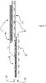
Figure 3 shows schematically the attachment of two adjacent laminates according to the invention -
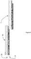
Figure 4 shows schematically an alternative embodiment of a laminate according to the invention -
Figure 5 shows schematically an example of a laminate with an alumimum foil according to the invention -
Figure 6 shows schematically a further example of a laminate with an alumimum foil according to the invention -
Figure 1 shows an example of a laminate (1) according to the invention. The laminate (1) has three layers, a top layer that is a spunbond (21), a middle layer that is an active film (25) and a bottom layer that is a woven fabric (11). The top and middle layer, i.e. the spunbond (21) and the film (25), form the active element (20) and the bottom layer, i.e. the woven fabric (11) forms the reinforcement element (10). The film may consist of or include different materials, such as PP, PE, PA, TPU, TPE. - In laminates that are to be used as outer breathable roofing membranes, i.e. above the rafters and/or the thermal insulation, the film may be microporous or monolithic. In laminates that are to be used as inner laminates, i.e. below the rafters and/or the thermal insulation, the film may be a vapour control layer.
- The strength of the woven fabric (11) provides an additional stiffness to the laminate (1) and enables an improved lay-down of the laminate (1) on horizontal or inclined, pitched, roofs so that the laminate (1) can be strongly pulled over the rafters, when the laminate (1) is used above the rafters.
- The width of the spunbond (21) and the active film (25) is larger than the width of the woven fabric (11), so that the laminate (1) has a very flexible and soft strip (60) that overhangs beyond the more rigid and stronger woven fabric (11). In some examples the width of the active element (20), i.e. the spunbond (21) and the film (25) is 2 cm to 15 cm larger, preferably 10 to 15 cm larger, than the width of the reinforcement element (10).
- The active element (20) of the overhanging strip (60) is covered at least partially over its width with an adhesive material, for example an adhesive tape (31) of pressure sensitive adhesive (PSA). The adjacent laminate has a further adhesive material (31) along a strip on the spunbond (21) that in use will be joint to the corresponding adhesive material (31) of the overhanging strip (60), as schematically is shown in
Figure 3 , by cold bonding, i.e. without requiring input of thermal energy. The adhesive material (31) may be protected by a liner not shown in the Figures before connecting the laminates (1) together. - As it illustrated in
Figure 3 , the adhesive material is applied on the film of the soft edge and on the top side of the spunbond of the adjacent laminate, so as to form a joint between a soft strip of one laminate and a strong strip of the other laminate. Bu attaching a soft strip to a relative harder strip, it is easy to avoid the wavy performance and the subsequent air-gaps between overlapping strips of adjacent laminates, such as those shown inFigure 2 . - In an alternative embodiment of the invention shown in
Figure 4 , the film (25) and the woven fabric (11) attached to it form an overhanging strip that extends beyond an edge of the spunbond (21). This strip of active film (25) and woven fabric (11) is much stronger than the overhanging strip (60), because it includes the woven fabric (11). Soft and flexible strip (60) is designated as a "soft edge" or "open edge". In the alternative embodiment ofFigure 4 , the adhesive material (31) is applied on the active film (25) rather than on the spunbond (21), a feature that provides a stronger and more durable joint between adjacent laminates, as the cohesion is effected between two active films (25). - The joint of a soft, more flexible, strip and a strong, less flexible, strip enables a complete adhesion of two laminates over the full area of the roof, so that gaps along the joints are avoided and the joints establish a watertight and airtight connection between the laminates. Such a connection may be achieved between two adjacent laminates either by providing the adhesion material on the active film of one laminate and on the spunbond on the other, as shown schematically in
Figure 3 , or by providing the adhesive material on the active film of both laminates, as schematically shown inFigure 4 . The laminate has a high tensile strength and provides high shear strength of the joint when two adjacent laminates are attached to each other. The joint of the adjacent laminates is air-tight and water tight, since there are no air gaps that damage the air- and water- tightness of the joint. Further, the strength under transverse loading is high and with a laminate of the invention the tensile strength exceeds 500 N per 5 cm of edge width of the laminate. Thus, damages and accidents are avoided, when during construction, the user steps on a laminate between the rafters of a roof. - Examples of the invention are described below:
- One example consists of three layers, a spunbond and an active film that make the active element and a woven fabric or a net, with the film being in between the spunbond and the woven fabric or net.
- In a further example the face of the woven fabric is also covered by a spunbond.
- When used towards the outside of the roof the reinforcement element (10) has a woven fabric (11) and the active element (20) has a monolithic film (25), for example of TPU or TPE or containing TPU or TPE. In use the laminate (1) is placed with the reinforcement element (10) below the active element (20), i.e. towards the interior of the building.
- In another example of a laminate (1) used towards the outside of the roof, the reinforcement element (10) has a woven fabric (11) and a further aluminum perforated or closed foil (40), which acts as a heat reflector, and the active element (20) has a microporous film (25) and a spunbond (21), for example of PP or PE or containing PP or PE. This example is schematically presented in
Figure 5 . In use the laminate (1) is placed with the reinforcement element (10) above the active element (20), i.e. facing the exterior of the building. - When used towards the inside the reinforcement element (10) has a woven fabric (11) and the active element (20) has a monolithic vapour control layer (25) and a spunbond (21) for protection. In use this laminate (1) is placed with the reinforcement element (10) above the active element, i.e. facing outside of the building.
- In another example of a laminate (1) used towards the inside, the reinforcement element (10) has a woven fabric (11) and a further aluminum perforated or closed foil (40), which acts a heat reflector and the active element (20) has a monolithic vapour control layer (25) and a spunbond (221 for protection. In use this laminate (1) is placed with the reinforcement element (10) below the active element (20), i.e. facing inside.
- In an alternative of the examples presented above, which include an aluminum foil (40), the aluminum foil (40) may be part of the active element (20) rather than of the reinforcement element (10), for example by attaching it to the spunbond (21). Such an example is schematically presented in
Figure 6 that shows a laminate with an aluminum foil (40), a spunbond (21), an active film (20) and a woven fabric (11). Alternatively a porous or continuous metallized film, preferably with aluminum, may be used instead of an aluminum foil. - In the previous examples and in some further examples the width of the laminate may be 100 cm to 300 cm and its weight 140 gr/m2 to 350 gr/m2 - not including the weight of the adhesive tape. The open edge, i.e. the overhanding strip (60) of the active element has a width of 2 cm to 20 cm, preferably between 10 cm and 20 cm and the adhesive tape has a width of equal of less than the width of the overhanging strip (60). The weight of the adhesion tape may be between 60 gr/m2 to 200 gr/m2.
- The various layers of a laminate, are attached to each other by methods known in the art.
- All the above embodiments are examples that do no limit the scope of the protection. Further examples are anticipated within the invention as it is defined in the independent claims.
Claims (15)
- Laminate (1) for insulation of roofs including a reinforcement element (10) and an active element (20), whereby active element (20) is more flexible rather than the reinforcement element (10) and the active element (20) has a strip (60) overhanging beyond an edge of the reinforcement element (10).
- Laminate (1) according to claim 1, whereby a strip of adhesive material, for example an adhesive tape (31), is provided along the overhanging strip (60) and to a face of the active element (20), which is in contact with the reinforcement element (10), which material (31) in use is to be further attached to an adjacent laminate (1).
- Laminate (1) according claim 1 or claim 2, whereby the tensile strength of the active element (20) is lower than the tensile strength of the reinforcement element (10).
- Laminate (1) according to any one of claims 1 to 3, whereby the reinforcement element (10) has a net or a woven fabric (11), preferably a woven fabric (11).
- Laminate (1) according to any one of claims 1 to 4, whereby the laminate includes one of i) a perforated aluminum foil (40), ii) a closed aluminum foil (40), iii) a perforated metallized film, iv) a closed metallized film, either in the active element (20) or in the reinforcement element (10).
- Laminate (1) according to any one of claims 1 to 5, whereby the active element (20) includes a water-tight monolithic breathable layer (25), preferably made of TPU or TPE or including TPU or TPE, or a water-tight microporous breathable layer (25).
- Laminate (1) according to any one of claims 1 to 6, whereby the active element (20) includes a vapour control layer (25) with variable permeability to controls the vapour transmission through it.
- Laminate (1) according to claim 7, whereby the vapour control layer (25) either contains or is made of one of the following materials: i) polypropylene (PP), ii) polyethylene (PE), iii) polyamide (PA), iv) thermoplastic polyurethane (TPU), v) thermoplastic elastomer (TPE).
- Laminate (1) according to any one of claims 1 to 8, whereby the active element (20) includes a spunbond layer (21) and an active film (25) and the reinforcement element (10) includes a woven fabric (11), whereby the film (25) is in-between the spunbond (21) and the woven fabric (11).
- Laminate (1) according to claim 9, with a further strip other than the strip (60) overhanging the reinforcement element (10), which further strip extends beyond an edge of the spunbond layer (21), includes a strip-portion of the active film (25) and a strip-portion the woven fabric (11) and whereby a strip of adhesive material (31), preferably an adhesive tape (31), is provided along the further strip on the active film (25).
- Method to attach two adjacent laminates, including the following steps:• bring in an overlapping disposition the two laminates so that a strip of one laminate contacts a strip of the other laminate, whereby the strip of one laminate is more flexible that the strip of the other laminate,• tighten the strip that has lower flexibility on the other strip• attach the two strips with an adhesive material.
- Method according to claim 13, whereby the more flexible strip (60) has a tensile strength that is lower than the tensile strength of the less flexible strip.
- Method according to claim 11 or claim 12, whereby each one of the two laminates (1) includes a reinforcement layer (11), a spunbond layer (21) and an active film (25) between the reinforcement layer (11) and the spunbond layer (21), whereby the more flexible strip (60) does not include any portion of the reinforcement layer (11).
- Method according to claim 13, whereby the adhesive material is applied to the active film (25) of one laminate (1) and the spunbond layer (11) or the active film (25) of the other laminate (1).
- Method according to any one of claims 11 to 14, whereby at least one of the two laminates, preferably both laminates, is/are according to any one of claims 1 to 14.
Applications Claiming Priority (1)
| Application Number | Priority Date | Filing Date | Title |
|---|---|---|---|
| GR20200100686A GR20200100686A (en) | 2020-11-18 | 2020-11-18 | Roof laminate with flexible edges |
Publications (3)
| Publication Number | Publication Date |
|---|---|
| EP4000915A1 true EP4000915A1 (en) | 2022-05-25 |
| EP4000915B1 EP4000915B1 (en) | 2024-11-13 |
| EP4000915C0 EP4000915C0 (en) | 2024-11-13 |
Family
ID=81214553
Family Applications (1)
| Application Number | Title | Priority Date | Filing Date |
|---|---|---|---|
| EP20217839.8A Active EP4000915B1 (en) | 2020-11-18 | 2020-12-30 | Roof laminate with flexible edges |
Country Status (2)
| Country | Link |
|---|---|
| EP (1) | EP4000915B1 (en) |
| GR (1) | GR20200100686A (en) |
Citations (6)
| Publication number | Priority date | Publication date | Assignee | Title |
|---|---|---|---|---|
| GB2080196A (en) * | 1980-06-16 | 1982-02-03 | Grace W R & Co | Self-adhesive roofing laminate having self-edge sealing properties |
| EP1715110A2 (en) * | 2005-04-21 | 2006-10-25 | Saint-Gobain Isover G+H Ag | Insulating mineral wool mat with an insulating layer for jamming between delimiting surfaces |
| US20060292328A1 (en) * | 2005-06-23 | 2006-12-28 | Nordenia Deutschland Gronau Gmbh | Laminate material web having elastic and non-elastic regions |
| EP2592196A1 (en) * | 2011-11-11 | 2013-05-15 | Caplast Kunststoffverarbeitungs GmbH | Waterproof roof underlay for a sloping roof |
| EP3002382A1 (en) * | 2014-10-02 | 2016-04-06 | Ewald Dörken AG | Roof underlay |
| EP3345755A1 (en) * | 2017-01-10 | 2018-07-11 | Thrace Nonwovens & Geosynthetics S.A. | Heat reflecting vapour control laminate with variable water vapour diffusion |
-
2020
- 2020-11-18 GR GR20200100686A patent/GR20200100686A/en unknown
- 2020-12-30 EP EP20217839.8A patent/EP4000915B1/en active Active
Patent Citations (6)
| Publication number | Priority date | Publication date | Assignee | Title |
|---|---|---|---|---|
| GB2080196A (en) * | 1980-06-16 | 1982-02-03 | Grace W R & Co | Self-adhesive roofing laminate having self-edge sealing properties |
| EP1715110A2 (en) * | 2005-04-21 | 2006-10-25 | Saint-Gobain Isover G+H Ag | Insulating mineral wool mat with an insulating layer for jamming between delimiting surfaces |
| US20060292328A1 (en) * | 2005-06-23 | 2006-12-28 | Nordenia Deutschland Gronau Gmbh | Laminate material web having elastic and non-elastic regions |
| EP2592196A1 (en) * | 2011-11-11 | 2013-05-15 | Caplast Kunststoffverarbeitungs GmbH | Waterproof roof underlay for a sloping roof |
| EP3002382A1 (en) * | 2014-10-02 | 2016-04-06 | Ewald Dörken AG | Roof underlay |
| EP3345755A1 (en) * | 2017-01-10 | 2018-07-11 | Thrace Nonwovens & Geosynthetics S.A. | Heat reflecting vapour control laminate with variable water vapour diffusion |
Also Published As
| Publication number | Publication date |
|---|---|
| EP4000915B1 (en) | 2024-11-13 |
| EP4000915C0 (en) | 2024-11-13 |
| GR20200100686A (en) | 2022-06-08 |
Similar Documents
| Publication | Publication Date | Title |
|---|---|---|
| US4493175A (en) | Roofing system | |
| CA2858321C (en) | Thermoplastic single ply protective covering | |
| US4712348A (en) | Non-penetrating roof system | |
| US11407209B2 (en) | Protective packaging membranes as integrated layer in building system components | |
| KR101553393B1 (en) | Self adhesive combination waterproofing sheet, the overlapping connection structure using the self adhesive combination waterproofing sheet and the method thereof | |
| EP3345757B1 (en) | Advanced multilayer breathable roofing laminate | |
| EP4000915B1 (en) | Roof laminate with flexible edges | |
| CN204566813U (en) | Composite and flexible flashing band | |
| CN204475542U (en) | Waterproof waterproof cloth | |
| WO1996025569A1 (en) | Moisture-permeable composite sheet for water-proofing concrete | |
| CN104652619A (en) | Waterproof and rainproof cloth | |
| CN104674957B (en) | Waterproof cloth and anti-seepage node for doors and windows fabricated by waterproof cloth | |
| GB2253184A (en) | Unitary insulating and weatherproofing article for use on the exterior of buildings | |
| EP2623685A1 (en) | Insulating and waterproofing membrane | |
| JP3340023B2 (en) | Composite tarpaulin for construction and civil engineering | |
| DK153899B (en) | INSULATING ROOF COVER. | |
| CN204570946U (en) | The door and window percolation-proof node of waterproof waterproof cloth and making thereof | |
| JP7469836B1 (en) | Breathable and waterproof building sheet | |
| US12215503B2 (en) | Roofing material, and roof system including the roofing material | |
| WO2025198470A1 (en) | Roofing sheet, roll, roof and method for covering a roof structure using the roofing sheet | |
| JP2762039B2 (en) | How to join the impermeable sheet | |
| DK2243888T3 (en) | Moisture Protection System træstander- or roofs with rafters | |
| JPS6123388Y2 (en) | ||
| JP2515537Y2 (en) | Heat storage tank | |
| EP1728621B1 (en) | Laminate against alkaline salts/moisture and structural subsidences in buildings |
Legal Events
| Date | Code | Title | Description |
|---|---|---|---|
| PUAI | Public reference made under article 153(3) epc to a published international application that has entered the european phase |
Free format text: ORIGINAL CODE: 0009012 |
|
| STAA | Information on the status of an ep patent application or granted ep patent |
Free format text: STATUS: THE APPLICATION HAS BEEN PUBLISHED |
|
| AK | Designated contracting states |
Kind code of ref document: A1 Designated state(s): AL AT BE BG CH CY CZ DE DK EE ES FI FR GB GR HR HU IE IS IT LI LT LU LV MC MK MT NL NO PL PT RO RS SE SI SK SM TR |
|
| STAA | Information on the status of an ep patent application or granted ep patent |
Free format text: STATUS: REQUEST FOR EXAMINATION WAS MADE |
|
| 17P | Request for examination filed |
Effective date: 20221118 |
|
| RBV | Designated contracting states (corrected) |
Designated state(s): AL AT BE BG CH CY CZ DE DK EE ES FI FR GB GR HR HU IE IS IT LI LT LU LV MC MK MT NL NO PL PT RO RS SE SI SK SM TR |
|
| STAA | Information on the status of an ep patent application or granted ep patent |
Free format text: STATUS: EXAMINATION IS IN PROGRESS |
|
| 17Q | First examination report despatched |
Effective date: 20240102 |
|
| GRAP | Despatch of communication of intention to grant a patent |
Free format text: ORIGINAL CODE: EPIDOSNIGR1 |
|
| STAA | Information on the status of an ep patent application or granted ep patent |
Free format text: STATUS: GRANT OF PATENT IS INTENDED |
|
| INTG | Intention to grant announced |
Effective date: 20240704 |
|
| GRAS | Grant fee paid |
Free format text: ORIGINAL CODE: EPIDOSNIGR3 |
|
| GRAA | (expected) grant |
Free format text: ORIGINAL CODE: 0009210 |
|
| STAA | Information on the status of an ep patent application or granted ep patent |
Free format text: STATUS: THE PATENT HAS BEEN GRANTED |
|
| AK | Designated contracting states |
Kind code of ref document: B1 Designated state(s): AL AT BE BG CH CY CZ DE DK EE ES FI FR GB GR HR HU IE IS IT LI LT LU LV MC MK MT NL NO PL PT RO RS SE SI SK SM TR |
|
| REG | Reference to a national code |
Ref country code: GB Ref legal event code: FG4D |
|
| REG | Reference to a national code |
Ref country code: CH Ref legal event code: EP |
|
| REG | Reference to a national code |
Ref country code: IE Ref legal event code: FG4D |
|
| REG | Reference to a national code |
Ref country code: DE Ref legal event code: R096 Ref document number: 602020041233 Country of ref document: DE |
|
| U01 | Request for unitary effect filed |
Effective date: 20241204 |
|
| U07 | Unitary effect registered |
Designated state(s): AT BE BG DE DK EE FI FR IT LT LU LV MT NL PT RO SE SI Effective date: 20241220 |
|
| U20 | Renewal fee for the european patent with unitary effect paid |
Year of fee payment: 5 Effective date: 20250214 |
|
| PG25 | Lapsed in a contracting state [announced via postgrant information from national office to epo] |
Ref country code: HR Free format text: LAPSE BECAUSE OF FAILURE TO SUBMIT A TRANSLATION OF THE DESCRIPTION OR TO PAY THE FEE WITHIN THE PRESCRIBED TIME-LIMIT Effective date: 20241113 Ref country code: IS Free format text: LAPSE BECAUSE OF FAILURE TO SUBMIT A TRANSLATION OF THE DESCRIPTION OR TO PAY THE FEE WITHIN THE PRESCRIBED TIME-LIMIT Effective date: 20250313 |
|
| PG25 | Lapsed in a contracting state [announced via postgrant information from national office to epo] |
Ref country code: ES Free format text: LAPSE BECAUSE OF FAILURE TO SUBMIT A TRANSLATION OF THE DESCRIPTION OR TO PAY THE FEE WITHIN THE PRESCRIBED TIME-LIMIT Effective date: 20241113 |
|
| PG25 | Lapsed in a contracting state [announced via postgrant information from national office to epo] |
Ref country code: NO Free format text: LAPSE BECAUSE OF FAILURE TO SUBMIT A TRANSLATION OF THE DESCRIPTION OR TO PAY THE FEE WITHIN THE PRESCRIBED TIME-LIMIT Effective date: 20250213 |
|
| PG25 | Lapsed in a contracting state [announced via postgrant information from national office to epo] |
Ref country code: GR Free format text: LAPSE BECAUSE OF FAILURE TO SUBMIT A TRANSLATION OF THE DESCRIPTION OR TO PAY THE FEE WITHIN THE PRESCRIBED TIME-LIMIT Effective date: 20250214 |
|
| PG25 | Lapsed in a contracting state [announced via postgrant information from national office to epo] |
Ref country code: PL Free format text: LAPSE BECAUSE OF FAILURE TO SUBMIT A TRANSLATION OF THE DESCRIPTION OR TO PAY THE FEE WITHIN THE PRESCRIBED TIME-LIMIT Effective date: 20241113 |
|
| PG25 | Lapsed in a contracting state [announced via postgrant information from national office to epo] |
Ref country code: RS Free format text: LAPSE BECAUSE OF FAILURE TO SUBMIT A TRANSLATION OF THE DESCRIPTION OR TO PAY THE FEE WITHIN THE PRESCRIBED TIME-LIMIT Effective date: 20250213 |
|
| PG25 | Lapsed in a contracting state [announced via postgrant information from national office to epo] |
Ref country code: SM Free format text: LAPSE BECAUSE OF FAILURE TO SUBMIT A TRANSLATION OF THE DESCRIPTION OR TO PAY THE FEE WITHIN THE PRESCRIBED TIME-LIMIT Effective date: 20241113 |
|
| PG25 | Lapsed in a contracting state [announced via postgrant information from national office to epo] |
Ref country code: SK Free format text: LAPSE BECAUSE OF FAILURE TO SUBMIT A TRANSLATION OF THE DESCRIPTION OR TO PAY THE FEE WITHIN THE PRESCRIBED TIME-LIMIT Effective date: 20241113 |
|
| PG25 | Lapsed in a contracting state [announced via postgrant information from national office to epo] |
Ref country code: CZ Free format text: LAPSE BECAUSE OF FAILURE TO SUBMIT A TRANSLATION OF THE DESCRIPTION OR TO PAY THE FEE WITHIN THE PRESCRIBED TIME-LIMIT Effective date: 20241113 |
|
| REG | Reference to a national code |
Ref country code: CH Ref legal event code: PL |
|
| PG25 | Lapsed in a contracting state [announced via postgrant information from national office to epo] |
Ref country code: MC Free format text: LAPSE BECAUSE OF FAILURE TO SUBMIT A TRANSLATION OF THE DESCRIPTION OR TO PAY THE FEE WITHIN THE PRESCRIBED TIME-LIMIT Effective date: 20241113 |
|
| PLBE | No opposition filed within time limit |
Free format text: ORIGINAL CODE: 0009261 |
|
| STAA | Information on the status of an ep patent application or granted ep patent |
Free format text: STATUS: NO OPPOSITION FILED WITHIN TIME LIMIT |
|
| PG25 | Lapsed in a contracting state [announced via postgrant information from national office to epo] |
Ref country code: CH Free format text: LAPSE BECAUSE OF NON-PAYMENT OF DUE FEES Effective date: 20241231 |
|
| 26N | No opposition filed |
Effective date: 20250814 |
|
| PG25 | Lapsed in a contracting state [announced via postgrant information from national office to epo] |
Ref country code: IE Free format text: LAPSE BECAUSE OF NON-PAYMENT OF DUE FEES Effective date: 20241230 |
|
| GBPC | Gb: european patent ceased through non-payment of renewal fee |
Effective date: 20250213 |
|
| U20 | Renewal fee for the european patent with unitary effect paid |
Year of fee payment: 6 Effective date: 20251126 |
|
| PG25 | Lapsed in a contracting state [announced via postgrant information from national office to epo] |
Ref country code: GB Free format text: LAPSE BECAUSE OF NON-PAYMENT OF DUE FEES Effective date: 20250213 |