EP4000848A1 - Foaming method and apparatus - Google Patents
Foaming method and apparatus Download PDFInfo
- Publication number
- EP4000848A1 EP4000848A1 EP21208302.6A EP21208302A EP4000848A1 EP 4000848 A1 EP4000848 A1 EP 4000848A1 EP 21208302 A EP21208302 A EP 21208302A EP 4000848 A1 EP4000848 A1 EP 4000848A1
- Authority
- EP
- European Patent Office
- Prior art keywords
- unit
- modular
- modular moulding
- drum unit
- rolling means
- Prior art date
- Legal status (The legal status is an assumption and is not a legal conclusion. Google has not performed a legal analysis and makes no representation as to the accuracy of the status listed.)
- Granted
Links
Images






Classifications
-
- B—PERFORMING OPERATIONS; TRANSPORTING
- B29—WORKING OF PLASTICS; WORKING OF SUBSTANCES IN A PLASTIC STATE IN GENERAL
- B29C—SHAPING OR JOINING OF PLASTICS; SHAPING OF MATERIAL IN A PLASTIC STATE, NOT OTHERWISE PROVIDED FOR; AFTER-TREATMENT OF THE SHAPED PRODUCTS, e.g. REPAIRING
- B29C44/00—Shaping by internal pressure generated in the material, e.g. swelling or foaming ; Producing porous or cellular expanded plastics articles
- B29C44/02—Shaping by internal pressure generated in the material, e.g. swelling or foaming ; Producing porous or cellular expanded plastics articles for articles of definite length, i.e. discrete articles
- B29C44/12—Incorporating or moulding on preformed parts, e.g. inserts or reinforcements
- B29C44/14—Incorporating or moulding on preformed parts, e.g. inserts or reinforcements the preformed part being a lining
-
- B—PERFORMING OPERATIONS; TRANSPORTING
- B29—WORKING OF PLASTICS; WORKING OF SUBSTANCES IN A PLASTIC STATE IN GENERAL
- B29C—SHAPING OR JOINING OF PLASTICS; SHAPING OF MATERIAL IN A PLASTIC STATE, NOT OTHERWISE PROVIDED FOR; AFTER-TREATMENT OF THE SHAPED PRODUCTS, e.g. REPAIRING
- B29C31/00—Handling, e.g. feeding of the material to be shaped, storage of plastics material before moulding; Automation, i.e. automated handling lines in plastics processing plants, e.g. using manipulators or robots
- B29C31/006—Handling moulds, e.g. between a mould store and a moulding machine
-
- B—PERFORMING OPERATIONS; TRANSPORTING
- B29—WORKING OF PLASTICS; WORKING OF SUBSTANCES IN A PLASTIC STATE IN GENERAL
- B29C—SHAPING OR JOINING OF PLASTICS; SHAPING OF MATERIAL IN A PLASTIC STATE, NOT OTHERWISE PROVIDED FOR; AFTER-TREATMENT OF THE SHAPED PRODUCTS, e.g. REPAIRING
- B29C44/00—Shaping by internal pressure generated in the material, e.g. swelling or foaming ; Producing porous or cellular expanded plastics articles
- B29C44/34—Auxiliary operations
- B29C44/36—Feeding the material to be shaped
- B29C44/38—Feeding the material to be shaped into a closed space, i.e. to make articles of definite length
- B29C44/42—Feeding the material to be shaped into a closed space, i.e. to make articles of definite length using pressure difference, e.g. by injection or by vacuum
- B29C44/428—Mould constructions; Mould supporting equipment
-
- B—PERFORMING OPERATIONS; TRANSPORTING
- B29—WORKING OF PLASTICS; WORKING OF SUBSTANCES IN A PLASTIC STATE IN GENERAL
- B29C—SHAPING OR JOINING OF PLASTICS; SHAPING OF MATERIAL IN A PLASTIC STATE, NOT OTHERWISE PROVIDED FOR; AFTER-TREATMENT OF THE SHAPED PRODUCTS, e.g. REPAIRING
- B29C44/00—Shaping by internal pressure generated in the material, e.g. swelling or foaming ; Producing porous or cellular expanded plastics articles
- B29C44/34—Auxiliary operations
- B29C44/58—Moulds
-
- B—PERFORMING OPERATIONS; TRANSPORTING
- B29—WORKING OF PLASTICS; WORKING OF SUBSTANCES IN A PLASTIC STATE IN GENERAL
- B29K—INDEXING SCHEME ASSOCIATED WITH SUBCLASSES B29B, B29C OR B29D, RELATING TO MOULDING MATERIALS OR TO MATERIALS FOR MOULDS, REINFORCEMENTS, FILLERS OR PREFORMED PARTS, e.g. INSERTS
- B29K2075/00—Use of PU, i.e. polyureas or polyurethanes or derivatives thereof, as moulding material
-
- B—PERFORMING OPERATIONS; TRANSPORTING
- B29—WORKING OF PLASTICS; WORKING OF SUBSTANCES IN A PLASTIC STATE IN GENERAL
- B29L—INDEXING SCHEME ASSOCIATED WITH SUBCLASS B29C, RELATING TO PARTICULAR ARTICLES
- B29L2031/00—Other particular articles
- B29L2031/762—Household appliances
- B29L2031/7622—Refrigerators
Definitions
- This invention relates to a method and an apparatus for simultaneous foaming of objects, such as doors for a refrigerator, for a display bench, for a building or the like, and, in general, panels or objects, mostly substantially two-dimensional, i.e. having two dimensions that prevail over a third dimension, and provided with outer coating elements, such as half shells or shaped panels made of plastics, metal or slabs or sheets that are flat, curved or grooved between which coating elements a thermally insulating intermediate layer has to be placed that is made of polyurethane or phenol material.
- a first technology is based on conveying doors by a plant that has a drum that is rotatable around a horizontal rotation axis.
- each mould-holder press comprising two upper and lower flat containing surfaces, suitable for being positioned according to respective horizontal planes and parallel to one another, and the distance of which planes from one another is variable.
- a mould-holder press is provided for each pair of coupled half moulds.
- the mould-holder presses are then mounted on the drum carousel, are rotated integrally with the latter and are each driven by a dedicated drive device to move the aforesaid containing and pressing surfaces towards and away from one another.
- the lower and upper half moulds are coupled with the aforesaid containing or pressing surfaces acting to contrast the foam that, expanding inside the mould, exerts very high pressure until values of 6 - 8 Newton per square centimetre are reached.
- respective half moulds are thus fixed that support and maintain in position the respective half-shells or shaped panels intended to define the outer face and the inner face of the door of the refrigerator.
- An operator is assigned to loading the outer face half shell of the door onto the upper half shell and the inner face half shell (e.g. a thermoformed element made of plastics) onto the lower half mould, after which the drum carousel is rotated in an indexed manner.
- the inner face half shell e.g. a thermoformed element made of plastics
- the foamed door In the zone dedicated to the operator, the foamed door is unloaded and the half shells or housings are unloaded to foam the doors to be formed.
- the injection of the polyurethane mixture and the polymerization step of the foam can then occur whilst the drum carousel rotates by successive steps.
- the aforesaid traditional drum plant has some limits.
- the multiplicity of mould-holder presses with the respective drive devices leads to great structural and functional complexity that entails, from the dynamic point of view, significant inertia masses that set functional and productive limits on the entire plant.
- a second technology provides conveying of the doors by a plant equipped with a dual chain conveying device, the so-called “paternoster”.
- the dual chain conveyor belt is shaped to support and draw a plurality of mould holders, each of which contains a pair of half moulds for foaming a door for a refrigerator.
- the mould holders advance maintaining a horizontal lie by complex mechanical coupling systems for coupling the chain elements with the respective drive pinions.
- complex mechanical coupling systems for coupling the chain elements with the respective drive pinions.
- Both the drum plant and the "paternoster” plant described above have limits: in order to satisfy the increasingly strict demands of refrigerator manufacturers, which set increasing quality levels with containment of geometric strains on the shells below increasingly strict acceptability thresholds, the aforesaid plants must be structured in a very heavy and robust manner.
- One object of the present invention is to improve current systems for foaming doors, in particular doors of refrigerators or, more general, of substantially two-dimensional objects. Another object is to improve current foaming plants, by increasing the versatility and productive capacity thereof.
- a further object is to simplify foaming plants both structurally and functionally.
- one object is to provide a solution that successfully meets current needs of the refrigerator manufacturing industry in which there is an increasingly marked tendency to diversify the various models, varying the aesthetic and geometric appearance thereof, the dimensions and combination between lower and upper doors, thus making necessary a continuous increase of the various geometric configurations of the containing moulds dedicated to the manufacture of the different geometric shapes of doors.
- One object of the present invention is thus to provide a solution for foaming doors of refrigerators that is able to adapt in real time ( “just in time” ) to the various desired geometric shapes, fulfilling each time the sequence of orders coming from the market.
- the method and the apparatus according to the invention enable the objects mentioned previously to be achieved.
- the apparatus according to the proposed solution is significantly simplified from the structural point of view as there is no need to provide the mould-holder presses and the connected devices for lifting/lowering or driving the presses.
- the first and second rolling means arranged at a set reciprocal distance to define the housing cells perform effectively clamping and maintenance without the need for complex and costly drive systems and clamping devices provided with specific and expensive mechanisms and articulated joints.
- an apparatus 1 for foaming substantially two-dimensional objects, i.e. having two dimensions that are much greater than a third dimension.
- the apparatus 1 (and the corresponding foaming method) is particularly suitable for foaming doors or pairs of doors 2 for refrigerators of domestic or industrial type, or also for foaming door-lids for chest freezers, insulating panels for display benches, doors and windows for houses and buildings and other products.
- the objects 2 to be foamed by the apparatus 1 are provided with outer coating elements 3, 3', such as half-shells or shaped panels made of plastics, metal or slabs or sheets that are flat, curved, or shaped by thermoforming, coupled for shaping a hollow box possibly having a circumferential seal between which foaming occurs to generate an intermediate layer 6 made of thermally insulating phenol or polyurethane material.
- outer coating elements 3, 3' such as half-shells or shaped panels made of plastics, metal or slabs or sheets that are flat, curved, or shaped by thermoforming, coupled for shaping a hollow box possibly having a circumferential seal between which foaming occurs to generate an intermediate layer 6 made of thermally insulating phenol or polyurethane material.
- a plurality of modular moulding units 4 is included, each consisting of a first half mould 5A and of a second half mould 5B that are mutually couplable/uncouplable, that are suitable for receiving respective coating elements 3, 3' intended to define the outer surfaces of the corresponding objects 2 to be obtained.
- first half mould 5A and the second half mould 5B are fitted removably to respective reinforcing modular superstructures 50A, 50B.
- a support pallet 14A, 14B can be interposed that permits rapid and easy replacement of the half moulds 5A, 5B without also having to extract the reinforcing superstructures 50A, 50B.
- the reinforcing superstructures 50A, 50B include centring and coupling elements 51A, 51B (male elements and female elements), suitable for ensuring correct positioning and reciprocal coupling of the reinforcing superstructures 50A, 50B in the closed configuration of the modular moulding unit 4.
- centring and coupling elements 51A, 51B are for example of the taper pin (male element) type that engages a respective slot (female element).
- the modular moulding units 4 consist only of the two half moulds 5A, 5B, the aforementioned reinforcing superstructures (understood as distinct elements) being absent.
- the half moulds 5A, 5B are shaped and sized in a very robust structural manner, so as to be able to support effectively the stress imparted by the mixture and the contrasting actions exerted by the pressing rollers 7, 8.
- the apparatus 1 comprises a rotatable drum unit 9, configured for storing the modular moulding units 4 and advancing along at least part of a closed advancement path P along which polymerization and shape stabilization process occurs for the foamed objects 2.
- the apparatus comprises a containing chamber 15 provided with a thermostating system inside which the drum unit 9 is housed.
- the containing chamber 15, in particular, comprises a hot air kiln and is configured for subjecting the modular moulding units 4, advancing along the advancement path P, to a heating step to promote the polymerization process della chemically reactive mixture.
- the rotatable drum unit 9 is rotatable around a horizontal rotation axis A2 and is configured for receiving the modular moulding units 4 with the greater dimensions thereof oriented longitudinally parallel to said rotation axis A2.
- first rolling means 7 that are further than the rotation axis A2
- second rolling means 8 placed at a shorter distance from the rotation axis A2 than the first rolling means 7.
- the first 7 and second 8 rolling means are arranged for inserting, positioning and maintaining modular moulding units 4 in a clamped condition on the drum unit 9.
- first 7 and second 8 rolling means ensure stable closure and clamping of the half moulds 5A, 5B that are in reciprocal contact without having to use bolts, padlocks or similar devices to keep the single modular moulding units 4 closed.
- the action of clamping and maintaining in a closed position the modular moulding units 4 is achieved by applying opposing pressure actions that are exerted by the aforesaid first 7 and second 8 rolling means that come into contact on opposite sides on each modular moulding unit 4.
- the first rolling means 7 and the second rolling means 8 comprise respectively first pressing rollers 7 and second pressing rollers 8 arranged at a reciprocal operating distance D so as to define, on the rotatable drum unit 9, a plurality of housing cells C1, ..., Cn or housing cubicles intended for receiving the same number of respective modular moulding units 4. Inserting and extracting a modular moulding unit 4 into and from a housing cell C1, ..., Cn is possible through a transit opening 30 obtained in the containing chamber 15. In particular, the transit opening 30 is obtained at a height corresponding to the lowest position that each housing C1, ..., Cn can adopt in the rotation of the drum unit 9.
- the first pressing rollers 7 and the second pressing rollers 8 are mutually spaced apart and arranged to exert on the opposite faces of each modular moulding unit 4 opposite pressure and clamping actions to contrast from the exterior the thrusts exerted by the expanding foam inside the modular moulding unit 4.
- the modular moulding units 4 can be adapted to the gap (size in section) of the housing cell C, i.e. to the operating distance D between the first pressing rollers 7 and the second pressing rollers 8, owing to the aforementioned support pallets 14A, 14B.
- the pallets 14A, 14B in addition to permitting rapid and easy replacement of the half moulds 5A, 5B, also enable the thickness of the two coupled half moulds and of the corresponding support and reinforcing structures 50A and 50B to be adapted to the aforesaid operating distance D.
- the first pressing rollers 7 and the second pressing rollers 8 are idling rollers, i.e. fitted in a freely rotatable manner to the drum unit 9.
- the first pressing rollers 7 and the second pressing rollers 8 are motor-driven rollers that are drivable to perform respectively the insertion and expulsion of each modular moulding unit 4 into/from the corresponding housing cell C1, ..., Cn obtained on the drum unit 9.
- all the first pressing rollers 7 of a series and all the second pressing rollers 8 of a second series 8 are driven by a single shared motion-transmission element 19 that can comprise a belt, a chain, or other equivalent mechanical transmission means.
- first rolling means 7 and the second rolling means 8 comprise rollers configured with a convex profile to adapt to deflecting actions.
- the first rolling means 7 and the second rolling means 8 comprise rollers configured with a coating made of an elastic material such as rubber to exert a better distributed action on said drum unit 9.
- the first rolling means 7 and the second rolling means 8 comprise rollers configured with circumferential slots distributed to exert concentrated actions in strengthened parts of the mould.
- the transmission element 19 is wound alternatingly along a path of the "zig-zag" first on a roller of one series and subsequently on a corresponding conjugated roller of the other series of pressing rollers and is moved by a respective motor 20, for example an electric motor.
- the motor-driven pressing rollers 7, 8, in addition to performing the function of positioning and maintaining the modular moulding units 4 in a well-closed position, also perform the function of promoting the insertion and expulsion of the moulding units 4 into/from the drum unit 9 simply, fast and precisely.
- the apparatus 1 further comprises a service and transfer carousel 10 placed in a position adjacent to the drum unit 9 and rotatable around a vertical axis A1.
- a service zone-station I entering/exiting the drum unit 9
- a service zone-station II are defined, for the preparing and loading operations.
- the service and transfer carousel 10 comprises a support plane 23 divided into two parts 23A, 23B, intended to simultaneously receive each of the respective modular moulding units 4 placed on sides opposite the vertical axis A1: precisely, a modular moulding unit 4 that has to be subjected, in a service zone Zs, to preparing and loading operations, and a modular moulding unit 4 that is already ready for foaming (in open mould or in closed mould configuration) are supported simultaneously, the modular moulding unit 4 that is already ready for foaming is intended, once closed, to be loaded onto the drum unit 9 in the appropriate housing shell Cn.
- Each part 23A, 23B, of the support plane is further tilted, by a toothed coupling and reduction gear 29, around a horizontal axis so as to vary the lying plane thereof. In this manner, it is possible to tilt a half mould in the service zone Zs, thus facilitating and making more ergonomic the operations for a possible operator.
- the support plane 23 is rotated around the vertical axis A1 owing to the presence of toothed coupling 27 connected to a drive motor 28.
- the service and transfer carousel 10 is thus configured for enabling - in the aforesaid service zone Zs - operations of preparing, loading with subsequent closing and insertion of the modular moulding units 4 on the drum unit 9.
- the service and transfer carousel 10 is configured for the operations of removing the modular moulding units 4 from the drum unit 9 and for the subsequent operations of opening and removing the foamed objects 2 from the modular moulding units 4.
- the service and transfer carousel 10 is rotatable by 180°, in opposite rotation directions and in an alternating manner, around the vertical axis A1 to transfer a modular moulding unit 4 that has just been prepared from the aforesaid service zone Zs to a proximity position for insertion into the drum unit 9 and for transferring a modular moulding unit 4 - containing the foamed object 2 and removed from the drum unit 9 - again to the service zone Zs to enable the object 2 that has just been obtained to be removed and to make new preparing and loading operations possible.
- the operations of removing finished objects 2 and the operations of preparing and loading moulding units are performed manually, by an operator O operating near the service zone Zs.
- the apparatus comprises a handling device configured for removing, in an automated manner, the finished objects 2 and for loading and positioning in the open half moulds 5A, 5B new coating elements 3, 3' or shells and/or inserts to be foamed.
- a handling device configured for removing, in an automated manner, the finished objects 2 and for loading and positioning in the open half moulds 5A, 5B new coating elements 3, 3' or shells and/or inserts to be foamed.
- two taking members 13A, 13B of the suction or gripper or equivalent type are provided that are configured for coupling/uncoupling the first half mould 5A from the respective half mould 5B to open and close each modular moulding unit 4.
- the two taking members 13 are arranged so as to be able to each operate on a respective parte 23A and part 23B of the support plane 23.
- the service and transfer carousel 10 comprises a stationary crosspiece 21 placed at a certain height and supported by a vertical upright 25, to which two motors 22 are fitted to move the respective taking members 13A and 13B.
- Each taking member 13 is supported by a rack 24 that engages a toothed wheel mechanism driven by a respective motor 22, or reduction gear, so as to be able to move vertically. In this manner, the taking member 13 can be raised or lowered to uncouple/couple a half mould from/with the other half mould.
- the parts 23A and 23B of the support plane 23 that is included in the service and transfer carousel 10 comprise support rollers 16 for the modular moulding units 4 and which enable a modular moulding unit 4 to slide when it has to be loaded onto the drum unit 9.
- the rollers 16 of the support plane 23, in one embodiment, are idling rollers.
- a pushing and pulling device 12 is provided that is configured for inserting removing a modular moulding unit 4 into/from, the respective housing cell C1, ..., Cn of the drum unit 9.
- the pushing and pulling device 12, that can be for example of the pneumatic or hydraulic cylinder type or be electrically driven, acts to push/pull a modular moulding unit 4, sliding the modular moulding unit 4 on the roller plane 16 indicated above that is obtained on the service and transfer carousel 10.
- a further roller plane 17 can be interposed between the service and transfer carousel 10 and the drum unit 9, to facilitate the sliding transit and transfer of the modular moulding units 4 from the service carousel 10 to the drum unit 9 and vice versa.
- the further roller plane 17 is also used to enable a suitable spacing to be set between the service and transfer carousel 10 and the drum unit 9, for example in order to facilitate possible maintenance tasks or for other needs.
- rollers 16 of the support plane 23 are motor-driven and are driven by a motor 26.
- the rollers 16 can intervene to translate the modular moulding unit 4 with respect to the drum unit 9, to replace or assist the aforesaid pushing and pulling device 12.
- a foaming station Fs is included that is located outside the drum unit 9 and in a position adjacent to the service and transfer carousel 10.
- the foaming station Fs includes one or more mixing heads 11 configured for dispensing the chemically reactive mixture in "open mould” mode on an open modular moulding unit 4 or operating in "closed mould” mode, i.e. to inject the mixture inside the closed modular moulding units 4.
- the mixing head/s 11 can be moved by suitable actuators of hydraulic or electric type etc. to be moved by sliding on suitable guides to near the modular moulding unit 4 before dispensing the reactive mixture.
- the foaming station is placed on the drum unit 9 and has one or more mixing heads positioned to operate directly on the modular moulding units 4 inserted on the drum unit 9.
- the mixing head/s 11 are configured for injecting the chemically reactive mixture - in "closed mould' mode - through the suitable injection holes made in the closed modular moulding units 4 containing the objects to be foamed.
- the apparatus 1 is provided with a mould-changing station W (schematized in Figure 2 ) arranged for enabling one or more modular moulding units 4 to be replaced or only a first half mould 5A and or a second half mould 5B with others of different size/geometry without the need to interrupt the advancement and process of the remaining modular moulding units 4.
- a mould-changing station W (schematized in Figure 2 ) arranged for enabling one or more modular moulding units 4 to be replaced or only a first half mould 5A and or a second half mould 5B with others of different size/geometry without the need to interrupt the advancement and process of the remaining modular moulding units 4.
- the mould-changing station W in particular, comprises a roller plane suitable for receiving a modular moulding unit 4 on which it is desired to make the change size.
- the mould-changing station W is placed in the vicinity of the service and transfer carousel 10, for example near the zone-station II. Nevertheless, it is possible to choose to arrange the mould-changing station in other desired zones.
- a mould-changing station W' can be provided that is placed on an opposite side of the drum unit 9 with respect to the service and transfer carousel 10 alternatively to or in combination with the mould-changing station W that has just been mentioned.
- the mould-changing station W' can also act as a station for initializing the foaming process, i.e. for the initial and transitory loading operations of all the modular moulding units 4 on the drum unit 9.
- the apparatus 1 comprises a control unit CU configured for rotating in an indexed manner the drum unit 9 and for synchronizing the sequential operations of removing the modular moulding units 4 from the drum unit 9, opening and removing the foamed object 2 and loading respective coating elements 3, 3' and possible inserts intended for the subsequent foaming and conveying step, along the advancement path P on the drum unit 9.
- a control unit CU configured for rotating in an indexed manner the drum unit 9 and for synchronizing the sequential operations of removing the modular moulding units 4 from the drum unit 9, opening and removing the foamed object 2 and loading respective coating elements 3, 3' and possible inserts intended for the subsequent foaming and conveying step, along the advancement path P on the drum unit 9.
- a possible operating sequence that is actuatable with the apparatus 1 involves, with reference to the zone-station I and to the zone-station II, the following operations:
- a first modular moulding unit 4 is extracted that is transferred to the service and transfer carousel 10, in a closed condition, on the positioned part 23 near the foaming zone Fs, i.e. in the zone-station I (for example on the part 23B of the carousel 10, as visible in Figures 2 and 7 ).
- the service and transfer carousel 10 rotates to bring and open the aforesaid first modular moulding unit 4 in the service zone Zs.
- the carousel 10 can open the modular moulding unit 4 during rotation, so that the latter reaches the service zone Zs that is already in open configuration.
- the aforesaid rotation takes a previous modular moulding unit 4 that is already loaded from the zone-station II to the zone-station I, at the foaming station Fs where it can be closed preventively (in the case of "closed mould' foaming), or can first receive the mixture (foamed in "open mould” ) and is subsequently reclosed and transferred immediately to the housing cell C1 of the drum that remained empty.
- the drum unit 9 then rotates by one step and takes a second modular moulding unit 4 to the extraction position where it is transferred from a housing cell C2 to part 23 B (zone-station I) of the carousel 10 and the cycle is repeated.
- an operator O extracts - from said first open modular moulding unit 4 placed on the carousel 10 - the foamed door 2, after which he positions the new coating elements 3, 3' to be sent to a subsequent foaming cycle.
- the carousel 10 Upon termination of the preparing and loading operations, the carousel 10 rotates by 180 degrees to move said first modular moulding unit 4 to the foaming zone Fs.
- the rotation thus takes the first modular moulding unit 4 - supported by the part 23 A - to the zone-station I near the foaming station Fs and the second modular moulding unit 4 - supported by the part 23 B - opposite the service zone Zs (zone-station II).
- the foaming station Fs intervenes to dispense the mixture.
- the mixture is dispensed in "open mould” or also in “closed mould” mode - after the half moulds 5A, 5B have been reciprocally closed preliminarily by the corresponding taking member 13.
- the first modular moulding unit 4 housed on the part 23 A, is immediately closed if open, and pushed to penetrate - through the transit opening 30 - into the facing housing cell C2 of the drum unit 9.
- the transfer of a closed modular moulding unit 4 occurs by the pushing and pulling device 12 and/or by driving the motor-driven rollers 16 of the support plane 13 included in the transfer carousel 10 and subsequently by also driving the pressing rollers 7 and 8 placed on the drum unit 9.
- the drum unit 9 is rotated by a step, so as to position the subsequent housing cell containing another now processed moulding unit 4, at the transit opening 30 to be extracted - by driving the pressing rollers 7, 8 and/or the intervention of the pulling and pushing device 12 - and positioned on the transfer carousel 10.
- the carousel 10 can rotate by 180 degrees in a reverse direction to take said modular moulding unit 4 that has just been removed to the service station Zs to perform thereupon new preparing and loading operations, whilst simultaneously another moulding unit 4 that is already prepared and supplied with the mixture and is waiting on the carousel 10 can be re-inserted into the free housing cell (Cn).
- the modular moulding units 4 are opened and closed far from the zone-station II. This means, in the case of the presence of an operator O assigned to extraction, preparation and loading operations, that any danger of injury being caused to the operator is eliminated. Safety levels in the workplace near the apparatus 1 are thus raised. Owing to the configuration that has just been disclosed, many operations (for example the preparation of a modular moulding unit 4, foaming another modular moulding unit 4 and subsequent insertion thereof into the drum unit 9) occur at least partially simultaneously, thus in masked time, which leads to a significant reduction in cycle time compared with known foaming systems.
- the apparatus 1 and the corresponding method enable the objects disclosed above to be reached.
- great versatility of use and productivity of the apparatus 1 are achieved, which permits refrigerator door foaming time to be reduced.
- the apparatus 1 permits extreme flexibility of use, with the possibility of adapting in real time to variable geometric shapes of the half moulds of a door, without having to imply undesired prolonged machine downtime.
- the rotatable drum unit 9, equipped with the pressing rollers 7, 8, is structurally simplified and lighter than known apparatuses that are weighed down by complex mould-holder press devices.
- the significant structural and functional simplification of the apparatus 1 also translates into greater mechanical reliability and reduced overall dimensions. As the inertia mass is reduced, the apparatus 1 can also operate at higher speeds than prior-art apparatuses.
- the apparatus 1 thus successfully meets current needs of the refrigerator manufacturing or similar industries, in which the range of models on offer with many different sizes and geometric configurations is increasing constantly.
- the apparatus 1 according to the invention is thus able to cater for the sequence of requests coming from the market, making the implementation of a foaming method of the "just in time” type possible.
Landscapes
- Engineering & Computer Science (AREA)
- Mechanical Engineering (AREA)
- Robotics (AREA)
- Casting Or Compression Moulding Of Plastics Or The Like (AREA)
- Moulds For Moulding Plastics Or The Like (AREA)
- Processing And Handling Of Plastics And Other Materials For Molding In General (AREA)
Abstract
Description
- This invention relates to a method and an apparatus for simultaneous foaming of objects, such as doors for a refrigerator, for a display bench, for a building or the like, and, in general, panels or objects, mostly substantially two-dimensional, i.e. having two dimensions that prevail over a third dimension, and provided with outer coating elements, such as half shells or shaped panels made of plastics, metal or slabs or sheets that are flat, curved or grooved between which coating elements a thermally insulating intermediate layer has to be placed that is made of polyurethane or phenol material.
- It is known that the process of foaming doors for refrigerators is currently performed using two different basic technologies for conveying and maintaining doors in respective moulds during the production cycle.
- A first technology is based on conveying doors by a plant that has a drum that is rotatable around a horizontal rotation axis.
- On this drum, several mould-holder presses are housed, each mould-holder press comprising two upper and lower flat containing surfaces, suitable for being positioned according to respective horizontal planes and parallel to one another, and the distance of which planes from one another is variable.
- A mould-holder press is provided for each pair of coupled half moulds.
- The mould-holder presses are then mounted on the drum carousel, are rotated integrally with the latter and are each driven by a dedicated drive device to move the aforesaid containing and pressing surfaces towards and away from one another.
- The lower and upper half moulds are coupled with the aforesaid containing or pressing surfaces acting to contrast the foam that, expanding inside the mould, exerts very high pressure until values of 6 - 8 Newton per square centimetre are reached.
- To the two lower and upper containing and pressing surfaces, respective half moulds are thus fixed that support and maintain in position the respective half-shells or shaped panels intended to define the outer face and the inner face of the door of the refrigerator.
- An operator is assigned to loading the outer face half shell of the door onto the upper half shell and the inner face half shell (e.g. a thermoformed element made of plastics) onto the lower half mould, after which the drum carousel is rotated in an indexed manner.
- In the zone dedicated to the operator, the foamed door is unloaded and the half shells or housings are unloaded to foam the doors to be formed.
- The injection of the polyurethane mixture and the polymerization step of the foam can then occur whilst the drum carousel rotates by successive steps.
- The aforesaid traditional drum plant has some limits. Firstly, the multiplicity of mould-holder presses with the respective drive devices leads to great structural and functional complexity that entails, from the dynamic point of view, significant inertia masses that set functional and productive limits on the entire plant.
- The need to have to drive each time each mould-holder press to close and maintain in position the respective mould containing the door to be foamed also implies an increase in the cycle times that affects the productivity levels of the entire plant.
- A second technology provides conveying of the doors by a plant equipped with a dual chain conveying device, the so-called "paternoster".
- The dual chain conveyor belt is shaped to support and draw a plurality of mould holders, each of which contains a pair of half moulds for foaming a door for a refrigerator.
- The mould holders advance maintaining a horizontal lie by complex mechanical coupling systems for coupling the chain elements with the respective drive pinions. In order to perform the various steps of extracting the foamed door, inserting new half-shells to be foamed etc., two operators or several operators are necessary.
- Both the drum plant and the "paternoster" plant described above have limits: in order to satisfy the increasingly strict demands of refrigerator manufacturers, which set increasing quality levels with containment of geometric strains on the shells below increasingly strict acceptability thresholds, the aforesaid plants must be structured in a very heavy and robust manner.
- In the case of the "paternoster" plant, very robust moulds and mould holders are used, with great thicknesses in order to contrast the thrusts of the expanding mixture in each door in the foaming step and in the case of the drum plant, as mentioned above, very heavy and structurally and functionally complex presses are required.
- This is all translated into great weight and inertia, which inevitably also influence the speed and thus the productivity of such plants.
- Another foaming method and apparatus are known from
WO2015/032908 . - In the light of what has been described above, ample room for improvement is thus found in the field of foaming apparatuses for foaming doors of refrigerators and the like.
- One object of the present invention is to improve current systems for foaming doors, in particular doors of refrigerators or, more general, of substantially two-dimensional objects. Another object is to improve current foaming plants, by increasing the versatility and productive capacity thereof.
- A further object is to simplify foaming plants both structurally and functionally.
- In particular, it is intended to provide a foaming apparatus that is constructionally simple, with a reduced cost and overall dimensions and is able to reduce the cycle times and to offer great functional flexibility.
- In particular, one object is to provide a solution that successfully meets current needs of the refrigerator manufacturing industry in which there is an increasingly marked tendency to diversify the various models, varying the aesthetic and geometric appearance thereof, the dimensions and combination between lower and upper doors, thus making necessary a continuous increase of the various geometric configurations of the containing moulds dedicated to the manufacture of the different geometric shapes of doors.
- One object of the present invention is thus to provide a solution for foaming doors of refrigerators that is able to adapt in real time ("just in time") to the various desired geometric shapes, fulfilling each time the sequence of orders coming from the market.
- These and other objects and advantages of the invention are achievable by an apparatus and a method according to what is defined in the appended claims.
- The method and the apparatus according to the invention enable the objects mentioned previously to be achieved.
- In particular, the apparatus according to the proposed solution is significantly simplified from the structural point of view as there is no need to provide the mould-holder presses and the connected devices for lifting/lowering or driving the presses.
- The first and second rolling means arranged at a set reciprocal distance to define the housing cells perform effectively clamping and maintenance without the need for complex and costly drive systems and clamping devices provided with specific and expensive mechanisms and articulated joints.
- Owing to the service and transfer carousel cooperating in synergy with the rotatable drum unit, excellent results are achieved in terms of reduction of process time, with clear financial advantages.
- Further features and advantages will be clear from the appended claims, from the figures and from the description that follows.
- The invention can be better understood and implemented with reference to the appended drawings, which illustrate an embodiment thereof by way of non-limiting example, in which:
-
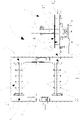
Figure 1 shows, according to a frontal view, an apparatus for foaming doors for refrigerators according to the invention; -
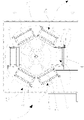
Figure 2 is a top view of the apparatus inFigure 1 ; -
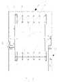
Figure 3 shows a drum unit - of the apparatus according to the invention - housed inside a heating chamber; -
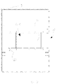
Figure 4 shows a service and transfer carousel that is part of the apparatus according to the invention; -
Figure 5 is a horizontal section of the heating chamber containing the drum unit; -
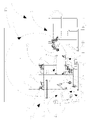
Figure 6 is a top view of the service and transfer carousel and of a foaming station included in the apparatus; -
Figure 7 is a side view of the apparatus in which in the foreground the service and transfer carousel and the foaming station are visible; -
Figure 8 shows an enlarged portion ofFigure 7 ; -
Figure 9 is a view that is similar toFigure 7 but shows the service and transfer carousel and the foaming station in a different operating position; -
Figure 10 is another side view of the containing chamber with the drum unit; -
Figure 11 shows schematically a modular moulding unit that includes the two moulding elements and respective upper and lower reinforcing modular superstructures; -
Figures 12 and 13 show second respectively top and side views of the modular moulding unit ofFigure 11 ; -
Figure 14 shows enlarged details of centring and coupling means provided on the superstructures of the modular moulding unit; -
Figure 15 shows a modular moulding unit (with reinforcing superstructures) in closed configuration; -
Figure 16 is an enlarged detail showing presser rolling means that is provided in the drum unit of the apparatus; -
Figure 17 shows schematically a portion of modular moulding unit - containing a door to be foamed - on which a pressing rolling means acts. - With reference to the attached Figures, an apparatus 1 is shown for foaming substantially two-dimensional objects, i.e. having two dimensions that are much greater than a third dimension.
- The apparatus 1 (and the corresponding foaming method) is particularly suitable for foaming doors or pairs of
doors 2 for refrigerators of domestic or industrial type, or also for foaming door-lids for chest freezers, insulating panels for display benches, doors and windows for houses and buildings and other products. - The
objects 2 to be foamed by the apparatus 1 are provided withouter coating elements 3, 3', such as half-shells or shaped panels made of plastics, metal or slabs or sheets that are flat, curved, or shaped by thermoforming, coupled for shaping a hollow box possibly having a circumferential seal between which foaming occurs to generate an intermediate layer 6 made of thermally insulating phenol or polyurethane material. - In the apparatus 1 according to the invention, a plurality of
modular moulding units 4 is included, each consisting of afirst half mould 5A and of asecond half mould 5B that are mutually couplable/uncouplable, that are suitable for receivingrespective coating elements 3, 3' intended to define the outer surfaces of thecorresponding objects 2 to be obtained. As shown better inFigures 11 to 15 , thefirst half mould 5A and thesecond half mould 5B are fitted removably to respective reinforcingmodular superstructures superstructure half mould support pallet half moulds superstructures - The reinforcing
superstructures coupling elements 51A, 51B (male elements and female elements), suitable for ensuring correct positioning and reciprocal coupling of the reinforcingsuperstructures modular moulding unit 4. - The centring and
coupling elements 51A, 51B are for example of the taper pin (male element) type that engages a respective slot (female element). - According to one possible variant, the
modular moulding units 4 consist only of the twohalf moulds pressing rollers 7, 8. - The apparatus 1 comprises a
rotatable drum unit 9, configured for storing themodular moulding units 4 and advancing along at least part of a closed advancement path P along which polymerization and shape stabilization process occurs for the foamed objects 2. The apparatus comprises a containingchamber 15 provided with a thermostating system inside which thedrum unit 9 is housed. - The containing
chamber 15, in particular, comprises a hot air kiln and is configured for subjecting themodular moulding units 4, advancing along the advancement path P, to a heating step to promote the polymerization process della chemically reactive mixture. - The
rotatable drum unit 9 is rotatable around a horizontal rotation axis A2 and is configured for receiving themodular moulding units 4 with the greater dimensions thereof oriented longitudinally parallel to said rotation axis A2. - Owing to this configuration, the overall dimensions are minimized, or, with the same overall dimensions, storage of a greater number of
modular moulding units 4 on thedrum unit 9 is permitted. - On the
drum unit 9, a series is fitted of first rolling means 7 that are further than the rotation axis A2, and a series of second rolling means 8 placed at a shorter distance from the rotation axis A2 than the first rolling means 7. - The first 7 and second 8 rolling means are arranged for inserting, positioning and maintaining
modular moulding units 4 in a clamped condition on thedrum unit 9. - As will be clearer from the following description, the first 7 and second 8 rolling means ensure stable closure and clamping of the half moulds 5A, 5B that are in reciprocal contact without having to use bolts, padlocks or similar devices to keep the single
modular moulding units 4 closed. - The action of clamping and maintaining in a closed position the
modular moulding units 4 is achieved by applying opposing pressure actions that are exerted by the aforesaid first 7 and second 8 rolling means that come into contact on opposite sides on eachmodular moulding unit 4. - The presence of the mutually couplable superstructures or reinforcing
structures respective half moulds modular moulding unit 4. - The first rolling means 7 and the second rolling means 8 comprise respectively first pressing
rollers 7 and second pressing rollers 8 arranged at a reciprocal operating distance D so as to define, on therotatable drum unit 9, a plurality of housing cells C1, ..., Cn or housing cubicles intended for receiving the same number of respectivemodular moulding units 4. Inserting and extracting amodular moulding unit 4 into and from a housing cell C1, ..., Cn is possible through atransit opening 30 obtained in the containingchamber 15. In particular, thetransit opening 30 is obtained at a height corresponding to the lowest position that each housing C1, ..., Cn can adopt in the rotation of thedrum unit 9. - The first
pressing rollers 7 and the second pressing rollers 8 are mutually spaced apart and arranged to exert on the opposite faces of eachmodular moulding unit 4 opposite pressure and clamping actions to contrast from the exterior the thrusts exerted by the expanding foam inside themodular moulding unit 4. - The
modular moulding units 4 can be adapted to the gap (size in section) of the housing cell C, i.e. to the operating distance D between the firstpressing rollers 7 and the second pressing rollers 8, owing to theaforementioned support pallets pallets structures pressing rollers 7 and the second pressing rollers 8 are idling rollers, i.e. fitted in a freely rotatable manner to thedrum unit 9. - In accordance with a second embodiment, the first
pressing rollers 7 and the second pressing rollers 8 are motor-driven rollers that are drivable to perform respectively the insertion and expulsion of eachmodular moulding unit 4 into/from the corresponding housing cell C1, ..., Cn obtained on thedrum unit 9. - In this case, all the first
pressing rollers 7 of a series and all the second pressing rollers 8 of a second series 8 are driven by a single shared motion-transmission element 19 that can comprise a belt, a chain, or other equivalent mechanical transmission means. - In accordance with a third embodiment, the first rolling means 7 and the second rolling means 8 comprise rollers configured with a convex profile to adapt to deflecting actions. In accordance with a fourth embodiment, the first rolling means 7 and the second rolling means 8 comprise rollers configured with a coating made of an elastic material such as rubber to exert a better distributed action on said
drum unit 9. - In accordance with a fifth embodiment, the first rolling means 7 and the second rolling means 8 comprise rollers configured with circumferential slots distributed to exert concentrated actions in strengthened parts of the mould.
- The
transmission element 19 is wound alternatingly along a path of the "zig-zag" first on a roller of one series and subsequently on a corresponding conjugated roller of the other series of pressing rollers and is moved by arespective motor 20, for example an electric motor. - Owing to this configuration, a drive system is defined for the rollers that is at the same time significantly simplified and equally effective.
- The motor-driven
pressing rollers 7, 8, in addition to performing the function of positioning and maintaining themodular moulding units 4 in a well-closed position, also perform the function of promoting the insertion and expulsion of themoulding units 4 into/from thedrum unit 9 simply, fast and precisely. - The apparatus 1 further comprises a service and transfer
carousel 10 placed in a position adjacent to thedrum unit 9 and rotatable around a vertical axis A1. - As will be clear from the following description, at the service and transfer carousel 10 a service zone-station I (entering/exiting the drum unit 9) and a service zone-station II are defined, for the preparing and loading operations.
- Precisely, the service and transfer
carousel 10 comprises asupport plane 23 divided into twoparts modular moulding units 4 placed on sides opposite the vertical axis A1: precisely, amodular moulding unit 4 that has to be subjected, in a service zone Zs, to preparing and loading operations, and amodular moulding unit 4 that is already ready for foaming (in open mould or in closed mould configuration) are supported simultaneously, themodular moulding unit 4 that is already ready for foaming is intended, once closed, to be loaded onto thedrum unit 9 in the appropriate housing shell Cn. - Each
part reduction gear 29, around a horizontal axis so as to vary the lying plane thereof. In this manner, it is possible to tilt a half mould in the service zone Zs, thus facilitating and making more ergonomic the operations for a possible operator. - The
support plane 23 is rotated around the vertical axis A1 owing to the presence oftoothed coupling 27 connected to adrive motor 28. - The service and transfer
carousel 10 is thus configured for enabling - in the aforesaid service zone Zs - operations of preparing, loading with subsequent closing and insertion of themodular moulding units 4 on thedrum unit 9. - Further, the service and transfer
carousel 10 is configured for the operations of removing themodular moulding units 4 from thedrum unit 9 and for the subsequent operations of opening and removing the foamedobjects 2 from themodular moulding units 4. - The service and transfer
carousel 10 is rotatable by 180°, in opposite rotation directions and in an alternating manner, around the vertical axis A1 to transfer amodular moulding unit 4 that has just been prepared from the aforesaid service zone Zs to a proximity position for insertion into thedrum unit 9 and for transferring a modular moulding unit 4 - containing the foamedobject 2 and removed from the drum unit 9 - again to the service zone Zs to enable theobject 2 that has just been obtained to be removed and to make new preparing and loading operations possible. - In one embodiment, the operations of removing
finished objects 2 and the operations of preparing and loading moulding units are performed manually, by an operator O operating near the service zone Zs. - In another embodiment, the apparatus comprises a handling device configured for removing, in an automated manner, the
finished objects 2 and for loading and positioning in the open half moulds 5A, 5Bnew coating elements 3, 3' or shells and/or inserts to be foamed. On the service and transfercarousel 10, two takingmembers 13A, 13B of the suction or gripper or equivalent type are provided that are configured for coupling/uncoupling thefirst half mould 5A from therespective half mould 5B to open and close eachmodular moulding unit 4. - The two taking
members 13 are arranged so as to be able to each operate on arespective parte 23A andpart 23B of thesupport plane 23. - Precisely, the service and transfer
carousel 10 comprises astationary crosspiece 21 placed at a certain height and supported by avertical upright 25, to which twomotors 22 are fitted to move therespective taking members 13A and 13B. - Each taking
member 13 is supported by arack 24 that engages a toothed wheel mechanism driven by arespective motor 22, or reduction gear, so as to be able to move vertically. In this manner, the takingmember 13 can be raised or lowered to uncouple/couple a half mould from/with the other half mould. - The
parts support plane 23 that is included in the service and transfercarousel 10 comprisesupport rollers 16 for themodular moulding units 4 and which enable amodular moulding unit 4 to slide when it has to be loaded onto thedrum unit 9. - The
rollers 16 of thesupport plane 23, in one embodiment, are idling rollers. In this case, a pushing and pullingdevice 12 is provided that is configured for inserting removing amodular moulding unit 4 into/from, the respective housing cell C1, ..., Cn of thedrum unit 9. The pushing and pullingdevice 12, that can be for example of the pneumatic or hydraulic cylinder type or be electrically driven, acts to push/pull amodular moulding unit 4, sliding themodular moulding unit 4 on theroller plane 16 indicated above that is obtained on the service and transfercarousel 10. - Between the service and transfer
carousel 10 and thedrum unit 9, afurther roller plane 17 can be interposed to facilitate the sliding transit and transfer of themodular moulding units 4 from theservice carousel 10 to thedrum unit 9 and vice versa. - The
further roller plane 17 is also used to enable a suitable spacing to be set between the service and transfercarousel 10 and thedrum unit 9, for example in order to facilitate possible maintenance tasks or for other needs. - In another embodiment, the
rollers 16 of thesupport plane 23 are motor-driven and are driven by amotor 26. - The
rollers 16 can intervene to translate themodular moulding unit 4 with respect to thedrum unit 9, to replace or assist the aforesaid pushing and pullingdevice 12. - In the apparatus 1, a foaming station Fs is included that is located outside the
drum unit 9 and in a position adjacent to the service and transfercarousel 10. - The foaming station Fs includes one or more mixing heads 11 configured for dispensing the chemically reactive mixture in "open mould" mode on an open
modular moulding unit 4 or operating in "closed mould" mode, i.e. to inject the mixture inside the closedmodular moulding units 4. - In the latter case, in the closed
modular moulding units 4, suitable injection holes are obtained through which the mixing heads 11 can inject the mixture into themodular moulding units 4. - The mixing head/s 11 can be moved by suitable actuators of hydraulic or electric type etc. to be moved by sliding on suitable guides to near the
modular moulding unit 4 before dispensing the reactive mixture. - In another embodiment (not shown), the foaming station is placed on the
drum unit 9 and has one or more mixing heads positioned to operate directly on themodular moulding units 4 inserted on thedrum unit 9. - In this case, the mixing head/s 11 are configured for injecting the chemically reactive mixture - in "closed mould' mode - through the suitable injection holes made in the closed
modular moulding units 4 containing the objects to be foamed. - The apparatus 1 is provided with a mould-changing station W (schematized in
Figure 2 ) arranged for enabling one or moremodular moulding units 4 to be replaced or only afirst half mould 5A and or asecond half mould 5B with others of different size/geometry without the need to interrupt the advancement and process of the remainingmodular moulding units 4. - The mould-changing station W, in particular, comprises a roller plane suitable for receiving a
modular moulding unit 4 on which it is desired to make the change size. - The mould-changing station W, by way of non-limiting example, is placed in the vicinity of the service and transfer
carousel 10, for example near the zone-station II. Nevertheless, it is possible to choose to arrange the mould-changing station in other desired zones. For example, a mould-changing station W' can be provided that is placed on an opposite side of thedrum unit 9 with respect to the service and transfercarousel 10 alternatively to or in combination with the mould-changing station W that has just been mentioned. - In this manner, in the containing
chamber 15, another suitable transit opening (similar but opposite the transit opening 30) can be obtained to enable themodular moulding units 4 to transit between the mould-changing station W' anddrum unit 9. - The mould-changing station W' can also act as a station for initializing the foaming process, i.e. for the initial and transitory loading operations of all the
modular moulding units 4 on thedrum unit 9. - Owing to the presence of the mould-changing station (W and/or W'), in combination with the particularity of having
modular moulding units 4 that are completely distinct and separable from the drum unit 9 (i.e. devoid of parts that are permanently connected to the drum unit 9) replacing moulds is made very convenient, easy and versatile to respond to geometry/size change needs for theobjects 2, such as inparticular doors 2, to be foamed. - In this manner, it is thus possible to manage flexibly and in an optimized manner the increasingly great number of geometric door shapes that are different from one another on the same production line, obtaining high productivity of the apparatus 1 with a maximum reduction of undesired downtime, to permit the required door model change during the sequential production of doors.
- The apparatus 1 comprises a control unit CU configured for rotating in an indexed manner the
drum unit 9 and for synchronizing the sequential operations of removing themodular moulding units 4 from thedrum unit 9, opening and removing the foamedobject 2 and loadingrespective coating elements 3, 3' and possible inserts intended for the subsequent foaming and conveying step, along the advancement path P on thedrum unit 9. - To sum up, it is pointed out that in the case of open mould foaming, the operation of mixing the
modular moulding unit 4 must occur, together with the operation of closing themoulding unit 4 itself, before the transfer of the latter to thedrum unit 9. The other operations can be performed by choice in the zone-station I or in the zone-station II on the basis of evaluation criteria of lesser operating time and/or according to specific needs/neces sities/preferences. - Generally speaking, a possible operating sequence that is actuatable with the apparatus 1 involves, with reference to the zone-station I and to the zone-station II, the following operations:
- ZONE-STATION I:
- a1 - entry of already processed closed
modular moulding unit 4 coming fromdrum unit 9 - b1 - rotation of the
carousel 10 - c1 - foaming on
modular moulding unit 4 that has just been prepared - d1 - closure of the
modular moulding unit 4 - e1 - insertion of the
modular moulding unit 4 onto thedrum unit 9 - f1 - rotation of the
drum unit 9.
- a1 - entry of already processed closed
- ZONE-STATION II:
- a2 - opening of the
modular moulding unit 4 - b2 - automatic or manual extraction of doors
- c2 - inspection with possible cleaning of the mould
- d2 - automatic or manual loading of doors
- g2 - rotation of the service and transfer
carousel 10.
- a2 - opening of the
- The operation of the apparatus 1 is disclosed concisely below.
- Once the transitional process initialization step has terminated, with the loading of the
modular moulding units 4 onto the drum unit 9 (for example using the station W') and once a full running condition has been reached, the following procedure is used. Following an indexed rotation of thedrum unit 9, from a first housing cell C1, a firstmodular moulding unit 4 is extracted that is transferred to the service and transfercarousel 10, in a closed condition, on the positionedpart 23 near the foaming zone Fs, i.e. in the zone-station I (for example on thepart 23B of thecarousel 10, as visible inFigures 2 and7 ). - Immediately afterwards, the service and transfer
carousel 10 rotates to bring and open the aforesaid firstmodular moulding unit 4 in the service zone Zs. Thecarousel 10 can open themodular moulding unit 4 during rotation, so that the latter reaches the service zone Zs that is already in open configuration. - Simultaneously, the aforesaid rotation takes a previous
modular moulding unit 4 that is already loaded from the zone-station II to the zone-station I, at the foaming station Fs where it can be closed preventively (in the case of "closed mould' foaming), or can first receive the mixture (foamed in "open mould") and is subsequently reclosed and transferred immediately to the housing cell C1 of the drum that remained empty. - The
drum unit 9 then rotates by one step and takes a secondmodular moulding unit 4 to the extraction position where it is transferred from a housing cell C2 topart 23 B (zone-station I) of thecarousel 10 and the cycle is repeated. - In the service zone Zs, an operator O (or the possible robotized device) extracts - from said first open
modular moulding unit 4 placed on the carousel 10 - the foameddoor 2, after which he positions thenew coating elements 3, 3' to be sent to a subsequent foaming cycle. - On the half moulds, specific housings and magnets are provided to maintain in a correct position the
coating elements 3, 3' or shells. - Upon termination of the preparing and loading operations, the
carousel 10 rotates by 180 degrees to move said firstmodular moulding unit 4 to the foaming zone Fs. - The rotation thus takes the first modular moulding unit 4 - supported by the
part 23 A - to the zone-station I near the foaming station Fs and the second modular moulding unit 4 - supported by thepart 23 B - opposite the service zone Zs (zone-station II). - In the zone-station I, the foaming station Fs intervenes to dispense the mixture. The mixture is dispensed in "open mould" or also in "closed mould" mode - after the half moulds 5A, 5B have been reciprocally closed preliminarily by the corresponding taking
member 13. - Once introduction of the reactive mixture has terminated, the first
modular moulding unit 4, housed on thepart 23 A, is immediately closed if open, and pushed to penetrate - through the transit opening 30 - into the facing housing cell C2 of thedrum unit 9. - The transfer of a closed
modular moulding unit 4 occurs by the pushing and pullingdevice 12 and/or by driving the motor-drivenrollers 16 of thesupport plane 13 included in thetransfer carousel 10 and subsequently by also driving thepressing rollers 7 and 8 placed on thedrum unit 9. - At the end of insertion of the
modular moulding unit 4 into the corresponding housing cell C, thedrum unit 9 is rotated by a step, so as to position the subsequent housing cell containing another now processedmoulding unit 4, at thetransit opening 30 to be extracted - by driving thepressing rollers 7, 8 and/or the intervention of the pulling and pushing device 12 - and positioned on thetransfer carousel 10. - At this point, the
carousel 10 can rotate by 180 degrees in a reverse direction to take saidmodular moulding unit 4 that has just been removed to the service station Zs to perform thereupon new preparing and loading operations, whilst simultaneously anothermoulding unit 4 that is already prepared and supplied with the mixture and is waiting on thecarousel 10 can be re-inserted into the free housing cell (Cn). - The aforesaid steps are repeated sequentially and in a synchronized manner also owing to the help of the control unit CU that controls the rotation by angular steps of the
drum unit 9, the rotation by 180°, in alternating directions, of the service and transfercarousel 10, and driving the other components of the apparatus 1. - All the aforesaid operations are performed in a comparatively short time compared with prior-art systems.
- It is pointed out that the
modular moulding units 4 are opened and closed far from the zone-station II. This means, in the case of the presence of an operator O assigned to extraction, preparation and loading operations, that any danger of injury being caused to the operator is eliminated. Safety levels in the workplace near the apparatus 1 are thus raised. Owing to the configuration that has just been disclosed, many operations (for example the preparation of amodular moulding unit 4, foaming anothermodular moulding unit 4 and subsequent insertion thereof into the drum unit 9) occur at least partially simultaneously, thus in masked time, which leads to a significant reduction in cycle time compared with known foaming systems. - As can be seen from what has been disclosed, the apparatus 1 and the corresponding method enable the objects disclosed above to be reached. In particular, great versatility of use and productivity of the apparatus 1 are achieved, which permits refrigerator door foaming time to be reduced.
- The apparatus 1 permits extreme flexibility of use, with the possibility of adapting in real time to variable geometric shapes of the half moulds of a door, without having to imply undesired prolonged machine downtime.
- The
rotatable drum unit 9, equipped with thepressing rollers 7, 8, is structurally simplified and lighter than known apparatuses that are weighed down by complex mould-holder press devices. - The significant structural and functional simplification of the apparatus 1 also translates into greater mechanical reliability and reduced overall dimensions. As the inertia mass is reduced, the apparatus 1 can also operate at higher speeds than prior-art apparatuses.
- Owing to the complete separability of the
modular moulding units 4 from thedrum unit 9, replacement of one or moremodular moulding units 4 or only afirst half mould 5A and or of asecond half mould 5B with others of a different size/geometry without the need to interrupt the advancement and process of the remainingmodular moulding units 4 is easy and immediate. - The apparatus 1 thus successfully meets current needs of the refrigerator manufacturing or similar industries, in which the range of models on offer with many different sizes and geometric configurations is increasing constantly.
- The apparatus 1 according to the invention is thus able to cater for the sequence of requests coming from the market, making the implementation of a foaming method of the "just in time" type possible.
- Consequently, owing to the flexibility and optimation made possible by the apparatus 1 and method according to the invention, there are advantages also from the point of view of the reduction or even elimination of accumulated stocks of single models in the warehouse. It is possible to configure and size the apparatus 1 in a desired manner according to the dimensions/types of the objects to be processed and variations on and/or additions to what has been disclosed above and illustrated in the attached drawings is possible.
Claims (27)
- Method for foaming objects (2) with two dimensions that prevail over a third dimension and are provided with outer coating elements (3, 3') between which an intermediate layer (6) of expanded polyurethane or phenol material is interposed, comprising the steps of:i). providing a plurality of modular moulding units (4) each consisting of a pair of modular reinforcing and coupling structures (50A and 50B) configured for receiving, or in which there are obtained, respectively a first half mould (5A) and a second half mould (5B) that are mutually couplable/uncouplable, that are suitable for receiving respective coating elements (3, 3') for coating said objects (2) to be foamed and intended to be conveyed along a closed advancement path (P) along which a polymerization and shape stabilization process occurs for the foamed objects (2);ii). arranging a rotatable drum unit (9) for storing said plurality of modular moulding units (4) to be advanced along said closed advancement path (P), said rotatable drum unit (9) being configured with first rolling means (7) and second rolling means (8) for inserting, positioning and maintaining in a clamped condition said modular moulding units (4),iii). setting said first rolling means (7) and second rolling means (8) at a reciprocal operating distance (D) so as to define, on said rotatable drum unit (9), a plurality of housing cells (C1, C2, ..., Cn) for respective modular moulding units (4),iv). arranging, in an outer service zone (Zs) and on a service and transfer carousel (10) placed adjacent to said rotatable drum unit (9), a first modular moulding unit (4) in open configuration, and positioning on the respective first half mould (5A) and second half mould (5B) of said first modular moulding unit (4) respective outer coating elements (3, 3'),v). completing on said first modular moulding unit (4), in said service zone (Zs), the preliminary preparation and loading operations for a subsequent foaming step that involves introducing into said first modular moulding unit (4), by one or more mixing heads (11), a certain quantity of chemically reactive mixture to obtain the respective foamed object (2),vi). transferring said first modular moulding unit (4), in closed configuration, from said service zone (Zs) to said rotatable drum unit (9), by inserting said first modular moulding unit (4) into a respective free housing cell (C1) so as tovii). subject said first modular moulding unit (4) to opposing pressure and clamping actions that are exerted by the respective first rolling means (7) and second rolling means (8) acting on opposite faces of said first modular moulding unit (4), and contrasting from the exterior on said first modular moulding unit (4) the thrusts exerted by the expanding foam by a contrasting action exerted by said first rolling means (7) and second rolling means (8),viii). rotating by an angular step said rotatable drum unit (9) to advance said modular moulding unit (4) along said closed advancement path (P) andix). removing from a second housing cell (C2) a second modular moulding unit (4) that has now reached completion of said closed advancement path (P) along which the polymerization process of said chemically reactive mixture and the shape stabilization of the foamed object (2) enclosed therein occurred, andx). transferring, by said service and transfer carousel (10), said second modular moulding unit (4) to said service zone (Zs) to permit the operations of opening and removing the foamed object (2) and starting new preparing and loading operations further outer coating elements (3, 3') for foaming a further object (2) whereas a third modular moulding unit (4) that has completed the closed advancement path (P) is moved from said rotatable drum unit (9) to said service and transfer carousel (10), said method being CHARACTERIZED IN THAT each closed modular moulding unit (4) is inserted into and removed from, the respective housing cell (C1,..Cn) of the drum unit (9) by a pushing and pulling device (12) configured for sliding the modular moulding unit (4) on a roller plane provided on said service and transfer carousel (10), and wherein said first rolling means (7) and said second rolling means (8) comprise idler pressing rollers that are supported in a freely rotatable manner on said drum unit (9).
- Method according to claim 1, wherein said drum unit (9) is rotated in an indexed manner and for each modular moulding unit (4), the steps are repeated sequentially of removing the modular moulding unit (4) from said drum unit (9), opening and removing the foamed object (2) and loading respective coating elements (3, 3') to be sent to a subsequent foaming and conveying step, by said drum unit (9), along said advancement path (P).
- Method according to claim 1 or 2, wherein a feeding step is provided in which said reactive mixture is fed to each modular moulding unit (4) in open configuration, so as to perform mixture dispensing in "open mould" mode by one or more mixing heads (11), said feeding step being performed on said service and transfer carousel (10) after loading and positioning the respective coating elements (3, 3') and before closing said modular moulding unit (4) and consequent introduction thereof into a housing cell (C1,..Cn) of said rotatable drum unit (9), in which said feeding step, performed in "open mould" condition, pours said quantity of chemically reactive mixture onto one of said first half mould (5A) and second half mould (5B) and, at the end of pouring of said quantity, said first half mould (5A) and second half mould (5B) are coupled reciprocally so as to close the corresponding modular moulding unit (4), after which said closed modular moulding unit (4) is immediately inserted into said drum unit (9).
- Method according to claim 1 or 2, wherein there is a feeding step for feeding said mixture into each modular moulding unit (4) in closed configuration, so as to perform mixture dispensing in "closed mould" mode by one or more mixing heads (11) that are inserted into suitable injection holes obtained in the modular moulding unit (4), said feeding step being performed on said service and transfer carousel (10) after closure of said modular moulding unit (4) following the loading of the respective coating elements (3, 3'), and before said modular moulding unit (4) is inserted into a housing cell (C1,..Cn) of said rotatable drum unit (9).
- Method according to claim 1 or 2, wherein, after each closed modular moulding unit (4) - containing coating elements (3, 3') - has been inserted into the respective housing cell (C1, ..., Cn), on said drum unit (9), a feeding step is provided for feeding said mixture in "closed mould" mode into said modular moulding unit (4) by one or more mixing heads (11) that are inserted into suitable injection holes made in said modular moulding unit (4).
- Method according to any one of the preceding claims, wherein, once a foamed object (2) is removed from the respective open modular moulding unit (4) and, at the end of the preparing and loading operations new coating elements (3, 3'), said service and transfer carousel (10) is rotated by 180°, in a first rotation direction, around a vertical axis (A1) to prepare the modular moulding unit (4) that has just been loaded for the subsequent mixture feeding steps and subsequent insertion thereof into said drum unit (9), and wherein, once a moulding unit (4) that contains a foamed object (2) has been removed from the drum unit (9) and positioned on said service and transfer carousel (10), said service and transfer carousel (10) is rotated by 180°, in a second rotation direction opposite said first direction, to take said modular moulding unit (4) to the service zone (Zs) where the object (2) can be removed that has just been obtained to permit new preparing and loading operations.
- according to any one of the preceding claims, wherein said first rolling means (7) and/or said second rolling means (8) comprise motor-driven pressing rollers and wherein said motor-driven rollers are driven to perform respectively the insertion and expulsion of each modular moulding unit (4) into/from the corresponding housing cell (C1, ..., Cn) of said drum unit (9).
- Method according to any one of the preceding claims, wherein said rotatable drum unit (9) rotates around a horizontal rotation axis (A2) and said modular moulding units (4) are loaded onto said rotatable drum unit (9) with the larger dimensions thereof oriented longitudinally parallel to said rotation axis (A2), so as to minimize the overall dimensions and/or enable, with the same overall dimensions, storage of a greater number of modular moulding units (4) on said drum unit (9).
- Method according to any one of the preceding claims, wherein the first half mould (5A) is uncoupled from the respective half mould (5B) to open the modular moulding unit (4) by taking members (13) of the suction or gripper or equivalent type, and wherein removing finished objects (2) and loading coating elements (3, 3') or shells and/or inserts is performed in an automated manner by a handling device or manually by an operator.
- Method according to any one of the preceding claims, wherein said drum unit (9) is housed inside a containing chamber (15) provided with a thermostating system, and wherein the modular moulding units (4) that advance along said advancement path (P) are subjected to a heating step to promote the polymerization process.
- Method according to any one of the preceding claims, wherein the first half mould (5A) and second half mould (5B) of a modular moulding unit 4 are fitted removably to respective reinforcing modular superstructures (50A, 50B) and in which, between each reinforcing superstructure (50A, 50B) and the respective half mould (10A, 10B) a support pallet (14A, 14B) is interposable that permits rapid and easy replacement of the half moulds (5A, 5B) without also having to extract the reinforcing superstructures (50A, 50B).
- Method according to any one of the preceding claims, wherein, near said service zone (ZS) or other zone adjacent to said drum unit (9), one or more modular moulding units (4) or only said first half mould (5A) or said second half mould (5B) are replaced with others of different size/geometry, without having to stop the advancement and process of the remaining modular moulding units (4).
- Method according to any one of the preceding claims, wherein said is a polyurethane or phenol mixture and wherein said objects (2) comprise: doors of refrigerators and of refrigerator apparatuses with shell-shaped coating elements (3, 3'), cushions or parts of seats of motor vehicles, walls for a display bench, parts of insulating walls or coatings for a building, panels and other products having two dimensions that prevail over a third dimension devoid of or provided with outer coating elements made of plastics, metal or slabs or sheets that are flat, curved, corrugated or shaped in a desired manner.
- Method according to any one of the preceding claims, wherein said first rolling means (7) and said second rolling means (8) are so configured as to define rollers having a convex profile to adapt to deflecting actions, or rollers having a coating made of an elastic material such as rubber to exert a better distributed action on said drum unit (9), or so as to define rollers configured with circumferential slots to exert concentrated actions in strengthened parts of the mould.
- Apparatus for foaming objects (2) with two dimensions that prevail over a third dimension and are provided with outer coating elements (3, 3') between which an intermediate layer (6) of expanded polyurethane or phenol material is interposed, comprising:- a plurality of modular moulding units (4) each consisting of a pair of modular reinforcing and coupling structures (50A and 50B) configured for receiving, or in which there are obtained, respectively a first half mould (5A) and a second half mould (5B) that are mutually couplable/uncouplable, that are suitable for receiving respective coating elements (3, 3') for coating said objects (2) to be foamed and intended to be conveyed along a closed advancement path (P) along which a polymerization and shape stabilization process occurs for the foamed objects (2);- an indexed rotatable drum unit (9) configured for storing said plurality of modular moulding units (4) to be advanced along said closed advancement path (P),- to said rotatable drum unit (9) the first rolling means (7) and second rolling means (8) being fitted for inserting, positioning and maintaining in a clamped condition said modular moulding units (4),- said first rolling means (7) and second rolling means (8) being arranged at a reciprocal operating distance (D) so as to define, on said rotatable drum unit (9), a plurality of housing cells (C1, ..., Cn) for respective modular moulding units (4),- said first rolling means (7) and second rolling means (8) being mutually spaced and arranged to exert on the opposite faces of each modular moulding unit (4) opposing pressure and clamping actions to contrast from the exterior the thrusts exerted by the expanding foam inside the modular moulding unit (4),- a service and transfer carousel (10) adjacent to said drum unit (9), configured for the operations of preparing, loading, foaming in "open mould' or in "closed mould" mode, closing and insertion of the modular moulding units (4) on said drum unit (9), for the operations of removing the modular moulding units (4) from said drum unit (9) and for the subsequent operations of opening and removing the coated objects (2) from the modular moulding units (4), said apparatus (2) being CHARACTERIZED IN THAT it comprises a pushing and pulling device (12) to insert each modular moulding unit (4) into and remove each modular moulding unit (4) from a respective housing cell (C1,..Cn) of the drum unit (9), said pushing and pulling device (12) being configured for sliding the modular moulding unit (4) on support rollers (16) provided on said service and transfer carousel (10), and in which said first rolling means (7) and said second rolling means (8) comprise idling rollers supported in a freely rotatable manner on said drum unit (9), between said service and transfer carousel (10) and said drum unit (9) a further roller plane (17) being interposable for the sliding transit of the modular moulding units (4) between said service and transfer carousel (10) and said drum unit (9).
- Apparatus according to claim 15, comprising a foaming station (Fs) placed outside said drum unit (9) and adjacent to said service and transfer carousel (10), said foaming station (Fs) including one or more mixing heads (11) configured for dispensing chemically reactive mixture in "open mould" mode to an open modular moulding unit (4), or for introducing mixture in "closed mould" mode into a closed modular moulding unit (4) through suitable injection holes made in the latter.
- Apparatus according to claim 15, comprising a foaming station placed on said drum unit (9) and having one or more mixing heads positioned to operate directly on the modular moulding units (4) placed on said drum unit (9), said one or more mixing heads (11) being configured for inserting chemically reactive mixture - in "closed mould" mode - through suitable injection holes made in the closed modular moulding unit (4).
- Apparatus according to any one of claims 15 to 17, wherein said service and transfer carousel (10) is rotatable by 180°, in opposite rotation directions, around a vertical axis (A1) for transferring in sequence a modular moulding unit (4) that has just been prepared from an outer service zone (Zs) to a proximity position (Fs) for foaming and inserting into said drum unit (9), and for transferring a modular moulding unit (4) - containing a foamed object (2) and removed from the drum unit (9) - from the removal zone to the service zone (Zs) to enable the object (2) to be removed that has just been obtained to permit new preparing and loading operations, in which said carousel (10) comprises a support plane (23) defined by two parts (23A, 23B) arranged on opposite sides and mirrored with respect to said vertical axis (A1) and each suitable for hooking, supporting and transferring a respective modular moulding unit (4).
- Apparatus according to any one of claims 15 to 18, wherein said first rolling means (7) and/or said second rolling means (8) comprise motor-driven rollers that are drivable to perform respectively the insertion and expulsion of each modular moulding unit (4) into/from the corresponding housing cell (C1,...Cn..) of said drum unit (9), in which all the rollers of a first series of pressing rollers (7) and all the rollers of a second series of pressing rollers (8) are drivable by a single shared motion-transmission element (19) of the belt or chain type, that is wound according to a path of the "zig-zag" type alternately first on a roller of a series and subsequently on a corresponding conjugated roller of the other series of pressing rollers, said motion-transmission element (19) being moved by a motor (20).
- Apparatus according to any one of claims 15 to 19, wherein said rotatable drum unit (9) is rotatable around a horizontal rotation axis (A2) and is configured for receiving said modular moulding units (4) with the greater dimensions thereof oriented longitudinally parallel to said rotation axis (A2), so as to minimize the overall dimensions and/or enable, with the same overall dimensions, storage of a greater number of modular moulding units (4) on said drum unit (9).
- Apparatus according to any one of claims 15 to 20, further comprising taking members (13) of the suction or gripper or equivalent type configured for coupling/uncoupling the first half mould (5A) with/from the respective half mould (5B) to open/close the modular moulding units (4).
- Apparatus according to any one of claims 15 to 21, further comprising a handling device for removing the finished objects (2) and loading and positioning coating elements (3, 3') or shells and/or inserts.
- Apparatus according to any one of claims 15 to 22, comprising a containing chamber (15) provided with a thermostating system inside which said drum unit (9) is housed, said containing chamber (15) being configured for subjecting said modular moulding units (4), advancing along said advancement path (P), to a heating step to promote the polymerization process.
- Apparatus according to any one of claims 15 to 23, wherein the first half mould (5A) and the second half mould (5B) of each modular moulding unit (4) are fitted removably on respective reinforcing superstructures (50A, 50B) and wherein, between each reinforcing superstructure (50A, 50B) and the respective half mould (10A, 10B) a support pallet (14A, 14B) is interposable that permits rapid and easy replacement of the half moulds (5A, 5B) without also having to extract the reinforcing superstructures (50A, 50B), and in which said reinforcing superstructures (50A, 50B) include centring and coupling elements 51A, 51B, suitable for ensuring correct positioning and reciprocal coupling of the reinforcing superstructures 50A, 50B in the closed configuration of the modular moulding unit (4).
- Apparatus according to any one of claims 15 to 24, further comprising a mould-changing station (W; W') that is suitable for enabling one or more modular moulding units (4) or only a first half mould (5A) and/or a second half mould (5B) to be replaced with others of different size/geometry, without having to stop the advancement and process of the remaining modular moulding units (4).
- Apparatus according to any one of claims 15 to 25, further comprising a control unit (CU) configured for rotating in an indexed manner said drum unit (9) and synchronizing the sequential operations of removing the modular moulding units (4) from said drum unit (9), opening and removing the foamed object (2), loading respective coating elements (3, 3') and possible inserts, for the subsequent foaming and conveying step, along said advancement path (P).
- Apparatus according to any one of claims 15 to 26, wherein said first rolling means (7) and said second rolling means (8) comprise rollers configured with a convex profile to adapt to deflecting actions, or comprise rollers configured with a coating made of an elastic material such as rubber to exert a better distributed action on said drum unit (9), or comprise rollers configured with circumferential slots distributed to exert concentrated actions on strengthened parts of the mould.
Applications Claiming Priority (1)
| Application Number | Priority Date | Filing Date | Title |
|---|---|---|---|
| IT102020000027522A IT202000027522A1 (en) | 2020-11-17 | 2020-11-17 | FOAMING METHOD AND APPARATUS |
Publications (3)
| Publication Number | Publication Date |
|---|---|
| EP4000848A1 true EP4000848A1 (en) | 2022-05-25 |
| EP4000848B1 EP4000848B1 (en) | 2024-01-31 |
| EP4000848C0 EP4000848C0 (en) | 2024-01-31 |
Family
ID=74557041
Family Applications (1)
| Application Number | Title | Priority Date | Filing Date |
|---|---|---|---|
| EP21208302.6A Active EP4000848B1 (en) | 2020-11-17 | 2021-11-15 | Foaming method and apparatus |
Country Status (2)
| Country | Link |
|---|---|
| EP (1) | EP4000848B1 (en) |
| IT (1) | IT202000027522A1 (en) |
Citations (4)
| Publication number | Priority date | Publication date | Assignee | Title |
|---|---|---|---|---|
| WO2013054255A1 (en) * | 2011-10-10 | 2013-04-18 | Cannon Ergos S.P.A. | Method and apparatus for vacuum moulding of polyurethane material |
| WO2015032908A1 (en) | 2013-09-06 | 2015-03-12 | Cannon S.P.A. | Method and apparatus for simultaneously foaming two or more objects |
| EP3037237A1 (en) * | 2014-12-19 | 2016-06-29 | Cannon S.p.A. | Method and apparatus for foaming objects |
| EP3112115A1 (en) * | 2015-06-26 | 2017-01-04 | Cannon S.p.A. | Method and apparatus for conveying and foaming objects |
-
2020
- 2020-11-17 IT IT102020000027522A patent/IT202000027522A1/en unknown
-
2021
- 2021-11-15 EP EP21208302.6A patent/EP4000848B1/en active Active
Patent Citations (4)
| Publication number | Priority date | Publication date | Assignee | Title |
|---|---|---|---|---|
| WO2013054255A1 (en) * | 2011-10-10 | 2013-04-18 | Cannon Ergos S.P.A. | Method and apparatus for vacuum moulding of polyurethane material |
| WO2015032908A1 (en) | 2013-09-06 | 2015-03-12 | Cannon S.P.A. | Method and apparatus for simultaneously foaming two or more objects |
| EP3037237A1 (en) * | 2014-12-19 | 2016-06-29 | Cannon S.p.A. | Method and apparatus for foaming objects |
| EP3112115A1 (en) * | 2015-06-26 | 2017-01-04 | Cannon S.p.A. | Method and apparatus for conveying and foaming objects |
Also Published As
| Publication number | Publication date |
|---|---|
| IT202000027522A1 (en) | 2022-05-17 |
| EP4000848B1 (en) | 2024-01-31 |
| EP4000848C0 (en) | 2024-01-31 |
Similar Documents
| Publication | Publication Date | Title |
|---|---|---|
| EP3112115B1 (en) | Method and apparatus for conveying and foaming objects | |
| EP3037237B1 (en) | Method and apparatus for foaming objects | |
| US5591463A (en) | Apparatus for the thermoforming and stacking of hollow objects incorporating a base formed from thermoplastics sheet material | |
| WO2015032908A1 (en) | Method and apparatus for simultaneously foaming two or more objects | |
| CN108859069A (en) | A kind of ton of bucket is blow molded self-test automatic assembly line | |
| JPH0686084B2 (en) | Molding equipment for molded products | |
| WO2013054255A1 (en) | Method and apparatus for vacuum moulding of polyurethane material | |
| UA46704C2 (en) | METHOD OF MANUFACTURE OF HOLLOW ITEMS, ESPECIALLY OF PLASTIC PROCUREMENTS, AND DEVICES FOR ITS IMPLEMENTATION | |
| EP4000848B1 (en) | Foaming method and apparatus | |
| WO2004091881A2 (en) | Continuous twin sheet thermoforming process and apparatus | |
| CN113213106A (en) | Shaft sleeve sealing and feeding mechanism | |
| JPS6127168B2 (en) | ||
| US4519766A (en) | Apparatus for manufacturing three-dimensional work pieces | |
| EP2586589B1 (en) | Thermoforming press and thermoforming process using said press | |
| CN112872214A (en) | Special automatic forming machine for lifting ring | |
| US11745398B2 (en) | Multiple-jig foaming apparatus and relative foaming method | |
| CN211192830U (en) | Textile machinery pulley assembling machine | |
| CN113878797B (en) | Automatic manufacturing equipment for insert type injection molding production | |
| CN218022426U (en) | Automatic production line for heat-sealing and packaging products | |
| CN117183387A (en) | Production line and production method of acoustic bag | |
| CN212241834U (en) | Mold opening and closing device, mold and foamed product production line | |
| EP0796167B1 (en) | Method and apparatus for loading labels into a mould of a thermoforming machine | |
| CN121845287A (en) | Shaping system | |
| IT202000008818A1 (en) | METHOD AND APPARATUS FOR FOAMING SUBSTANTIALLY TWO-DIMENSIONAL OBJECTS | |
| CN121845286A (en) | Preheating pressing method |
Legal Events
| Date | Code | Title | Description |
|---|---|---|---|
| PUAI | Public reference made under article 153(3) epc to a published international application that has entered the european phase |
Free format text: ORIGINAL CODE: 0009012 |
|
| STAA | Information on the status of an ep patent application or granted ep patent |
Free format text: STATUS: THE APPLICATION HAS BEEN PUBLISHED |
|
| AK | Designated contracting states |
Kind code of ref document: A1 Designated state(s): AL AT BE BG CH CY CZ DE DK EE ES FI FR GB GR HR HU IE IS IT LI LT LU LV MC MK MT NL NO PL PT RO RS SE SI SK SM TR |
|
| STAA | Information on the status of an ep patent application or granted ep patent |
Free format text: STATUS: REQUEST FOR EXAMINATION WAS MADE |
|
| 17P | Request for examination filed |
Effective date: 20220729 |
|
| RBV | Designated contracting states (corrected) |
Designated state(s): AL AT BE BG CH CY CZ DE DK EE ES FI FR GB GR HR HU IE IS IT LI LT LU LV MC MK MT NL NO PL PT RO RS SE SI SK SM TR |
|
| GRAP | Despatch of communication of intention to grant a patent |
Free format text: ORIGINAL CODE: EPIDOSNIGR1 |
|
| STAA | Information on the status of an ep patent application or granted ep patent |
Free format text: STATUS: GRANT OF PATENT IS INTENDED |
|
| INTG | Intention to grant announced |
Effective date: 20230104 |
|
| GRAJ | Information related to disapproval of communication of intention to grant by the applicant or resumption of examination proceedings by the epo deleted |
Free format text: ORIGINAL CODE: EPIDOSDIGR1 |
|
| STAA | Information on the status of an ep patent application or granted ep patent |
Free format text: STATUS: REQUEST FOR EXAMINATION WAS MADE |
|
| INTC | Intention to grant announced (deleted) | ||
| GRAP | Despatch of communication of intention to grant a patent |
Free format text: ORIGINAL CODE: EPIDOSNIGR1 |
|
| STAA | Information on the status of an ep patent application or granted ep patent |
Free format text: STATUS: GRANT OF PATENT IS INTENDED |
|
| INTG | Intention to grant announced |
Effective date: 20230824 |
|
| GRAS | Grant fee paid |
Free format text: ORIGINAL CODE: EPIDOSNIGR3 |
|
| GRAA | (expected) grant |
Free format text: ORIGINAL CODE: 0009210 |
|
| STAA | Information on the status of an ep patent application or granted ep patent |
Free format text: STATUS: THE PATENT HAS BEEN GRANTED |
|
| AK | Designated contracting states |
Kind code of ref document: B1 Designated state(s): AL AT BE BG CH CY CZ DE DK EE ES FI FR GB GR HR HU IE IS IT LI LT LU LV MC MK MT NL NO PL PT RO RS SE SI SK SM TR |
|
| REG | Reference to a national code |
Ref country code: GB Ref legal event code: FG4D Ref country code: CH Ref legal event code: EP |
|
| REG | Reference to a national code |
Ref country code: DE Ref legal event code: R096 Ref document number: 602021008941 Country of ref document: DE |
|
| REG | Reference to a national code |
Ref country code: IE Ref legal event code: FG4D |
|
| U01 | Request for unitary effect filed |
Effective date: 20240222 |
|
| U07 | Unitary effect registered |
Designated state(s): AT BE BG DE DK EE FI FR IT LT LU LV MT NL PT SE SI Effective date: 20240301 |
|
| REG | Reference to a national code |
Ref country code: LT Ref legal event code: MG9D |
|
| PG25 | Lapsed in a contracting state [announced via postgrant information from national office to epo] |
Ref country code: IS Free format text: LAPSE BECAUSE OF FAILURE TO SUBMIT A TRANSLATION OF THE DESCRIPTION OR TO PAY THE FEE WITHIN THE PRESCRIBED TIME-LIMIT Effective date: 20240531 |
|
| PG25 | Lapsed in a contracting state [announced via postgrant information from national office to epo] |
Ref country code: GR Free format text: LAPSE BECAUSE OF FAILURE TO SUBMIT A TRANSLATION OF THE DESCRIPTION OR TO PAY THE FEE WITHIN THE PRESCRIBED TIME-LIMIT Effective date: 20240501 |
|
| PG25 | Lapsed in a contracting state [announced via postgrant information from national office to epo] |
Ref country code: HR Free format text: LAPSE BECAUSE OF FAILURE TO SUBMIT A TRANSLATION OF THE DESCRIPTION OR TO PAY THE FEE WITHIN THE PRESCRIBED TIME-LIMIT Effective date: 20240131 Ref country code: RS Free format text: LAPSE BECAUSE OF FAILURE TO SUBMIT A TRANSLATION OF THE DESCRIPTION OR TO PAY THE FEE WITHIN THE PRESCRIBED TIME-LIMIT Effective date: 20240430 |
|
| PG25 | Lapsed in a contracting state [announced via postgrant information from national office to epo] |
Ref country code: ES Free format text: LAPSE BECAUSE OF FAILURE TO SUBMIT A TRANSLATION OF THE DESCRIPTION OR TO PAY THE FEE WITHIN THE PRESCRIBED TIME-LIMIT Effective date: 20240131 |
|
| PG25 | Lapsed in a contracting state [announced via postgrant information from national office to epo] |
Ref country code: RS Free format text: LAPSE BECAUSE OF FAILURE TO SUBMIT A TRANSLATION OF THE DESCRIPTION OR TO PAY THE FEE WITHIN THE PRESCRIBED TIME-LIMIT Effective date: 20240430 Ref country code: NO Free format text: LAPSE BECAUSE OF FAILURE TO SUBMIT A TRANSLATION OF THE DESCRIPTION OR TO PAY THE FEE WITHIN THE PRESCRIBED TIME-LIMIT Effective date: 20240430 Ref country code: IS Free format text: LAPSE BECAUSE OF FAILURE TO SUBMIT A TRANSLATION OF THE DESCRIPTION OR TO PAY THE FEE WITHIN THE PRESCRIBED TIME-LIMIT Effective date: 20240531 Ref country code: HR Free format text: LAPSE BECAUSE OF FAILURE TO SUBMIT A TRANSLATION OF THE DESCRIPTION OR TO PAY THE FEE WITHIN THE PRESCRIBED TIME-LIMIT Effective date: 20240131 Ref country code: GR Free format text: LAPSE BECAUSE OF FAILURE TO SUBMIT A TRANSLATION OF THE DESCRIPTION OR TO PAY THE FEE WITHIN THE PRESCRIBED TIME-LIMIT Effective date: 20240501 Ref country code: ES Free format text: LAPSE BECAUSE OF FAILURE TO SUBMIT A TRANSLATION OF THE DESCRIPTION OR TO PAY THE FEE WITHIN THE PRESCRIBED TIME-LIMIT Effective date: 20240131 |
|
| PG25 | Lapsed in a contracting state [announced via postgrant information from national office to epo] |
Ref country code: PL Free format text: LAPSE BECAUSE OF FAILURE TO SUBMIT A TRANSLATION OF THE DESCRIPTION OR TO PAY THE FEE WITHIN THE PRESCRIBED TIME-LIMIT Effective date: 20240131 |
|
| PG25 | Lapsed in a contracting state [announced via postgrant information from national office to epo] |
Ref country code: PL Free format text: LAPSE BECAUSE OF FAILURE TO SUBMIT A TRANSLATION OF THE DESCRIPTION OR TO PAY THE FEE WITHIN THE PRESCRIBED TIME-LIMIT Effective date: 20240131 |
|
| PG25 | Lapsed in a contracting state [announced via postgrant information from national office to epo] |
Ref country code: SM Free format text: LAPSE BECAUSE OF FAILURE TO SUBMIT A TRANSLATION OF THE DESCRIPTION OR TO PAY THE FEE WITHIN THE PRESCRIBED TIME-LIMIT Effective date: 20240131 |
|
| PG25 | Lapsed in a contracting state [announced via postgrant information from national office to epo] |
Ref country code: CZ Free format text: LAPSE BECAUSE OF FAILURE TO SUBMIT A TRANSLATION OF THE DESCRIPTION OR TO PAY THE FEE WITHIN THE PRESCRIBED TIME-LIMIT Effective date: 20240131 |
|
| PG25 | Lapsed in a contracting state [announced via postgrant information from national office to epo] |
Ref country code: SK Free format text: LAPSE BECAUSE OF FAILURE TO SUBMIT A TRANSLATION OF THE DESCRIPTION OR TO PAY THE FEE WITHIN THE PRESCRIBED TIME-LIMIT Effective date: 20240131 |
|
| PG25 | Lapsed in a contracting state [announced via postgrant information from national office to epo] |
Ref country code: SM Free format text: LAPSE BECAUSE OF FAILURE TO SUBMIT A TRANSLATION OF THE DESCRIPTION OR TO PAY THE FEE WITHIN THE PRESCRIBED TIME-LIMIT Effective date: 20240131 Ref country code: SK Free format text: LAPSE BECAUSE OF FAILURE TO SUBMIT A TRANSLATION OF THE DESCRIPTION OR TO PAY THE FEE WITHIN THE PRESCRIBED TIME-LIMIT Effective date: 20240131 Ref country code: RO Free format text: LAPSE BECAUSE OF FAILURE TO SUBMIT A TRANSLATION OF THE DESCRIPTION OR TO PAY THE FEE WITHIN THE PRESCRIBED TIME-LIMIT Effective date: 20240131 Ref country code: CZ Free format text: LAPSE BECAUSE OF FAILURE TO SUBMIT A TRANSLATION OF THE DESCRIPTION OR TO PAY THE FEE WITHIN THE PRESCRIBED TIME-LIMIT Effective date: 20240131 |
|
| REG | Reference to a national code |
Ref country code: DE Ref legal event code: R097 Ref document number: 602021008941 Country of ref document: DE |
|
| PLBE | No opposition filed within time limit |
Free format text: ORIGINAL CODE: 0009261 |
|
| STAA | Information on the status of an ep patent application or granted ep patent |
Free format text: STATUS: NO OPPOSITION FILED WITHIN TIME LIMIT |
|
| 26N | No opposition filed |
Effective date: 20241101 |
|
| U20 | Renewal fee for the european patent with unitary effect paid |
Year of fee payment: 4 Effective date: 20241130 |
|
| REG | Reference to a national code |
Ref country code: CH Ref legal event code: PL |
|
| PG25 | Lapsed in a contracting state [announced via postgrant information from national office to epo] |
Ref country code: MC Free format text: LAPSE BECAUSE OF FAILURE TO SUBMIT A TRANSLATION OF THE DESCRIPTION OR TO PAY THE FEE WITHIN THE PRESCRIBED TIME-LIMIT Effective date: 20240131 |
|
| REG | Reference to a national code |
Ref country code: CH Ref legal event code: PL |
|
| PG25 | Lapsed in a contracting state [announced via postgrant information from national office to epo] |
Ref country code: CH Free format text: LAPSE BECAUSE OF NON-PAYMENT OF DUE FEES Effective date: 20241130 |
|
| PG25 | Lapsed in a contracting state [announced via postgrant information from national office to epo] |
Ref country code: IE Free format text: LAPSE BECAUSE OF NON-PAYMENT OF DUE FEES Effective date: 20241115 |
|
| PG25 | Lapsed in a contracting state [announced via postgrant information from national office to epo] |
Ref country code: HU Free format text: LAPSE BECAUSE OF FAILURE TO SUBMIT A TRANSLATION OF THE DESCRIPTION OR TO PAY THE FEE WITHIN THE PRESCRIBED TIME-LIMIT; INVALID AB INITIO Effective date: 20211115 |
|
| PG25 | Lapsed in a contracting state [announced via postgrant information from national office to epo] |
Ref country code: CY Free format text: LAPSE BECAUSE OF FAILURE TO SUBMIT A TRANSLATION OF THE DESCRIPTION OR TO PAY THE FEE WITHIN THE PRESCRIBED TIME-LIMIT; INVALID AB INITIO Effective date: 20211115 |