EP4000831A1 - Working unit for scraping panels and scraping method - Google Patents
Working unit for scraping panels and scraping method Download PDFInfo
- Publication number
- EP4000831A1 EP4000831A1 EP21206841.5A EP21206841A EP4000831A1 EP 4000831 A1 EP4000831 A1 EP 4000831A1 EP 21206841 A EP21206841 A EP 21206841A EP 4000831 A1 EP4000831 A1 EP 4000831A1
- Authority
- EP
- European Patent Office
- Prior art keywords
- scraping
- panel
- advancing direction
- working unit
- edge
- Prior art date
- Legal status (The legal status is an assumption and is not a legal conclusion. Google has not performed a legal analysis and makes no representation as to the accuracy of the status listed.)
- Pending
Links
Images


Classifications
-
- B—PERFORMING OPERATIONS; TRANSPORTING
- B27—WORKING OR PRESERVING WOOD OR SIMILAR MATERIAL; NAILING OR STAPLING MACHINES IN GENERAL
- B27D—WORKING VENEER OR PLYWOOD
- B27D5/00—Other working of veneer or plywood specially adapted to veneer or plywood
- B27D5/006—Trimming, chamfering or bevelling edgings, e.g. lists
Definitions
- the present invention relates to a scraping unit for scraping plastic edges applied on the sides of the panels and related method and scraping method.
- the invention relates to a so-called pass-through edge banding machine, equipped with a scraping unit, designed and manufactured in particular to allow the vertical/horizontal sides of a wood or chipboard panel band-edged with plastic edges to be worked, but which can be used for the processing of any type of panel, in which it is necessary to carry out scraping different edges.
- edgebanding machines for edgebanding wooden or similar panels by means of a band, generally made of plastic (PVC, ABS or Polypropylene).
- a plastic edgebanding tape is generally applied to panels made of wood, such as chipboard, to allow for a better finish.
- This edge banding tape generally comes in standard sizes to fit panels of different thicknesses. Therefore, after an edge banding tape is applied to the edges of a panel, excesses are created with respect to the surface of the same, so that further machining has to be carried out, in order to remove these excesses and refine the panel to allow its use.
- the edge banding tape is typically applied to the side edges of the panel, as well as to the front and the rear edges of the panel (i.e., on the 4 sides of the panel).
- edge banding machines allow the machining of the moving panels, to allow a high machining speed. For this reason, such machines are also known as pass-through edge banding machines.
- edge banding machines in general must carry out machining on all four sides of the panel. Therefore, it is necessary to carry out both a so-called trimming working and an end-trimming working.
- these machines In order to carry out the aforementioned processes, these machines generally provide a so-called chamfering group, a rounding unit or profiler gr., and a so-called edge scraper group.
- the chamfering group comprises two opposing rotating cutters arranged, in such a way as to eliminate the excess of the edging tape from the edges of the panel, generally on the long sides of the panel as it moves along an advancing direction.
- the aforementioned edge scraper group is used, which provides two blades also opposite each other, kept in contact with the edge to be machined by means of suitable springs, while the panel passes in the aforementioned advancing direction.
- a technical problem of the edge banding machines according to the priori art is that of not allowing machining of the vertical edges of the panel, which obviously are smaller than the transversal longitudinal dimension of the panel itself, as well as of the relative cusps that these vertical edges, form with the side and front or rear edges of the panel.
- edge banding machines according to the prior art do not allow the scraping of the front and rear vertical edges and of the relative cusps formed by them with the longitudinal edges when the panel is moving.
- the object of the present invention to propose an edge banding machine that is capable of overcoming the limits of those of the prior art, and in particular of allowing a precise machining also of the vertical edges of the panels while the panel is moving.
- a working unit of a panel wherein said panel is movable in an advancing direction having one face facing said working unit, comprising a fixed frame, with respect to which said panel is movable in said advancing direction, and at least one scraping group, installed on said fixed frame, comprising a scraping device, provided with a scraping tool, for carrying out the scraping of edges of said panel, characterized in that said scraping group is movable with respect to said fixed frame perpendicular with respect to the advancing direction of said panel and parallel to a vertical edge of said face facing said working unit, so as to arrange said scraping tool for working at least one vertical edge and at least one cusp by means of said scraping tool.
- said at least one scraping group may comprise a supporting frame at least one guide arranged parallel to said advancing direction of said panel, wherein said supporting frame is horizontally movable with respect to said advancing direction, and said scraping device may be fixed to said supporting frame.
- said at least one scraping group may comprise a supporting frame, at least one guide arranged perpendicular with respect to said advancing direction of said panel, wherein said supporting frame is perpendicularly and vertically movable with respect to said advancing direction, and said scraping device may be fixed to said supporting frame.
- said at least one scraping group may be configured for carrying out the scraping of the cusps of said panel, and said scraping device may be rotatable with respect to said panel while it moves along said advancing direction, so as to arrange said scraping tool for working at least one longitudinal edge of said face of the panel facing said working unit.
- said scraping device comprises a supporting plate, coupled to said supporting frame, so as to allow the rotation of said scraping device with respect to a direction transverse to said advancing direction.
- said working unit may comprise a rotating device, associated to said supporting plate, that allows the rotation of said scraping device around the axis perpendicular to the advancing direction of the panel and perpendicular to the surface of the panel.
- said scraping device may comprise a surface copier and a front copier associated with said supporting plate, for positioning said scraping device so as to work said at least one vertical edge, said at least one cusp and said at least one longitudinal edge.
- said surface copier may comprise a wheel, intended to slide on the upper and lower surfaces, and on the side surfaces of the panel.
- said working unit may comprise an upper scraping group, wherein said scraping device is configured to move and rotate for working, the front vertical edge, the upper longitudinal edge, the rear vertical edge, the upper front cusp, and the upper rear cusp of said panel, and a lower scraping group, arranged in series to said upper scraping group, wherein the respective scraping device is configured to move and rotate for working, the front vertical edge, the lower longitudinal edge, the rear vertical edge, the lower front cusp, and the lower rear cusp.
- an edge banding plant comprising moving members, for allowing the movement of at least one panel in an advancing direction, at least one edge banding station, for coupling an edge banding tape to a panel that moves in an advancing direction above mentioned moving members, a working unit according to any one of the preceding claims, for carrying out the scraping of edges and cusps of said panel.
- a panel P working unit according to the present invention can be seen, which is indicated with the numerical reference 1.
- Said panels P can be made of chipboard, solid wood, fiberglass, plastic and the like.
- the panel P is previously edge banded with an edge banding tape and possibly pre-worked with a chamfering operation.
- the working unit 1 essentially comprises a supporting fixed frame 2 and an upper scraping group 3 and a lower scraping group 4 installed on said fixed frame 2, arranged in series, one downstream of the other, and suitable for to carry out, as will be better described in the following, the scraping of several edges of a panel P, movable along an advancing direction indicated by the arrow A.
- the upper scraping group 3 is downstream of the lower scraping group 4.
- the fixed frame 2 has the function of supporting said upper scraping group 3 and said lower scraping group 4. Said fixed frame 2 is also intended to be in turn installed on the main frame of an edge banding plant (not shown in the figures). In some embodiments, the fixed frame 2 of the working unit 1 can also be part of the main frame of an edge banding plant, which possibly also comprises other machining stations.
- the lower scraping group 4 here taken as a reference for the description, comprises a supporting frame 41, and one or more guides 42, of pneumatic type, vertically arranged (vertical guides 421) and perpendicularly and horizontally (horizontal guides 422) with respect to the advancing direction A of the panel P.
- the supporting frame 41 is movable along the Z direction, while thanks to the guides 422 the support frame is movable along the X direction, which is parallel to the advancing direction A of the panel P, again with reference to the aforementioned Cartesian triad with respect to the fixed frame 2 of the working unit 2.
- the movements in the X and Z directions are performed with controlled actuation, in an interpolation logic with the advancing speed of the panel P.
- Said lower scraping group 4 also comprises a scraping device 43, comprising a supporting plate 431, coupled to the supporting frame 41.
- a rotation device 432 such as an electric motor, which allows the rotation of the entire scraping device 43 and therefore of the copying/tool system 434, 435, 436 around the Y-axis.
- the scraping device 43 is capable of moving vertically along the Z-axis, while horizontally the horizontal guides 422 allow the movement along the X-axis and rotate around the Y-axis.
- the scraping device 43 can be seen in greater detail, even independently of the lower scraping group 4, to which it belongs.
- the scraping device 33 of the upper scraping group 3 is completely similar to the scraping device 43 of the lower scraping group 4.
- the scraping device 43 also comprises a surface copying device 433, provided in turn with a wheel 434, intended for sliding on the upper, lower and lateral surfaces of the panel as will be better described below, a front copier 435, designed to accommodate the panel P to be machined on the stop, and a scraping tool 436, such as a blade or knife, to scraping the edges and the cusps of the panel P to be machined, as better explained below.
- a surface copying device 433 provided in turn with a wheel 434, intended for sliding on the upper, lower and lateral surfaces of the panel as will be better described below
- a front copier 435 designed to accommodate the panel P to be machined on the stop
- a scraping tool 436 such as a blade or knife
- the scraping tool 436 is covered by a protective casing 437, to avoid the escape of any waste during the machining of the panel P. Thanks to the possibility of moving the supporting plate both along the Z-axis by means of the prismatic guides 42, as well as around the Y-axis, it is possible orienting the position of the knife 436, to allow, as will be better explained below, the scraping of different edges and cusps of a panel P.
- the lower scraping group 4 also includes a cable holder 44, for the power supply.
- the upper scraping group 3 is completely similar to the lower scraping group 4, and also in this case it comprises the supporting frame 31, one or more guides 32, the scraping device 33, and the cable holder 34.
- the scraping device 33 in turn comprises the supporting plate 331, the rotation device 332, and the surface copier 333.
- the surface copier 333 comprises the wheel 334, the support plate 335, the blade or knife 336, and the protective carter 337.
- the working unit 1 also comprises a detection device 7, which is generally an optical sensor or any other type, intended to detect the panel P, and in particular the head and tail of the panel P before it is machined, to control the machining programmed on panel P itself.
- a detection device 7 is generally an optical sensor or any other type, intended to detect the panel P, and in particular the head and tail of the panel P before it is machined, to control the machining programmed on panel P itself.
- a generic panel P with a parallelepiped shape and substantially flat, when it reaches the scraping unit 1, faces it showing the face formed by an upper longitudinal edge SIs, a lower longitudinal edge Sli, a front vertical edge Sva, and a rear vertical edge Svp, as shown in figures 7 and 8 .
- edges indicated above form cusps.
- the same figures 7 and 8 show the positions that can be assumed for example by the scraping tool 336 (blade or knife) of the scraping device 33 of the upper scraping group 3.
- the scraping device 33 is arranged so as to scrape the front vertical edge Sva, the upper longitudinal edge SIs, the rear vertical edge Svp, the front upper cusp Cas and the rear upper cusp Cps.
- the scraping tool 436 of the scraping device 43 of the lower scraping group 4 can be arranged so as to scrape, the front vertical edge Sva, the lower longitudinal edge Sli, the rear vertical edge Svp, the lower front cusp Cai and the lower rear cusp Cpi.
- the upper scraping group 3 and the lower scraping group 4 can scrape the entire face of the panel P facing the working unit 1 in a peripheral manner, and not only the upper longitudinal SIs and lower Sli edges, while said panel P moves along the advancing direction A.
- the panel P that reaches the working unit 1 is already edged with the edge banding tape and possibly machined by means of the chamfering unit and/or rounding/profiler unit.
- the wheel 434 of the surface copier 433 can start rolling on the front surface of the panel P, allowing the scraping tool 436 to scrape the front vertical edge Sva and the lower front cusp Csi of the panel P.
- the scraping device 43 is rotated by the rotating device 432 around the Y-axis (again with reference to the Cartesian triad XYZ), so as to allow the scraping tool 436 to scrape the lower side edge Sli, while the panel P is moving in the advancing direction A.
- the scraping device 43 is again rotated by the rotation device 432 about the Y-axis, so as to scrape the lower rear cusp Cpi and the rear vertical edge Svp.
- the three different positions can be observed, indicated by (a), (b), and (c), that the scraping device 43 can assume with respect to the panel P during its passage while it moves in the advancing direction A, rotating thanks to the rotation device 432.
- the scraping device 43 is always in the same position, it rotates only with respect to the Y-axis. It is only the panel P that moves, as mentioned, in the advancing direction A.
- the scraping device 43 is capable of scraping the front vertical edge Sva, the lower front cusp Cai, the lower longitudinal edge Sli, the lower rear cusp (Cpi), and the rear vertical edge Svp, as schematically shown also in figure 10 .
- the scraping device 33 is able to scrape, in order, the front vertical edge Sva, the upper front cusp Cas, the upper longitudinal edge SIs, the rear upper cusp Cps, and the rear vertical edge Svp, as schematically shown also in figure 12 .
- the working unit 1 can also work, or scrape, panels of different shapes.
- an irregularly shaped panel can be observed, which can be easily worked by the scraping device 33, by suitably rotating it by means of the rotation device 332 and the movement Z and Y axes.
- Figure 14 schematically shows an edge banding plant I for panels P, which includes moving members 5, to allow the advancement of the panels P in the advancing direction A, an edge banding station 6, arranged adjacent to the moving members 5.
- the edge banding station 6 is arranged to couple an edge banding tape to a panel P, which advances said movement members along said advancing direction A.
- said edge banding station 6 can optionally provide means for carrying out the edge banding and/or the profiling of the edges of said panel P.
- a working unit 1 as described above is provided, provided with a lower scraping group 4 and an upper scraping group 3, to carry out the scraping of edges and cusps of said panel P.
- FIG. 15 shows a block diagram of the processing method 8 for processing panels P moving in the advancing direction A by means of the working unit 1, comprising the following steps:
- An advantage of the machining unit according to the present invention is that of allowing the scraping of the front and rear vertical edges of a panel as well.
- Another advantage of the machining unit according to the present invention is that of allowing the scraping of all the edges of a panel while it is moving along an advancing direction.
Landscapes
- Life Sciences & Earth Sciences (AREA)
- Engineering & Computer Science (AREA)
- Mechanical Engineering (AREA)
- Wood Science & Technology (AREA)
- Forests & Forestry (AREA)
- Securing Of Glass Panes Or The Like (AREA)
Abstract
Description
- The present invention relates to a scraping unit for scraping plastic edges applied on the sides of the panels and related method and scraping method.
- More specifically, the invention relates to a so-called pass-through edge banding machine, equipped with a scraping unit, designed and manufactured in particular to allow the vertical/horizontal sides of a wood or chipboard panel band-edged with plastic edges to be worked, but which can be used for the processing of any type of panel, in which it is necessary to carry out scraping different edges.
- In the following, the description will be addressed to the machining of a panel edge banded by wood or the like, but it is clear that the same should not be considered limited to this specific use.
- As is well known, there are currently various types of edgebanding machines for edgebanding wooden or similar panels by means of a band, generally made of plastic (PVC, ABS or Polypropylene).
- A plastic edgebanding tape is generally applied to panels made of wood, such as chipboard, to allow for a better finish. This edge banding tape generally comes in standard sizes to fit panels of different thicknesses. Therefore, after an edge banding tape is applied to the edges of a panel, excesses are created with respect to the surface of the same, so that further machining has to be carried out, in order to remove these excesses and refine the panel to allow its use.
- The edge banding tape is typically applied to the side edges of the panel, as well as to the front and the rear edges of the panel (i.e., on the 4 sides of the panel).
- The edge banding machines according to the prior art allow the machining of the moving panels, to allow a high machining speed. For this reason, such machines are also known as pass-through edge banding machines.
- Furthermore, the edge banding machines in general must carry out machining on all four sides of the panel. Therefore, it is necessary to carry out both a so-called trimming working and an end-trimming working.
- In order to carry out the aforementioned processes, these machines generally provide a so-called chamfering group, a rounding unit or profiler gr., and a so-called edge scraper group.
- The chamfering group comprises two opposing rotating cutters arranged, in such a way as to eliminate the excess of the edging tape from the edges of the panel, generally on the long sides of the panel as it moves along an advancing direction.
- It is known, however, that machining by means of the fine trimming group involves imperfections. In fact, the cutters of this unit, given the rotating nature of the parts that perform the machining, can leave "wavy" surfaces and therefore not pleasing to the eye and to the touch. Therefore, for finishing the edges previously machined by the fine trimmer, the aforementioned edge scraper group is used, which provides two blades also opposite each other, kept in contact with the edge to be machined by means of suitable springs, while the panel passes in the aforementioned advancing direction.
- A technical problem of the edge banding machines according to the priori art is that of not allowing machining of the vertical edges of the panel, which obviously are smaller than the transversal longitudinal dimension of the panel itself, as well as of the relative cusps that these vertical edges, form with the side and front or rear edges of the panel.
- This obviously entails considerable limits to the finishing of the panels, which are thus effectively finished only on the longitudinal edge.
- In fact, the edge banding machines according to the prior art do not allow the scraping of the front and rear vertical edges and of the relative cusps formed by them with the longitudinal edges when the panel is moving.
- To carry out the finishing of the vertical edges of the panels carrying out them manually at the end of the edge banding process is currently necessary, with an evident increase in cost and production times.
- It is clear that these procedures are expensive in economic terms.
- In the light of the above, it is, therefore, the object of the present invention to propose an edge banding machine that is capable of overcoming the limits of those of the prior art, and in particular of allowing a precise machining also of the vertical edges of the panels while the panel is moving.
- It is also an object of the present invention to propose a method of working the panels, which allows carrying out the finishing of the vertical edges during the passage of the panels, avoiding that they have to be manually picked up at the end of the working.
- It is, therefore, a specific object of the present invention a working unit of a panel, wherein said panel is movable in an advancing direction having one face facing said working unit, comprising a fixed frame, with respect to which said panel is movable in said advancing direction, and at least one scraping group, installed on said fixed frame, comprising a scraping device, provided with a scraping tool, for carrying out the scraping of edges of said panel, characterized in that said scraping group is movable with respect to said fixed frame perpendicular with respect to the advancing direction of said panel and parallel to a vertical edge of said face facing said working unit, so as to arrange said scraping tool for working at least one vertical edge and at least one cusp by means of said scraping tool.
- Always according to the invention, said at least one scraping group may comprise a supporting frame at least one guide arranged parallel to said advancing direction of said panel, wherein said supporting frame is horizontally movable with respect to said advancing direction, and said scraping device may be fixed to said supporting frame.
- Still according to the invention, said at least one scraping group may comprise a supporting frame, at least one guide arranged perpendicular with respect to said advancing direction of said panel, wherein said supporting frame is perpendicularly and vertically movable with respect to said advancing direction, and said scraping device may be fixed to said supporting frame.
- Advantageously according to the invention, said at least one scraping group may be configured for carrying out the scraping of the cusps of said panel, and said scraping device may be rotatable with respect to said panel while it moves along said advancing direction, so as to arrange said scraping tool for working at least one longitudinal edge of said face of the panel facing said working unit.
- Further according to the invention, said scraping device comprises a supporting plate, coupled to said supporting frame, so as to allow the rotation of said scraping device with respect to a direction transverse to said advancing direction.
- Preferably according to the invention, said working unit may comprise a rotating device, associated to said supporting plate, that allows the rotation of said scraping device around the axis perpendicular to the advancing direction of the panel and perpendicular to the surface of the panel.
- Always according to the invention, said scraping device may comprise a surface copier and a front copier associated with said supporting plate, for positioning said scraping device so as to work said at least one vertical edge, said at least one cusp and said at least one longitudinal edge.
- Still according to the invention, said surface copier may comprise a wheel, intended to slide on the upper and lower surfaces, and on the side surfaces of the panel.
- Advantageously according to the invention, said working unit may comprise an upper scraping group, wherein said scraping device is configured to move and rotate for working, the front vertical edge, the upper longitudinal edge, the rear vertical edge, the upper front cusp, and the upper rear cusp of said panel, and a lower scraping group, arranged in series to said upper scraping group, wherein the respective scraping device is configured to move and rotate for working, the front vertical edge, the lower longitudinal edge, the rear vertical edge, the lower front cusp, and the lower rear cusp.
- It is further object of the present invention an edge banding plant comprising moving members, for allowing the movement of at least one panel in an advancing direction, at least one edge banding station, for coupling an edge banding tape to a panel that moves in an advancing direction above mentioned moving members, a working unit according to any one of the preceding claims, for carrying out the scraping of edges and cusps of said panel.
- It is also object of the present invention a method for working panels moving in an advancing direction by means of a working unit as defined above, comprising the following steps: arranging the scraping tool on a first vertical edge of said panel of the face facing said working unit; moving said scraping tool vertically so as to scrape said first vertical edge of said panel; rotating said scraping tool so as to scrape a cusp of said panel; arranging said scraping members so as to scrape a longitudinal edge of said panel while it moves in said advancing direction; rotating said scraping tool so as to scrape a second cusp of said panel; and moving said scraping tool vertically so as to scrape a second vertical edge of said panel, parallel to said first vertical edge.
- The present invention will be now described, for illustrative but not limitative purposes, according to its preferred embodiments, with particular reference to the figures of the enclosed drawings, wherein:
-
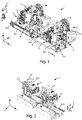
figure 1 shows a front perspective view of a working plant according to the present invention; -
figure 2 shows a rear perspective view of the working plant according tofigure 1 ; -
figure 3 shows a rear view of the working plant according tofigure 1 ; -
figure 4 shows a top view of a scraping device of a scraping group of the processing plant according tofigure 1 , -
figure 5 shows a perspective view of the scraping device according tofigure 4 ; -
figure 6 shows a rear perspective view of the upper scraping device according tofigure 4 ; -
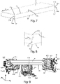
figure 7 shows the different positions of a scraping tool on a panel; -
figure 8 shows a detail offigure 7 ; -
figure 9 shows the different positions of a scraping device of the lower scraping group of the plant according tofigure 1 ; -
figure 10 shows the scraping pattern of the scraping device offigure 9 ; -
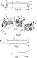
figure 11 shows the different positions of a scraping device of the upper scraping group of the plant according tofigure 1 ; -
figure 12 shows the scraping pattern of the scraping device offigure 11 ; -
figure 13 shows an irregularly shaped panel that can be worked by means of the scraping device of the upper scraping group of the plant according tofigure 1 ; -
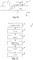
figure 14 shows an edging plant scheme including a working plant according tofigure 1 ; and -
figure 15 shows a flow diagram of the scraping method of a scraping device of the working plant according tofigure 1 . - In the various figures similar parts will be indicated with the same reference numbers.
- With reference to
figures 1 and 2 , a panel P working unit according to the present invention can be seen, which is indicated with the numerical reference 1. Said panels P can be made of chipboard, solid wood, fiberglass, plastic and the like. The panel P is previously edge banded with an edge banding tape and possibly pre-worked with a chamfering operation. - The working unit 1 essentially comprises a supporting
fixed frame 2 and anupper scraping group 3 and alower scraping group 4 installed on saidfixed frame 2, arranged in series, one downstream of the other, and suitable for to carry out, as will be better described in the following, the scraping of several edges of a panel P, movable along an advancing direction indicated by the arrow A. In particular, theupper scraping group 3 is downstream of thelower scraping group 4. - The
fixed frame 2 has the function of supporting saidupper scraping group 3 and saidlower scraping group 4. Saidfixed frame 2 is also intended to be in turn installed on the main frame of an edge banding plant (not shown in the figures). In some embodiments, the fixedframe 2 of the working unit 1 can also be part of the main frame of an edge banding plant, which possibly also comprises other machining stations. - In the following, one of the two
scraping groups - With reference to
figures 1, 2 , and3 , it can be seen that thelower scraping group 4, here taken as a reference for the description, comprises a supportingframe 41, and one ormore guides 42, of pneumatic type, vertically arranged (vertical guides 421) and perpendicularly and horizontally (horizontal guides 422) with respect to the advancing direction A of the panel P. - More specifically, for greater clarity, it is also possible to refer to the Cartesian axis system XYZ shown in
figure 1 , in which the advancing direction of the panel P is arranged along the X-axis. - Thanks to the
guides 421, the supportingframe 41 is movable along the Z direction, while thanks to theguides 422 the support frame is movable along the X direction, which is parallel to the advancing direction A of the panel P, again with reference to the aforementioned Cartesian triad with respect to the fixedframe 2 of the workingunit 2. The movements in the X and Z directions are performed with controlled actuation, in an interpolation logic with the advancing speed of the panel P. - Said
lower scraping group 4 also comprises ascraping device 43, comprising a supportingplate 431, coupled to the supportingframe 41. On said supportingplate 431 there is arotation device 432, such as an electric motor, which allows the rotation of theentire scraping device 43 and therefore of the copying/tool system - In this way, thanks to the
vertical guides 421 and therotation device 432, thescraping device 43 is capable of moving vertically along the Z-axis, while horizontally thehorizontal guides 422 allow the movement along the X-axis and rotate around the Y-axis. Referring also tofigures 4, 5, and 6 , thescraping device 43 can be seen in greater detail, even independently of thelower scraping group 4, to which it belongs. Thescraping device 33 of theupper scraping group 3 is completely similar to thescraping device 43 of thelower scraping group 4. - The
scraping device 43 also comprises asurface copying device 433, provided in turn with awheel 434, intended for sliding on the upper, lower and lateral surfaces of the panel as will be better described below, afront copier 435, designed to accommodate the panel P to be machined on the stop, and ascraping tool 436, such as a blade or knife, to scraping the edges and the cusps of the panel P to be machined, as better explained below. - The
scraping tool 436 is covered by aprotective casing 437, to avoid the escape of any waste during the machining of the panel P. Thanks to the possibility of moving the supporting plate both along the Z-axis by means of the prismatic guides 42, as well as around the Y-axis, it is possible orienting the position of theknife 436, to allow, as will be better explained below, the scraping of different edges and cusps of a panel P. - The
lower scraping group 4 also includes acable holder 44, for the power supply. - As anticipated, the
upper scraping group 3 is completely similar to thelower scraping group 4, and also in this case it comprises the supportingframe 31, one ormore guides 32, thescraping device 33, and thecable holder 34. Thescraping device 33 in turn comprises the supportingplate 331, therotation device 332, and the surface copier 333. The surface copier 333 comprises thewheel 334, the support plate 335, the blade orknife 336, and theprotective carter 337. - Finally, the working unit 1 also comprises a
detection device 7, which is generally an optical sensor or any other type, intended to detect the panel P, and in particular the head and tail of the panel P before it is machined, to control the machining programmed on panel P itself. - The operation of the working unit 1 described above is as follows.
- A generic panel P, with a parallelepiped shape and substantially flat, when it reaches the scraping unit 1, faces it showing the face formed by an upper longitudinal edge SIs, a lower longitudinal edge Sli, a front vertical edge Sva, and a rear vertical edge Svp, as shown in
figures 7 and 8 . - Furthermore, the edges indicated above form cusps. In particular:
- the upper longitudinal edge SIs and the front vertical edge Sva form the front upper cusp Cas;
- the lower longitudinal edge Sli and the front vertical edge Sva form the front lower cusp Cai;
- the upper longitudinal edge SIs and the rear vertical edge Svp form the rear upper cusp Cps; and
- the lower longitudinal edge Sli and the rear vertical edge Svp form the rear lower cusp Cpi.
- The same
figures 7 and 8 show the positions that can be assumed for example by the scraping tool 336 (blade or knife) of thescraping device 33 of theupper scraping group 3. In particular, as can be seen, thescraping device 33 is arranged so as to scrape the front vertical edge Sva, the upper longitudinal edge SIs, the rear vertical edge Svp, the front upper cusp Cas and the rear upper cusp Cps. - Similarly, the
scraping tool 436 of thescraping device 43 of thelower scraping group 4 can be arranged so as to scrape, the front vertical edge Sva, the lower longitudinal edge Sli, the rear vertical edge Svp, the lower front cusp Cai and the lower rear cusp Cpi. - In this way, the
upper scraping group 3 and thelower scraping group 4 can scrape the entire face of the panel P facing the working unit 1 in a peripheral manner, and not only the upper longitudinal SIs and lower Sli edges, while said panel P moves along the advancing direction A. - When a panel P is transported by means of the moving means, which the possible plant in which the working unit 1 is installed is provided with, it is first machined by the
lower scraping group 4 and subsequently by theupper scraping group 3, as shown in particular infigure 1 . - The panel P that reaches the working unit 1 is already edged with the edge banding tape and possibly machined by means of the chamfering unit and/or rounding/profiler unit.
- When the panel P to be machined reaches the
lower scraping group 4, it abuts against thefront copier 435 and thesurface copier 433 of therelative scraping device 43. - In this way, the
wheel 434 of thesurface copier 433 can start rolling on the front surface of the panel P, allowing thescraping tool 436 to scrape the front vertical edge Sva and the lower front cusp Csi of the panel P. - Thereafter, the
scraping device 43 is rotated by therotating device 432 around the Y-axis (again with reference to the Cartesian triad XYZ), so as to allow thescraping tool 436 to scrape the lower side edge Sli, while the panel P is moving in the advancing direction A. - Finally, once the scraping of the lower lateral edge Sli is completed, the
scraping device 43 is again rotated by therotation device 432 about the Y-axis, so as to scrape the lower rear cusp Cpi and the rear vertical edge Svp. Referring now tofigure 9 , the three different positions can be observed, indicated by (a), (b), and (c), that thescraping device 43 can assume with respect to the panel P during its passage while it moves in the advancing direction A, rotating thanks to therotation device 432. Obviously, in the interpretation offigure 8 , thescraping device 43 is always in the same position, it rotates only with respect to the Y-axis. It is only the panel P that moves, as mentioned, in the advancing direction A. - As can be seen, the
scraping device 43 is capable of scraping the front vertical edge Sva, the lower front cusp Cai, the lower longitudinal edge Sli, the lower rear cusp (Cpi), and the rear vertical edge Svp, as schematically shown also infigure 10 . - In a completely analogous way, in
figure 11 , three different positions are observed, indicated with (d), (e), and (f), that thescraping device 33 of theupper scraping group 3 can assume with respect to the panel P during its passage while moving in the advancing direction A. Obviously, in the interpretation offigure 11 , also in this case, thescraping device 33 is found always in the same position. It rotates only with respect to the Y-axis. It is only the panel P that moves, as mentioned, in the advancing direction A. - As can be seen, the
scraping device 33 is able to scrape, in order, the front vertical edge Sva, the upper front cusp Cas, the upper longitudinal edge SIs, the rear upper cusp Cps, and the rear vertical edge Svp, as schematically shown also infigure 12 . - The working unit 1 can also work, or scrape, panels of different shapes. In particular, referring for example to
figure 13 , an irregularly shaped panel can be observed, which can be easily worked by thescraping device 33, by suitably rotating it by means of therotation device 332 and the movement Z and Y axes. -
Figure 14 schematically shows an edge banding plant I for panels P, which includes movingmembers 5, to allow the advancement of the panels P in the advancing direction A, anedge banding station 6, arranged adjacent to the movingmembers 5. Theedge banding station 6 is arranged to couple an edge banding tape to a panel P, which advances said movement members along said advancing direction A. In addition, saidedge banding station 6 can optionally provide means for carrying out the edge banding and/or the profiling of the edges of said panel P. - Downstream of the
edge banding station 6, a working unit 1 as described above is provided, provided with alower scraping group 4 and anupper scraping group 3, to carry out the scraping of edges and cusps of said panel P. - Naturally, other configurations of plants can be envisaged in which the working unit 1 can be integrated.
-
Figure 15 shows a block diagram of theprocessing method 8 for processing panels P moving in the advancing direction A by means of the working unit 1, comprising the following steps: - arranging 81 the
scraping tool scraping devices detection device 7; - moving 82 said
scraping tool - rotating 83 said
scraping tool - arranging 84 said scraping
members - rotating 85 said
scraping tool - vertically moving 86 said
scraping tool - An advantage of the machining unit according to the present invention is that of allowing the scraping of the front and rear vertical edges of a panel as well.
- Another advantage of the machining unit according to the present invention is that of allowing the scraping of all the edges of a panel while it is moving along an advancing direction.
- The present invention has been described for illustrative but not limitative purposes, according to its preferred embodiments, but it is to be understood that modifications and/or changes can be introduced by those skilled in the art without departing from the relevant scope as defined in the enclosed claims.
Claims (11)
- Working unit (1) of a panel (P), wherein said panel (P) is movable in an advancing direction (A) having one face facing said working unit (1), comprisinga fixed frame (2), with respect to which said panel (P) is movable in said advancing direction (A), andat least one scraping group (3, 4), installed on said fixed frame (2), comprising a scraping device (33, 43), provided with a scraping tool (336, 436), for carrying out the scraping of edges of said panel (P),characterizedin that said scraping group (33, 43) is movable with respect to said fixed frame (2) perpendicular with respect to the advancing direction (A) of said panel (P) and parallel to a vertical edge (Sva, Svp) of said face facing said working unit (1), so as to arrange said scraping tool (336, 436) for working at least one vertical edge (Sva, Svp) and at least one cusp (Cas, Cps, Cai, Cpi) by means of said scraping tool (336, 436).
- Working unit (1) according to the preceding claim, characterizedin that said at least one scraping group (3, 4) comprisesa supporting frame (41)at least one guide (322, 422) arranged parallel to said advancing direction (A) of said panel (P), wherein said supporting frame (41) is horizontally movable with respect to said advancing direction (A), andin that said scraping device (33, 43) is fixed to said supporting frame (31,41).
- Working unit (1) according to any one of the preceding claims, characterizedin that said at least one scraping group (3, 4) comprisesa supporting frame (41),at least one guide (321, 421) arranged perpendicular with respect to said advancing direction (A) of said panel (P), wherein said supporting frame (41) is perpendicularly and vertically movable with respect to said advancing direction (A), andin that said scraping device (33, 43) is fixed to said supporting frame (31,41).
- Working unit (1) according to any one of the preceding claims, characterizedin that said at least one scraping group (3,4) is configured for carrying out the scraping of the cusps of said panel (P), andin that said scraping device (33, 43) is rotatable with respect to said panel (P) while it moves along said advancing direction (A), so as to arrange said scraping tool (336, 436) for working at least one longitudinal edge (SIs, Sli) of said face of the panel (P) facing said working unit (1).
- Working unit (1) according to any one of claims 3 or 4, characterized in that said scraping device (33, 43) comprises a supporting plate (331, 431), coupled to said supporting frame (41), so as to allow the rotation of said scraping device (33, 43) with respect to a direction transverse to said advancing direction (A).
- Working unit (1) according to the preceding claim, characterized in that it comprises a rotating device (332, 432), associated to said supporting plate (331, 431), that allows the rotation of said scraping device (43) around the axis (Y) perpendicular to the advancing direction of the panel (P) and perpendicular to the surface of the panel (P).
- Working unit (1) according to any one of the preceding claims, characterized in that said scraping device (33, 43) comprises a surface copier (333, 433) and a front copier (335, 435) associated with said supporting plate (331, 431), for positioning said scraping device (336, 436) so as to work said at least one vertical edge (Sva, Svp), said at least one cusp (Cas, Cps, Cai, Cpi) and said at least one longitudinal edge (SIs, Sli).
- Working unit (1) according to any one of claims 6 or 7, characterized in that said surface copier comprises a wheel (334, 434), intended to slide on the upper and lower surfaces, and on the side surfaces of the panel (P).
- Working unit (1) according to any one of the preceding claims, characterized in that it comprisesan upper scraping group (3), wherein said scraping device (33) is configured to move and rotate for working, the front vertical edge (Sva), the upper longitudinal edge (SIs), the rear vertical edge (Svp), the upper front cusp (Cas) and the upper rear cusp (Cps) of said panel (P), anda lower scraping group (4), arranged in series to said upper scraping group (3), wherein the respective scraping device (43) is configured to move and rotate for working, the front vertical edge (Sva), the lower longitudinal edge (Sli), the rear vertical edge (Svp), the lower front cusp (Cai) and the lower rear cusp (Cpi).
- Edge banding plant (I) comprisingmoving members (5), for allowing the movement of at least one panel (P) in an advancing direction (A),at least one edge banding station (6), for coupling an edge banding tape to a panel (P) that moves in a advancing direction (A) above mentioned moving members,a working unit according to any one of the preceding claims, for carrying out the scraping of edges and cusps of said panel (P).
- Method (8) for working panels (P) moving in an advancing direction (A) by means of a working unit (1) according to any one of claims 1-9, comprising the following steps:arranging (81) the scraping tool on a first vertical edge (Sva) of said panel (P) of the face facing said working unit (1);moving (82) said scraping tool (336, 436) vertically so as to scrape said first vertical edge (Sva) of said panel (P);rotating (83) said scraping tool (336, 436) so as to scrape a cusp (Cas, Cai) of said panel (P);arranging (84) said scraping members (336, 436) so as to scrape a longitudinal edge (SIs, Sli) of said panel (P) while it moves in said advancing direction (A);rotating (85) said scraping tool (336, 436) so as to scrape a second cusp (Cps, Cpi) of said panel (P); andmoving (86) said scraping tool (336, 436) vertically so as to scrape a second vertical edge (Svp) of said panel (P), parallel to said first vertical edge (Sva).
Applications Claiming Priority (1)
| Application Number | Priority Date | Filing Date | Title |
|---|---|---|---|
| IT102020000027363A IT202000027363A1 (en) | 2020-11-16 | 2020-11-16 | WORKING UNIT FOR SCRAPING PANELS AND SCRAPING METHOD. |
Publications (1)
| Publication Number | Publication Date |
|---|---|
| EP4000831A1 true EP4000831A1 (en) | 2022-05-25 |
Family
ID=74557015
Family Applications (1)
| Application Number | Title | Priority Date | Filing Date |
|---|---|---|---|
| EP21206841.5A Pending EP4000831A1 (en) | 2020-11-16 | 2021-11-08 | Working unit for scraping panels and scraping method |
Country Status (2)
| Country | Link |
|---|---|
| EP (1) | EP4000831A1 (en) |
| IT (1) | IT202000027363A1 (en) |
Cited By (1)
| Publication number | Priority date | Publication date | Assignee | Title |
|---|---|---|---|---|
| WO2024231583A1 (en) * | 2023-05-09 | 2024-11-14 | Construcciones Españolas De Herramientas Industriales, S.A. | Device for trimming panel edges |
Citations (6)
| Publication number | Priority date | Publication date | Assignee | Title |
|---|---|---|---|---|
| DE19644137A1 (en) * | 1996-10-23 | 1998-04-30 | Reich Spezialmaschinen Gmbh | Milling machine with adjusting device |
| ITBO970188A1 (en) * | 1997-03-28 | 1998-09-28 | Scm Group Autec Division Spa | EDGEBANDING GROUP |
| US20040089376A1 (en) * | 2002-11-13 | 2004-05-13 | Martin Rose | Edge-routing unit for a program-controlled feed-through machine |
| EP1834744A2 (en) * | 2006-03-16 | 2007-09-19 | BIESSE S.p.A. | Trimming-scraping unit for finishing components of wood or similar |
| EP2527110A1 (en) * | 2011-05-26 | 2012-11-28 | SCM Group S.p.A. | Operating unit, in particular for edgebanding machines |
| CN111633773A (en) * | 2020-07-06 | 2020-09-08 | 东莞市繁茂木工机械设备有限公司 | A fully automatic servo straight edge banding machine |
-
2020
- 2020-11-16 IT IT102020000027363A patent/IT202000027363A1/en unknown
-
2021
- 2021-11-08 EP EP21206841.5A patent/EP4000831A1/en active Pending
Patent Citations (6)
| Publication number | Priority date | Publication date | Assignee | Title |
|---|---|---|---|---|
| DE19644137A1 (en) * | 1996-10-23 | 1998-04-30 | Reich Spezialmaschinen Gmbh | Milling machine with adjusting device |
| ITBO970188A1 (en) * | 1997-03-28 | 1998-09-28 | Scm Group Autec Division Spa | EDGEBANDING GROUP |
| US20040089376A1 (en) * | 2002-11-13 | 2004-05-13 | Martin Rose | Edge-routing unit for a program-controlled feed-through machine |
| EP1834744A2 (en) * | 2006-03-16 | 2007-09-19 | BIESSE S.p.A. | Trimming-scraping unit for finishing components of wood or similar |
| EP2527110A1 (en) * | 2011-05-26 | 2012-11-28 | SCM Group S.p.A. | Operating unit, in particular for edgebanding machines |
| CN111633773A (en) * | 2020-07-06 | 2020-09-08 | 东莞市繁茂木工机械设备有限公司 | A fully automatic servo straight edge banding machine |
Cited By (1)
| Publication number | Priority date | Publication date | Assignee | Title |
|---|---|---|---|---|
| WO2024231583A1 (en) * | 2023-05-09 | 2024-11-14 | Construcciones Españolas De Herramientas Industriales, S.A. | Device for trimming panel edges |
Also Published As
| Publication number | Publication date |
|---|---|
| IT202000027363A1 (en) | 2022-05-16 |
Similar Documents
| Publication | Publication Date | Title |
|---|---|---|
| US6321431B1 (en) | Process and device for removing oxide skin from metal strips | |
| WO2021218258A1 (en) | Automatic edge banding machine, and control system and method therefor | |
| CN101407031B (en) | Disposal screw thread forming numerically controlled grinder for mini milling cutter for printed circuit board | |
| CA2966681C (en) | Machine for cutting stone material | |
| WO2021218257A1 (en) | Machining method of automatic edge banding machine | |
| EP2145744A1 (en) | Apparatus and method for cutting panels | |
| AU2004230856B2 (en) | Coolant delivery apparatus for machine tool | |
| WO2021218256A1 (en) | Control system for automatic edge banding machine | |
| US5144737A (en) | Apparatus for applying and contouring edge strips for plates | |
| CN105174705A (en) | Glass processing integrated machine | |
| CA2247215A1 (en) | Process and device for removing oxide skin from metal strips | |
| EP2527110B1 (en) | Operating unit, in particular for edgebanding machines | |
| EP2388109A2 (en) | Method for machining composite components | |
| CN212312279U (en) | Full-automatic servo straight edge bonding machine | |
| EP3552786B1 (en) | Machine and method for machining an edge of a workpiece | |
| EP4049787B1 (en) | A machine and a method for processing lateral edges of glass plates, plates of stone material or plates of synthetic material | |
| US5651722A (en) | Machine and method for working butt weld seams on band | |
| EP2121228B1 (en) | Machine tool and method for cutting elongated profiled elements | |
| EP2432614B1 (en) | Machine tool | |
| CN111250768B (en) | Milling cutter for processing special-shaped bottom edge of band saw blade, processing device and processing method | |
| IT202000027363A1 (en) | WORKING UNIT FOR SCRAPING PANELS AND SCRAPING METHOD. | |
| CN206253882U (en) | Complex milling machine tool | |
| CN215327747U (en) | Non-contact cambered surface glass cutting equipment | |
| CN212857917U (en) | Beveling machine | |
| CN206914015U (en) | Full-automatic cutting engraving machine |
Legal Events
| Date | Code | Title | Description |
|---|---|---|---|
| PUAI | Public reference made under article 153(3) epc to a published international application that has entered the european phase |
Free format text: ORIGINAL CODE: 0009012 |
|
| STAA | Information on the status of an ep patent application or granted ep patent |
Free format text: STATUS: THE APPLICATION HAS BEEN PUBLISHED |
|
| AK | Designated contracting states |
Kind code of ref document: A1 Designated state(s): AL AT BE BG CH CY CZ DE DK EE ES FI FR GB GR HR HU IE IS IT LI LT LU LV MC MK MT NL NO PL PT RO RS SE SI SK SM TR |
|
| STAA | Information on the status of an ep patent application or granted ep patent |
Free format text: STATUS: REQUEST FOR EXAMINATION WAS MADE |
|
| 17P | Request for examination filed |
Effective date: 20221121 |
|
| RBV | Designated contracting states (corrected) |
Designated state(s): AL AT BE BG CH CY CZ DE DK EE ES FI FR GB GR HR HU IE IS IT LI LT LU LV MC MK MT NL NO PL PT RO RS SE SI SK SM TR |
|
| P01 | Opt-out of the competence of the unified patent court (upc) registered |
Effective date: 20230518 |
|
| STAA | Information on the status of an ep patent application or granted ep patent |
Free format text: STATUS: EXAMINATION IS IN PROGRESS |
|
| 17Q | First examination report despatched |
Effective date: 20250321 |