EP4000720A1 - Befeuchter - Google Patents
Befeuchter Download PDFInfo
- Publication number
- EP4000720A1 EP4000720A1 EP21207252.4A EP21207252A EP4000720A1 EP 4000720 A1 EP4000720 A1 EP 4000720A1 EP 21207252 A EP21207252 A EP 21207252A EP 4000720 A1 EP4000720 A1 EP 4000720A1
- Authority
- EP
- European Patent Office
- Prior art keywords
- housing
- air
- flow
- humidifier
- sealing
- Prior art date
- Legal status (The legal status is an assumption and is not a legal conclusion. Google has not performed a legal analysis and makes no representation as to the accuracy of the status listed.)
- Granted
Links
Images

Classifications
-
- B—PERFORMING OPERATIONS; TRANSPORTING
- B01—PHYSICAL OR CHEMICAL PROCESSES OR APPARATUS IN GENERAL
- B01D—SEPARATION
- B01D63/00—Apparatus in general for separation processes using semi-permeable membranes
- B01D63/06—Tubular membrane modules
- B01D63/066—Tubular membrane modules with a porous block having membrane coated passages
-
- B—PERFORMING OPERATIONS; TRANSPORTING
- B01—PHYSICAL OR CHEMICAL PROCESSES OR APPARATUS IN GENERAL
- B01D—SEPARATION
- B01D63/00—Apparatus in general for separation processes using semi-permeable membranes
- B01D63/08—Flat membrane modules
- B01D63/082—Flat membrane modules comprising a stack of flat membranes
- B01D63/084—Flat membrane modules comprising a stack of flat membranes at least one flow duct intersecting the membranes
- B01D63/085—Flat membrane modules comprising a stack of flat membranes at least one flow duct intersecting the membranes specially adapted for two fluids in mass exchange flow
-
- B—PERFORMING OPERATIONS; TRANSPORTING
- B01—PHYSICAL OR CHEMICAL PROCESSES OR APPARATUS IN GENERAL
- B01D—SEPARATION
- B01D2313/00—Details relating to membrane modules or apparatus
- B01D2313/04—Specific sealing means
- B01D2313/041—Gaskets or O-rings
-
- B—PERFORMING OPERATIONS; TRANSPORTING
- B01—PHYSICAL OR CHEMICAL PROCESSES OR APPARATUS IN GENERAL
- B01D—SEPARATION
- B01D2313/00—Details relating to membrane modules or apparatus
- B01D2313/20—Specific housing
- B01D2313/201—Closed housing, vessels or containers
-
- B—PERFORMING OPERATIONS; TRANSPORTING
- B01—PHYSICAL OR CHEMICAL PROCESSES OR APPARATUS IN GENERAL
- B01D—SEPARATION
- B01D2315/00—Details relating to the membrane module operation
- B01D2315/22—Membrane contactor
-
- H—ELECTRICITY
- H01—ELECTRIC ELEMENTS
- H01M—PROCESSES OR MEANS, e.g. BATTERIES, FOR THE DIRECT CONVERSION OF CHEMICAL ENERGY INTO ELECTRICAL ENERGY
- H01M8/00—Fuel cells; Manufacture thereof
- H01M8/04—Auxiliary arrangements, e.g. for control of pressure or for circulation of fluids
- H01M8/04082—Arrangements for control of reactant parameters, e.g. pressure or concentration
- H01M8/04089—Arrangements for control of reactant parameters, e.g. pressure or concentration of gaseous reactants
- H01M8/04119—Arrangements for control of reactant parameters, e.g. pressure or concentration of gaseous reactants with simultaneous supply or evacuation of electrolyte; Humidifying or dehumidifying
- H01M8/04126—Humidifying
- H01M8/04149—Humidifying by diffusion, e.g. making use of membranes
-
- Y—GENERAL TAGGING OF NEW TECHNOLOGICAL DEVELOPMENTS; GENERAL TAGGING OF CROSS-SECTIONAL TECHNOLOGIES SPANNING OVER SEVERAL SECTIONS OF THE IPC; TECHNICAL SUBJECTS COVERED BY FORMER USPC CROSS-REFERENCE ART COLLECTIONS [XRACs] AND DIGESTS
- Y02—TECHNOLOGIES OR APPLICATIONS FOR MITIGATION OR ADAPTATION AGAINST CLIMATE CHANGE
- Y02E—REDUCTION OF GREENHOUSE GAS [GHG] EMISSIONS, RELATED TO ENERGY GENERATION, TRANSMISSION OR DISTRIBUTION
- Y02E60/00—Enabling technologies; Technologies with a potential or indirect contribution to GHG emissions mitigation
- Y02E60/30—Hydrogen technology
- Y02E60/50—Fuel cells
Definitions
- the invention relates to a humidifier for a fuel cell system according to the preamble of claim 1.
- a humidifier for a fuel cell system is, for example, from DE 10 2013 020 503 A1 known.
- dry cathode supply air is humidified by moist cathode exhaust air, thereby improving the efficiency of the fuel cell system.
- the humidifier usually has a cuboid membrane block made of several water- or water-vapor-permeable membranes and a housing in which the membrane block is accommodated.
- the cathode supply air and the cathode exhaust air are conducted separately from one another, with the water or water vapor being transferred via the membranes of the membrane block from the moist cathode exhaust air into the dry cathode supply air.
- the supply and discharge of the cathode supply air and the cathode exhaust air to/from the membrane block usually takes place at flow-through surfaces.
- the membrane block Due to the design, the membrane block has four flow-through surfaces, which form the periphery of the membrane block, and two airtight end faces, which close the membrane block at the front.
- Air chambers for supplying and discharging the cathode supply air and the cathode exhaust air are assigned to the respective flow surfaces within the housing, which air chambers are appropriately separated from one another in an airtight manner.
- a one-part or multi-part sealing arrangement is often used, which seals the flow-through surfaces from one another along their connecting edges and from one another at the end faces.
- the sealing arrangement has a complex structure and is expensive to manufacture and assemble.
- the object of the invention is therefore to specify an improved or at least alternative embodiment for a humidifier of the generic type, in which the disadvantages described are overcome.
- a humidifier is provided for a fuel cell system for humidifying a dry cathode supply air with a moist cathode exhaust air.
- the humidifier is in particular a membrane humidifier.
- the humidifier has a housing, a membrane block and a sealing arrangement.
- the membrane block is cuboid and has two hermetically sealed and opposite end faces and four through-flow areas.
- the membrane block is accommodated in the housing in such a way that an air chamber is formed between the respective flow area of the membrane block and an opposite area of the housing for supplying or discharging the cathode exhaust air or the cathode supply air to/from the membrane block.
- the respective air chambers are separated from one another in an airtight manner within the housing by means of the sealing arrangement.
- the sealing arrangement is formed from three or four ring seals that are separate from one another, with the respective ring seal being assigned to one of the flow-through surfaces of the membrane block.
- the respective ring seal runs around the edge of the respective assigned flow-through surface and is arranged in a sealing manner between the respective flow-through surface and the housing.
- the sealing arrangement is formed exclusively from three or four ring seals or from exactly three or exactly four ring seals.
- the sealing arrangement has accordingly no further separate elements for sealing the membrane block to the housing.
- the sealing arrangement is particularly simple.
- the respective ring seals are separate from one another or are physically separated from one another and, at the edge, only run around the assigned flow area or exclusively enclose the assigned flow area.
- the respective ring seal thus lies exclusively on the associated flow-through surface and is of flat or planar design.
- an angling or buckling of the respective ring seal over the connecting edges of the membrane block is avoided.
- the respective ring seals do not bridge the connecting edges of the membrane block.
- such a flat or level ring seal can be manufactured in a simplified and cost-effective manner.
- the sealing arrangement has a simple structure and is therefore easier to manufacture and assemble.
- the housing has an internal support structure.
- the membrane block can advantageously be positioned in the housing in a rotationally and non-displaceably fixed manner by the support structure.
- the respective ring seals are arranged in a sealing manner between the respective flow-through surfaces of the diaphragm block and the support structure of the housing.
- the support structure can have sealing surfaces on which the respective ring seals are arranged in a sealing manner.
- the support structure can also have additional ribs or additional surfaces for supporting the membrane block on the flow-through surfaces and/or on the end faces.
- the additional ribs or additional surfaces can contribute to avoiding vibrations of the membrane block during operation of the humidifier. It goes without saying that the support structure and the membrane block are arranged on one another so that they are protected against abrasion.
- the support structure can be formed by a cuboid, partially open inner cage and the membrane block can be accommodated in the inner cage.
- the respective ring seals can be arranged in a sealing manner between the respective flow-through surfaces of the membrane block and the inner cage.
- the ring seal has a sealing frame and a sealing lip protruding from the sealing frame.
- the sealing frame is bonded to the associated through-flow surface, facing away from the sealing lip.
- the sealing frame is preferably glued or welded to the associated flow-through surface.
- the sealing lip is then arranged facing the housing and is in sealing contact with the housing.
- the sealing lip can be inclined inwards or towards the middle of the respective ring seal.
- the respective ring seal can run around the respective assigned flow area of the membrane block spaced inward at the edge, so that the respective connection edges assigned to the respective flow area are exposed and the respective ring seal does not go over the respective connection edges. In other words, angling or buckling of the respective ring seal over the connecting edges of the membrane block is reliably avoided.
- the respective ring seal can be materially connected, preferably glued or welded, to the respective assigned flow area.
- the housing to have a housing body which is open at the longitudinal end and two housing bases.
- the respective through-flow surfaces of the membrane block face the housing body and the end faces of the membrane block face the bottom of the housing.
- the respective housing base closes the housing body at the longitudinal end and is firmly connected to the housing body in an airtight manner.
- One housing base is preferably formed integrally or in one piece with the housing body.
- the other housing base is preferably glued or welded or screwed to the housing body.
- a total of four air chambers are formed between the flow-through surfaces of the membrane block and the opposite areas of the housing and a total of two front air chambers are formed between the end faces of the membrane block and the opposite areas of the housing.
- the sealing arrangement is formed from exactly three ring seals, which are separate or physically separate from one another. Three of the four air chambers are separated from each other and from the fourth air chamber and from the front air chambers by the three ring seals in an airtight manner.
- the fourth air chamber is connected to the two forehead air chambers in an air-conducting manner and thus equalizes the pressure.
- the number of ring seals is minimized, so that the sealing arrangement is particularly simple and the sealing of the humidifier is particularly simplified.
- a total of four air chambers are provided between the through-flow surfaces of the membrane block and the opposite areas of the housing and between the end faces of the membrane block and the opposite areas of the housing a total of two front air chambers are formed.
- the sealing arrangement is formed from exactly four ring seals, which are separate or physically separated from one another.
- the four air chambers are airtightly separated from each other by the four ring seals.
- three of the four air chambers are airtightly separated from the two front air chambers by the ring seals.
- the fourth air chamber is connected to the two forehead air chambers in an air-conducting manner and thus equalizes the pressure.
- a pressure-equalizing connection between the fourth air chamber and the two front air chambers prevents the membrane block from bloating during operation of the humidifier.
- the fourth air chamber is preferably provided for discharging the cathode exhaust air from the membrane block and has the lowest pressure level when the humidifier is in operation.
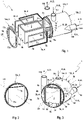
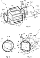
- the humidifier 1 shows an exploded view of a humidifier 1 according to the invention in a first embodiment.
- the humidifier 1 is provided for a fuel cell system for humidifying a dry cathode supply air K-ZL with a moist cathode exhaust air K-AL.
- the fuel cell system can be designed in a manner known to those skilled in the art and is not explained in more detail here. Understandably, only those fuel cell systems come into question in which the humidifier 1 can be used appropriately.
- the humidifier 1 extends in the longitudinal direction LR and has a housing 2 , a membrane block 3 and a sealing arrangement 4 .
- the sealing arrangement 4 is formed from exactly three mutually identical ring seals 5a, 5b, 5c.
- broken arrows/lines are used to indicate elements that are not immediately visible and/or only partially visible.
- the housing 2 has a hollow-cylindrical housing body 13c and two housing bases 13a and 13b. Accordingly, the housing body 13c has a round cross section and the housing bases 13a and 13b each have a round shape adapted thereto. It goes without saying, however, that the cross section of the housing body 13c can also be oval or polygonal—that is, for example, square or rectangular. Correspondingly, the housing bases 13a and 13b can have an oval or polygonal shape--that is, for example, square or rectangular.
- the housing body 13c is aligned in the longitudinal direction LR, and the housing bases 13a and 13b seal the housing body 13c in an airtight manner, axially with respect to the longitudinal direction LR.
- the housing body 13c is therefore sealed airtight at the longitudinal end side with the housing bottoms 13a and 13b.
- the housing bottom 13b is formed in one piece with the housing body 13a and the housing bottom 13a is firmly connected to the housing body 13c.
- the housing bottom 13a can be glued or welded to the housing body 13c, for example.
- the membrane block 3 is cuboid and has two airtight and opposite end faces 6a, 6b and four flow-through faces 7a, 7b, 7c, 7d.
- the membrane block 3 is accommodated in the housing 2 in such a way that the end faces 6a, 6b face the housing bottoms 13a, 13b and the flow-through faces 7a, 7b, 7c, 7d face the housing body 13c.
- the through-flow surfaces 7a, 7b, 7c, 7d are parallel and the end surfaces 6a and 6b are aligned transversely to the longitudinal direction LR.
- An air chamber 8a, 8b, 8c, 8d is formed between the respective flow-through surface 7a, 7b, 7c, 7d of the membrane block 3 and an opposite area of the housing 2 or the housing body 13c.
- the respective air chamber 8a, 8b, 8c, 8d is connected via a connection piece 14a, 14b, 14c, 14d to the outside in an air-conducting manner.
- the air chamber 8a is provided for supplying the cathode supply air K-ZL to the flow-through surface 7a via the connection piece 14a and the opposite air chamber 8b is provided for discharging the cathode supply air K-ZL from the flow-through surface 7b via the connection piece 14b.
- the air chamber 8c is provided for supplying the cathode exhaust air K-AL to the through-flow area 7c via the connection piece 14c and the opposite air chamber 8d is provided for discharging the cathode exhaust air K-AL from the through-flow area 7d via the connection piece 14d.
- the supply and discharge of the cathode supply air K-ZL and the cathode exhaust air K-AL are indicated here and further with arrows.
- the membrane block 3 is formed from a plurality of membranes which are permeable to water or water vapor and airtight. In 1 and the membrane block 3 is also shown purely schematically. The exact design of the membrane block 3 is based on the following Figures 9-10 explained in more detail.
- the cathode supply air K-ZL from the through-flow area 7a to the through-flow area 7b and the cathode exhaust air K-AL from the through-flow area 7c to the through-flow area 7d are routed separately from one another.
- the cathode supply air K-ZL is dry and the cathode exhaust air K-AL is moist, so that within the membrane block 3 the dry cathode supply air K-ZL is moistened with the moist cathode exhaust air K-AL and the moist cathode exhaust air K-AL can be dehumidified by the dry cathode supply air K-ZL.
- the efficiency of the fuel cell system can be improved by humidifying the dry cathode supply air K-ZL.
- the respective air chambers 8a, 8b, 8c, 8d are separated from one another in an airtight manner within the housing 2 by means of the sealing arrangement 4.
- the sealing arrangement 4 in the first embodiment of the humidifier 1 has exactly three ring seals 5a, 5b, 5c.
- the respective ring seal 5a, 5b, 5c is assigned to the respective flow-through surface 7a, 7b, 7c and runs around the respective flow-through surface 7a, 7b, 7c at the edge or along and at a distance from the connecting edges of the membrane block 3.
- the respective ring seal 5a, 5b, 5c lies flat or even on the respective flow-through surface 7a, 7b, 7c, so that the respective ring seal 5a, 5b, 5c does not bend or bend over the connecting edges of the membrane block 3.
- the exact design of the respective ring seal 5a, 5b, 5c is based on the following Figures 6-8 explained in more detail.
- An internal support structure 10 is formed within the housing body 13c, in which the membrane block 3 is accommodated in a rotationally fixed manner.
- the support structure 10 has three frame-like sealing surfaces 11a, 11b, 11c for the respective ring seals 5a, 5b, 5c or for the respective flow-through surfaces 7a, 7b, 7c.
- the frame-like sealing surfaces 11a, 11b, 11c are connected to the housing 2 at the edge in an airtight manner.
- the sealing surfaces 11a, 11b, 11c are formed in one piece with the housing body 13c and the housing base 13b and are firmly connected to the housing base 13a in an airtight manner.
- the support structure 10 comprises four support ribs 12, which support the membrane block 3 on the flow-through surface 7d.
- the sealing surfaces 11a, 11b, 11c form an inner cage 20 open on one side in the housing 2.
- the respective annular seal 5a, 5b, 5c is arranged in a sealing manner between the respective sealing surface 11a, 11b, 11c and the respective flow-through surface 7a, 7b and 7c.
- the respective ring seal 5a, 5b, 5c with the associated Flow-through surface 7a, 7b, 7c glued or welded and pressed against the associated sealing surface 11a, 11b, 11c.
- the exact configuration of the support structure 10 is explained below with reference to FIG 4 explained in more detail.
- the sealing arrangement 4 separates the air chambers 8a, 8b, 8c from one another, from the air chamber 8d and from the two end air chambers 9a, 9b in an airtight manner.
- the air chamber 8d is connected to the forehead air chambers 9a, 9b in an air-conducting manner and thus also in a pressure-equalizing manner.
- inflation of the membrane block 3 during operation of the humidifier 1 can advantageously be avoided. Since the air chamber 8d is provided for discharging the cathode exhaust air K-AL from the membrane block 3, this has the lowest pressure level when the humidifier 1 is in operation.
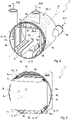
- 2 13 shows a bottom view of the case 13a in the humidifier 1 in the first embodiment.
- grooves 15a, 15b, 15c can be seen in the housing base 13a for the sealing surfaces 11a, 11b, 11c.
- the sealing surfaces 11a, 11b, 11c are airtightly connected to the housing cover 13a, for example glued or welded.
- the housing base 13a thus axially closes the housing body 13c in an airtight manner.
- the air chambers 8a, 8b, 8c are individually sealed and the air chamber 8d and the front air chamber 9a are sealed together in an axially airtight manner.
- FIG. 3 shows a view of the humidifier 1 in the first embodiment without the housing bottom 13a.
- the membrane block 3 is supported in the housing 2 transversely to the longitudinal direction LR by the support structure 10 and in the longitudinal direction LR by the two housing bases 13a and 13b.
- the air spaces 8a, 8b, 8c, 8d and the respective forehead air chamber 6a or 6b are adjacent transversely to the longitudinal direction LR and do not intersect or overlap.
- the air-guiding and pressure-equalizing connection between the air chamber 8d and the respective forehead air chamber 9a or 9b due to the missing sealing surface of the support structure 10 - compare to this 13 - is realized.
- FIG. 4 1 is a view of the housing 2 of the humidifier 1 in the first embodiment without the housing bottom 13a.
- additional ribs 16a, 16b, 16c can be seen on the sealing surfaces 11a, 11b, 11c of the support structure 10, which additionally support the membrane block 3 on the flow-through surfaces 7a, 7b, 7c.
- figure 5 12 shows a sectional view of the humidifier 1 in the first embodiment.
- the arrangement of the ring seals 5a, 5b, 5c at the edge on the through-flow surfaces 7a, 7b, 7c can be seen in particular.
- the exact design of the ring seals 5a, 5b, 5c is based on the following Figures 6-8 explained in more detail.
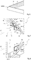
- the respective ring seal 5a, 5b, 5c has a sealing frame 17 and a sealing lip 18 which protrudes from the sealing frame 17.
- the sealing lip 18 is designed to be inclined inwards or towards the center of the respective annular seal 5a, 5b, 5c or towards the center of the respective flow-through surface 7a, 7b, 7c.
- the respective ring seal 5a, 5b, 5c is designed to be planar or flat.
- the sealing frame 17 of the respective ring seal 5a, 5b, 5c is materially connected to the associated flow area 7a, 7b, 7c.
- the respective sealing lip 18 is connected to the housing 2 or to the housing body 13c or aligned with the support structure 10 or with the respective sealing surface 11a, 11b, 11c and is in sealing contact with the housing 2 or with the housing body 13c or with the support structure 10 or with the respective sealing surface 11a, 11b, 11c.
- the respective ring seal 5a, 5b, 5c surrounds the respective flow area 7a, 7b, 7c at the edge, so that the connecting edges of the membrane block 3 remain free. In particular, this advantageously avoids angling or buckling of the respective annular seal 5a, 5b, 5c over the connecting edges of the diaphragm block 3.
- the structure of the sealing arrangement 4 is simplified overall.
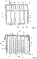
- 9 shows a view and 10 shows a sectional view of the membrane block 3 with ring seals 5a, 5b, 5c.
- the membranes 19 of the membrane block 3 can now be seen, which are aligned transversely to the longitudinal direction LR and arranged or stacked at a distance from one another.
- the membranes 19 are formed from a material that is permeable to water or water vapor and airtight.
- the cathode supply air K-ZL and the cathode exhaust air K-AL are routed between the individual membranes 19 .
- spaces formed between the individual membranes 19 on the flow-through surfaces 7a, 7b, 7c, 7d are closed by frames 21 in such a way that the cathode supply air K-ZL exclusively from the flow-through surface 7a to the flow-through surface 7b and the cathode exhaust air K-AL can flow exclusively from the through-flow area 7c to the through-flow area 7d.
- the cathode supply air K-ZL and the cathode exhaust air K-AL can exchange water or water vapor with one another via the membranes 19 .
- the dry cathode supply air K-ZL can be humidified by the moist cathode exhaust air K-AL.
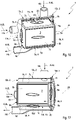
- 11 shows an exploded view of the humidifier according to the invention in a second embodiment.
- 12 shows a view of the housing base 13a in the in 11 shown humidifier.
- 13 shows a view of the in 11 shown humidifier without the housing base 13a.
- 14 shows a view of the housing 2 of FIG 11 shown humidifier without the housing base 13a.
- 15 shows a view of the in 11 shown humidifier 1 without the housing base 13a.
- 16 and 17 12 show sectional views of the humidifier 1 in the second embodiment.
- the sealing arrangement 4 in the second embodiment of the humidifier 1 has exactly four ring seals 5a, 5b, 5c, 5d.
- the flow-through surface 7d of the membrane block 3 is assigned a further ring seal 5d.
- the ring seals 5a, 5b, 5c, 5d in the second embodiment are identical to each other and to the ring seals 5a, 5b, 5c in the first embodiment.
- the support structure 10 has a further sealing surface 11d for the ring seal 5d, which is shaped identically to the sealing surfaces 11a, 11b, 11c.
- the sealing surfaces 11a, 11b, 11c, 11d form the four-sided inner cage 20 in the housing 2.
- a further additional rib 16d is also provided for supporting the diaphragm block 3 on the flow-through surface 7d.
- the flow-through surface 7d is supported in the housing 2 by the sealing surface 11d and the additional rib 16d, so that the supporting ribs 12 are no longer necessary according to the first embodiment and are not provided in the second embodiment.
- the annular seal 5d is arranged in a sealing manner between the flow-through surface 7d and the sealing surface 11d.
- the ring seal 5d additionally seals the air chamber 8d from the air chambers 8a, 8b, 8c. Nevertheless, the air chamber 8d is connected to the two forehead air chambers 9a and 9b in an air-conducting and thus pressure-equalizing manner.
- a further groove 15d for the sealing surface 11d is provided in the housing bottom 13a.
- the housing base 13a axially closes the housing body 13c in an airtight manner.
- the air chambers 8a, 8b, 8c, 8d and the front air chamber 9a are individually sealed in an airtight manner in the axial direction.
Landscapes
- Chemical & Material Sciences (AREA)
- Chemical Kinetics & Catalysis (AREA)
- Fuel Cell (AREA)
Abstract
Description
- Die Erfindung betrifft einen Befeuchter für ein Brennstoffzellensystem nach dem Obergriff des Anspruchs 1.
- Ein Befeuchter für ein Brennstoffzellensystem ist beispielweise aus der
DE 10 2013 020 503 A1 bekannt. In dem Befeuchter wird dabei eine trockene Kathoden-Zuluft durch eine feuchte Kathoden-Abluft befeuchtet und dadurch die Effizienz des Brennstoffzellensystems verbessert. Der Befeuchter weist dabei üblicherweise einen quaderförmigen Membranbock aus mehreren wasser- bzw. wasserdampfdurchlässigen Membranen und ein Gehäuse auf, in dem der Membranblock aufgenommen ist. In dem Membranblock werden die Kathoden-Zuluft und die Kathoden-Abluft getrennt voneinander geführt, wobei das Wasser bzw. der Wasserdampf über die Membranen des Membranblocks aus der feuchten Kathoden-Abluft in die trockene Kathoden-Zuluft übertragen wird. - Das Zuleiten und das Ableiten der Kathoden-Zuluft und der Kathoden-Abluft zu/aus dem Membranblock erfolgt üblicherweise an Durchströmungsflächen. Aufbaubedingt weist der Membranblock vier Durchströmungsflächen, die den Umfang des Membranblocks bilden, und zwei luftdichte Stirnflächen, die den Membranblock stirnseitig verschließen, auf. Den jeweiligen Durchströmungsflächen sind innerhalb des Gehäuses Luftkammern zum Zuleiten und zum Ableiten der Kathoden-Zuluft und der Kathoden-Abluft zugeordnet, die zweckgemäß voneinander luftdicht getrennt sind. Dazu wird öfters eine ein- oder mehrteilige Dichtanordnung verwendet, die die Durchströmungsflächen entlang deren Verbindungskanten miteinander und an den Stirnflächen voneinander abdichtet. Die Dichtanordnung ist dabei komplex aufgebaut und aufwändig in der Herstellung und Montage.
- Die Aufgabe der Erfindung ist es daher, für einen Befeuchter der gattungsgemäßen Art eine verbesserte oder zumindest alternative Ausführungsform anzugeben, bei der die beschriebenen Nachteile überwunden werden.
- Diese Aufgabe wird erfindungsgemäß durch den Gegenstand des unabhängigen Anspruchs 1 gelöst. Vorteilhafte Ausführungsformen sind Gegenstand der abhängigen Ansprüche.
- Ein Befeuchter ist für ein Brennstoffzellensystem zum Befeuchten einer trockenen Kathoden-Zuluft mit einer feuchten Kathoden-Abluft vorgesehen. Bei dem Befeuchter handelt es sich insbesondere um einen Membran-Befeuchter. Der Befeuchter weist dabei ein Gehäuse, einen Membranblock und eine Dichtanordnung auf. Der Membranblock ist quaderförmig und weist zwei luftdicht verschlossene und einander gegenüberliegende Stirnflächen und vier Durchströmungsflächen auf. Der Membranblock ist dabei so in dem Gehäuse aufgenommen, dass zwischen der jeweiligen Durchströmungsfläche des Membranblocks und einem gegenüberliegenden Bereich des Gehäuses jeweils eine Luftkammer zum Zuleiten oder zum Ableiten der Kathoden-Abluft oder der Kathoden-Zuluft zu/aus dem Membranblock gebildet ist. Die jeweiligen Luftkammern sind innerhalb des Gehäuses mittels der Dichtanordnung luftdicht voneinander getrennt. Erfindungsgemäß ist die Dichtanordnung aus drei oder vier voneinander separaten Ringdichtungen gebildet, wobei die jeweilige Ringdichtung jeweils einer der Durchströmungsflächen des Membranblocks zugeordnet ist. Die jeweilige Ringdichtung umläuft dabei die jeweilige zugeordnete Durchströmungsfläche randseitig und ist zwischen der jeweiligen Durchströmungsfläche und dem Gehäuse dichtend angeordnet.
- Die Dichtanordnung ist ausschließlich aus drei oder vier Ringdichtungen bzw. aus genau drei oder genau vier Ringdichtungen gebildet. Die Dichtanordnung weist demnach keine weiteren separaten Elemente zum Abdichten des Membranblocks zu dem Gehäuse auf. Dadurch ist die Dichtanordnung besonders einfach ausgeführt. Die jeweiligen Ringdichtungen sind separat voneinander bzw. physisch voneinander getrennt und umlaufen dabei randseitig ausschließlich die zugeordnete Durchströmungsfläche bzw. schließen ausschließlich die zugeordnete Durchströmungsfläche ein. Die jeweilige Ringdichtung liegt also ausschließlich auf der zugeordneten Durchströmungsfläche und ist flach bzw. eben ausgebildet. Insbesondere ist dabei eine Abwinklung bzw. ein Abknicken der jeweiligen Ringdichtung über die Verbindungskanten des Membranblocks vermieden. Anders formuliert, überbrücken die jeweiligen Ringdichtungen die Verbindungskanten des Membranblocks nicht. Vorteilhaftweise ist eine derartige flach bzw. eben liegende Ringdichtung vereinfacht und kostengünstig herstellbar. Dadurch ist die Dichtanordnung einfach aufgebaut und daher vereinfacht herstellbar und montierbar.
- Bei einer vorteilhaften Weiterbildung des Befeuchters kann vorgesehen sein, dass das Gehäuse eine innenliegende Stützstruktur aufweist. Der Membranblock kann durch die Stützstruktur vorteilhafterweise dreh- und verschiebefest in dem Gehäuse positioniert sein. Die jeweiligen Ringdichtungen sind zwischen den jeweiligen Durchströmungsflächen des Membranblocks und der Stützstruktur des Gehäuses dichtend angeordnet. Dazu kann die Stützstruktur Dichtflächen aufweisen, an denen die jeweiligen Ringdichtungen dichtend angeordnet sind. Zudem kann die Stützstruktur auch Zusatzrippen bzw. Zusatzflächen zum Abstützen des Membranblocks an den Durchströmungsflächen und/oder an den Stirnflächen aufweisen. Insbesondere können die Zusatzrippen bzw. Zusatzflächen zur Vermeidung von Schwingungen des Membranblocks im Betrieb des Befeuchters beitragen. Es versteht sich, dass die Stützstruktur und der Membranblock scheuergeschützt aneinander angeordnet sind.
- Vorteilhafterweise kann die Stützstruktur durch einen quaderförmigen bereichsweise offenen Innenkäfig gebildet und der Membranblock in dem Innenkäfig aufgenommen sein. Die jeweiligen Ringdichtungen können dabei zwischen den jeweiligen Durchströmungsflächen des Membranblocks und dem Innenkäfig dichtend angeordnet sein.
- Bei einer vorteilhaften Weiterbildung des Befeuchters kann vorgesehen sein, dass die Ringdichtung einen Dichtrahmen und eine von dem Dichtrahmen abstehende Dichtlippe aufweist. Der Dichtrahmen ist dabei von der Dichtlippe abgewandt mit der zugeordneten Durchströmungsfläche stoffschlüssig verbunden. Vorzugsweise ist der Dichtrahmen mit der zugeordneten Durchströmungsfläche verklebt oder verschweißt. Die Dichtlippe ist dann zu dem Gehäuse zugewandt angeordnet und liegt an dem Gehäuse dichtend an. Vorteilhafterweise kann die Dichtlippe nach innen bzw. zur Mitte der jeweiligen Ringdichtung hin geneigt ausgebildet sein. Bei der Montage des Befeuchters kann vorteilhafterweise die Dichtanordnung bzw. die jeweiligen Ringdichtungen auf dem Membranblock vormontiert bzw. befestigt sein und der Membranblock anschließend in dem Gehäuse angeordnet werden. Die Herstellung des Befeuchters kann dadurch deutlich vereinfacht werden.
- Vorteilhafterweise kann die jeweilige Ringdichtung die jeweilige zugeordnete Durchströmungsfläche des Membranblocks randseitig nach innen beabstandet umlaufen, so dass der jeweiligen Durchströmungsfläche zugeordnete Verbindungskanten frei liegen und die jeweilige Ringdichtung über die jeweiligen Verbindungskanten nicht übergeht. Mit anderen Worten ist eine Abwinklung bzw. ein Abknicken der jeweiligen Ringdichtung über die Verbindungskanten des Membranblocks sicher vermieden. Vorteilhafterweise kann die jeweilige Ringdichtung mit der jeweiligen zugeordneten Durchströmungsfläche stoffschlüssig verbunden, vorzugsweise verklebt oder verschweißt, sein.
- Vorteilhafterweise kann vorgesehen sein, dass das Gehäuse einen längsendseitig offenen Gehäusekörper und zwei Gehäuseböden aufweist. Dabei sind die jeweiligen Durchströmungsflächen des Membranblocks dem Gehäusekörper und die Stirnflächen des Membranblocks den Gehäuseböden zugewandt. Der jeweilige Gehäuseboden verschließt den Gehäusekörper längsendseitig und ist mit dem Gehäusekörper luftdicht fest verbunden. Der eine Gehäuseboden ist mit dem Gehäusekörper bevorzugt integral bzw. einstückig ausgeformt. Der andere Gehäuseboden ist mit dem Gehäusekörper bevorzugt verklebt oder verschweißt oder verschraubt.
- Bei einer vorteilhaften Ausführungsform des Befeuchters ist vorgesehen, dass zwischen den Durchströmungsflächen des Membranblocks und den gegenüberliegenden Bereichen des Gehäuses insgesamt vier Luftkammern und zwischen den Stirnflächen des Membranblocks und den gegenüberliegenden Bereichen des Gehäuses insgesamt zwei Stirnluftkammern gebildet sind. Die Dichtanordnung ist dabei aus genau drei Ringdichtungen gebildet, die voneinander separat bzw. physikalisch voneinander getrennt sind. Dabei sind drei der vier Luftkammern durch die drei Ringdichtungen voneinander und von der vierten Luftkammer und von den Stirnluftkammern luftdicht abgegrenzt. Die vierte Luftkammer ist dagegen mit den beiden Stirnluftkammern luftleitend und dadurch druckausgleichend verbunden. Bei dieser vorteilhaften Ausführungsform des Befeuchters ist die Anzahl der Ringdichtungen minimiert, so dass die Dichtanordnung besonders einfach ausgeführt und das Abdichten des Befeuchters besonders vereinfacht ist.
- Bei einer alternativen Ausführungsform des Befeuchters ist vorgesehen, dass zwischen den Durchströmungsflächen des Membranblocks und den gegenüberliegenden Bereichen des Gehäuses insgesamt vier Luftkammern und zwischen den Stirnflächen des Membranblocks und den gegenüberliegenden Bereichen des Gehäuses insgesamt zwei Stirnluftkammern gebildet sind. Die Dichtanordnung ist dabei aus genau vier Ringdichtungen gebildet, die voneinander separat bzw. physikalisch voneinander getrennt sind. Die vier Luftkammern sind durch die vier Ringdichtungen voneinander luftdicht abgegrenzt. Zudem sind drei der vier Luftkammern durch die Ringdichtungen von den beiden Stirnluftkammern luftdicht abgegrenzt. Die vierte Luftkammer ist dagegen mit den beiden Stirnluftkammern luftleitend und dadurch druckausgleichend verbunden.
- In beiden Ausführungsformen des Befeuchters verhindert eine druckausgleichende Verbindung der vierten Luftkammer und den beiden Stirnluftkammern ein Aufblähen des Membranblocks im Betrieb des Befeuchters. Die vierte Luftkammer ist vorzugsweise zum Ableiten der Kathoden-Abluft aus dem Membranblock vorgesehen und weist im Betrieb des Befeuchters das niedrigste Druckniveau auf.
- Weitere wichtige Merkmale und Vorteile der Erfindung ergeben sich aus den Unteransprüchen, aus den Zeichnungen und aus der zugehörigen Figurenbeschreibung anhand der Zeichnungen.
- Es versteht sich, dass die vorstehend genannten und die nachstehend noch zu erläuternden Merkmale nicht nur in der jeweils angegebenen Kombination, sondern auch in anderen Kombinationen oder in Alleinstellung verwendbar sind, ohne den Rahmen der vorliegenden Erfindung zu verlassen.
- Bevorzugte Ausführungsbeispiele der Erfindung sind in den Zeichnungen dargestellt und werden in der nachfolgenden Beschreibung näher erläutert, wobei sich gleiche Bezugszeichen auf gleiche oder ähnliche oder funktional gleiche Komponenten beziehen.
- Es zeigen, jeweils schematisch
- Fig. 1
- eine Explosionsansicht eines erfindungsgemäßen Befeuchters in einer ersten Ausführungsform;
- Fig. 2
- eine Ansicht eines Gehäusebodens in dem in
Fig. 1 gezeigten Befeuchter; - Fig. 3
- eine Ansicht des in
Fig. 1 gezeigten Befeuchters ohne einen der Gehäuseböden; - Fig. 4
- eine Ansicht eines Gehäuses des in
Fig. 1 gezeigten Befeuchters ohne einen der Gehäuseböden; - Fig. 5
- eine Schnittansicht des in
Fig. 1 gezeigten Befeuchters; - Fig. 6
- eine teilweise Ansicht einer Ringdichtung des in
Fig. 1 gezeigten Befeuchters; - Fig. 7 und 8
- vergrößerte Schnittansichten des in
Fig. 1 gezeigten Befeuchters ausFig. 5 ; - Fig. 9 und 10
- eine Ansicht und eine Schnittansicht eines Membranblocks des in
Fig. 1 gezeigten Befeuchters mit Ringdichtungen; - Fig. 11
- eine Explosionsansicht des erfindungsgemäßen Befeuchters in einer zweiten Ausführungsform;
- Fig. 12
- eine Ansicht des Gehäusebodens in dem in
Fig. 11 gezeigten Befeuchter; - Fig. 13
- eine Ansicht des in
Fig. 11 gezeigten Befeuchters ohne einen der Gehäuseböden; - Fig. 14
- eine Ansicht des Gehäuses des in
Fig. 11 gezeigten Befeuchters ohne einen der Gehäuseböden; - Fig. 15
- eine Ansicht des in
Fig. 11 gezeigten Befeuchters ohne einen der Gehäuseböden; - Fig. 16 und 17
- teilweise Schnittansichten des in
Fig. 11 gezeigten Befeuchters. -
Fig. 1 zeigt eine Explosionsansicht eines erfindungsgemäßen Befeuchters 1 in einer ersten Ausführungsform. Der Befeuchter 1 ist für ein Brennstoffzellensystem zum Befeuchten einer trockenen Kathoden-Zuluft K-ZL mit einer feuchten Kathoden-Abluft K-AL vorgesehen. Das Brennstoffzellensystem kann auf eine dem Fachmann bekannte Weise ausbildet sein und wird hier nicht näher erläutert. Verständlicherweise kommen dabei nur die Brennstoffzellensysteme in Frage, in denen der Befeuchter 1 zweckgemäß anwendbar ist. Der Befeuchter 1 erstreckt sich in Längsrichtung LR und weist ein Gehäuse 2, einen Membranblock 3 und eine Dichtanordnung 4 auf. In der ersten Ausführungsform des Befeuchters 1 ist die Dichtanordnung 4 aus genau drei zueinander identischen Ringdichtungen 5a, 5b, 5c gebildet. InFig. 1 und auch weiter sind zum Kennzeichnen von nicht unmittelbar sichtbaren und/oder nur teilweise sichtbaren Elementen durchbrochene Pfeile/Linien verwendet. - Das Gehäuse 2 weist einen hohlzylindrischen Gehäusekörper 13c und zwei Gehäuseböden 13a und 13b auf. Demnach weisen der Gehäusekörper 13c einen runden Querschnitt und die Gehäuseböden 13a und 13b jeweils eine darauf angepasste runde Form auf. Es versteht sich jedoch, dass der Querschnitt des Gehäusekörpers 13c auch oval oder vieleckig - also beispielweise quadratisch oder rechteckig - sein kann. Entsprechend können die Gehäuseböden 13a und 13b eine ovale oder vieleckige - also beispielweise quadratische oder rechteckige - Form aufweisen. Der Gehäusekörper 13c ist in Längsrichtung LR ausgerichtet und die Gehäuseböden 13a und 13b verschließen luftdicht den Gehäusekörper 13c axial zur Längsrichtung LR. Der Gehäusekörper 13c ist also längsendseitig mit den Gehäuseböden 13a und 13b luftdicht verschlossen. Dabei ist der Gehäuseboden 13b einstückig mit dem Gehäusekörper 13a ausgeformt und der Gehäuseboden 13a ist mit dem Gehäusekörper 13c festverbunden. Der Gehäuseboden 13a kann mit dem Gehäusekörper 13c beispielweise verklebt oder verschweißt sein.
- Der Membranblock 3 ist quaderförmig und weist zwei luftdicht verschlossene und einander gegenüberliegende Stirnflächen 6a, 6b und vier Durchströmungsflächen 7a, 7b, 7c, 7d auf. Der Membranblock 3 ist dabei so in dem Gehäuse 2 aufgenommen, dass die Stirnflächen 6a, 6b den Gehäuseböden 13a, 13b und die Durchströmungsflächen 7a, 7b, 7c, 7d dem Gehäusekörper 13c zugewandt sind. Dadurch sind die Durchströmungsflächen 7a, 7b, 7c, 7d parallel und die Stirnflächen 6a und 6b quer zur Längsrichtung LR ausgerichtet.
- Zwischen der jeweiligen Durchströmungsfläche 7a, 7b, 7c, 7d des Membranblocks 3 und einem gegenüberliegenden Bereich des Gehäuses 2 bzw. des Gehäusekörpers 13c ist jeweils eine Luftkammer 8a, 8b, 8c, 8d gebildet. Zwischen den Stirnflächen 6a, 6b und den Gehäuseböden 13a, 13b sind Stirnluftkammern 9a, 9b - in Form von zwei quer zur Längsrichtung ausgerichteten Luftspalte - gebildet. Die jeweilige Luftkammer 8a, 8b, 8c, 8d ist über jeweils einen Stutzen 14a, 14b, 14c, 14d nach außen luftleitend verbunden.
- Die Luftkammer 8a ist dabei zum Zuleiten der Kathoden-Zuluft K-ZL zu der Durchströmungsfläche 7a über den Stutzen 14a und die gegenüberliegende Luftkammer 8b ist zum Ableiten der Kathoden-Zuluft K-ZL von der Durchströmungsfläche 7b über den Stutzen 14b vorgesehen. Die Luftkammer 8c ist zum Zuleiten der Kathoden-Abluft K-AL zu der Durchströmungsfläche 7c über den Stutzen 14c und die gegenüberliegende Luftkammer 8d ist zum Ableiten der Kathoden-Abluft K-AL von der Durchströmungsfläche 7d über den Stutzen 14d vorgesehen. Das Zuleiten und das Ableiten der Kathoden-Zuluft K-ZL und der Kathoden-Abluft K-AL sind hier und weiter mit Pfeilen angedeutet.
- Der Membranblock 3 ist aus mehreren Membranen gebildet, die wasser- bzw. wasserdampfdurchlässig und luftdicht sind. In
Fig. 1 und auch weiter ist der Membranblock 3 rein schematisch gezeigt. Die genaue Ausgestaltung des Membranblocks 3 wird im Folgenden anhandFig. 9-10 näher erläutert. In dem Membranblock 3 werden die Kathoden-Zuluft K-ZL von der Durchströmungsfläche 7a zu der Durchströmungsfläche 7b und die Kathoden-Abluft K-AL von der Durchströmungsfläche 7c zu der Durchströmungsfläche 7d getrennt voneinander geführt. Die Kathoden-Zuluft K-ZL ist trocken und die Kathoden-Abluft K-AL ist feucht, so dass innerhalb des Membranblocks 3 die trockene Kathoden-Zuluft K-ZL mit der feuchten Kathoden-Abluft K-AL befeuchtet und die feuchte Kathoden-Abluft K-AL durch die trockene Kathoden-Zuluft K-ZL entfeuchtet werden kann. Durch die Befeuchtung der trockene Kathoden-Zuluft K-ZL kann die Effizienz des Brennstoffzellensystems verbessert werden. - Die jeweiligen Luftkammern 8a, 8b, 8c, 8d sind innerhalb des Gehäuses 2 mittels der Dichtanordnung 4 luftdicht voneinander getrennt. Wie oben bereits erwähnt, weist die Dichtanordnung 4 in der ersten Ausführungsform des Befeuchters 1 genau drei Ringdichtungen 5a, 5b, 5c auf. Die jeweilige Ringdichtung 5a, 5b, 5c ist der jeweiligen Durchströmungsfläche 7a, 7b, 7c zugeordnet und umläuft die jeweilige Durchströmungsfläche 7a, 7b, 7c randseitig bzw. entlang und beabstandet zu den Verbindungskanten des Membranblocks 3. Auf der Durchströmungsfläche 7d ist dagegen keine Ringdichtung angeordnet. Die jeweilige Ringdichtung 5a, 5b, 5c liegt auf der jeweiligen Durchströmungsfläche 7a, 7b, 7c flach bzw. eben, so dass eine Abwinklung bzw. ein Abknicken der jeweiligen Ringdichtung 5a, 5b, 5c über die Verbindungskanten des Membranblocks 3 vermieden ist. Die genaue Ausgestaltung der jeweiligen Ringdichtung 5a, 5b, 5c wird im Folgenden anhand
Fig. 6-8 näher erläutert. - Innerhalb des Gehäusekörpers 13c ist eine innenliegende Stützstruktur 10 ausgeformt, in der der Membranblock 3 drehfest aufgenommen ist. Die Stützstruktur 10 weist dabei drei rahmenartige Dichtflächen 11a, 11b, 11c für die jeweiligen Ringdichtungen 5a, 5b, 5c bzw. für die jeweiligen Durchströmungsflächen 7a, 7b, 7c auf. Die rahmenartigen Dichtflächen 11a, 11b, 11c sind dabei randseitig luftdicht mit dem Gehäuse 2 verbunden. So sind die Dichtflächen 11a, 11b, 11c mit dem Gehäusekörper 13c und dem Gehäuseboden 13b einstückig ausgeformt und mit dem Gehäuseboden 13a luftdicht festverbunden. Ferner umfasst die Stützstruktur 10 vier Stützrippen 12, die den Membranblock 3 an der Durchströmungsfläche 7d abstützen. Die Dichtflächen 11a, 11b, 11c bilden in dem Gehäuse 2 einen einseitig offenen Innenkäfig 20.
- Die jeweilige Ringdichtung 5a, 5b, 5c ist zwischen der jeweiligen Dichtfläche 11a, 11b, 11c und der jeweiligen Durchströmungsfläche 7a, 7b und 7c dichtend angeordnet. Dazu ist die jeweilige Ringdichtung 5a, 5b, 5c mit der zugeordneten Durchströmungsfläche 7a, 7b, 7c verklebt oder verschweißt und an die zugeordnete Dichtfläche 11a, 11b, 11c angepresst. Die genaue Ausgestaltung der Stützstruktur 10 wird im Folgenden anhand
Fig. 4 näher erläutert. - In dem Gehäuse 2 sind durch die Dichtanordnung 4 die Luftkammern 8a, 8b, 8c voneinander, von der Luftkammer 8d und von den beiden Stirnluftkammern 9a, 9b luftdicht getrennt. Die Luftkammer 8d ist dagegen luftleitend und dadurch auch druckausgleichend mit den Stirnluftkammern 9a, 9b verbunden. Dadurch kann ein Aufblähen des Membranblocks 3 im Betrieb des Befeuchters 1 vorteilhaft vermieden werden. Da die Luftkammer 8d zum Ableiten der Kathoden-Abluft K-AL aus dem Membranblock 3 vorgesehen ist, weist diese im Betrieb des Befeuchters 1 das niedrigste Druckniveau auf.
-
Fig. 2 zeigt eine Ansicht des Gehäusebodens 13a in dem Befeuchter 1 in der ersten Ausführungsform. InFig. 2 sind insbesondere Rillen 15a, 15b, 15c in dem Gehäuseboden 13a für die Dichtflächen 11a, 11b, 11c erkennbar. Innerhalb der Rillen 15a, 15b, 15c werden die Dichtflächen 11a, 11b, 11c luftdicht mit dem Gehäusedeckel 13a festverbunden, beispielsweise verklebt oder verschweißt. Der Gehäuseboden 13a verschließt also axial den Gehäusekörper 13c luftdicht. Dabei werden die Luftkammern 8a, 8b, 8c einzelnen und die Luftkammer 8d und die Stirnluftkammer 9a gemeinsam axial luftdicht verschlossen. -
Fig. 3 zeigt eine Ansicht des Befeuchters 1 in der ersten Ausführungsform ohne den Gehäuseboden 13a. Wie inFig. 3 besonders gut erkennbar, ist der Membranblock 3 in dem Gehäuse 2 quer zur Längsrichtung LR durch die Stützstruktur 10 und in Längsrichtung LR durch die beiden Gehäuseböden 13a und 13b abgestützt. InFig. 3 ist zudem erkennbar, dass die Lufträume 8a, 8b, 8c, 8d und die jeweilige Stirnluftkammer 6a bzw. 6b quer zur Längsrichtung LR benachbart sind und sich nicht überschneiden bzw. überlappen. Ferner ist erkennbar, dass die luftleitende und druckausgleichende Verbindung zwischen der Luftkammer 8d und der jeweiligen Stirnluftkammer 9a bzw. 9b durch die fehlende Dichtfläche der Stützstruktur 10 - vergleiche dazuFig. 13 - realisiert ist. - In
Fig. 4 ist eine Ansicht des Gehäuses 2 des Befeuchters 1 in der ersten Ausführungsform ohne den Gehäuseboden 13a gezeigt. Hier sind insbesondere Zusatzrippen 16a, 16b, 16c an den Dichtflächen 11a, 11b, 11c der Stützstruktur 10 erkennbar, die den Membranblock 3 an den Durchströmungsflächen 7a, 7b, 7c zusätzlich abstützen. -
Fig. 5 zeigt eine Schnittansicht des Befeuchters 1 in der ersten Ausführungsform. InFig. 5 ist insbesondere die randseitige Anordnung der Ringdichtungen 5a, 5b, 5c an den Durchströmungsflächen 7a, 7b, 7c erkennbar. Die genaue Ausgestaltung der Ringdichtungen 5a, 5b, 5c wird im Folgenden anhandFig. 6-8 näher erläutert. -
Fig. 6 zeigt nun eine teilweise Ansicht einer der jeweiligen zueinander identischen Ringdichtungen 5a, 5b, 5c. Die jeweilige Ringdichtung 5a, 5b, 5c weist dabei einen Dichtrahmen 17 und eine Dichtlippe 18 auf, die von dem Dichtrahmen 17 absteht. Die Dichtlippe 18 ist dabei nach innen bzw. zur Mitte der jeweiligen Ringdichtung 5a, 5b, 5c bzw. zur Mitte der jeweiligen Durchströmungsfläche 7a, 7b, 7c hin geneigt ausgebildet. Die jeweilige Ringdichtung 5a, 5b, 5c ist eben bzw. flach ausgebildet. -
Fig. 7 und Fig. 8 zeigen vergrößerte Ausschnitte ausFig. 5 . Wie hier erkennbar, ist der Dichtrahmen 17 der jeweiligen Ringdichtung 5a, 5b, 5c stoffschlüssig mit der zugeordneten Durchströmungsfläche 7a, 7b, 7c verbunden. Die jeweilige Dichtlippe 18 ist dabei zu dem Gehäuse 2 bzw. zu dem Gehäusekörper 13c bzw. zu der Stützstruktur 10 bzw. zu der jeweiligen Dichtfläche 11a, 11b, 11c ausgerichtet und liegt dichtend an dem Gehäuse 2 bzw. an dem Gehäusekörper 13c bzw. an der Stützstruktur 10 bzw. an der jeweiligen Dichtfläche 11a, 11b, 11c an. Dabei umläuft die jeweilige Ringdichtung 5a, 5b, 5c die jeweilige Durchströmungsfläche 7a, 7b, 7c randseitig, so dass die Verbindungskanten des Membranblocks 3 frei bleiben. Dadurch wird insbesondere eine Abwinklung bzw. ein Abknicken der jeweiligen Ringdichtung 5a, 5b, 5c über die Verbindungskanten des Membranblocks 3 vorteilhaft vermieden. Zudem ist der Aufbau der Dichtanordnung 4 insgesamt vereinfacht. -
Fig. 9 zeigt eine Ansicht undFig. 10 zeigt eine Schnittansicht des Membranblocks 3 mit Ringdichtungen 5a, 5b, 5c. InFig. 9 und Fig. 10 sind nun die Membranen 19 des Membranblocks 3 erkennbar, die quer zur Längsrichtung LR ausgerichtet und zueinander beabstandet angeordnet bzw. gestapelt sind. Die Membranen 19 sind dabei aus einem Material geformt, das wasser- bzw. wasserdampfdurchlässig und luftdicht ist. Zwischen den einzelnen Membranen 19 werden die Kathoden-Zuluft K-ZL und die Kathoden-Abluft K-AL geführt. Zweckgemäß sind zwischen den einzelnen Membranen 19 gebildete Zwischenräume an den Durchströmungsflächen 7a, 7b, 7c, 7d so durch Rahmen 21 geschlossen, dass die Kathoden-Zuluft K-ZL ausschließlich von der Durchströmungsfläche 7a zu der Durchströmungsfläche 7b und die Kathoden-Abluft K-AL ausschließlich von der Durchströmungsfläche 7c zu der Durchströmungsfläche 7d strömen kann. Über die Membranen 19 können die Kathoden-Zuluft K-ZL und die Kathoden-Abluft K-AL Wasser bzw. Wasserdampf miteinander austauschen. Dadurch kann die trockene Kathoden-Zuluft K-ZL durch die feuchte Kathoden-Abluft K-AL befeuchtet werden. -
Fig. 11 zeigt eine Explosionsansicht des erfindungsgemäßen Befeuchters in einer zweiten Ausführungsform.Fig. 12 zeigt eine Ansicht des Gehäusebodens 13a in dem inFig. 11 gezeigten Befeuchter.Fig. 13 zeigt eine Ansicht des inFig. 11 gezeigten Befeuchters ohne den Gehäuseboden 13a.Fig. 14 zeigt eine Ansicht des Gehäuses 2 des inFig. 11 gezeigten Befeuchters ohne den Gehäuseboden 13a.Fig. 15 zeigt eine Ansicht des inFig. 11 gezeigten Befeuchters 1 ohne den Gehäuseboden 13a.Fig. 16 und Fig. 17 zeigen Schnittansichten des Befeuchters 1 in der zweiten Ausführungsform. - Im Folgenden werden die Unterschiede der zweiten Ausführungsform in
Fig. 11-17 im Vergleich zu der ersten Ausführungsform inFig. 1-10 näher erläutert. - Bezugnehmend auf
Fig. 11, 13 und15-17 , weist die Dichtanordnung 4 in der zweiten Ausführungsform des Befeuchters 1 genau vier Ringdichtungen 5a, 5b, 5c, 5d auf. Anders formuliert, ist der Durchströmungsfläche 7d des Membranblocks 3 abweichend zu der ersten Ausführungsform des Befeuchters 1 eine weitere Ringdichtung 5d zugeordnet. Die Ringdichtungen 5a, 5b, 5c, 5d in der zweiten Ausführungsform sind zueinander und zu den Ringdichtungen 5a, 5b, 5c in der ersten Ausführungsform identisch. - Bezugnehmend auf
Fig. 14 , weist die Stützstruktur 10 eine weitere Dichtfläche 11d für die Ringdichtung 5d auf, die zu den Dichtflächen 11a, 11b, 11c identisch ausgeformt ist. Die Dichtflächen 11a, 11b, 11c, 11d bilden in dem Gehäuse 2 den vierseitigen Innenkäfig 20. Ferner ist eine weitere Zusatzrippe 16d zum Abstützen des Membranblocks 3 an der Durchströmungsfläche 7d vorgesehen. Die Durchströmungsfläche 7d ist in dem Gehäuse 2 durch die Dichtfläche 11d und die Zusatzrippe 16d abgestützt, so dass die Stützrippen 12 gemäß der ersten Ausführungsform nicht mehr notwendig und in der zweiten Ausführungsform nicht vorgesehen sind. - In
Fig. 16-17 sind zudem die Flächen eingekreist, an denen der Membranblock 3 in dem Gehäuse 2 durch die Zusatzrippen 16a, 16b, 16c, 16d und die beiden Gehäuseböden 13a und 13b zusätzlich und scheuerfrei abgestützt ist. - Bezugnehmend auf
Fig. 13 und15 , ist die Ringdichtung 5d zwischen der Durchströmungsfläche 7d und der Dichtfläche 11d dichtend angeordnet. Die Ringdichtung 5d dichtet dabei die Luftkammer 8d zusätzlich von den Luftkammern 8a, 8b, 8c ab. Dennoch ist die Luftkammer 8d luftleitend und dadurch druckausgleichend mit den beiden Stirnluftkammern 9a und 9b verbunden. - Bezugnehmend auf
Fig. 11 und 12 , ist in dem Gehäuseboden 13a eine weitere Rille 15d für die Dichtfläche 11d vorgesehen. Der Gehäuseboden 13a verschließt axial den Gehäusekörper 13c luftdicht. Dabei werden die Luftkammern 8a, 8b, 8c, 8d und die Stirnluftkammer 9a einzelnen axial luftdicht verschlossen. - Im Übrigen stimmt die zweite Ausführungsform des Befeuchters mit der ersten Ausführungsform des Befeuchters 1 in
Fig. 1-10 überein.
Claims (10)
- Befeuchter (1) für ein Brennstoffzellensystem zum Befeuchten einer trockenen Kathoden-Zuluft (K-ZL) mit einer feuchten Kathoden-Abluft (K-AL),- wobei der Befeuchter (1) ein Gehäuse (2), einen quaderförmigen Membranblock (3) und eine Dichtanordnung (4) aufweist,- wobei der Membranblock (3) zwei luftdicht verschlossene und einander gegenüberliegende Stirnflächen (6a,6b) und vier Durchströmungsflächen (7a,7b,7c,7d) aufweist,- wobei der Membranblock (3) in dem Gehäuse (2) so aufgenommen ist, dass zwischen der jeweiligen Durchströmungsfläche (7a,7b,7c,7d) des Membranblocks (3) und einem gegenüberliegenden Bereich des Gehäuses (2) jeweils eine Luftkammer (8a,8b,8c,8d) zum Zuleiten oder Ableiten der Kathoden-Abluft (K-AL) oder der Kathoden-Zuluft (K-ZL) zu/aus dem Membranblock (3) gebildet ist,- wobei die jeweiligen Luftkammern (8a,8b,8c,8d) innerhalb des Gehäuses (2) mittels der Dichtanordnung (4) luftdicht voneinander getrennt sind,dadurch gekennzeichnet,- dass die Dichtanordnung (4) aus drei oder vier voneinander separaten Ringdichtungen (5a,5b,5c,5d) gebildet ist, wobei die jeweilige Ringdichtung (5a,5b,5c,5d) jeweils einer der Durchströmungsflächen (7a,7b,7c,7d) des Membranblocks (3) zugeordnet ist, und- dass die jeweilige Ringdichtung (5a,5b,5c,5d) die jeweilige zugeordnete Durchströmungsfläche (7a,7b,7c,7d) randseitig umläuft und zwischen der jeweiligen Durchströmungsfläche (7a,7b,7c,7d) und dem Gehäuse (2) dichtend angeordnet ist.
- Befeuchter nach Anspruch 1,
dadurch gekennzeichnet,
dass das Gehäuse (2) eine innenliegende Stützstruktur (10) aufweist und die jeweiligen Ringdichtungen (5a,5b,5c,5d) zwischen den jeweiligen Durchströmungsflächen (7a,7b,7c,7d) des Membranblocks (3) und der Stützstruktur (10) des Gehäuses (2) dichtend angeordnet sind. - Befeuchter nach Anspruch 2,
dadurch gekennzeichnet,- dass die Stützstruktur (10) durch einen quaderförmigen bereichsweise offenen Innenkäfig (20) gebildet ist und der Membranblock (3) in dem Innenkäfig (20) aufgenommen ist, und- dass die jeweiligen Ringdichtungen (5a,5b,5c,5d) zwischen den jeweiligen Durchströmungsflächen (7a,7b,7c,7d) des Membranblocks (3) und dem Innenkäfig (20) dichtend angeordnet sind. - Befeuchter nach einem der Ansprüche 1 bis 3,
dadurch gekennzeichnet,
dass die jeweilige Ringdichtung (5a,5b,5c,5d) mit der jeweiligen zugeordneten Durchströmungsfläche (7a,7b,7c,7d) stoffschlüssig verbunden, vorzugsweise verklebt oder verschweißt, ist. - Befeuchter nach einem der Ansprüche 1 bis 4,
dadurch gekennzeichnet,- dass die Ringdichtung (5a,5b,5c,5d) einen Dichtrahmen (17) und eine von dem Dichtrahmen (17) abstehende Dichtlippe (18) aufweist,- dass der Dichtrahmen (17) von der Dichtlippe (18) abgewandt mit der zugeordneten Durchströmungsfläche (7a,7b,7c,7d) stoffschlüssig verbunden, vorzugsweise verklebt oder verschweißt, ist, und- dass die Dichtlippe (18) zu dem Gehäuse (2) gerichtet ist und an dem Gehäuse (2) dichtend anliegt. - Befeuchter nach einem der Ansprüche 1 bis 5,
dadurch gekennzeichnet,
dass die jeweilige Ringdichtung (5a,5b,5c,5d) die jeweilige zugeordnete Durchströmungsfläche (7a,7b,7c,7d) des Membranblocks (3) nach innen beabstandet umläuft, so dass der jeweiligen Durchströmungsfläche (7a,7b,7c,7d) zugeordnete Verbindungskanten frei liegen und die jeweilige Ringdichtung (5a,5b,5c,5d) über die jeweiligen Verbindungskanten nicht übergeht. - Befeuchter nach einem der Ansprüche 1 bis 6,
dadurch gekennzeichnet,- dass zwischen den Durchströmungsflächen (7a,7b,7c,7d) des Membranblocks (3) und den gegenüberliegenden Bereichen des Gehäuses (2) insgesamt vier Luftkammern (8a,8b,8c,8d) und zwischen den Stirnflächen (6a, 6b) des Membranblocks (3) und den gegenüberliegenden Bereichen des Gehäuses (2) insgesamt zwei Stirnluftkammern (9a, 9b) gebildet sind,- dass die Dichtanordnung (4) aus drei voneinander separaten Ringdichtungen (5a,5b,5c) gebildet ist, und- dass drei der vier Luftkammern (8a,8b,8c) durch die drei Ringdichtungen (5a,5b,5c) voneinander und von der vierten Luftkammer (8d) und von den Stirnluftkammern (9a, 9b) luftdicht abgegrenzt sind und die vierte Luftkammer (8d) mit den beiden Stirnluftkammern (9a, 9b) luftleitend und dadurch druckausgleichend verbunden ist. - Befeuchter nach einem der Ansprüche 1 bis 6,
dadurch gekennzeichnet,- dass zwischen den Durchströmungsflächen (7a,7b,7c,7d) des Membranblocks (3) und den gegenüberliegenden Bereichen des Gehäuses (2) insgesamt vier Luftkammern (8a,8b,8c,8d) und zwischen den Stirnflächen (6a, 6b) des Membranblocks (3) und den gegenüberliegenden Bereichen des Gehäuses (2) insgesamt zwei Stirnluftkammern (9a, 9b) gebildet sind,- dass die Dichtanordnung (4) aus vier voneinander separaten Ringdichtungen (5a,5b,5c,5d) gebildet ist,- dass die vier Luftkammern (8a,8b,8c,8d) durch die vier Ringdichtungen (5a,5b,5c,5d) voneinander luftdicht abgegrenzt sind, und- dass drei der vier Luftkammern (8a,8b,8c) durch die Ringdichtungen (5a,5b,5c) von den beiden Stirnluftkammern (9a, 9b) luftdicht abgegrenzt sind und die vierte Luftkammer (8d) mit den beiden Stirnluftkammern (9a, 9b) luftleitend und dadurch druckausgleichend verbunden ist. - Befeuchter nach Anspruch 7 oder 8,
dadurch gekennzeichnet,
dass die vierte Luftkammer (8d) zum Ableiten der feuchter Kathoden-Abluft (K AL) aus dem Membranblock (3) vorgesehen ist und im Betrieb des Befeuchters (1) das niedrigste Druckniveau aufweist. - Befeuchter nach einem der Ansprüche 1 bis 9,
dadurch gekennzeichnet,- dass das Gehäuse (2) einen längsendseitig offenen Gehäusekörper (13c) und zwei Gehäuseböden (13a, 13b) aufweist, wobei die jeweiligen Durchströmungsflächen (7a,7b,7c,7d) des Membranblocks (3) dem Gehäusekörper (13c) und die Stirnflächen (6a, 6b) des Membranblocks (3) den Gehäuseböden (13a, 13b) zugewandt sind, und- dass der jeweilige Gehäuseboden (13a, 13b) den Gehäusekörper (13c) längsendseitig verschließt und mit dem Gehäusekörper (13c) luftdicht festverbunden, bevorzugt verklebt oder verschweißt oder verschraubt, ist.
Applications Claiming Priority (1)
| Application Number | Priority Date | Filing Date | Title |
|---|---|---|---|
| DE102020214602.0A DE102020214602A1 (de) | 2020-11-19 | 2020-11-19 | Befeuchter |
Publications (2)
| Publication Number | Publication Date |
|---|---|
| EP4000720A1 true EP4000720A1 (de) | 2022-05-25 |
| EP4000720B1 EP4000720B1 (de) | 2024-06-05 |
Family
ID=78592660
Family Applications (1)
| Application Number | Title | Priority Date | Filing Date |
|---|---|---|---|
| EP21207252.4A Active EP4000720B1 (de) | 2020-11-19 | 2021-11-09 | Befeuchter |
Country Status (2)
| Country | Link |
|---|---|
| EP (1) | EP4000720B1 (de) |
| DE (1) | DE102020214602A1 (de) |
Cited By (1)
| Publication number | Priority date | Publication date | Assignee | Title |
|---|---|---|---|---|
| EP4512512A1 (de) * | 2023-08-24 | 2025-02-26 | MANN+HUMMEL GmbH | Stapelplattenvorrichtung und befeuchter für ein brennstoffzellensystem |
Citations (7)
| Publication number | Priority date | Publication date | Assignee | Title |
|---|---|---|---|---|
| US3993816A (en) * | 1973-07-11 | 1976-11-23 | Rhone-Poulenc S.A. | Hollow fiber assembly for use in fluid treatment apparatus |
| DE202008003717U1 (de) * | 2008-03-15 | 2008-05-29 | NOK Corporation, Tokyo | Hohlfasermembranmodul |
| US20140291874A1 (en) * | 2011-12-29 | 2014-10-02 | Kyoung Ju Kim | Membrane humidifier |
| DE102013020503A1 (de) | 2013-12-11 | 2015-06-11 | Mann + Hummel Gmbh | Befeuchtungseinrichtung, insbesondere für eine Brennstoffzelle |
| DE102014006394A1 (de) * | 2014-05-05 | 2015-11-05 | Mann + Hummel Gmbh | Befeuchter für eine Brennstoffzelle |
| EP3734731A1 (de) * | 2017-12-29 | 2020-11-04 | Kolon Industries, Inc. | Membranbefeuchter für brennstoffzelle |
| WO2022002582A1 (de) * | 2020-06-29 | 2022-01-06 | Mahle International Gmbh | Befeuchter und ein verfahren zu seinem abdichten |
Family Cites Families (2)
| Publication number | Priority date | Publication date | Assignee | Title |
|---|---|---|---|---|
| US9735438B2 (en) | 2011-01-13 | 2017-08-15 | Dana Canada Corporation | Humidifier for fuel cell systems |
| DE102018217322A1 (de) | 2018-10-10 | 2020-04-16 | Mahle International Gmbh | Befeuchtungseinrichtung |
-
2020
- 2020-11-19 DE DE102020214602.0A patent/DE102020214602A1/de active Pending
-
2021
- 2021-11-09 EP EP21207252.4A patent/EP4000720B1/de active Active
Patent Citations (7)
| Publication number | Priority date | Publication date | Assignee | Title |
|---|---|---|---|---|
| US3993816A (en) * | 1973-07-11 | 1976-11-23 | Rhone-Poulenc S.A. | Hollow fiber assembly for use in fluid treatment apparatus |
| DE202008003717U1 (de) * | 2008-03-15 | 2008-05-29 | NOK Corporation, Tokyo | Hohlfasermembranmodul |
| US20140291874A1 (en) * | 2011-12-29 | 2014-10-02 | Kyoung Ju Kim | Membrane humidifier |
| DE102013020503A1 (de) | 2013-12-11 | 2015-06-11 | Mann + Hummel Gmbh | Befeuchtungseinrichtung, insbesondere für eine Brennstoffzelle |
| DE102014006394A1 (de) * | 2014-05-05 | 2015-11-05 | Mann + Hummel Gmbh | Befeuchter für eine Brennstoffzelle |
| EP3734731A1 (de) * | 2017-12-29 | 2020-11-04 | Kolon Industries, Inc. | Membranbefeuchter für brennstoffzelle |
| WO2022002582A1 (de) * | 2020-06-29 | 2022-01-06 | Mahle International Gmbh | Befeuchter und ein verfahren zu seinem abdichten |
Cited By (1)
| Publication number | Priority date | Publication date | Assignee | Title |
|---|---|---|---|---|
| EP4512512A1 (de) * | 2023-08-24 | 2025-02-26 | MANN+HUMMEL GmbH | Stapelplattenvorrichtung und befeuchter für ein brennstoffzellensystem |
Also Published As
| Publication number | Publication date |
|---|---|
| DE102020214602A1 (de) | 2022-05-19 |
| EP4000720B1 (de) | 2024-06-05 |
Similar Documents
| Publication | Publication Date | Title |
|---|---|---|
| DE112009000110B4 (de) | Volumeneffizienter Filter | |
| DE102021207424A1 (de) | Befeuchter | |
| EP2654922B1 (de) | Luftfilterelement | |
| DE102021204247A1 (de) | Befeuchter | |
| DE102015014482A1 (de) | Filterelementeinheit für einen Luftfilter mit einer zweiteiligen durch Brücken verbundenen Dichtung | |
| DE102020207350A1 (de) | Membranverbund für eine Befeuchtungseinrichtung | |
| EP2981700A1 (de) | Luftfilterelement | |
| DE102020208046A1 (de) | Befeuchter und ein Verfahren zu seinem Abdichten | |
| DE102017127831A1 (de) | Einspritzkopf für ein triebwerk, triebwerk und rakete | |
| EP4426465B1 (de) | Filtersystem mit einem filtergehäuse, einem austauschbaren filterelement und einer resonatorstruktur | |
| DE102022214349A1 (de) | Mehrlagige Membran, Membranstapel, Befeuchter | |
| EP4000720B1 (de) | Befeuchter | |
| DE102024119466A1 (de) | Membranstapel und Luftbefeuchter | |
| WO2022106265A1 (de) | Stapeleinheit für eine befeuchtungseinrichtung und befeuchtungseinrichtung | |
| EP4000721B1 (de) | Befeuchter | |
| DE102014219403A1 (de) | Filterelement zum Filtern von Fluid mit einem gefalteten Filtermaterial | |
| WO2023161161A1 (de) | Membranstapel für einen befeuchter eines brennstoffzellensystems | |
| DE102021207425A1 (de) | Membranbefeuchter | |
| DE102016002247A1 (de) | Filterelement, insbesondere zur Gasfiltration | |
| DE202007014321U1 (de) | Brennstoffzellenanordnung mit Lüfter | |
| DE102024119465A1 (de) | Membranstapel und Luftbefeuchter | |
| DE102014008699B4 (de) | Filterelement mit prismatischer Grundform und Filter | |
| WO2025051500A1 (de) | Filterelement mit zwei ineinander angeordneten filtermediumkörpern | |
| DE102020207146A1 (de) | Befeuchtungsvorrichtung | |
| DE102023209089A1 (de) | Befeuchter |
Legal Events
| Date | Code | Title | Description |
|---|---|---|---|
| PUAI | Public reference made under article 153(3) epc to a published international application that has entered the european phase |
Free format text: ORIGINAL CODE: 0009012 |
|
| STAA | Information on the status of an ep patent application or granted ep patent |
Free format text: STATUS: THE APPLICATION HAS BEEN PUBLISHED |
|
| AK | Designated contracting states |
Kind code of ref document: A1 Designated state(s): AL AT BE BG CH CY CZ DE DK EE ES FI FR GB GR HR HU IE IS IT LI LT LU LV MC MK MT NL NO PL PT RO RS SE SI SK SM TR |
|
| STAA | Information on the status of an ep patent application or granted ep patent |
Free format text: STATUS: REQUEST FOR EXAMINATION WAS MADE |
|
| 17P | Request for examination filed |
Effective date: 20221020 |
|
| RBV | Designated contracting states (corrected) |
Designated state(s): AL AT BE BG CH CY CZ DE DK EE ES FI FR GB GR HR HU IE IS IT LI LT LU LV MC MK MT NL NO PL PT RO RS SE SI SK SM TR |
|
| GRAP | Despatch of communication of intention to grant a patent |
Free format text: ORIGINAL CODE: EPIDOSNIGR1 |
|
| STAA | Information on the status of an ep patent application or granted ep patent |
Free format text: STATUS: GRANT OF PATENT IS INTENDED |
|
| RIC1 | Information provided on ipc code assigned before grant |
Ipc: H01M 8/04 20160101ALI20231211BHEP Ipc: B01D 63/08 20060101ALI20231211BHEP Ipc: B01D 63/06 20060101AFI20231211BHEP |
|
| INTG | Intention to grant announced |
Effective date: 20240108 |
|
| GRAS | Grant fee paid |
Free format text: ORIGINAL CODE: EPIDOSNIGR3 |
|
| GRAA | (expected) grant |
Free format text: ORIGINAL CODE: 0009210 |
|
| STAA | Information on the status of an ep patent application or granted ep patent |
Free format text: STATUS: THE PATENT HAS BEEN GRANTED |
|
| AK | Designated contracting states |
Kind code of ref document: B1 Designated state(s): AL AT BE BG CH CY CZ DE DK EE ES FI FR GB GR HR HU IE IS IT LI LT LU LV MC MK MT NL NO PL PT RO RS SE SI SK SM TR |
|
| REG | Reference to a national code |
Ref country code: CH Ref legal event code: EP |
|
| REG | Reference to a national code |
Ref country code: DE Ref legal event code: R096 Ref document number: 502021003916 Country of ref document: DE |
|
| REG | Reference to a national code |
Ref country code: IE Ref legal event code: FG4D Free format text: LANGUAGE OF EP DOCUMENT: GERMAN |
|
| REG | Reference to a national code |
Ref country code: LT Ref legal event code: MG9D |
|
| PG25 | Lapsed in a contracting state [announced via postgrant information from national office to epo] |
Ref country code: BG Free format text: LAPSE BECAUSE OF FAILURE TO SUBMIT A TRANSLATION OF THE DESCRIPTION OR TO PAY THE FEE WITHIN THE PRESCRIBED TIME-LIMIT Effective date: 20240605 |
|
| REG | Reference to a national code |
Ref country code: NL Ref legal event code: MP Effective date: 20240605 |
|
| PG25 | Lapsed in a contracting state [announced via postgrant information from national office to epo] |
Ref country code: FI Free format text: LAPSE BECAUSE OF FAILURE TO SUBMIT A TRANSLATION OF THE DESCRIPTION OR TO PAY THE FEE WITHIN THE PRESCRIBED TIME-LIMIT Effective date: 20240605 Ref country code: HR Free format text: LAPSE BECAUSE OF FAILURE TO SUBMIT A TRANSLATION OF THE DESCRIPTION OR TO PAY THE FEE WITHIN THE PRESCRIBED TIME-LIMIT Effective date: 20240605 |
|
| PG25 | Lapsed in a contracting state [announced via postgrant information from national office to epo] |
Ref country code: GR Free format text: LAPSE BECAUSE OF FAILURE TO SUBMIT A TRANSLATION OF THE DESCRIPTION OR TO PAY THE FEE WITHIN THE PRESCRIBED TIME-LIMIT Effective date: 20240906 |
|
| PG25 | Lapsed in a contracting state [announced via postgrant information from national office to epo] |
Ref country code: ES Free format text: LAPSE BECAUSE OF FAILURE TO SUBMIT A TRANSLATION OF THE DESCRIPTION OR TO PAY THE FEE WITHIN THE PRESCRIBED TIME-LIMIT Effective date: 20240605 |
|
| PG25 | Lapsed in a contracting state [announced via postgrant information from national office to epo] |
Ref country code: LV Free format text: LAPSE BECAUSE OF FAILURE TO SUBMIT A TRANSLATION OF THE DESCRIPTION OR TO PAY THE FEE WITHIN THE PRESCRIBED TIME-LIMIT Effective date: 20240605 |
|
| PG25 | Lapsed in a contracting state [announced via postgrant information from national office to epo] |
Ref country code: NO Free format text: LAPSE BECAUSE OF FAILURE TO SUBMIT A TRANSLATION OF THE DESCRIPTION OR TO PAY THE FEE WITHIN THE PRESCRIBED TIME-LIMIT Effective date: 20240905 Ref country code: LV Free format text: LAPSE BECAUSE OF FAILURE TO SUBMIT A TRANSLATION OF THE DESCRIPTION OR TO PAY THE FEE WITHIN THE PRESCRIBED TIME-LIMIT Effective date: 20240605 Ref country code: HR Free format text: LAPSE BECAUSE OF FAILURE TO SUBMIT A TRANSLATION OF THE DESCRIPTION OR TO PAY THE FEE WITHIN THE PRESCRIBED TIME-LIMIT Effective date: 20240605 Ref country code: GR Free format text: LAPSE BECAUSE OF FAILURE TO SUBMIT A TRANSLATION OF THE DESCRIPTION OR TO PAY THE FEE WITHIN THE PRESCRIBED TIME-LIMIT Effective date: 20240906 Ref country code: FI Free format text: LAPSE BECAUSE OF FAILURE TO SUBMIT A TRANSLATION OF THE DESCRIPTION OR TO PAY THE FEE WITHIN THE PRESCRIBED TIME-LIMIT Effective date: 20240605 Ref country code: ES Free format text: LAPSE BECAUSE OF FAILURE TO SUBMIT A TRANSLATION OF THE DESCRIPTION OR TO PAY THE FEE WITHIN THE PRESCRIBED TIME-LIMIT Effective date: 20240605 Ref country code: BG Free format text: LAPSE BECAUSE OF FAILURE TO SUBMIT A TRANSLATION OF THE DESCRIPTION OR TO PAY THE FEE WITHIN THE PRESCRIBED TIME-LIMIT Effective date: 20240605 Ref country code: RS Free format text: LAPSE BECAUSE OF FAILURE TO SUBMIT A TRANSLATION OF THE DESCRIPTION OR TO PAY THE FEE WITHIN THE PRESCRIBED TIME-LIMIT Effective date: 20240905 |
|
| PG25 | Lapsed in a contracting state [announced via postgrant information from national office to epo] |
Ref country code: NL Free format text: LAPSE BECAUSE OF FAILURE TO SUBMIT A TRANSLATION OF THE DESCRIPTION OR TO PAY THE FEE WITHIN THE PRESCRIBED TIME-LIMIT Effective date: 20240605 |
|
| PG25 | Lapsed in a contracting state [announced via postgrant information from national office to epo] |
Ref country code: NL Free format text: LAPSE BECAUSE OF FAILURE TO SUBMIT A TRANSLATION OF THE DESCRIPTION OR TO PAY THE FEE WITHIN THE PRESCRIBED TIME-LIMIT Effective date: 20240605 |
|
| PG25 | Lapsed in a contracting state [announced via postgrant information from national office to epo] |
Ref country code: PT Free format text: LAPSE BECAUSE OF FAILURE TO SUBMIT A TRANSLATION OF THE DESCRIPTION OR TO PAY THE FEE WITHIN THE PRESCRIBED TIME-LIMIT Effective date: 20241007 |
|
| PG25 | Lapsed in a contracting state [announced via postgrant information from national office to epo] |
Ref country code: PT Free format text: LAPSE BECAUSE OF FAILURE TO SUBMIT A TRANSLATION OF THE DESCRIPTION OR TO PAY THE FEE WITHIN THE PRESCRIBED TIME-LIMIT Effective date: 20241007 |
|
| PG25 | Lapsed in a contracting state [announced via postgrant information from national office to epo] |
Ref country code: PL Free format text: LAPSE BECAUSE OF FAILURE TO SUBMIT A TRANSLATION OF THE DESCRIPTION OR TO PAY THE FEE WITHIN THE PRESCRIBED TIME-LIMIT Effective date: 20240605 |
|
| PG25 | Lapsed in a contracting state [announced via postgrant information from national office to epo] |
Ref country code: EE Free format text: LAPSE BECAUSE OF FAILURE TO SUBMIT A TRANSLATION OF THE DESCRIPTION OR TO PAY THE FEE WITHIN THE PRESCRIBED TIME-LIMIT Effective date: 20240605 |
|
| PG25 | Lapsed in a contracting state [announced via postgrant information from national office to epo] |
Ref country code: IS Free format text: LAPSE BECAUSE OF FAILURE TO SUBMIT A TRANSLATION OF THE DESCRIPTION OR TO PAY THE FEE WITHIN THE PRESCRIBED TIME-LIMIT Effective date: 20241005 |
|
| PG25 | Lapsed in a contracting state [announced via postgrant information from national office to epo] |
Ref country code: CZ Free format text: LAPSE BECAUSE OF FAILURE TO SUBMIT A TRANSLATION OF THE DESCRIPTION OR TO PAY THE FEE WITHIN THE PRESCRIBED TIME-LIMIT Effective date: 20240605 |
|
| PG25 | Lapsed in a contracting state [announced via postgrant information from national office to epo] |
Ref country code: SK Free format text: LAPSE BECAUSE OF FAILURE TO SUBMIT A TRANSLATION OF THE DESCRIPTION OR TO PAY THE FEE WITHIN THE PRESCRIBED TIME-LIMIT Effective date: 20240605 Ref country code: RO Free format text: LAPSE BECAUSE OF FAILURE TO SUBMIT A TRANSLATION OF THE DESCRIPTION OR TO PAY THE FEE WITHIN THE PRESCRIBED TIME-LIMIT Effective date: 20240605 |
|
| PG25 | Lapsed in a contracting state [announced via postgrant information from national office to epo] |
Ref country code: SM Free format text: LAPSE BECAUSE OF FAILURE TO SUBMIT A TRANSLATION OF THE DESCRIPTION OR TO PAY THE FEE WITHIN THE PRESCRIBED TIME-LIMIT Effective date: 20240605 |
|
| PG25 | Lapsed in a contracting state [announced via postgrant information from national office to epo] |
Ref country code: SM Free format text: LAPSE BECAUSE OF FAILURE TO SUBMIT A TRANSLATION OF THE DESCRIPTION OR TO PAY THE FEE WITHIN THE PRESCRIBED TIME-LIMIT Effective date: 20240605 Ref country code: SK Free format text: LAPSE BECAUSE OF FAILURE TO SUBMIT A TRANSLATION OF THE DESCRIPTION OR TO PAY THE FEE WITHIN THE PRESCRIBED TIME-LIMIT Effective date: 20240605 Ref country code: RO Free format text: LAPSE BECAUSE OF FAILURE TO SUBMIT A TRANSLATION OF THE DESCRIPTION OR TO PAY THE FEE WITHIN THE PRESCRIBED TIME-LIMIT Effective date: 20240605 Ref country code: PL Free format text: LAPSE BECAUSE OF FAILURE TO SUBMIT A TRANSLATION OF THE DESCRIPTION OR TO PAY THE FEE WITHIN THE PRESCRIBED TIME-LIMIT Effective date: 20240605 Ref country code: IS Free format text: LAPSE BECAUSE OF FAILURE TO SUBMIT A TRANSLATION OF THE DESCRIPTION OR TO PAY THE FEE WITHIN THE PRESCRIBED TIME-LIMIT Effective date: 20241005 Ref country code: EE Free format text: LAPSE BECAUSE OF FAILURE TO SUBMIT A TRANSLATION OF THE DESCRIPTION OR TO PAY THE FEE WITHIN THE PRESCRIBED TIME-LIMIT Effective date: 20240605 Ref country code: CZ Free format text: LAPSE BECAUSE OF FAILURE TO SUBMIT A TRANSLATION OF THE DESCRIPTION OR TO PAY THE FEE WITHIN THE PRESCRIBED TIME-LIMIT Effective date: 20240605 |
|
| PG25 | Lapsed in a contracting state [announced via postgrant information from national office to epo] |
Ref country code: IT Free format text: LAPSE BECAUSE OF FAILURE TO SUBMIT A TRANSLATION OF THE DESCRIPTION OR TO PAY THE FEE WITHIN THE PRESCRIBED TIME-LIMIT Effective date: 20240605 |
|
| REG | Reference to a national code |
Ref country code: DE Ref legal event code: R097 Ref document number: 502021003916 Country of ref document: DE |
|
| PLBE | No opposition filed within time limit |
Free format text: ORIGINAL CODE: 0009261 |
|
| STAA | Information on the status of an ep patent application or granted ep patent |
Free format text: STATUS: NO OPPOSITION FILED WITHIN TIME LIMIT |
|
| PG25 | Lapsed in a contracting state [announced via postgrant information from national office to epo] |
Ref country code: DK Free format text: LAPSE BECAUSE OF FAILURE TO SUBMIT A TRANSLATION OF THE DESCRIPTION OR TO PAY THE FEE WITHIN THE PRESCRIBED TIME-LIMIT Effective date: 20240605 |
|
| 26N | No opposition filed |
Effective date: 20250306 |
|
| REG | Reference to a national code |
Ref country code: CH Ref legal event code: PL |
|
| PG25 | Lapsed in a contracting state [announced via postgrant information from national office to epo] |
Ref country code: MC Free format text: LAPSE BECAUSE OF FAILURE TO SUBMIT A TRANSLATION OF THE DESCRIPTION OR TO PAY THE FEE WITHIN THE PRESCRIBED TIME-LIMIT Effective date: 20240605 |
|
| PG25 | Lapsed in a contracting state [announced via postgrant information from national office to epo] |
Ref country code: LU Free format text: LAPSE BECAUSE OF NON-PAYMENT OF DUE FEES Effective date: 20241109 |
|
| REG | Reference to a national code |
Ref country code: CH Ref legal event code: PL |
|
| PG25 | Lapsed in a contracting state [announced via postgrant information from national office to epo] |
Ref country code: CH Free format text: LAPSE BECAUSE OF NON-PAYMENT OF DUE FEES Effective date: 20241130 |
|
| REG | Reference to a national code |
Ref country code: BE Ref legal event code: MM Effective date: 20241130 |
|
| PG25 | Lapsed in a contracting state [announced via postgrant information from national office to epo] |
Ref country code: SE Free format text: LAPSE BECAUSE OF FAILURE TO SUBMIT A TRANSLATION OF THE DESCRIPTION OR TO PAY THE FEE WITHIN THE PRESCRIBED TIME-LIMIT Effective date: 20240605 |
|
| PG25 | Lapsed in a contracting state [announced via postgrant information from national office to epo] |
Ref country code: BE Free format text: LAPSE BECAUSE OF NON-PAYMENT OF DUE FEES Effective date: 20241130 |
|
| PG25 | Lapsed in a contracting state [announced via postgrant information from national office to epo] |
Ref country code: FR Free format text: LAPSE BECAUSE OF NON-PAYMENT OF DUE FEES Effective date: 20241130 |
|
| PG25 | Lapsed in a contracting state [announced via postgrant information from national office to epo] |
Ref country code: IE Free format text: LAPSE BECAUSE OF NON-PAYMENT OF DUE FEES Effective date: 20241109 |
|
| P01 | Opt-out of the competence of the unified patent court (upc) registered |
Free format text: CASE NUMBER: UPC_APP_8059_4000720/2025 Effective date: 20250926 |
|
| PGFP | Annual fee paid to national office [announced via postgrant information from national office to epo] |
Ref country code: DE Payment date: 20251119 Year of fee payment: 5 |
|
| PGFP | Annual fee paid to national office [announced via postgrant information from national office to epo] |
Ref country code: AT Payment date: 20260113 Year of fee payment: 5 |
|
| PG25 | Lapsed in a contracting state [announced via postgrant information from national office to epo] |
Ref country code: HU Free format text: LAPSE BECAUSE OF FAILURE TO SUBMIT A TRANSLATION OF THE DESCRIPTION OR TO PAY THE FEE WITHIN THE PRESCRIBED TIME-LIMIT; INVALID AB INITIO Effective date: 20211109 |
|
| PG25 | Lapsed in a contracting state [announced via postgrant information from national office to epo] |
Ref country code: CY Free format text: LAPSE BECAUSE OF FAILURE TO SUBMIT A TRANSLATION OF THE DESCRIPTION OR TO PAY THE FEE WITHIN THE PRESCRIBED TIME-LIMIT; INVALID AB INITIO Effective date: 20211109 |