EP4000667A1 - Torsional insertion devices - Google Patents
Torsional insertion devices Download PDFInfo
- Publication number
- EP4000667A1 EP4000667A1 EP21207345.6A EP21207345A EP4000667A1 EP 4000667 A1 EP4000667 A1 EP 4000667A1 EP 21207345 A EP21207345 A EP 21207345A EP 4000667 A1 EP4000667 A1 EP 4000667A1
- Authority
- EP
- European Patent Office
- Prior art keywords
- cannula
- rotatable assembly
- assembly
- response
- piston mechanism
- Prior art date
- Legal status (The legal status is an assumption and is not a legal conclusion. Google has not performed a legal analysis and makes no representation as to the accuracy of the status listed.)
- Pending
Links
Images



Classifications
-
- A—HUMAN NECESSITIES
- A61—MEDICAL OR VETERINARY SCIENCE; HYGIENE
- A61M—DEVICES FOR INTRODUCING MEDIA INTO, OR ONTO, THE BODY; DEVICES FOR TRANSDUCING BODY MEDIA OR FOR TAKING MEDIA FROM THE BODY; DEVICES FOR PRODUCING OR ENDING SLEEP OR STUPOR
- A61M5/00—Devices for bringing media into the body in a subcutaneous, intra-vascular or intramuscular way; Accessories therefor, e.g. filling or cleaning devices, arm-rests
- A61M5/14—Infusion devices, e.g. infusing by gravity; Blood infusion; Accessories therefor
- A61M5/142—Pressure infusion, e.g. using pumps
- A61M5/145—Pressure infusion, e.g. using pumps using pressurised reservoirs, e.g. pressurised by means of pistons
- A61M5/1452—Pressure infusion, e.g. using pumps using pressurised reservoirs, e.g. pressurised by means of pistons pressurised by means of pistons
-
- A—HUMAN NECESSITIES
- A61—MEDICAL OR VETERINARY SCIENCE; HYGIENE
- A61M—DEVICES FOR INTRODUCING MEDIA INTO, OR ONTO, THE BODY; DEVICES FOR TRANSDUCING BODY MEDIA OR FOR TAKING MEDIA FROM THE BODY; DEVICES FOR PRODUCING OR ENDING SLEEP OR STUPOR
- A61M5/00—Devices for bringing media into the body in a subcutaneous, intra-vascular or intramuscular way; Accessories therefor, e.g. filling or cleaning devices, arm-rests
- A61M5/14—Infusion devices, e.g. infusing by gravity; Blood infusion; Accessories therefor
- A61M5/142—Pressure infusion, e.g. using pumps
- A61M5/14244—Pressure infusion, e.g. using pumps adapted to be carried by the patient, e.g. portable on the body
- A61M5/14248—Pressure infusion, e.g. using pumps adapted to be carried by the patient, e.g. portable on the body of the skin patch type
-
- A—HUMAN NECESSITIES
- A61—MEDICAL OR VETERINARY SCIENCE; HYGIENE
- A61M—DEVICES FOR INTRODUCING MEDIA INTO, OR ONTO, THE BODY; DEVICES FOR TRANSDUCING BODY MEDIA OR FOR TAKING MEDIA FROM THE BODY; DEVICES FOR PRODUCING OR ENDING SLEEP OR STUPOR
- A61M5/00—Devices for bringing media into the body in a subcutaneous, intra-vascular or intramuscular way; Accessories therefor, e.g. filling or cleaning devices, arm-rests
- A61M5/14—Infusion devices, e.g. infusing by gravity; Blood infusion; Accessories therefor
- A61M5/142—Pressure infusion, e.g. using pumps
- A61M5/145—Pressure infusion, e.g. using pumps using pressurised reservoirs, e.g. pressurised by means of pistons
- A61M5/1452—Pressure infusion, e.g. using pumps using pressurised reservoirs, e.g. pressurised by means of pistons pressurised by means of pistons
- A61M5/1454—Pressure infusion, e.g. using pumps using pressurised reservoirs, e.g. pressurised by means of pistons pressurised by means of pistons spring-actuated, e.g. by a clockwork
-
- A—HUMAN NECESSITIES
- A61—MEDICAL OR VETERINARY SCIENCE; HYGIENE
- A61M—DEVICES FOR INTRODUCING MEDIA INTO, OR ONTO, THE BODY; DEVICES FOR TRANSDUCING BODY MEDIA OR FOR TAKING MEDIA FROM THE BODY; DEVICES FOR PRODUCING OR ENDING SLEEP OR STUPOR
- A61M5/00—Devices for bringing media into the body in a subcutaneous, intra-vascular or intramuscular way; Accessories therefor, e.g. filling or cleaning devices, arm-rests
- A61M5/14—Infusion devices, e.g. infusing by gravity; Blood infusion; Accessories therefor
- A61M5/158—Needles for infusions; Accessories therefor, e.g. for inserting infusion needles, or for holding them on the body
-
- A—HUMAN NECESSITIES
- A61—MEDICAL OR VETERINARY SCIENCE; HYGIENE
- A61M—DEVICES FOR INTRODUCING MEDIA INTO, OR ONTO, THE BODY; DEVICES FOR TRANSDUCING BODY MEDIA OR FOR TAKING MEDIA FROM THE BODY; DEVICES FOR PRODUCING OR ENDING SLEEP OR STUPOR
- A61M5/00—Devices for bringing media into the body in a subcutaneous, intra-vascular or intramuscular way; Accessories therefor, e.g. filling or cleaning devices, arm-rests
- A61M5/178—Syringes
- A61M5/31—Details
- A61M5/32—Needles; Details of needles pertaining to their connection with syringe or hub; Accessories for bringing the needle into, or holding the needle on, the body; Devices for protection of needles
- A61M5/3287—Accessories for bringing the needle into the body; Automatic needle insertion
-
- A—HUMAN NECESSITIES
- A61—MEDICAL OR VETERINARY SCIENCE; HYGIENE
- A61M—DEVICES FOR INTRODUCING MEDIA INTO, OR ONTO, THE BODY; DEVICES FOR TRANSDUCING BODY MEDIA OR FOR TAKING MEDIA FROM THE BODY; DEVICES FOR PRODUCING OR ENDING SLEEP OR STUPOR
- A61M5/00—Devices for bringing media into the body in a subcutaneous, intra-vascular or intramuscular way; Accessories therefor, e.g. filling or cleaning devices, arm-rests
- A61M5/14—Infusion devices, e.g. infusing by gravity; Blood infusion; Accessories therefor
- A61M5/142—Pressure infusion, e.g. using pumps
- A61M5/14244—Pressure infusion, e.g. using pumps adapted to be carried by the patient, e.g. portable on the body
- A61M5/14248—Pressure infusion, e.g. using pumps adapted to be carried by the patient, e.g. portable on the body of the skin patch type
- A61M2005/14252—Pressure infusion, e.g. using pumps adapted to be carried by the patient, e.g. portable on the body of the skin patch type with needle insertion means
-
- A—HUMAN NECESSITIES
- A61—MEDICAL OR VETERINARY SCIENCE; HYGIENE
- A61M—DEVICES FOR INTRODUCING MEDIA INTO, OR ONTO, THE BODY; DEVICES FOR TRANSDUCING BODY MEDIA OR FOR TAKING MEDIA FROM THE BODY; DEVICES FOR PRODUCING OR ENDING SLEEP OR STUPOR
- A61M5/00—Devices for bringing media into the body in a subcutaneous, intra-vascular or intramuscular way; Accessories therefor, e.g. filling or cleaning devices, arm-rests
- A61M5/14—Infusion devices, e.g. infusing by gravity; Blood infusion; Accessories therefor
- A61M5/158—Needles for infusions; Accessories therefor, e.g. for inserting infusion needles, or for holding them on the body
- A61M2005/1585—Needle inserters
Definitions
- This disclosure relates generally to insertion devices, and more particularly, to insulin infusion systems including torsional insertion mechanisms for cannula insertion.
- a person may use insulin therapy to manage type I or type II diabetes.
- Insulin therapy may include use of insulin infusion systems for delivering or dispensing insulin.
- An insulin infusion system may include an infusion device which typically includes a small motor and drive train components configured to deliver insulin from a reservoir into the body of a person, e.g., via a percutaneous needle or a cannula placed in the subcutaneous tissue.
- This disclosure relates generally to insertion devices, and more particularly, to torsional insertion mechanisms.
- a detachable insertion mechanism includes a torsion spring configured to impart rotational motion to a rotatable assembly and rotate the rotatable assembly between a first position and a second position in response to the rotational motion and a piston mechanism connected to a distal portion of the torsion spring and is configured to move from a first insertion position to a second insertion position in response to the motion of the rotatable assembly, the piston mechanism includes a captive introducer needle disposed thereon, the captive introducer needle configured to pierce tissue.
- the piston mechanism may be configured to move from the second insertion position to the first insertion position in response to the rotatable assembly rotating from the second position to a third position respectively.
- the first insertion position is a proximal position and wherein the second insertion position is a distal position.
- the rotatable assembly may include a first surface defining a recess and a boss configured to impart a linear motion to the piston mechanism.
- the piston mechanism includes a mid-section including an interior surface defining a slot that is configured to receive the boss and impart linear motion to the piston mechanism.
- the detachable insertion mechanism may further include a cannula carrier including a cannula configured to be inserted into subcutaneous tissue.
- the cannula may be moveable between a first cannula position and second cannula position in response to the rotation of the rotatable assembly.
- the detachable insertion mechanism may further include a latch member configured to selectively attach the detachable insertion mechanism to a disposable patch pump assembly.
- the latch assembly may include two latch arms including fingers on a distal portion of each of the latch arms.
- the fingers may be configured to selectively hold and release a disposable patch pump assembly.
- an infusion pump system includes a detachable insertion mechanism and a disposable patch pump assembly configured to dispense a medicament.
- the detachable insertion mechanism includes a torsion spring configured to impart rotational motion to a rotatable assembly and rotate the rotatable assembly between a first position and a second position in response to the rotational motion and a piston mechanism connected to a distal portion of the torsion spring and configured to move from a first insertion position to a second insertion position in response to the motion of the rotatable assembly.
- the piston mechanism includes a captive introducer needle disposed thereon, the captive introducer needle configured to pierce tissue.
- the piston mechanism may be configured to move from the second insertion position to the first insertion position in response to the rotatable assembly rotating from the second position to a third position, respectively.
- the disposable patch pump assembly may include a housing including a through bore configured for insertion of the captive introducer needle into subcutaneous tissue and a medical reservoir configured for holding the medicament.
- the detachable insertion mechanism may further include a cannula carrier including a cannula configured to be inserted into subcutaneous tissue.
- the cannula may be moveable between a first cannula position and second cannula position in response to the rotation of the rotatable assembly.
- the medical reservoir may include a reservoir outlet.
- the medical reservoir is configured to prevent medicament from flowing through the reservoir outlet when the cannula is in the first cannula position and to permit medicament flow through the reservoir outlet in response to the cannula being moved from the first cannula position.
- the detachable insertion mechanism may further include a latch member configured to selectively attach the detachable insertion mechanism to the disposable patch pump assembly.
- the torsion spring may be configured to rotate the rotatable assembly between a first spring position and a second spring position.
- the piston mechanism may be configured to move from a first insertion position to a second insertion position in response to the rotation of the rotatable assembly.
- the rotatable assembly may include a side surface defining a recess.
- the detachable insertion mechanism may further include a stop member configured to selectively prevent rotation of the rotatable assembly.
- the rotatable assembly may be configured to receive the stop member in the recess.
- the first insertion position may be a proximal position and the second insertion position may be a distal position.
- a method for operating an ambulatory infusion system includes: inserting a cannula carrier of a detachable insertion mechanism into a disposable patch pump assembly in response to rotational motion of a rotatable assembly of the detachable insertion mechanism, wherein the rotatable assembly rotates in response to motion imparted by a torsional spring, forming an environmental and a fluid path seal in response to the cannula carrier being inserted into the patch pump assembly, inserting the cannula into subcutaneous tissue in response to the rotation motion of the rotatable assembly, and retracting an introducer needle in response to the rotation motion of the rotatable assembly.
- This disclosure relates generally to insertion devices, and more particularly, to torsional insertion mechanisms for insulin infusion systems.
- the infusion pump system 10 generally includes a detachable torsional insertion mechanism 100 and a disposable patch pump assembly 130.
- the disposable patch pump assembly 130 includes a medical reservoir 136 which if formed from an upper housing 136a and a lower housing 136b ( FIG. 2 ).
- the medical reservoir 136 may include a reservoir outlet 134.
- the torsional insertion mechanism 100 generally includes a torsion spring 106, a rotatable assembly 104, a frame assembly 140, and a piston mechanism 110 configured to pierce tissue using a captive introducer needle 122 and insert a cannula 124 ( FIG. 4 ) into subcutaneous tissue.
- the torsion spring 106 is fixedly attached to rotatable assembly 104.
- the torsion spring 106 is configured to rotate the rotatable assembly 104 between a first position and a spring position.
- the torsion spring 106 includes a proximal portion 106a and a distal portion 106b.
- the proximal portion 106a of the torsion spring 106 may be retained in a recess 104d at the first surface 104c of the rotatable assembly 104.
- the distal portion 106b of the torsion spring 106 may be retained in a recess 144d at the top surface 144c of the frame assembly 140.
- the torsion spring 106 is configured to store potential energy in a first position and then impart rotational motion to the rotatable assembly 104.
- the torsion spring 106 may be pre-loaded (e.g., placed under tension) prior to installation in the infusion pump system 10 such that the torsion spring 106 stores potential energy for later use.
- the torsional insertion mechanism 100 may further include a stop member 108 configured to selectively prevent rotation of the rotatable assembly 104.
- the stop member 108 may be configured to move from a first stop position to prevent rotation of the rotatable assembly 104 by engaging the stop recess 133 of the rotatable assembly 104 to a second stop position to enable rotation of the rotatable assembly 104 by disengaging the stop recess 133 of the rotatable assembly 104.
- the stop member 108 may be used to prevent rotation of the rotatable assembly 104 until cannula 124 insertion is desired.
- stop member 108 may be any of a variety of triggering techniques to move the stop member 108 out of the way and allow the torsion spring 106 to impart rotational motion to the rotatable assembly 104.
- the stop member 108 is shown as cylindrical in shape, however, it is contemplated that the stop member 108 may be any suitable shape.
- the rotatable assembly 104 is configured to rotate in response to the torsional energy of the torsional spring 106, and impart linear motion to the piston mechanism 110 in response to the rotation of the rotatable assembly 104.
- the rotatable assembly 104 includes a recess 104d on a first surface 104c.
- the recess 104d is configured for retaining the proximal portion 106a of the torsional spring 106.
- the rotatable assembly 104 may include a stop recess 104b that is configured to receive a stop member 108 ( FIG. 1 ) for enabling or disabling rotation of the rotatable assembly 104.
- the frame assembly 140 generally includes a latch assembly 102, a frame boss 146 configured for enabling the latch assembly 102 to pivot about an axis, a recess 144c configured for receiving the torsional spring 106 and the rotatable assembly 104, the recess 144c configured for retaining the distal portion 106b of the torsion spring 106, and a guide boss 147 configured to guide the motion of a distal portion 115 of the piston mechanism 110.
- the latch assembly 102 generally includes one or more arms 102b and a finger 102a at a distal portion of each of the arms 102b.
- Each arm 102b includes a through bore 102c configured to receive a frame boss 146 and selectively pivot about that frame boss 146.
- Each finger 102a is configured to retain a disposable patch pump assembly 130 of the exemplary infusion pump system 10.
- the latch assembly 102 may be actuated manually or by a motor (not shown).
- the guide boss 147 includes a through bore 148 configured to guide the linear motion of the distal portion 115 of the piston mechanism 110.
- the piston mechanism 110 is configured to pierce tissue using a captive introducer needle 122 and insert a cannula 124 ( FIG. 4 ) into subcutaneous tissue in response to the rotational motion of the rotatable assembly 104.
- the piston mechanism 110 generally includes a proximal portion 111, a center portion 114, and a distal portion 115.
- the proximal portion 111 is received by the recess 142 of the frame assembly 140.
- the proximal portion 111 is configured to be guided by the recess 142 during linear motion of the proximal portion 111.
- the center portion 114 of the piston mechanism 110 includes a slot 112 configured for receiving boss 104e of the rotatable assembly 104. As the rotatable assembly 104 rotates, a linear motion is imparted on the piston mechanism 110 in response to the motion of the boss 104e in the slot 112 of piston mechanism 110.
- the distal portion 115 of the piston mechanism 110 is configured to move from a first insertion position ( FIG. 7A ) to a second insertion position ( FIG. 7B ) in response to the rotation of the rotatable assembly 104.
- the distal portion 115 of the piston mechanism 110 generally includes the captive introducer needle 122, a needle guide 120a, and a cannula carrier 120.
- the first insertion position of the distal portion 115 of the piston mechanism 110 may be a proximal position
- the second insertion position of distal portion 115 may be a distal position.
- the distal portion 115 of the piston mechanism 110 may further move from the second insertion position ( FIG. 8A ) to a third insertion position ( FIG. 8B ) in response to further rotation of the rotatable assembly 104.
- the captive introducer needle 122 projects outwardly and axially from the bottom of the distal portion 115 of the piston mechanism 110 and is configured to pierce the skin of a user and to enable the cannula 124 to penetrate or extend through the skin of the user.
- the needle guide 120a of distal portion 115 of the piston mechanism 110 generally includes one or more radial seals 120c, 120d around a perimeter of the needle guide 120a and a captive elastomer septum 120b that seals around the introducer needle 122.
- the one or more radial seals 120c, 120d are depicted as redundant dual lobed seals. However, it should be appreciated that one or more single lobed seals can be used instead. This includes the benefit of enabling the reduction in height and/or size of the distal portion 115 of the piston mechanism 110.
- the cannula carrier 120 of the distal portion 115 generally includes a cannula 124 configured for fluid communication with a medical reservoir of a disposable patch pump assembly 130, the medical reservoir being configured for holding a fluid medicament (e.g., insulin), one or more radial seals 120c, 120d around the perimeter of the cannula carrier 120 configured for sealing the cannula carrier 120, and a through bore 132 configured for permitting the cannula and captive introducer needle 122 to pass through the through bore 132 and into tissue.
- the cannula carrier 120 may be secured to the needle guide 120a through a press-fit engagement with the cannula 124, via glue, snaps, welding, and/or other suitable method of attachment.
- a fluid flow path 134 ( FIG.
- the cannula 124 may be captured in a radial gap defined between the cannula carrier 120 of the needle guide 120a.
- the distal portion 115 of the piston mechanism 110 is configured to move up and/or down or translate axially relative to a longitudinal axis defined by the cannula 124 or cannula carrier 120.
- the distal portion 115 of the piston mechanism 110 may push downward (e.g., in a direction toward the skin of the patient) or act on the needle guide 120a, which may push down or act on the cannula carrier 120.
- the distal portion 115 of the piston mechanism 110 may also pull up (e.g., in a direction away from the skin of the user), to a third introducer position, to at least partially retract the captive introducer needle 122 through the needle guide 120a.
- FIGS. 6A-8B show progressive views of the operation of the torsional insertion mechanism 100 of FIG. 1 .
- the stop member 108 is disengaged from the rotatable assembly 104 of the torsional insertion mechanism 100 ( FIGS. 6A and 6B ).
- a motor (not shown) of an infusion pump system 10 ( FIG. 1 ) may be used to remove the stop member 108.
- a push/pull button (not shown) may be used to disengage the stop member 108.
- the rotatable assembly 104 is no longer constrained against rotation and begins to rotate in response to the stored potential energy in the torsional spring 106 being converted to kinetic energy.
- the pre-loaded (e.g., pre-tensioned and/or torsioned or wound) torsion spring 106 starts to impart torque and/or rotation on the rotatable assembly 104 (FIG. 11).
- the rotatable assembly 104 rotates in response to torque forces being imparted thereto by the torsional spring 106 ( FIGS. 7A and 7B ), and moved from a first position to a second position.
- the distal portion 115 of the piston mechanism 110 is moved in a vertical motion (e.g., downward in an insertion direction toward the skin of the patent) in response to the rotation of the rotatable assembly 104.
- the center portion 114 of the piston mechanism 110 includes a slot 112 configured for receiving boss 104e of the rotatable assembly 104. As the rotatable assembly 104 rotates, a linear motion is imparted on the piston mechanism 110 in response to the motion of the boss 104e in the slot 112.
- the boss 104e of the rotatable assembly 104 moves along slot 112 of the center portion 114 of the piston mechanism 110 and imparts linear motion to the piston mechanism 110, causing the distal portion 115 of the piston mechanism 110 to move in the downward direction from a first insertion position ( FIG. 7A ) to a second insertion position ( FIG. 7B ), exposing the captive introducer needle 122 and cannula 124 from the bottom of the disposable patch pump assembly 130.
- a fluid delivery path 802 of the torsional insertion mechanism 100 is shown.
- a fluid delivery path 134 is formed.
- the medical reservoir 136 is configured to prevent medicament from flowing through the reservoir outlet 134 when the cannula 124 is in the first cannula position and to permit medicament flow through the reservoir outlet 134 in response to the cannula 124 being moved from the first cannula position.
- FIGS. 8A and 8B as the rotatable assembly 104 rotates from a second position ( FIG. 8A ) to a third position ( FIG. 8B ) in response to the rotational motion imparted by the torsion spring 106, the captive introducer needle 122 retracts back into the distal portion 115 of the piston mechanism 110. Since the introducer needle 122 is retracted, fluid delivery of the medicament (e.g., insulin) is enabled ( FIG. 8B ).
- the medicament e.g., insulin
- FIGS 9A-C progressive views of the actuation of the latch assembly 102 of the torsional insertion mechanism 100 of FIG. 1 is shown.
- the latch assembly is in a first position, where it retains the disposable patch pump assembly 130 of the exemplary infusion pump system 10 ( FIG. 9A ).
- the arms 102b of the latch assembly 102 begin to pivot about frame boss 146 ( FIG. 2 ) into a second position ( FIG. 9B ), enabling each finger 102a which is at the distal portion of each of the arms 102b to release the disposable patch pump assembly 130.
- the disposable patch pump assembly 130 is released.
- a phrase in the form “A or B” means “(A), (B), or (A and B).
- a phrase in the form “at least one of A, B, or C” means "(A); (B); (C); (A and B); (A and C); (B and C); or (A, B, and C).
Landscapes
- Health & Medical Sciences (AREA)
- Vascular Medicine (AREA)
- Engineering & Computer Science (AREA)
- Anesthesiology (AREA)
- Biomedical Technology (AREA)
- Heart & Thoracic Surgery (AREA)
- Hematology (AREA)
- Life Sciences & Earth Sciences (AREA)
- Animal Behavior & Ethology (AREA)
- General Health & Medical Sciences (AREA)
- Public Health (AREA)
- Veterinary Medicine (AREA)
- Dermatology (AREA)
- Infusion, Injection, And Reservoir Apparatuses (AREA)
Abstract
Description
- The present application claims the benefit of and priority to
U.S. Provisional Patent Application Serial No. 63/112,582, filed on November 11, 2020 - This disclosure relates generally to insertion devices, and more particularly, to insulin infusion systems including torsional insertion mechanisms for cannula insertion.
- A person may use insulin therapy to manage type I or type II diabetes. Insulin therapy may include use of insulin infusion systems for delivering or dispensing insulin. An insulin infusion system may include an infusion device which typically includes a small motor and drive train components configured to deliver insulin from a reservoir into the body of a person, e.g., via a percutaneous needle or a cannula placed in the subcutaneous tissue.
- This disclosure relates generally to insertion devices, and more particularly, to torsional insertion mechanisms.
- In accordance with aspects of the present disclosure, a detachable insertion mechanism, includes a torsion spring configured to impart rotational motion to a rotatable assembly and rotate the rotatable assembly between a first position and a second position in response to the rotational motion and a piston mechanism connected to a distal portion of the torsion spring and is configured to move from a first insertion position to a second insertion position in response to the motion of the rotatable assembly, the piston mechanism includes a captive introducer needle disposed thereon, the captive introducer needle configured to pierce tissue.
- In accordance with aspects of the disclosure, the piston mechanism may be configured to move from the second insertion position to the first insertion position in response to the rotatable assembly rotating from the second position to a third position respectively.
- In an aspect of the present disclosure, the first insertion position is a proximal position and wherein the second insertion position is a distal position.
- In another aspect of the present disclosure, the rotatable assembly may include a first surface defining a recess and a boss configured to impart a linear motion to the piston mechanism. The piston mechanism includes a mid-section including an interior surface defining a slot that is configured to receive the boss and impart linear motion to the piston mechanism.
- In yet another aspect of the present disclosure, the detachable insertion mechanism may further include a cannula carrier including a cannula configured to be inserted into subcutaneous tissue.
- In a further aspect of the present disclosure, the cannula may be moveable between a first cannula position and second cannula position in response to the rotation of the rotatable assembly.
- In yet a further aspect of the present disclosure, the detachable insertion mechanism may further include a latch member configured to selectively attach the detachable insertion mechanism to a disposable patch pump assembly.
- In an aspect of the present disclosure, the latch assembly may include two latch arms including fingers on a distal portion of each of the latch arms. The fingers may be configured to selectively hold and release a disposable patch pump assembly.
- In accordance with aspects of the disclosure, an infusion pump system includes a detachable insertion mechanism and a disposable patch pump assembly configured to dispense a medicament. The detachable insertion mechanism includes a torsion spring configured to impart rotational motion to a rotatable assembly and rotate the rotatable assembly between a first position and a second position in response to the rotational motion and a piston mechanism connected to a distal portion of the torsion spring and configured to move from a first insertion position to a second insertion position in response to the motion of the rotatable assembly. The piston mechanism includes a captive introducer needle disposed thereon, the captive introducer needle configured to pierce tissue.
- In yet another aspect of the present disclosure, the piston mechanism may be configured to move from the second insertion position to the first insertion position in response to the rotatable assembly rotating from the second position to a third position, respectively.
- In a further aspect of the present disclosure, the disposable patch pump assembly may include a housing including a through bore configured for insertion of the captive introducer needle into subcutaneous tissue and a medical reservoir configured for holding the medicament.
- In yet a further aspect of the present disclosure, the detachable insertion mechanism may further include a cannula carrier including a cannula configured to be inserted into subcutaneous tissue.
- In yet a further aspect of the present disclosure, the cannula may be moveable between a first cannula position and second cannula position in response to the rotation of the rotatable assembly.
- In an aspect of the present disclosure, the medical reservoir may include a reservoir outlet. The medical reservoir is configured to prevent medicament from flowing through the reservoir outlet when the cannula is in the first cannula position and to permit medicament flow through the reservoir outlet in response to the cannula being moved from the first cannula position.
- In another aspect of the present disclosure, the detachable insertion mechanism may further include a latch member configured to selectively attach the detachable insertion mechanism to the disposable patch pump assembly.
- In yet another aspect of the present disclosure, the torsion spring may be configured to rotate the rotatable assembly between a first spring position and a second spring position.
- In a further aspect of the present disclosure, the piston mechanism may be configured to move from a first insertion position to a second insertion position in response to the rotation of the rotatable assembly.
- In yet a further aspect of the present disclosure, the rotatable assembly may include a side surface defining a recess. The detachable insertion mechanism may further include a stop member configured to selectively prevent rotation of the rotatable assembly. The rotatable assembly may be configured to receive the stop member in the recess.
- In another aspect of the present disclosure, the first insertion position may be a proximal position and the second insertion position may be a distal position.
- In an aspect of the present disclosure, a method for operating an ambulatory infusion system includes: inserting a cannula carrier of a detachable insertion mechanism into a disposable patch pump assembly in response to rotational motion of a rotatable assembly of the detachable insertion mechanism, wherein the rotatable assembly rotates in response to motion imparted by a torsional spring, forming an environmental and a fluid path seal in response to the cannula carrier being inserted into the patch pump assembly, inserting the cannula into subcutaneous tissue in response to the rotation motion of the rotatable assembly, and retracting an introducer needle in response to the rotation motion of the rotatable assembly.
- The above and other aspects and features of the disclosure will become more apparent in view of the following detailed description when taken in conjunction with the accompanying drawings wherein like reference numerals identify similar or identical elements.
-
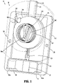
FIG. 1 is an illustration of an exemplary torsional insertion mechanism showing a frame assembly of the torsional insertion mechanism removed, in accordance with aspects of the disclosure; -
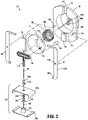
FIG. 2 is an exploded perspective view of the torsional insertion mechanism ofFIG. 1 showing a housing of the torsional insertion mechanism removed, in accordance with aspects of the disclosure; -
FIG. 3 is a cross-sectional view of the torsional insertion mechanism ofFIG. 1 illustrating components of the torsional insertion mechanism and showing a piston assembly of the insertion assembly in a first position, in accordance with aspects of the disclosure; -
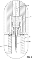
FIG. 4 is a cross-sectional view of the torsional insertion mechanism ofFIG. 1 illustrating a cannula carrier of the torsional insertion mechanism, in accordance with aspects of the disclosure; -
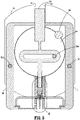
FIG. 5 is a cross-sectional view of the torsional insertion mechanism ofFIG. 1 illustrating components of the torsional insertion mechanism and showing the piston assembly of the insertion assembly in a first position, in accordance with aspects of the disclosure; -
FIGS. 6A and 6B are progressive side cutaway views of the torsional insertion mechanism ofFIG. 1 showing a stop member being removed, in accordance with aspects of the disclosure; -
FIGS. 7A and 7B are progressive side cutaway views of the torsional insertion mechanism ofFIG. 1 showing a rotatable assembly rotating from a first position to a second position, in accordance with aspects of the disclosure; -
FIGS. 8A and 8B are progressive side cutaway views of the torsional insertion mechanism ofFIG. 1 showing a rotatable assembly rotating from the second position to a third position, in accordance with aspects of the disclosure; and -
FIGS. 9A-9C are progressive side cutaway views of the torsional insertion mechanism ofFIG. 1 showing a latch assembly moving from a first latch position to a third latch position, in accordance with aspects of the disclosure. - This disclosure relates generally to insertion devices, and more particularly, to torsional insertion mechanisms for insulin infusion systems.
- Although the disclosure may be described primarily with respect to cannula insertion for insulin infusion systems, the scope of the disclosure is equally applicable other devices which include cannula, needles, or the like, that are at least partially implantable.
- As used herein, "exemplary" does not necessarily mean "preferred" and may simply refer to an example unless the context clearly indicates otherwise.
- Referring to
FIGS. 1-3 , an exemplary detachabletorsional insertion mechanism 100, of an exemplaryinfusion pump system 10, configured for cannula insertion is shown. Theinfusion pump system 10 generally includes a detachabletorsional insertion mechanism 100 and a disposablepatch pump assembly 130. The disposablepatch pump assembly 130 includes amedical reservoir 136 which if formed from anupper housing 136a and alower housing 136b (FIG. 2 ). Themedical reservoir 136 may include areservoir outlet 134. - The
torsional insertion mechanism 100 generally includes atorsion spring 106, arotatable assembly 104, aframe assembly 140, and apiston mechanism 110 configured to pierce tissue using acaptive introducer needle 122 and insert a cannula 124 (FIG. 4 ) into subcutaneous tissue. - The
torsion spring 106 is fixedly attached torotatable assembly 104. Thetorsion spring 106 is configured to rotate therotatable assembly 104 between a first position and a spring position. Thetorsion spring 106 includes aproximal portion 106a and adistal portion 106b. Theproximal portion 106a of thetorsion spring 106 may be retained in arecess 104d at thefirst surface 104c of therotatable assembly 104. Thedistal portion 106b of thetorsion spring 106 may be retained in a recess 144d at thetop surface 144c of theframe assembly 140. - The
torsion spring 106 is configured to store potential energy in a first position and then impart rotational motion to therotatable assembly 104. Thetorsion spring 106 may be pre-loaded (e.g., placed under tension) prior to installation in theinfusion pump system 10 such that thetorsion spring 106 stores potential energy for later use. - In aspects, the
torsional insertion mechanism 100 may further include astop member 108 configured to selectively prevent rotation of therotatable assembly 104. Thestop member 108 may be configured to move from a first stop position to prevent rotation of therotatable assembly 104 by engaging thestop recess 133 of therotatable assembly 104 to a second stop position to enable rotation of therotatable assembly 104 by disengaging thestop recess 133 of therotatable assembly 104. Thestop member 108 may be used to prevent rotation of therotatable assembly 104 untilcannula 124 insertion is desired. It is contemplated that any of a variety of triggering techniques may be used to move thestop member 108 out of the way and allow thetorsion spring 106 to impart rotational motion to therotatable assembly 104. Thestop member 108 is shown as cylindrical in shape, however, it is contemplated that thestop member 108 may be any suitable shape. - The
rotatable assembly 104 is configured to rotate in response to the torsional energy of thetorsional spring 106, and impart linear motion to thepiston mechanism 110 in response to the rotation of therotatable assembly 104. Therotatable assembly 104 includes arecess 104d on afirst surface 104c. Therecess 104d is configured for retaining theproximal portion 106a of thetorsional spring 106. Therotatable assembly 104 may include astop recess 104b that is configured to receive a stop member 108 (FIG. 1 ) for enabling or disabling rotation of therotatable assembly 104. - The
frame assembly 140, generally includes alatch assembly 102, aframe boss 146 configured for enabling thelatch assembly 102 to pivot about an axis, arecess 144c configured for receiving thetorsional spring 106 and therotatable assembly 104, therecess 144c configured for retaining thedistal portion 106b of thetorsion spring 106, and aguide boss 147 configured to guide the motion of adistal portion 115 of thepiston mechanism 110. - The
latch assembly 102 generally includes one ormore arms 102b and afinger 102a at a distal portion of each of thearms 102b. Eacharm 102b includes a through bore 102c configured to receive aframe boss 146 and selectively pivot about thatframe boss 146. Eachfinger 102a is configured to retain a disposablepatch pump assembly 130 of the exemplaryinfusion pump system 10. Thelatch assembly 102 may be actuated manually or by a motor (not shown). - The
guide boss 147 includes a throughbore 148 configured to guide the linear motion of thedistal portion 115 of thepiston mechanism 110. - The
piston mechanism 110 is configured to pierce tissue using acaptive introducer needle 122 and insert a cannula 124 (FIG. 4 ) into subcutaneous tissue in response to the rotational motion of therotatable assembly 104. Thepiston mechanism 110 generally includes aproximal portion 111, acenter portion 114, and adistal portion 115. Theproximal portion 111 is received by therecess 142 of theframe assembly 140. Theproximal portion 111 is configured to be guided by therecess 142 during linear motion of theproximal portion 111. Thecenter portion 114 of thepiston mechanism 110 includes aslot 112 configured for receivingboss 104e of therotatable assembly 104. As therotatable assembly 104 rotates, a linear motion is imparted on thepiston mechanism 110 in response to the motion of theboss 104e in theslot 112 ofpiston mechanism 110. - Referring to
FIG. 4 , a cross-sectional view of thedistal portion 115 of thepiston mechanism 110 is shown. Thedistal portion 115 of thepiston mechanism 110 is configured to move from a first insertion position (FIG. 7A ) to a second insertion position (FIG. 7B ) in response to the rotation of therotatable assembly 104. Thedistal portion 115 of thepiston mechanism 110 generally includes thecaptive introducer needle 122, aneedle guide 120a, and acannula carrier 120. The first insertion position of thedistal portion 115 of thepiston mechanism 110 may be a proximal position, and the second insertion position ofdistal portion 115 may be a distal position. Thedistal portion 115 of thepiston mechanism 110 may further move from the second insertion position (FIG. 8A ) to a third insertion position (FIG. 8B ) in response to further rotation of therotatable assembly 104. - The
captive introducer needle 122 projects outwardly and axially from the bottom of thedistal portion 115 of thepiston mechanism 110 and is configured to pierce the skin of a user and to enable thecannula 124 to penetrate or extend through the skin of the user. - The
needle guide 120a ofdistal portion 115 of thepiston mechanism 110 generally includes one or moreradial seals needle guide 120a and acaptive elastomer septum 120b that seals around theintroducer needle 122. In the figures, the one or moreradial seals distal portion 115 of thepiston mechanism 110. - The
cannula carrier 120 of thedistal portion 115 generally includes acannula 124 configured for fluid communication with a medical reservoir of a disposablepatch pump assembly 130, the medical reservoir being configured for holding a fluid medicament (e.g., insulin), one or moreradial seals cannula carrier 120 configured for sealing thecannula carrier 120, and a throughbore 132 configured for permitting the cannula andcaptive introducer needle 122 to pass through the throughbore 132 and into tissue. In aspects, thecannula carrier 120 may be secured to theneedle guide 120a through a press-fit engagement with thecannula 124, via glue, snaps, welding, and/or other suitable method of attachment. A fluid flow path 134 (FIG. 3 ) may be defined which passes through theneedle guide 120a and to thecannula 124 in thecannula carrier 120. Thecannula 124 may be captured in a radial gap defined between thecannula carrier 120 of theneedle guide 120a. - The
distal portion 115 of thepiston mechanism 110 is configured to move up and/or down or translate axially relative to a longitudinal axis defined by thecannula 124 orcannula carrier 120. In operation, during insertion of thecannula 124 into the tissue or through the skin of the user, thedistal portion 115 of thepiston mechanism 110 may push downward (e.g., in a direction toward the skin of the patient) or act on theneedle guide 120a, which may push down or act on thecannula carrier 120. In operation, thedistal portion 115 of thepiston mechanism 110 may also pull up (e.g., in a direction away from the skin of the user), to a third introducer position, to at least partially retract thecaptive introducer needle 122 through theneedle guide 120a. -
FIGS. 6A-8B show progressive views of the operation of thetorsional insertion mechanism 100 ofFIG. 1 . Initially, thestop member 108 is disengaged from therotatable assembly 104 of the torsional insertion mechanism 100 (FIGS. 6A and 6B ). For example, a motor (not shown) of an infusion pump system 10 (FIG. 1 ) may be used to remove thestop member 108. In another example, a push/pull button (not shown) may be used to disengage thestop member 108. Once thestop member 108 is removed, therotatable assembly 104 is no longer constrained against rotation and begins to rotate in response to the stored potential energy in thetorsional spring 106 being converted to kinetic energy. The pre-loaded (e.g., pre-tensioned and/or torsioned or wound)torsion spring 106 starts to impart torque and/or rotation on the rotatable assembly 104 (FIG. 11). Next, therotatable assembly 104 rotates in response to torque forces being imparted thereto by the torsional spring 106 (FIGS. 7A and 7B ), and moved from a first position to a second position. - As the
rotatable assembly 104 rotates, thedistal portion 115 of thepiston mechanism 110 is moved in a vertical motion (e.g., downward in an insertion direction toward the skin of the patent) in response to the rotation of therotatable assembly 104. - The
center portion 114 of thepiston mechanism 110 includes aslot 112 configured for receivingboss 104e of therotatable assembly 104. As therotatable assembly 104 rotates, a linear motion is imparted on thepiston mechanism 110 in response to the motion of theboss 104e in theslot 112. - The
boss 104e of therotatable assembly 104 moves alongslot 112 of thecenter portion 114 of thepiston mechanism 110 and imparts linear motion to thepiston mechanism 110, causing thedistal portion 115 of thepiston mechanism 110 to move in the downward direction from a first insertion position (FIG. 7A ) to a second insertion position (FIG. 7B ), exposing thecaptive introducer needle 122 andcannula 124 from the bottom of the disposablepatch pump assembly 130. - Referring to
FIG. 8B , afluid delivery path 802 of thetorsional insertion mechanism 100 is shown. In the second insertion position, afluid delivery path 134 is formed. Themedical reservoir 136 is configured to prevent medicament from flowing through thereservoir outlet 134 when thecannula 124 is in the first cannula position and to permit medicament flow through thereservoir outlet 134 in response to thecannula 124 being moved from the first cannula position. - Referring to
FIGS. 8A and 8B , as therotatable assembly 104 rotates from a second position (FIG. 8A ) to a third position (FIG. 8B ) in response to the rotational motion imparted by thetorsion spring 106, thecaptive introducer needle 122 retracts back into thedistal portion 115 of thepiston mechanism 110. Since theintroducer needle 122 is retracted, fluid delivery of the medicament (e.g., insulin) is enabled (FIG. 8B ). - Referring to
FIGS 9A-C progressive views of the actuation of thelatch assembly 102 of thetorsional insertion mechanism 100 ofFIG. 1 is shown. Initially, the latch assembly is in a first position, where it retains the disposablepatch pump assembly 130 of the exemplary infusion pump system 10 (FIG. 9A ). Next, thearms 102b of thelatch assembly 102 begin to pivot about frame boss 146 (FIG. 2 ) into a second position (FIG. 9B ), enabling eachfinger 102a which is at the distal portion of each of thearms 102b to release the disposablepatch pump assembly 130. Finally, the disposablepatch pump assembly 130 is released. - The phrases "in an embodiment," "in embodiments," "in various embodiments," "in some embodiments," or "in other embodiments" may each refer to one or more of the same or different embodiments in accordance with the disclosure. A phrase in the form "A or B" means "(A), (B), or (A and B)." A phrase in the form "at least one of A, B, or C" means "(A); (B); (C); (A and B); (A and C); (B and C); or (A, B, and C)."
- It should be understood that the foregoing description is only illustrative of the disclosure. To the extent consistent, any or all of the aspects detailed herein may be used in conjunction with any or all of the other aspects detailed herein. Various alternatives and modifications can be devised by those skilled in the art without departing from the disclosure. Accordingly, the disclosure is intended to embrace all such alternatives, modifications, and variances. The embodiments described with reference to the attached drawing figures are presented only to demonstrate certain examples of the disclosure. Other elements, steps, methods, and techniques that are insubstantially different from those described above and/or in the appended claims are also intended to be within the scope of the disclosure. Therefore, the above description should not be construed as limiting, but merely as exemplifications of particular embodiments. Those skilled in the art will envision other modifications within the scope and spirit of the claims appended hereto.
Claims (15)
- A detachable insertion mechanism (100), comprising:a torsion spring (106) configured to impart rotational motion to a rotatable assembly (104) and rotate the rotatable assembly (104) between a first position and a second position in response to the rotational motion; anda piston mechanism (110) connected to a distal portion (106b) of the torsion spring (106) and configured to move from a first insertion position to a second insertion position in response to the motion of the rotatable assembly (104), the piston mechanism (110) includes a captive introducer needle (122) disposed thereon, the captive introducer needle (122) configured to pierce tissue.
- The detachable insertion mechanism (100) according to claim 1, wherein the piston mechanism (110) is configured to move from the second insertion position to the first insertion position in response to the rotatable assembly (104) rotating from the second position to a third position respectively.
- The detachable insertion mechanism (100) according to claim 1 or 2, wherein the first insertion position is a proximal position and wherein the second insertion position is a distal position.
- The detachable insertion mechanism (100) according to any of claims 1 to 3, wherein the rotatable assembly (104) includes:a first surface (104c) defining a recess (104d); anda boss (104e) configured to impart a linear motion to the piston mechanism (110),wherein the piston mechanism (110) includes a mid-section (114) including an interior surface defining a slot (112), the slot configured to receive the boss (104e) and impart the linear motion to the piston mechanism (110).
- The detachable insertion mechanism (100) according to claim 4, wherein the piston mechanism (110) includes a cannula carrier (120) including a cannula (124) configured to be inserted into subcutaneous tissue; and
optionally the cannula (124) is moveable between a first cannula position and second cannula position in response to the rotation of the rotatable assembly (104). - The detachable insertion mechanism (100) according to any of claims 1 to 5, further comprising a latch assembly (102) configured to selectively attach the detachable insertion mechanism (100) to a disposable patch pump assembly (130); and
optionally the latch assembly (102) includes one or more latch arms (102b) including fingers (102a) on a distal portion of each of the latch arms (102b), wherein the fingers (102a) are configured to selectively hold and release the disposable patch pump assembly (130). - An infusion pump system (10), comprising:a detachable insertion mechanism (100) including:
a torsion spring (106) configured to impart rotational motion to a rotatable assembly (104) and rotate the rotatable assembly between a first position and a second position in response to the rotational motion; anda piston mechanism (110) connected to a distal portion (106b) of the torsion spring (106) and configured to move from a first insertion position to a second insertion position in response to the motion of the rotatable assembly (104), the piston mechanism (110) includes a captive introducer needle (122) disposed thereon, the captive introducer needle (122) configured to pierce tissue; anda disposable patch pump assembly (130) configured to dispense a medicament. - The infusion pump system (10) according to claim 7, wherein the piston mechanism (110) is configured to move from the second insertion position to the first insertion position in response to the rotatable assembly (104) rotating from the second position to a third position.
- The infusion pump system (10) according to claim 7 or 8, wherein the disposable patch pump assembly (130) includes:a housing including a through bore (132) configured for insertion of the captive introducer needle (122) into subcutaneous tissue; anda medical reservoir (136) configured for holding the medicament.
- The infusion pump system (10) according to claim 9, wherein the detachable insertion mechanism (100) further includes a cannula carrier (120) including a cannula (124) configured to be inserted into subcutaneous tissue wherein the cannula is moveable between a first cannula position and second cannula position in response to the rotation of the rotatable assembly (104); and
optionally the medical reservoir (136) includes a reservoir outlet (134) wherein the medical reservoir (136) is configured to prevent medicament from flowing through the reservoir outlet (134) when the cannula is in the first cannula position and to permit medicament to flow through the reservoir outlet (134) in response to the cannula (124) being moved from the first cannula position. - The infusion pump system (10) according to any of claims 7 to 10, wherein the detachable insertion mechanism (100) further includes a latch member (102) configured to selectively attach the detachable insertion mechanism (100) to the disposable patch pump assembly (130).
- The infusion pump system (10) according to any of claims 7 to 11, wherein the torsion spring (106) is configured to rotate the rotatable assembly (104) between a first spring position and a second spring position; and
optionally the piston mechanism (110) is configured to move from a first insertion position to a second insertion position in response to the rotation of the rotatable assembly (104). - The infusion pump system (10) according to any of claims 7 to 12, wherein the rotatable assembly (104) includes a side surface defining a recess (104b),wherein the detachable insertion mechanism further includes a stop member (108) configured to selectively prevent rotation of the rotatable assembly, andwherein the rotatable assembly (104) is configured to receive the stop member (108) in the recess (104b).
- The infusion pump system (10) according to any of claims 7 to 13, wherein the first insertion position is a proximal position and wherein the second insertion position is a distal position.
- A method for operating an infusion pump system (10), the method comprising:inserting a cannula carrier (120) of a detachable insertion mechanism (100) into a disposable patch pump (130) assembly in response to rotational motion of a rotatable assembly (104) of the detachable insertion mechanism (100), wherein the rotatable assembly (104) rotates in response to motion imparted by a torsional spring (106);forming an environmental and a fluid path seal (120c, 120d) in response to the cannula carrier (120) being inserted into the patch pump assembly;inserting the cannula (124) into subcutaneous tissue in response to the rotation motion of the rotatable assembly (104); andretracting an introducer needle (122) in response to the rotation motion of the rotatable assembly (104).
Applications Claiming Priority (2)
| Application Number | Priority Date | Filing Date | Title |
|---|---|---|---|
| US202063112582P | 2020-11-11 | 2020-11-11 | |
| US17/496,038 US12447269B2 (en) | 2020-11-11 | 2021-10-07 | Torsional insertion devices |
Publications (1)
| Publication Number | Publication Date |
|---|---|
| EP4000667A1 true EP4000667A1 (en) | 2022-05-25 |
Family
ID=78592696
Family Applications (1)
| Application Number | Title | Priority Date | Filing Date |
|---|---|---|---|
| EP21207345.6A Pending EP4000667A1 (en) | 2020-11-11 | 2021-11-10 | Torsional insertion devices |
Country Status (3)
| Country | Link |
|---|---|
| US (2) | US12447269B2 (en) |
| EP (1) | EP4000667A1 (en) |
| CN (1) | CN114534011A (en) |
Families Citing this family (1)
| Publication number | Priority date | Publication date | Assignee | Title |
|---|---|---|---|---|
| US11951281B2 (en) | 2020-11-11 | 2024-04-09 | Medtronic Minimed, Inc. | Fluid conduit insertion devices |
Citations (3)
| Publication number | Priority date | Publication date | Assignee | Title |
|---|---|---|---|---|
| US20080051718A1 (en) * | 2006-08-23 | 2008-02-28 | Medtronic Minimed, Inc. | Infusion medium delivery system, device and method with needle inserter and needle inserter device and method |
| US20100217105A1 (en) * | 2006-11-28 | 2010-08-26 | Ofer Yodfat | Insertion device and method for inserting a subcutaneously insertable element into body |
| US20190117885A1 (en) * | 2014-04-24 | 2019-04-25 | Becton, Dickinson And Company | Cannula deployment mechanism |
Family Cites Families (97)
| Publication number | Priority date | Publication date | Assignee | Title |
|---|---|---|---|---|
| US5338157B1 (en) | 1992-09-09 | 1999-11-02 | Sims Deltec Inc | Systems and methods for communicating with ambulat |
| US4755173A (en) | 1986-02-25 | 1988-07-05 | Pacesetter Infusion, Ltd. | Soft cannula subcutaneous injection set |
| US5307263A (en) | 1992-11-17 | 1994-04-26 | Raya Systems, Inc. | Modular microprocessor-based health monitoring system |
| US5956501A (en) | 1997-01-10 | 1999-09-21 | Health Hero Network, Inc. | Disease simulation system and method |
| US5832448A (en) | 1996-10-16 | 1998-11-03 | Health Hero Network | Multiple patient monitoring system for proactive health management |
| US5545143A (en) | 1993-01-21 | 1996-08-13 | T. S. I. Medical | Device for subcutaneous medication delivery |
| DK25793A (en) | 1993-03-09 | 1994-09-10 | Pharma Plast Int As | Infusion set for intermittent or continuous administration of a therapeutic agent |
| US5536249A (en) | 1994-03-09 | 1996-07-16 | Visionary Medical Products, Inc. | Pen-type injector with a microprocessor and blood characteristic monitor |
| US5391250A (en) | 1994-03-15 | 1995-02-21 | Minimed Inc. | Method of fabricating thin film sensors |
| IE72524B1 (en) | 1994-11-04 | 1997-04-23 | Elan Med Tech | Analyte-controlled liquid delivery device and analyte monitor |
| US5665065A (en) | 1995-05-26 | 1997-09-09 | Minimed Inc. | Medication infusion device with blood glucose data input |
| ATE278801T1 (en) | 1995-11-22 | 2004-10-15 | Medtronic Minimed Inc | DETECTION OF BIOLOGICAL MOLECULES USING CHEMICAL AMPLIFICATION AND OPTICAL SENSOR |
| US6766183B2 (en) | 1995-11-22 | 2004-07-20 | Medtronic Minimed, Inc. | Long wave fluorophore sensor compounds and other fluorescent sensor compounds in polymers |
| US6607509B2 (en) | 1997-12-31 | 2003-08-19 | Medtronic Minimed, Inc. | Insertion device for an insertion set and method of using the same |
| DE19717107B4 (en) | 1997-04-23 | 2005-06-23 | Disetronic Licensing Ag | System of container and drive device for a piston, which is held in the container containing a drug fluid |
| US6186982B1 (en) | 1998-05-05 | 2001-02-13 | Elan Corporation, Plc | Subcutaneous drug delivery device with improved filling system |
| US6558351B1 (en) | 1999-06-03 | 2003-05-06 | Medtronic Minimed, Inc. | Closed loop system for controlling insulin infusion |
| US5954643A (en) | 1997-06-09 | 1999-09-21 | Minimid Inc. | Insertion set for a transcutaneous sensor |
| US7647237B2 (en) | 1998-04-29 | 2010-01-12 | Minimed, Inc. | Communication station and software for interfacing with an infusion pump, analyte monitor, analyte meter, or the like |
| US6175752B1 (en) | 1998-04-30 | 2001-01-16 | Therasense, Inc. | Analyte monitoring device and methods of use |
| US6736797B1 (en) | 1998-06-19 | 2004-05-18 | Unomedical A/S | Subcutaneous infusion set |
| US6355021B1 (en) | 1998-07-14 | 2002-03-12 | Maersk Medical A/S | Medical puncturing device |
| US6558320B1 (en) | 2000-01-20 | 2003-05-06 | Medtronic Minimed, Inc. | Handheld personal data assistant (PDA) with a medical device and method of using the same |
| US6248067B1 (en) | 1999-02-05 | 2001-06-19 | Minimed Inc. | Analyte sensor and holter-type monitor system and method of using the same |
| US6554798B1 (en) | 1998-08-18 | 2003-04-29 | Medtronic Minimed, Inc. | External infusion device with remote programming, bolus estimator and/or vibration alarm capabilities |
| CA2666429A1 (en) | 1998-10-08 | 2000-04-13 | Medtronic Minimed, Inc. | Telemetered characteristic monitor system |
| US7193521B2 (en) | 1998-10-29 | 2007-03-20 | Medtronic Minimed, Inc. | Method and apparatus for detecting errors, fluid pressure, and occlusions in an ambulatory infusion pump |
| WO2000025844A1 (en) | 1998-10-29 | 2000-05-11 | Minimed Inc. | Compact pump drive system |
| US6248093B1 (en) | 1998-10-29 | 2001-06-19 | Minimed Inc. | Compact pump drive system |
| US7806886B2 (en) | 1999-06-03 | 2010-10-05 | Medtronic Minimed, Inc. | Apparatus and method for controlling insulin infusion with state variable feedback |
| US6453956B2 (en) | 1999-11-05 | 2002-09-24 | Medtronic Minimed, Inc. | Needle safe transfer guard |
| US7003336B2 (en) | 2000-02-10 | 2006-02-21 | Medtronic Minimed, Inc. | Analyte sensor method of making the same |
| US6895263B2 (en) | 2000-02-23 | 2005-05-17 | Medtronic Minimed, Inc. | Real time self-adjusting calibration algorithm |
| US7890295B2 (en) | 2000-02-23 | 2011-02-15 | Medtronic Minimed, Inc. | Real time self-adjusting calibration algorithm |
| US20010041869A1 (en) | 2000-03-23 | 2001-11-15 | Causey James D. | Control tabs for infusion devices and methods of using the same |
| US7530964B2 (en) | 2000-06-30 | 2009-05-12 | Elan Pharma International Limited | Needle device and method thereof |
| US6740059B2 (en) | 2000-09-08 | 2004-05-25 | Insulet Corporation | Devices, systems and methods for patient infusion |
| EP1702635B1 (en) * | 2000-11-09 | 2008-01-16 | Insulet Corporation | Transcutaneous delivery means |
| US6749587B2 (en) | 2001-02-22 | 2004-06-15 | Insulet Corporation | Modular infusion device and method |
| WO2002081012A2 (en) | 2001-04-06 | 2002-10-17 | Disetronic Licensing Ag | Infusion set |
| US20020071225A1 (en) | 2001-04-19 | 2002-06-13 | Minimed Inc. | Direct current motor safety circuits for fluid delivery systems |
| US6544212B2 (en) | 2001-07-31 | 2003-04-08 | Roche Diagnostics Corporation | Diabetes management system |
| US7399277B2 (en) | 2001-12-27 | 2008-07-15 | Medtronic Minimed, Inc. | System for monitoring physiological characteristics |
| US8010174B2 (en) | 2003-08-22 | 2011-08-30 | Dexcom, Inc. | Systems and methods for replacing signal artifacts in a glucose sensor data stream |
| US7041082B2 (en) | 2002-02-28 | 2006-05-09 | Smiths Medical Md, Inc. | Syringe pump control systems and methods |
| US6960192B1 (en) | 2002-04-23 | 2005-11-01 | Insulet Corporation | Transcutaneous fluid delivery system |
| US20040010207A1 (en) * | 2002-07-15 | 2004-01-15 | Flaherty J. Christopher | Self-contained, automatic transcutaneous physiologic sensing system |
| US20040068230A1 (en) | 2002-07-24 | 2004-04-08 | Medtronic Minimed, Inc. | System for providing blood glucose measurements to an infusion device |
| US7278983B2 (en) | 2002-07-24 | 2007-10-09 | Medtronic Minimed, Inc. | Physiological monitoring device for controlling a medication infusion device |
| US7488601B2 (en) | 2003-06-20 | 2009-02-10 | Roche Diagnostic Operations, Inc. | System and method for determining an abused sensor during analyte measurement |
| US8282549B2 (en) | 2003-12-09 | 2012-10-09 | Dexcom, Inc. | Signal processing for continuous analyte sensor |
| US8275437B2 (en) | 2003-08-01 | 2012-09-25 | Dexcom, Inc. | Transcutaneous analyte sensor |
| US7699807B2 (en) | 2003-11-10 | 2010-04-20 | Smiths Medical Asd, Inc. | Device and method for insertion of a cannula of an infusion device |
| GB0329161D0 (en) | 2003-12-16 | 2004-01-21 | Precisense As | Reagant for detecting an analyte |
| GB0329849D0 (en) | 2003-12-23 | 2004-01-28 | Precisense As | Fluorometers |
| US7344500B2 (en) | 2004-07-27 | 2008-03-18 | Medtronic Minimed, Inc. | Sensing system with auxiliary display |
| US8313433B2 (en) | 2004-08-06 | 2012-11-20 | Medtronic Minimed, Inc. | Medical data management system and process |
| US7468033B2 (en) | 2004-09-08 | 2008-12-23 | Medtronic Minimed, Inc. | Blood contacting sensor |
| CN101180093B (en) | 2005-03-21 | 2012-07-18 | 雅培糖尿病护理公司 | Method and system for providing integrated medication infusion and analyte monitoring system |
| EP1877116A1 (en) | 2005-04-13 | 2008-01-16 | Novo Nordisk A/S | Medical skin mountable device and system |
| US8277415B2 (en) | 2006-08-23 | 2012-10-02 | Medtronic Minimed, Inc. | Infusion medium delivery device and method with drive device for driving plunger in reservoir |
| US20080097291A1 (en) | 2006-08-23 | 2008-04-24 | Hanson Ian B | Infusion pumps and methods and delivery devices and methods with same |
| US9233203B2 (en) | 2005-05-06 | 2016-01-12 | Medtronic Minimed, Inc. | Medical needles for damping motion |
| US8137314B2 (en) | 2006-08-23 | 2012-03-20 | Medtronic Minimed, Inc. | Infusion medium delivery device and method with compressible or curved reservoir or conduit |
| US7713240B2 (en) | 2005-09-13 | 2010-05-11 | Medtronic Minimed, Inc. | Modular external infusion device |
| DE602006008494D1 (en) | 2005-11-08 | 2009-09-24 | M2 Medical As | INFUSION PUMP SYSTEM |
| US8114268B2 (en) | 2005-12-30 | 2012-02-14 | Medtronic Minimed, Inc. | Method and system for remedying sensor malfunctions detected by electrochemical impedance spectroscopy |
| US7985330B2 (en) | 2005-12-30 | 2011-07-26 | Medtronic Minimed, Inc. | Method and system for detecting age, hydration, and functional states of sensors using electrochemical impedance spectroscopy |
| US8114269B2 (en) | 2005-12-30 | 2012-02-14 | Medtronic Minimed, Inc. | System and method for determining the point of hydration and proper time to apply potential to a glucose sensor |
| US20070255125A1 (en) | 2006-04-28 | 2007-11-01 | Moberg Sheldon B | Monitor devices for networked fluid infusion systems |
| US7828764B2 (en) | 2006-08-23 | 2010-11-09 | Medtronic Minimed, Inc. | Systems and methods allowing for reservoir filling and infusion medium delivery |
| US20080125700A1 (en) | 2006-11-29 | 2008-05-29 | Moberg Sheldon B | Methods and apparatuses for detecting medical device acceleration, temperature, and humidity conditions |
| US7946985B2 (en) | 2006-12-29 | 2011-05-24 | Medtronic Minimed, Inc. | Method and system for providing sensor redundancy |
| US20080269714A1 (en) | 2007-04-25 | 2008-10-30 | Medtronic Minimed, Inc. | Closed loop/semi-closed loop therapy modification system |
| US7963954B2 (en) | 2007-04-30 | 2011-06-21 | Medtronic Minimed, Inc. | Automated filling systems and methods |
| US8323250B2 (en) | 2007-04-30 | 2012-12-04 | Medtronic Minimed, Inc. | Adhesive patch systems and methods |
| WO2008133702A1 (en) | 2007-04-30 | 2008-11-06 | Medtronic Minimed, Inc. | Needle inserting and fluid flow connection for infusion medium delivery system |
| US8002752B2 (en) | 2007-06-25 | 2011-08-23 | Medingo, Ltd. | Protector apparatus |
| CN101801438B (en) | 2007-07-20 | 2013-08-07 | 梅丁格有限公司 | Manually operable portable infusion device |
| DE102007049446A1 (en) | 2007-10-16 | 2009-04-23 | Cequr Aps | Catheter introducer |
| US8207859B2 (en) | 2008-04-28 | 2012-06-26 | Medtronic Minimed, Inc. | Automobile physiological monitoring system and method for using the same |
| US8181849B2 (en) | 2008-12-30 | 2012-05-22 | Medtronic Minimed, Inc. | Color detection system for detecting reservoir presence and content in device |
| US8308679B2 (en) | 2009-12-30 | 2012-11-13 | Medtronic Minimed, Inc. | Alignment systems and methods |
| ES2732080T3 (en) | 2011-02-09 | 2019-11-20 | Becton Dickinson Co | Subcutaneous infusion device |
| RS65875B1 (en) | 2012-03-30 | 2024-09-30 | Insulet Corp | Fluid delivery device with transcutaneous access tool, insertion mechanism and blood glucose monitoring for use therewith |
| US9375537B2 (en) | 2013-10-14 | 2016-06-28 | Medtronic Minimed, Inc. | Therapeutic agent injection device |
| WO2016007935A2 (en) | 2014-07-10 | 2016-01-14 | Companion Medical, Inc. | Medicine administering system including injection pen and companion device |
| EP3848072A1 (en) * | 2014-12-19 | 2021-07-14 | Amgen Inc. | Drug delivery device with proximity sensor |
| CA3033266A1 (en) * | 2016-09-15 | 2018-03-22 | Becton, Dickinson And Company | Needle hub for subcutaneous infusion set |
| EP3354303B1 (en) | 2017-01-31 | 2020-01-08 | Société Industrielle de Sonceboz S.A. | Drug delivery system |
| AU2018230486B2 (en) | 2017-03-09 | 2023-05-11 | Amgen Inc. | Insertion mechanism for drug delivery device |
| US11260171B2 (en) | 2017-07-04 | 2022-03-01 | Medtronic Minimed, Inc. | Ambulatory infusion pumps and assemblies for use with same |
| US11083840B2 (en) | 2018-06-01 | 2021-08-10 | Amgen Inc. | Modular fluid path assemblies for drug delivery devices |
| EP3632487B1 (en) | 2018-10-05 | 2024-06-12 | LTS Device Technologies Ltd | Triggering sequence |
| US11948671B2 (en) | 2019-04-11 | 2024-04-02 | Medtronic Minimed, Inc. | Intelligent accessories for medicine dispensing device |
| US20220143306A1 (en) | 2020-11-11 | 2022-05-12 | Medtronic Minimed, Inc. | Torsional insertion devices |
| US11951281B2 (en) | 2020-11-11 | 2024-04-09 | Medtronic Minimed, Inc. | Fluid conduit insertion devices |
-
2021
- 2021-10-07 US US17/496,038 patent/US12447269B2/en active Active
- 2021-11-05 CN CN202111305294.5A patent/CN114534011A/en active Pending
- 2021-11-10 EP EP21207345.6A patent/EP4000667A1/en active Pending
-
2025
- 2025-09-10 US US19/324,684 patent/US20260007820A1/en active Pending
Patent Citations (3)
| Publication number | Priority date | Publication date | Assignee | Title |
|---|---|---|---|---|
| US20080051718A1 (en) * | 2006-08-23 | 2008-02-28 | Medtronic Minimed, Inc. | Infusion medium delivery system, device and method with needle inserter and needle inserter device and method |
| US20100217105A1 (en) * | 2006-11-28 | 2010-08-26 | Ofer Yodfat | Insertion device and method for inserting a subcutaneously insertable element into body |
| US20190117885A1 (en) * | 2014-04-24 | 2019-04-25 | Becton, Dickinson And Company | Cannula deployment mechanism |
Also Published As
| Publication number | Publication date |
|---|---|
| CN114534011A (en) | 2022-05-27 |
| US12447269B2 (en) | 2025-10-21 |
| US20260007820A1 (en) | 2026-01-08 |
| US20220143302A1 (en) | 2022-05-12 |
Similar Documents
| Publication | Publication Date | Title |
|---|---|---|
| US20240148964A1 (en) | Subcutaneous infusion device | |
| EP3549524B1 (en) | Fluid delivery device with transcutaneous access tool, insertion mechanism and blood glucose monitoring for use therewith | |
| EP1646412B1 (en) | Portable drug delivery device having an encapsulated needle | |
| EP1631336B1 (en) | Pivotable injection needle unit | |
| CA2826096C (en) | Self-contained inserter for drug delivery infusion set | |
| US7981085B2 (en) | Internal needle inserter | |
| CN100584399C (en) | Medical device with percutaneous cannula device | |
| US20050043687A1 (en) | Injector device for placing a subcutaneous infusion set | |
| US20240325635A1 (en) | Systems for delivering fluid to a user transcutaneously | |
| US12465683B2 (en) | Fluid conduit insertion devices | |
| EP4000668A1 (en) | Insertion based on helical tracks | |
| US20260007820A1 (en) | Torsional insertion devices |
Legal Events
| Date | Code | Title | Description |
|---|---|---|---|
| PUAI | Public reference made under article 153(3) epc to a published international application that has entered the european phase |
Free format text: ORIGINAL CODE: 0009012 |
|
| STAA | Information on the status of an ep patent application or granted ep patent |
Free format text: STATUS: THE APPLICATION HAS BEEN PUBLISHED |
|
| AK | Designated contracting states |
Kind code of ref document: A1 Designated state(s): AL AT BE BG CH CY CZ DE DK EE ES FI FR GB GR HR HU IE IS IT LI LT LU LV MC MK MT NL NO PL PT RO RS SE SI SK SM TR |
|
| STAA | Information on the status of an ep patent application or granted ep patent |
Free format text: STATUS: REQUEST FOR EXAMINATION WAS MADE |
|
| 17P | Request for examination filed |
Effective date: 20221108 |
|
| RBV | Designated contracting states (corrected) |
Designated state(s): AL AT BE BG CH CY CZ DE DK EE ES FI FR GB GR HR HU IE IS IT LI LT LU LV MC MK MT NL NO PL PT RO RS SE SI SK SM TR |
|
| STAA | Information on the status of an ep patent application or granted ep patent |
Free format text: STATUS: EXAMINATION IS IN PROGRESS |
|
| 17Q | First examination report despatched |
Effective date: 20250528 |