EP1631336B1 - Pivotable injection needle unit - Google Patents
Pivotable injection needle unit Download PDFInfo
- Publication number
- EP1631336B1 EP1631336B1 EP04731881A EP04731881A EP1631336B1 EP 1631336 B1 EP1631336 B1 EP 1631336B1 EP 04731881 A EP04731881 A EP 04731881A EP 04731881 A EP04731881 A EP 04731881A EP 1631336 B1 EP1631336 B1 EP 1631336B1
- Authority
- EP
- European Patent Office
- Prior art keywords
- needle
- reservoir
- transcutaneous device
- transcutaneous
- housing
- Prior art date
- Legal status (The legal status is an assumption and is not a legal conclusion. Google has not performed a legal analysis and makes no representation as to the accuracy of the status listed.)
- Not-in-force
Links
Images


Classifications
-
- A—HUMAN NECESSITIES
- A61—MEDICAL OR VETERINARY SCIENCE; HYGIENE
- A61M—DEVICES FOR INTRODUCING MEDIA INTO, OR ONTO, THE BODY; DEVICES FOR TRANSDUCING BODY MEDIA OR FOR TAKING MEDIA FROM THE BODY; DEVICES FOR PRODUCING OR ENDING SLEEP OR STUPOR
- A61M5/00—Devices for bringing media into the body in a subcutaneous, intra-vascular or intramuscular way; Accessories therefor, e.g. filling or cleaning devices, arm-rests
- A61M5/14—Infusion devices, e.g. infusing by gravity; Blood infusion; Accessories therefor
- A61M5/158—Needles for infusions; Accessories therefor, e.g. for inserting infusion needles, or for holding them on the body
-
- A—HUMAN NECESSITIES
- A61—MEDICAL OR VETERINARY SCIENCE; HYGIENE
- A61B—DIAGNOSIS; SURGERY; IDENTIFICATION
- A61B5/00—Measuring for diagnostic purposes; Identification of persons
- A61B5/68—Arrangements of detecting, measuring or recording means, e.g. sensors, in relation to patient
- A61B5/6846—Arrangements of detecting, measuring or recording means, e.g. sensors, in relation to patient specially adapted to be brought in contact with an internal body part, i.e. invasive
- A61B5/6847—Arrangements of detecting, measuring or recording means, e.g. sensors, in relation to patient specially adapted to be brought in contact with an internal body part, i.e. invasive mounted on an invasive device
- A61B5/6848—Needles
- A61B5/6849—Needles in combination with a needle set
-
- A—HUMAN NECESSITIES
- A61—MEDICAL OR VETERINARY SCIENCE; HYGIENE
- A61M—DEVICES FOR INTRODUCING MEDIA INTO, OR ONTO, THE BODY; DEVICES FOR TRANSDUCING BODY MEDIA OR FOR TAKING MEDIA FROM THE BODY; DEVICES FOR PRODUCING OR ENDING SLEEP OR STUPOR
- A61M5/00—Devices for bringing media into the body in a subcutaneous, intra-vascular or intramuscular way; Accessories therefor, e.g. filling or cleaning devices, arm-rests
- A61M5/14—Infusion devices, e.g. infusing by gravity; Blood infusion; Accessories therefor
- A61M5/142—Pressure infusion, e.g. using pumps
- A61M5/14244—Pressure infusion, e.g. using pumps adapted to be carried by the patient, e.g. portable on the body
- A61M5/14248—Pressure infusion, e.g. using pumps adapted to be carried by the patient, e.g. portable on the body of the skin patch type
- A61M2005/14252—Pressure infusion, e.g. using pumps adapted to be carried by the patient, e.g. portable on the body of the skin patch type with needle insertion means
Definitions
- the present invention generally relates to the insertion of transcutaneous devices such as needles, needle-like members and cannulas. More specifically, the invention relates to insertion of a transcutaneous device at a selected site within the body of a subject for subcutaneous, intravenous, intramuscular or intradermal delivery of a drug to the subject, the transcutaneous device being carried by a device comprising a mounting surface adapted for application to the skin of the subject. Especially, the invention relates to insertion of an infusion needle or cannula for the infusion of a drug, to insertion of a needle-formed sensor, as well as to insertion of insertion needles for easy placement of a device such as a sensor through the skin of a subject.
- Portable drug delivery devices for delivering a drug to a patient are well known and generally comprise a reservoir adapted to contain a liquid drug and having an outlet in fluid communication with a hollow infusion needle, as well as expelling means for expelling a drug out of the reservoir and through the skin of the subject via the hollow needle.
- Such devices are often termed infusion pumps.
- infusion pumps can be divided into two classes.
- the first class comprises durable infusion pumps which are relatively expensive pumps intended for 3-4 years use, for which reason the initial cost for such a pump often is a barrier to this type of therapy.
- the pump offer the advantages of continuous infusion of insulin, precision in dosing and optionally programmable delivery profiles and user actuated bolus infusions in connections with meals.
- the disposable pumps generally comprises a skin-contacting mounting surface adapted for application to the skin of a subject by adhesive means, and with the infusion needle arranged such that in a situation of use it projects from the mounting surface to thereby penetrate the skin of the subject, whereby the place where the needle penetrates the skin is covered while the appliance is in use.
- the infusion needle may be arranged to permanently project from the mounting surface such that the needle is inserted simultaneously with the application of the infusion pump. Examples of this configuration can be found in US patents 2,605,765 , 4,340,048 and in EP 1 177 802 . Although this configuration provides a simple and cost-effective solution, the actual user-performed piercing of the tissue with the needle is often problematic as people who are not experts in medicine are usually insufficiently practised to place such a needle correctly and they often suffer from a fear of the likely pain.
- US patent 5,851,197 discloses an injector in which an infusion set comprising a skin-mountable surface with a protruding needle can be mounted, the injector upon actuation driving the entire infusion set into contact with a skin portion whereby the needle is inserted through the skin.
- infusion pump devices have been proposed in which the pump device is supplied to the user with the needle in a retracted state, i.e. with the distal pointed end of the needle "hidden” inside the pump device, this allowing the user to place the pump device on the skin without the possibility of observing the needle.
- the needle is hidden, at least some of the fear is overcome making the introduction of the needle in a second step less problematic.
- US patents 5,858,001 and 5,814,020 disclose infusion devices of this type in which an infusion needle is arranged in an upper housing portion pivotably arranged relative to a base plate portion. In this way the user can introduce the needle by pressing the upper portion into engagement with the base plate portion.
- US patent 5,957,895 discloses a liquid drug delivery device comprising a bent injection needle which is adapted to project through a needle aperture in the bottom surface of the housing in a situation of use.
- a movable needle carrier is disposed in the housing for carrying the injection needle and for causing the injection end of the needle to project through the needle aperture upon movement of the needle carrier.
- US patent 5,931,814 discloses an infusion device having a housing with a drug reservoir, an infusion needle (or cannula) communicating with the reservoir, means for inserting the needle, and pump means for discharging the reservoir contents through the needle.
- the needle is fixed relative to the housing and projects beyond the lower skin-contacting surface of the housing to the depth required for injection.
- the needle is surrounded by a protective element which is moved by spring means from a first end position in which the protective device projects beyond the lower surface of the housing and beyond the needle to a second end position in which the protective device does not project beyond the underside of the casing.
- WO 02/15965 discloses a similar infusion device in which a base plate member acts as a protecting element until an upper part of the device, to which the needle is fixed, is moved down into engagement with the base plate member.
- the needle is automatically inserted by the release of pre-tensioned spring means arranged within the devices, whereas in the device known from WO 02/15965 the needle is inserted by the user actively moving the hidden needle.
- the automatic needle insertion means adds convenience for the user and may serve to overcome needle fear, such means also adds to the complexity and thus to the cost of the device, they may reduce the reliability, just as they may add to the bulkiness of the device.
- the problem of inserting a needle-formed device through the skin of a subject also relates to other fields, e.g. the introduction of needle-formed sensors comprising sensor means capable of being influenced by a body substance and producing a signal corresponding thereto (e.g. blood glucose).
- sensor means capable of being influenced by a body substance and producing a signal corresponding thereto (e.g. blood glucose).
- an object of the present invention as claimed to provide an insertion means for a transcutaneous device mounted in a device and which allows for easy and swift insertion of the transcutaneous device, yet is reliable in use.
- the device should be compact in size and be designed for cost effective manufacturing.
- a medical device is provided as defined in claim 1, the two-part form being based upon US 5,858,001 .
- WO 2004/029457 has been cited with reference to Art. 54(3) EPC, the document disclosing a transcutaneous device unit containing a pump as well as pump actuating means.
- the transcutaneous device may e.g. be in the form of a pointed hollow infusion needle or a combination of a relatively flexible per se blunt cannula with a pointed insertion needle may provide a pointed transcutaneous device, the insertion needle being retractable after insertion of the blunt portion of the transcutaneous device.
- the cannula is advantageously soft and flexible relative to the insertion needle which typically is a solid steel needle.
- the transcutaneous device may also be a composite structure comprising a distal portion, a proximal portion and an intermediate portion provided by different types of conduits.
- a transcutaneous device unit may comprise a distal portion in the form of a cannula in combination with an insertion needle, a proximal portion in the form of a hollow infusion-type needle, and an intermediate portion connecting the distal and proximal portions and being formed in a carrier member in which the distal and proximal portions are mounted.
- the distal portion may also be in the form of a micro needle array.
- a distal end of a transcutaneous device can be moved between a retracted state and an extended state, yet providing a proximal end allowing a high degree of flexibility and reliability for connection to a fluid reservoir.
- a fluid reservoir may be (or may be brought) in fluid communication with proximal end of the transcutaneous device before the needle unit is pivoted, or the fluid reservoir may be brought in fluid communication with the proximal end of the transcutaneous device during or after the transcutaneous device unit is pivoting.
- the only requirement for allowing this arrangement would be that the fluid connection allows rotation of the proximal transcutaneous device end and is moved axially corresponding to the pivoting axis.
- a medical device further comprising a reservoir adapted to contain a liquid drug and comprising in a situation of use an outlet in fluid communication with the transcutaneous device, and expelling means for expelling a drug out of the reservoir and through the skin of the subject via the transcutaneous device.
- the reservoir advantageously comprises outlet means adapted to cooperate with the proximal portion of the transcutaneous device (thus serving as an inlet portion), the outlet means being arranged substantially corresponding to the pivoting axis, thereby allowing the transcutaneous device unit to pivot substantially without non-rotational displacement of the inlet portion of the transcutaneous device relative to the outlet means.
- the reservoir and the inlet portion may be arranged moveable relative to each other, corresponding substantially to the pivoting axis, between a disconnected position in which there is no fluid communication between the reservoir and the inlet portion, and a connected position in which fluid communication between the reservoir and the inlet portion is established.
- the inlet portion of the transcutaneous device comprises a pointed proximal end
- the outlet means of reservoir comprises a needle-penetratable septum, e.g. a self-sealing elastomeric septum.
- the transcutaneous device unit may be inserted manually, or the medical device may comprise actuatable driving means disposed within the housing and adapted to pivot the transcutaneous device unit from the first position to the second position.
- the driving means may be actuated by actuation means moveable, relative to the housing, from a first position to a second position thereby actuating the driving means.
- the reservoir is connected to the actuation means, whereby movement of the actuation means between the first and the second position causes the reservoir to be arranged in fluid communication with the transcutaneous device.
- the device comprises common actuation means moveable, relative to the housing, from a first position to a second position thereby actuating the driving means, wherein the reservoir is connected to the actuation means such that movement of the actuation means between the first and the second position causes the reservoir to be arranged in fluid communication with the transcutaneous device, the inlet portion of the transcutaneous device being introduced through the needle-penetratable septum either before or after the transcutaneous device unit is pivoted from the first position to the second position.
- the transcutaneous device unit may be in the form of a "naked" needle, however, in advantageous embodiments the transcutaneous device unit comprises a carrier for the transcutaneous device, the transcutaneous device being carried by (or formed integrally with) the carrier, the carrier being connected to the housing by the hinge.
- the hinge may be provided by cooperating members of the carrier respectively the housing, or the carrier and the housing may be formed integrally connected to each other by a film-hinge.
- the transcutaneous device carrier would serve only as a carrier, however, the carrier may be provided with a pump for pumping a liquid between the inlet and outlet portion of the transcutaneous device.
- the mounting surface advantageously comprises adhesive means for adhering the first unit to the skin of the subject.
- drug is meant to encompass any drug-containing flowable medicine capable of being passed through a delivery means such as a hollow needle in a controlled manner, such as a liquid, solution, gel or fine suspension.
- Representative drugs include pharmaceuticals such as peptides, proteins (e.g. insulin, insulin analogues and C-peptide), and hormones, biologically derived or active agents, hormonal and gene based agents, nutritional formulas and other substances in both solid (dispensed) or liquid form.
- peptides e.g. insulin, insulin analogues and C-peptide
- hormones e.g. insulin, insulin analogues and C-peptide
- hormones e.g. insulin, insulin analogues and C-peptide
- hormones e.g. insulin, insulin analogues and C-peptide
- hormones e.g. insulin, insulin analogues and C-peptide
- hormones e.g. insulin, insulin analogues and C-peptide
- hormones e.g. insulin
- FIGs. 1-3 show in schematic representations perspective views of different states of use of a medical device in accordance with the invention.
- the configuration of the different structures as well as there relative dimensions are intended to serve illustrative purposes only.
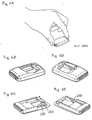
- fig. 1A shows a first embodiment of a medical device 100 gripped by a user.
- the medical device comprises a housing with an upper housing portion 110 and a lower base plate portion 120, the housing providing a cavity in which an actuation member 130 is slidingly received through an opening, the actuation element being moveable corresponding to a longitudinal direction in respect of the device.
- the base plate portion comprises an adhesive mounting surface 121 adapted for application to the skin of a subject, the mounting surface being generally planar and defining a general plane.
- the actuation member comprises a ribbed area allowing for easy gripping by a user, e.g. using the first and second fingers as shown.
- the actuation member is formed as a frame having opposed side portions 131, 132 adapted to be in sliding engagement with inner surface portions of the upper housing portions, the inner surface portions comprising longitudinally ridges received in corresponding grooves formed on the outer surfaces of the side portions.
- the two side portions are connected by a button portion 135 corresponding to an outer end and by a bridge portion 134 corresponding to an inner end thereof, the bridge portion comprising a spring means in the form of a leaf spring 137 having a free end portion with an inclined orientation relative to the base plate portion, the leaf spring serving as an insertion spring.
- the leaf spring may be attached to the bridge portion (e.g. when made from a metal alloy) or it may be formed integrally with the actuation member (e.g.
- the base plate portion comprises an upper surface on which a female hinge member 138 and a ramp member 139 are formed, preferably formed integrally with the base plate portion.
- the ramp member comprises an upper inclined ramp surface 147 adapted to engage a lower surface of the leaf spring 137 (serving as a drive portion adapted to engage a corresponding engagement portion on the needle unit), the ramp surface terminating in an upper free edge 148.
- the device further comprises a needle unit 150 connected to the base plate portion by a hinge allowing the needle unit to pivot corresponding to a pivoting axis defined by the hinge, the pivoting axis being arranged substantially in parallel with the mounting surface.
- the needle unit comprises a hollow infusion needle (see fig. 7A ) having a distal pointed outlet portion 151 adapted to penetrate the skin of the subject, the outlet portion extending generally perpendicular to the mounting surface, and a pointed proximal inlet portion 152 arranged substantially corresponding to the pivoting axis.
- the distal end may be straight or curved, e.g. arcuate corresponding to the pivoting axis.
- the needle is carried by a needle carrier comprising an arm portion 153 and a cylindrical male hinge portion, the needle carrier being connected to the female hinge member thereby forming the hinge.
- the arm comprises a biasing member in the form of a leaf spring 155 projecting therefrom, the spring being in engagement with the upper surface of the base plate member thereby providing an upwardly directed biasing force forcing the needle into its initial position.
- the needle unit can pivot between an initial position in which the inlet portion of the needle is retracted within the housing, and a second position in which the inlet portion projects relative to the mounting surface through an opening (not to be seen in the figs.) formed in the base plate portion.
- the hinge is provided by cooperating members of the needle carrier respectively the housing, however, a "naked" needle may be connected to the housing or the needle carrier and the housing may be formed integrally connected to each other by a film-hinge.
- the device further comprises a reservoir 160 adapted to contain a liquid drug and comprising in a situation of use an outlet in fluid communication with the infusion needle, and expelling means (not shown for better illustrating the principles of the invention) for expelling a drug out of the reservoir and through the skin of the subject via the hollow needle.
- the reservoir and the expelling means are mounted on the actuation member and thus moveable relative to the housing.
- the reservoir comprises a needle-penetratable septum 161 adapted to cooperate with the inlet portion of the infusion needle, the septum being arranged substantially corresponding to the pivoting axis, thereby allowing the needle unit to pivot substantially without non-rotational displacement of the inlet portion of the infusion needle relative to the septum.
- the user presses the actuation member 130 into the housing whereby the needle is inserted and the delivery means started.
- the actuation member is moved from a first (initial) position through an intermediate position to a second position.
- the insertion spring 137 is moved relative to the ramp member, this causing an upwards activation movement of the drive portion whereby energy is releasably stored in the spring, and a displacement movement in which the drive portion is moved to a position above the engagement portion of the needle unit.
- the reservoir is moved into fluid communication with the infusion needle.
- actuation of the actuation member from the intermediate to the second position causes release of the activated spring (when the distal free edge of the insertion spring slides over the upper free edge of the ramp, whereby the insertion spring in a snap-action engages the needle unit thereby biasing it downwardly to its second position against the force of the biasing spring 155.
- the actuation member is locked in place by the insertion spring being locked behind the ramp member.
- the delivery means or sensor electronics will have to be actuated in combination with insertion of the needle, either in combination with the above-described actuation of the needle (e.g. by closing an electric contact or by providing a fluid communication) or by using additional actuation means which may be operated separately after the device has been mounted on the skin and the needle introduced.
- a second embodiment of a medical device 200 similar to the first embodiment, the device comprising an upper housing portion 210 and a lower base plate portion 220, the housing providing a cavity in which an actuation member 230 is slidingly received through an opening, the actuation element being moveable corresponding to a longitudinal direction.
- the device further comprises a reservoir 260 and a needle unit 250.
- the device also comprises an inserter spring 237 and a ramp member 247, however, in contrast to the first embodiment the inserter spring is in the form of a thin rod just as the ramp member is arranged to deflect the inserter spring upwards as well as sidewards.
- the ramp surface is somewhat longer and has a concave cross-sectional configuration, this allowing the rod spring to slide thereon without accidental disengagement.
- the ramp terminates in an obliquely oriented deflection wall 249 which will force the spring rod outwards when forced thereagainst.
- the rod may be formed integrally with the actuation member or attached as a separate member, e.g. as a metal string.
- the needle unit is similar to the first embodiment apart from comprising a separately formed engagement portion 257 projecting from the distal end of the carrier arm and arranged on the side of the ramp member just below the deflection wall. Further, in contrast to the first embodiment, the actuation member does not comprise a bridge portion connecting the inner ends of the side portions.
- the second embodiment is actuated in the same way as the first embodiment, the primary difference being that the insertion spring is released from the upper ramp surface by a sidewards movement provided by the deflection wall.
- actuation member has been moved linearly, however, it may other movements may be utilized in accordance with the invention.
- a medical device may have a circular configuration in which actuation may be provided by the user rotating an upper portion of the housing.
- the insertion spring may extend radially with a free peripheral end sliding on a curved ramp.
- Fig. 7A shows a needle unit 150 adapted to be connected to a housing member by a hinge allowing the needle unit to pivot corresponding to a pivoting axis defined by the hinge.
- the needle unit comprises a needle carrier having a cylindrical hinge portion 154 defining the pivoting axis, and an arm member 153 extending perpendicularly from the hinge portion in respect of the pivoting axis.
- a biasing means is arranged in the form of a leaf spring member 155 adapted to engage a portion of the housing.
- the needle carrier carries a needle having a distal pointed portion 151 adapted to penetrate the skin of the subject, the distal portion extending generally perpendicular to the mounting surface, and a proximal portion (152) arranged substantially corresponding to the pivoting axis.
- the needle unit can be arranged to pivot between a first position in which the distal portion of the needle is retracted within a housing, and a second position in which the inlet portion projects relative to a mounting surface.
- the arm member may be provided with a needle-penetratable septum 159 allowing an insertion needle to be inserted through the cannula as shown in fig. 9A .
- the carrier may be injection moulded around a needle, however, the carrier may also be formed from sheet metal to which a needle is attached e.g. by adhesive or welding.
- fig. 7B shows a further embodiment of a needle unit 550 adapted to be connected to a housing member to thereby allow the needle unit to pivot corresponding to a pivoting axis defined by a hinge.
- the needle unit comprises a needle carrier formed from a bent sheet metal member, the carrier comprising an upper arm 560 and a lower arm 570 connected to each other by a hinge portion 580 allowing the arms to pivot corresponding to a pivoting axis defined by the hinge.
- the lower arm forms a tray 571 in which a hollow infusion needle 590 is mounted (e.g.
- the needle having a distal pointed portion 591 adapted to penetrate the skin of the subject, the distal portion extending generally perpendicular to the mounting surface of a device in which it in a situation of use is mounted, and a proximal portion 592 arranged substantially corresponding to the pivoting axis.
- the lower arm can pivot between a first position in which the distal portion of the needle is retracted within a housing, and a second position in which the inlet portion projects relative to a mounting surface.
- the lower arm may be moved by external means, however, advantageously the needle unit provides the drive means for moving the lower arm between the two positions.
- the upper arm is provided with a flexible release arm 562 comprising a catch 563 at the distal end thereof supporting and arresting the lower arm in its first position.
- the flexible properties of the hinge and/or the spring will bias the lower arm to its second position.
- the transcutaneous device has been in the form of a unitary needle device (e.g. an infusion needle as shown or a needle sensor (not shown)), however, the transcutaneous device may also be in the form of a combination of cannula or a sensor in combination with an insertion needle which is withdrawn after insertion thereof.
- a unitary needle device e.g. an infusion needle as shown or a needle sensor (not shown)
- the transcutaneous device may also be in the form of a combination of cannula or a sensor in combination with an insertion needle which is withdrawn after insertion thereof.
- figs. 10A-10C show in a schematic representation how a cannula and insertion needle combination can be implemented in a device 300 (partly shown) of the type described with reference to figs. 4-6 .
- a transcutaneous device unit 350 of the type shown in fig. 7 is provided, however, in contrast to the needle unit 150 the transcutaneous device unit comprises a combination of a relatively soft cannula 351 (which e.g. may be of the soft "Teflon®" type) carried by a lower arm portion 353 and a pointed insertion needle 361 (e.g.
- the lower arm further comprises a seal member 367 through which the insertion needle is arranged.
- the cannula and the insertion needle may be straight or curved, e.g. arcuate corresponding to the pivoting axis.
- the two arms comprise mating coupling means 367, 357 locking the arms together in an initial position with distal end of the insertion needle extending from the distal opening of the cannula as shown in fig. 10A .
- the cannula is provided with locking means adapted to engage the housing of the device when the cannula has been moved to an extended position.
- the device also comprises an inserter spring 337 and a ramp member 347, as well as a coupling release member 348.
- the inserter spring is energized by being moved up the ramp by the user and then released to engage the lower arm to thereby pivot the transcutaneous device unit towards the extended position as shown in fig. 10B .
- the locking means of the cannula engages the housing of the device (here: an opening in the lower surface) and the coupling release member 348 engages the arm coupling means to thereby release the upper arm from the lower arm whereby the upper arm is moved towards its initial position by the spring member 368, thereby withdrawing the insertion needle from the cannula, see fig. 10C .
- the cannula is irreversibly locked to the housing, however, advantageously releasable locking means is provided between the lower arm (or cannula) and the housing, this allowing the cannula to be withdrawn from its extended position before or after the used device is removed from the skin portion to which it has been attached.
- a medical device comprising a reservoir, however, for better illustrating the principles of the present invention, the means for expelling a drug from the reservoir has been omitted in the figures.
- expelling means which as the reservoir does not form part of the present invention in its basic form, may be of any type which would be suitable for arrangement within a skin-mountable drug delivery device.
- the needle of the present invention also may be in the form of a needle sensor, the interior of the medical device may comprise sensor means adapted to cooperate with the needle sensor.
- fig. 8A shows a pump arrangement comprising a drug-containing cartridge 1010 having a distal closure member 1011 allowing a needle to be connected, and a piston 1015 slidingly arranged there within, a flexible toothed piston rod 1020 (for example as disclosed in US patent 6,302,869 ), an electric motor 1030 which via a worm-gear arrangement 1031 drives the piston rod to expel drug from the cartridge, the motor being controlled by control means 1040 and the energy for the control means and the motor being provided by a battery 1050.
- the pump may be activated when the needle is inserted (by means not shown) or by separate user-actuatable means (not shown) after the inserter has been detached form the delivery device.
- Fig. 8B shows a pump arrangement comprising a drug-containing cartridge 1110 having distal and proximal closure members 1111, 1112, and a piston 1115 slidingly arranged there within, gas generating means 1120 in fluid communication with the interior of the cartridge via conduit 1121 for driving the piston to expel drug from the cartridge, the gas generating means being controlled by control means 1140 and the energy for the control means and the gas generation being provided by a battery 1150.
- the pump may be activated as indicated above.
- a detailed disclosure of such gas generating means for a drug delivery device can be found in e.g. US patent 5,858,001 .
- Fig. 8C shows a pump arrangement comprising a drug-containing cartridge 1210 having distal and proximal closure members 1211, 1212, and a piston slidingly 1215 arranged there within, an osmotic engine 1220 in fluid communication with the interior of the cartridge via conduit 1221 for driving the piston to expel drug from the cartridge.
- the osmotic engine comprises a first rigid reservoir 1225 containing a salt-solution and a second collapsible reservoir 1226 containing water, the two reservoirs being separated by a semi-permeable membrane 1227.
- the fluid connection 1228 between the second reservoir and the membrane is closed by a user-severable membrane (e.g.
- Fig. 8D shows a pump arrangement comprising a drug-containing flexible reservoir 1310 arranged within a rigid fluid-filled secondary reservoir 1311 in fluid communication with a primary reservoir 1320 through a conduit 1330 comprising a flow restrictor 1331.
- the primary reservoir is in the form of a cartridge with a moveable piston 1321 and contains a viscous drive fluid.
- a spring is arranged to act on the piston to drive fluid from the first to the second reservoir thereby expelling drug from the flexible reservoir when the latter is connected to an infusion needle (not shown).
- the flow rate will be determined by the pressure generated by the spring in the drive fluid, the viscosity of the drive fluid and the flow resistance in the flow restrictor (i.e. bleeding hole principle).
- the pump may be activated by straining the spring or by releasing a pre-stressed spring, either when the needle is inserted (by means not shown) or by separate user-actuatable means (not shown) after the inserter has been detached form the delivery device.
- a pre-stressed spring An example of this principle used for drug infusion is known from DE 25 52 446 .
- the drug reservoir may be pressurized directly to expel the drug via a flow restrictor, e.g. as disclosed in US patent 6,074,369 .
- the needle unit has been adapted primarily for actuation by actuatable driving means, however, with reference to figs. 9A-9F a drug infusion device is shown which is adapted for manual actuation by moving an actuation member in parallel with the mounting surface.
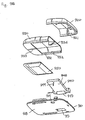
- a drug infusion device 901 comprises a base plate 910, a first cover member 920 and a second cover member 930, the three elements in combination forming a housing in which a pump assembly 940 and a flexible drug reservoir 950 are arranged.
- the base plate comprises a lower generally planar surface 918 adapted to be mounted in engagement with a skin-surface of a user, and an upper surface 919 provided with connecting means allowing the first and second cover members as well as a pump assembly 940 to be mounted on the base plate. More specifically, the base plate comprises three upstanding hook-members 911 adapted to engage corresponding hook structures 921 on the first cover member to thereby lock the two members to each other in a snap-action manner, as well as a pair of parallelly arranged opposed members 912 having outwardly open grooves adapted to engage corresponding flange structures 931 on the second cover member allowing the two members to be mounted in sliding engagement with each other.
- the grooves and the flanges may be provided with corresponding ratchet or locking means 916, 932.
- the base plate comprises a ridge member 913 adapted to engage a corresponding groove structure 933 on the second cover member.
- the base plate member further comprises an aperture 914, a part-cylindrical "female" hinge member 915 adapted to engage the pump assembly, as well as an opening 917 associated with the hinge member.
- the pump assembly 940 comprises a membrane pump as well as control means, actuating means (e.g. heating means), contact means and an energy source for driving the pump.
- the pump assembly is configured with a (part) cylindrical hinge body 941 from which protrudes a pump body 942 wherein the pump and driving means are arranged.
- the pump inlet is in fluid communication with an inlet needle 943 protruding axially from an end of the hinge body and the pump outlet is in fluid communication with an infusion needle 944 protruding from a lower surface 948 of the pump body, both needles having a pointed free end.
- the hinge body is adapted to be pivotally received in the hinge member 915 with the engagement member 947 arranged in the opening 917 to prevent axial displacement of the pump assembly, and with the infusion needle in alignment with the aperture 914.
- the flexible reservoir 950 is in the form of a pouch- or bag-like member formed from a pliable material and provided with a needle penetratable connecting means, e.g. a self-sealing septum (not shown).
- the reservoir is easily collapsible allowing the drug contained therein to be sucked out by the pump without the need for additional venting means.
- the reservoir is mounted and hold in place under the second cover member by appropriate means.
- the reservoir is prefilled with a drug such as insulin, however, the reservoir may also be adapted to be filled by the user prior to user.
- the above-described components are assembled in two subassemblies (see figs. 9C and 9D ), a main assembly 960 and a reservoir assembly 970, this allowing the assemblies to be sterilized independently if necessary.
- the main assembly comprises the base plate member with the first housing member mounted on top thereof providing a cavity in which the pump assembly 940 is pivotally arranged in the hinge member 915
- the reservoir assembly comprises the second housing member with the reservoir mounted corresponding to a lower surface thereof.
- the hinge may be configured to provide an upwardly biasing force preventing the pump assembly from pivoting downwardly.
- the second housing member is provided with an end portion having a grooved area 934 and an oppositely arranged shroud portion 935 adapted to slide under the first cover member, as well as a lower ramp member 936 associated with the lower surface of the second housing member, the function of which will be explained in greater detail below.
- the drug infusion device 901 is supplied to the user with the two subassemblies assembled corresponding to an initial state as shown in fig. 9E . More specifically, the reservoir assembly is mounted in sliding engagement with the base plate member by means of the connecting members 912, 931, a cavity inclosing the reservoir thereby being formed between the second cover member and the base plate member, the reservoir connecting means being arranged in axial alignment with the inlet needle. In the initial state the reservoir assembly is not fully moved towards the first cover member, however, the shroud is partially inserted under the first cover member, this providing a closed cavity.
- the locking or ratchet means 916, 932 arranged between the second cover member and the base plate member may be configured to prevent that the reservoir assembly can be removed by the user.
- the reservoir assembly is moved towards the pump assembly (see fig. 9F ) whereby a number of actions takes place. More specifically, the inlet needle 943 will penetrate the reservoir connecting means providing fluid communication between the reservoir and the pump, and the ramp 936 on the second cover member will engage the pump assembly to thereby pivot it downwardly whereby the infusion needle 944 will be moved through the aperture 914.
- contact means arranged on the pump assembly e.g. on the lower surface of the pump body
- the activated control means may be adapted to "wait" for a command signal from an external signal (e.g. supplied from a remote control device) before the pump is actuated.
- the reservoir assembly and the pump assembly may be adapted to move linearly, e.g. in a colinear fashion when arranged in a "stack".
- the reservoir may be connected to the pump, the pump being started, and the needle introduced partly or fully independently of each other, e.g. by two or three user actuated actions.
- the drug infusion device 901 may be used in the following way. After the liner has been removed the device is place on a suitable skin portion of the user, e.g. in the abdominal region after which the reservoir assembly serving as a button (indicated by the grooved area 931) is pushed towards the main portion until it locks in place, this, as described above, resulting in activation of the pump and introduction of the needle subcutaneously through the skin of the user.
- the pump may start to operate immediately or it may wait for user activated commands before pump action is initiated, e.g. commands received from a remote commander or from input means arranged on the device.
- the pump Before infusion in accordance with a given (basal) infusion rate begins, the pump will advantageously perform a priming action as described above. As the volume of air initially trapped in the infusion pump and the associated conduits (including the two needles) normally is very small, it will in most cases be acceptable to expel this volume of air into the user, however, if this is not desirable, actuation of the infusion device (i.e. pushing the two assemblies together) will have to be performed before the device is mounted on the skin.
- the device When the device is to be removed, it may be pulled of the skin in its active state with the needle protruding from the lower surface, or the device may be reversed to its initial state before it is removed.
- the locking means may be released by pushing down the upper surface of the first cover member.
- the needle has been in the form of a unitary needle device (e.g. an infusion needle as shown or a needle sensor (not shown)), however, a needle device (e.g. a soft cannula or a soft needle sensor) may also be introduced subcutaneously in combination with an insertion needle which is withdrawn after insertion thereof.
- a needle device e.g. a soft cannula or a soft needle sensor
- the needle unit comprises an insertion needle having a distal pointed end, the insertion needle being removeably arranged co-axially with and supporting the distal needle portion (e.g. of a needle sensor), the insertion needle and the needle being arranged to be simultaneously pivoted from their respective first position to their respective second position when the needle unit is actuated.
- the insertion needle may have any desirable configuration such as solid or grooved.
Abstract
Description
- The present invention generally relates to the insertion of transcutaneous devices such as needles, needle-like members and cannulas. More specifically, the invention relates to insertion of a transcutaneous device at a selected site within the body of a subject for subcutaneous, intravenous, intramuscular or intradermal delivery of a drug to the subject, the transcutaneous device being carried by a device comprising a mounting surface adapted for application to the skin of the subject. Especially, the invention relates to insertion of an infusion needle or cannula for the infusion of a drug, to insertion of a needle-formed sensor, as well as to insertion of insertion needles for easy placement of a device such as a sensor through the skin of a subject.
- In the disclosure of the present invention reference is mostly made to the treatment of diabetes by injection or infusion of insulin, however, this is only an exemplary use of the present invention.
- Portable drug delivery devices for delivering a drug to a patient are well known and generally comprise a reservoir adapted to contain a liquid drug and having an outlet in fluid communication with a hollow infusion needle, as well as expelling means for expelling a drug out of the reservoir and through the skin of the subject via the hollow needle. Such devices are often termed infusion pumps.
- Basically, infusion pumps can be divided into two classes. The first class comprises durable infusion pumps which are relatively expensive pumps intended for 3-4 years use, for which reason the initial cost for such a pump often is a barrier to this type of therapy. Although more complex than traditional syringes and pens, the pump offer the advantages of continuous infusion of insulin, precision in dosing and optionally programmable delivery profiles and user actuated bolus infusions in connections with meals.
- Addressing the above problem, several attempts have been made to provide a second class of drug infusion devices that are low in cost and convenient to use. Some of these devices are intended to be partially or entirely disposable and may provide many of the advantages associated with an infusion pump without the attendant cost and inconveniencies, e.g. the pump may be prefilled thus avoiding the need for filling or refilling a drug reservoir. Examples of this type of infusion devices are known from
US patents 4,340,048 and4,552,561 (based on osmotic pumps),US patent 5,858,001 (based on a piston pump),US patent 6,280,148 (based on a membrane pump),US patent 5,957,895 (based on a flow restrictor pump (also know as a bleeding hole pump)),US patent 5,527,288 (based on a gas generating pump), orUS patent 5,814,020 (based on a swellable gel) which all in the last decades have been proposed for use in inexpensive, primarily disposable drug infusion devices. - The disposable pumps generally comprises a skin-contacting mounting surface adapted for application to the skin of a subject by adhesive means, and with the infusion needle arranged such that in a situation of use it projects from the mounting surface to thereby penetrate the skin of the subject, whereby the place where the needle penetrates the skin is covered while the appliance is in use.
- The infusion needle may be arranged to permanently project from the mounting surface such that the needle is inserted simultaneously with the application of the infusion pump. Examples of this configuration can be found in
US patents 2,605,765 ,4,340,048 and inEP 1 177 802US patent 5,851,197 discloses an injector in which an infusion set comprising a skin-mountable surface with a protruding needle can be mounted, the injector upon actuation driving the entire infusion set into contact with a skin portion whereby the needle is inserted through the skin. - Addressing the above problem, infusion pump devices have been proposed in which the pump device is supplied to the user with the needle in a retracted state, i.e. with the distal pointed end of the needle "hidden" inside the pump device, this allowing the user to place the pump device on the skin without the possibility of observing the needle. When first the needle is hidden, at least some of the fear is overcome making the introduction of the needle in a second step less problematic.
US patents 5,858,001 and5,814,020 disclose infusion devices of this type in which an infusion needle is arranged in an upper housing portion pivotably arranged relative to a base plate portion. In this way the user can introduce the needle by pressing the upper portion into engagement with the base plate portion. - To further reduce the fear and pain associated with the introduction of the needle, many recent pump devices have been provided with actuatable needle insertion means, which just has to be released by the user after which e.g. spring means quickly will advance the needle through the skin.
- For example,
US patent 5,957,895 discloses a liquid drug delivery device comprising a bent injection needle which is adapted to project through a needle aperture in the bottom surface of the housing in a situation of use. A movable needle carrier is disposed in the housing for carrying the injection needle and for causing the injection end of the needle to project through the needle aperture upon movement of the needle carrier. -
US patent 5,931,814 discloses an infusion device having a housing with a drug reservoir, an infusion needle (or cannula) communicating with the reservoir, means for inserting the needle, and pump means for discharging the reservoir contents through the needle. The needle is fixed relative to the housing and projects beyond the lower skin-contacting surface of the housing to the depth required for injection. The needle is surrounded by a protective element which is moved by spring means from a first end position in which the protective device projects beyond the lower surface of the housing and beyond the needle to a second end position in which the protective device does not project beyond the underside of the casing.WO 02/15965 - In the devices disclosed in
US patents 5,957,895 and5,931,814 the needle is automatically inserted by the release of pre-tensioned spring means arranged within the devices, whereas in the device known fromWO 02/15965 - In the above primarily infusion devices has been discussed, however, the problem of inserting a needle-formed device through the skin of a subject also relates to other fields, e.g. the introduction of needle-formed sensors comprising sensor means capable of being influenced by a body substance and producing a signal corresponding thereto (e.g. blood glucose).
- Having regard to the above-identified problems, it is an object of the present invention as claimed to provide an insertion means for a transcutaneous device mounted in a device and which allows for easy and swift insertion of the transcutaneous device, yet is reliable in use. The device should be compact in size and be designed for cost effective manufacturing.
- Correspondingly, a medical device is provided as defined in
claim 1, the two-part form being based uponUS 5,858,001 .WO 2004/029457 has been cited with reference to Art. 54(3) EPC, the document disclosing a transcutaneous device unit containing a pump as well as pump actuating means. - The transcutaneous device may e.g. be in the form of a pointed hollow infusion needle or a combination of a relatively flexible per se blunt cannula with a pointed insertion needle may provide a pointed transcutaneous device, the insertion needle being retractable after insertion of the blunt portion of the transcutaneous device. The cannula is advantageously soft and flexible relative to the insertion needle which typically is a solid steel needle. However, the transcutaneous device may also be a composite structure comprising a distal portion, a proximal portion and an intermediate portion provided by different types of conduits. For example, a transcutaneous device unit may comprise a distal portion in the form of a cannula in combination with an insertion needle, a proximal portion in the form of a hollow infusion-type needle, and an intermediate portion connecting the distal and proximal portions and being formed in a carrier member in which the distal and proximal portions are mounted. The distal portion may also be in the form of a micro needle array. In the disclosure of the present invention as well as in the description of the exemplary embodiments, reference will mostly be made to a transcutaneous device in the form of a hollow infusion needle.
- By this arrangement a distal end of a transcutaneous device can be moved between a retracted state and an extended state, yet providing a proximal end allowing a high degree of flexibility and reliability for connection to a fluid reservoir. For example, a fluid reservoir may be (or may be brought) in fluid communication with proximal end of the transcutaneous device before the needle unit is pivoted, or the fluid reservoir may be brought in fluid communication with the proximal end of the transcutaneous device during or after the transcutaneous device unit is pivoting. The only requirement for allowing this arrangement would be that the fluid connection allows rotation of the proximal transcutaneous device end and is moved axially corresponding to the pivoting axis.
- Correspondingly, in an exemplary embodiment a medical device is provided, further comprising a reservoir adapted to contain a liquid drug and comprising in a situation of use an outlet in fluid communication with the transcutaneous device, and expelling means for expelling a drug out of the reservoir and through the skin of the subject via the transcutaneous device.
- The reservoir advantageously comprises outlet means adapted to cooperate with the proximal portion of the transcutaneous device (thus serving as an inlet portion), the outlet means being arranged substantially corresponding to the pivoting axis, thereby allowing the transcutaneous device unit to pivot substantially without non-rotational displacement of the inlet portion of the transcutaneous device relative to the outlet means. In such an arrangement the reservoir and the inlet portion may be arranged moveable relative to each other, corresponding substantially to the pivoting axis, between a disconnected position in which there is no fluid communication between the reservoir and the inlet portion, and a connected position in which fluid communication between the reservoir and the inlet portion is established. Advantageously, the inlet portion of the transcutaneous device comprises a pointed proximal end, and the outlet means of reservoir comprises a needle-penetratable septum, e.g. a self-sealing elastomeric septum.
- The transcutaneous device unit may be inserted manually, or the medical device may comprise actuatable driving means disposed within the housing and adapted to pivot the transcutaneous device unit from the first position to the second position. The driving means may be actuated by actuation means moveable, relative to the housing, from a first position to a second position thereby actuating the driving means. In an exemplary embodiment the reservoir is connected to the actuation means, whereby movement of the actuation means between the first and the second position causes the reservoir to be arranged in fluid communication with the transcutaneous device.
- In an advantageous embodiment, the device comprises common actuation means moveable, relative to the housing, from a first position to a second position thereby actuating the driving means, wherein the reservoir is connected to the actuation means such that movement of the actuation means between the first and the second position causes the reservoir to be arranged in fluid communication with the transcutaneous device, the inlet portion of the transcutaneous device being introduced through the needle-penetratable septum either before or after the transcutaneous device unit is pivoted from the first position to the second position.
- The transcutaneous device unit may be in the form of a "naked" needle, however, in advantageous embodiments the transcutaneous device unit comprises a carrier for the transcutaneous device, the transcutaneous device being carried by (or formed integrally with) the carrier, the carrier being connected to the housing by the hinge. The hinge may be provided by cooperating members of the carrier respectively the housing, or the carrier and the housing may be formed integrally connected to each other by a film-hinge.
- Normally the transcutaneous device carrier would serve only as a carrier, however, the carrier may be provided with a pump for pumping a liquid between the inlet and outlet portion of the transcutaneous device.
- For any of the above-described embodiments, the mounting surface advantageously comprises adhesive means for adhering the first unit to the skin of the subject.
- As used herein, the term "drug" is meant to encompass any drug-containing flowable medicine capable of being passed through a delivery means such as a hollow needle in a controlled manner, such as a liquid, solution, gel or fine suspension. Representative drugs include pharmaceuticals such as peptides, proteins (e.g. insulin, insulin analogues and C-peptide), and hormones, biologically derived or active agents, hormonal and gene based agents, nutritional formulas and other substances in both solid (dispensed) or liquid form. In the description of the exemplary embodiments reference will be made to the use of insulin. Correspondingly, the term "subcutaneous" infusion is meant to encompass any method of transcutaneous delivery to a subject. Further, the term needle (when not otherwise specified) defines a piercing member adapted to penetrate the skin of a subject.
- In the following the invention will be further described with references to the drawings, wherein
-
fig. 1A shows in a perspective view a first embodiment of a medical device gripped by a user corresponding to a first state of use, -
fig. 1B shows the device offig. 1A with a portion of the housing cut off, -
fig. 1C shows the device offig. 1A with a portion of the housing removed, -
fig. 1D shows the device offig. 1A seen from a different angle with a portion of the housing cut off, -
fig. 1E shows the device offig. 1D with a portion of the housing removed, -
figs. 2A-2E shows an intermediate state of use corresponding tofigs. 1A-1E , -
figs. 3A-3E shows a second state of use corresponding tofigs. 1A-1E , -
fig. 4A shows in a perspective view a second embodiment of a medical device gripped by a user corresponding to a first state of use, -
fig. 4B shows the device offig. 4A with a portion of the housing cut off, -
fig. 4C shows the device offig. 4A with a portion of the housing removed, -
fig. 4D shows the device offig. 4A seen from a different angle with a portion of the housing cut off, -
fig. 4E shows the device offig. 4D with a portion of the housing removed, -
figs. 5A-5E shows an intermediate state of use corresponding tofigs. 4A-4E , -
figs. 6A-6E shows a second state of use corresponding tofigs. 4A-4E , -
fig. 7A shows a transcutaneous device unit, -
fig. 7B shows a further transcutaneous device unit, -
figs. 8A-8D shows different expelling means suitable for use with the invention, -
fig. 9A shows an exploded view of a drug infusion device seen from above, -
fig. 9B shows an exploded view of the infusion device seen offig. 9A from below, -
figs. 9C and 9D shows the infusion device comprising two sub-assemblies, -
fig. 9E shows the infusion device in an assembled initial state, -
fig. 9F shows the infusion device in an assembled actuated state, and -
figs. 10A-10C show in a schematic representation a cannula and insertion needle combination implemented in a device. - In the figures like structures are identified by like reference numerals.
- When in the following terms as "upper" and "lower", "right" and "left", "horizontal" and "vertical" or similar relative expressions are used, these only refer to the appended figures and not to an actual situation of use.
-
Figs. 1-3 show in schematic representations perspective views of different states of use of a medical device in accordance with the invention. Correspondingly, the configuration of the different structures as well as there relative dimensions are intended to serve illustrative purposes only. - More specifically,
fig. 1A shows a first embodiment of amedical device 100 gripped by a user. The medical device comprises a housing with anupper housing portion 110 and a lowerbase plate portion 120, the housing providing a cavity in which anactuation member 130 is slidingly received through an opening, the actuation element being moveable corresponding to a longitudinal direction in respect of the device. The base plate portion comprises an adhesive mounting surface 121 adapted for application to the skin of a subject, the mounting surface being generally planar and defining a general plane. The actuation member comprises a ribbed area allowing for easy gripping by a user, e.g. using the first and second fingers as shown. - In the shown embodiment the actuation member is formed as a frame having opposed
side portions 131, 132 adapted to be in sliding engagement with inner surface portions of the upper housing portions, the inner surface portions comprising longitudinally ridges received in corresponding grooves formed on the outer surfaces of the side portions. The two side portions are connected by abutton portion 135 corresponding to an outer end and by a bridge portion 134 corresponding to an inner end thereof, the bridge portion comprising a spring means in the form of aleaf spring 137 having a free end portion with an inclined orientation relative to the base plate portion, the leaf spring serving as an insertion spring. The leaf spring may be attached to the bridge portion (e.g. when made from a metal alloy) or it may be formed integrally with the actuation member (e.g. manufactured from a polymer). The base plate portion comprises an upper surface on which afemale hinge member 138 and a ramp member 139 are formed, preferably formed integrally with the base plate portion. The ramp member comprises an upper inclined ramp surface 147 adapted to engage a lower surface of the leaf spring 137 (serving as a drive portion adapted to engage a corresponding engagement portion on the needle unit), the ramp surface terminating in an upper free edge 148. - The device further comprises a
needle unit 150 connected to the base plate portion by a hinge allowing the needle unit to pivot corresponding to a pivoting axis defined by the hinge, the pivoting axis being arranged substantially in parallel with the mounting surface. The needle unit comprises a hollow infusion needle (seefig. 7A ) having a distalpointed outlet portion 151 adapted to penetrate the skin of the subject, the outlet portion extending generally perpendicular to the mounting surface, and a pointedproximal inlet portion 152 arranged substantially corresponding to the pivoting axis. The distal end may be straight or curved, e.g. arcuate corresponding to the pivoting axis. The needle is carried by a needle carrier comprising anarm portion 153 and a cylindrical male hinge portion, the needle carrier being connected to the female hinge member thereby forming the hinge. The arm comprises a biasing member in the form of aleaf spring 155 projecting therefrom, the spring being in engagement with the upper surface of the base plate member thereby providing an upwardly directed biasing force forcing the needle into its initial position. - By this arrangement the needle unit can pivot between an initial position in which the inlet portion of the needle is retracted within the housing, and a second position in which the inlet portion projects relative to the mounting surface through an opening (not to be seen in the figs.) formed in the base plate portion. In the disclosed embodiments the hinge is provided by cooperating members of the needle carrier respectively the housing, however, a "naked" needle may be connected to the housing or the needle carrier and the housing may be formed integrally connected to each other by a film-hinge.
- The device further comprises a reservoir 160 adapted to contain a liquid drug and comprising in a situation of use an outlet in fluid communication with the infusion needle, and expelling means (not shown for better illustrating the principles of the invention) for expelling a drug out of the reservoir and through the skin of the subject via the hollow needle. The reservoir and the expelling means are mounted on the actuation member and thus moveable relative to the housing. The reservoir comprises a needle-
penetratable septum 161 adapted to cooperate with the inlet portion of the infusion needle, the septum being arranged substantially corresponding to the pivoting axis, thereby allowing the needle unit to pivot substantially without non-rotational displacement of the inlet portion of the infusion needle relative to the septum. - With reference to
figs. 2 and3 use and actuation of thedevice 100 will be described. - After having placed the medical device on a skin portion, the user presses the
actuation member 130 into the housing whereby the needle is inserted and the delivery means started. During this action the actuation member is moved from a first (initial) position through an intermediate position to a second position. During movement of the actuation member from the first to the intermediate position theinsertion spring 137 is moved relative to the ramp member, this causing an upwards activation movement of the drive portion whereby energy is releasably stored in the spring, and a displacement movement in which the drive portion is moved to a position above the engagement portion of the needle unit. At the same time the reservoir is moved into fluid communication with the infusion needle. After this, actuation of the actuation member from the intermediate to the second position causes release of the activated spring (when the distal free edge of the insertion spring slides over the upper free edge of the ramp, whereby the insertion spring in a snap-action engages the needle unit thereby biasing it downwardly to its second position against the force of the biasingspring 155. At the same time the actuation member is locked in place by the insertion spring being locked behind the ramp member. - The delivery means or sensor electronics will have to be actuated in combination with insertion of the needle, either in combination with the above-described actuation of the needle (e.g. by closing an electric contact or by providing a fluid communication) or by using additional actuation means which may be operated separately after the device has been mounted on the skin and the needle introduced.
- In
figs. 4-6 is shown a second embodiment of amedical device 200 similar to the first embodiment, the device comprising anupper housing portion 210 and a lower base plate portion 220, the housing providing a cavity in which anactuation member 230 is slidingly received through an opening, the actuation element being moveable corresponding to a longitudinal direction. The device further comprises areservoir 260 and aneedle unit 250. The device also comprises aninserter spring 237 and aramp member 247, however, in contrast to the first embodiment the inserter spring is in the form of a thin rod just as the ramp member is arranged to deflect the inserter spring upwards as well as sidewards. - More specifically, the ramp surface is somewhat longer and has a concave cross-sectional configuration, this allowing the rod spring to slide thereon without accidental disengagement. The ramp terminates in an obliquely oriented
deflection wall 249 which will force the spring rod outwards when forced thereagainst. The rod may be formed integrally with the actuation member or attached as a separate member, e.g. as a metal string. The needle unit is similar to the first embodiment apart from comprising a separately formedengagement portion 257 projecting from the distal end of the carrier arm and arranged on the side of the ramp member just below the deflection wall. Further, in contrast to the first embodiment, the actuation member does not comprise a bridge portion connecting the inner ends of the side portions. - In use, the second embodiment is actuated in the same way as the first embodiment, the primary difference being that the insertion spring is released from the upper ramp surface by a sidewards movement provided by the deflection wall.
- In the above described embodiments, the actuation member has been moved linearly, however, it may other movements may be utilized in accordance with the invention. For example, a medical device may have a circular configuration in which actuation may be provided by the user rotating an upper portion of the housing. In such an arrangement the insertion spring may extend radially with a free peripheral end sliding on a curved ramp.
-
Fig. 7A shows aneedle unit 150 adapted to be connected to a housing member by a hinge allowing the needle unit to pivot corresponding to a pivoting axis defined by the hinge. More specifically, the needle unit comprises a needle carrier having acylindrical hinge portion 154 defining the pivoting axis, and anarm member 153 extending perpendicularly from the hinge portion in respect of the pivoting axis. On a lower surface of the arm member a biasing means is arranged in the form of aleaf spring member 155 adapted to engage a portion of the housing. The needle carrier carries a needle having a distalpointed portion 151 adapted to penetrate the skin of the subject, the distal portion extending generally perpendicular to the mounting surface, and a proximal portion (152) arranged substantially corresponding to the pivoting axis. In this way the needle unit can be arranged to pivot between a first position in which the distal portion of the needle is retracted within a housing, and a second position in which the inlet portion projects relative to a mounting surface. In case the distal portion is in the form of cannula, the arm member may be provided with a needle-penetratable septum 159 allowing an insertion needle to be inserted through the cannula as shown infig. 9A . In the shown embodiment the carrier may be injection moulded around a needle, however, the carrier may also be formed from sheet metal to which a needle is attached e.g. by adhesive or welding. - Thus
fig. 7B shows a further embodiment of aneedle unit 550 adapted to be connected to a housing member to thereby allow the needle unit to pivot corresponding to a pivoting axis defined by a hinge. More specifically, the needle unit comprises a needle carrier formed from a bent sheet metal member, the carrier comprising anupper arm 560 and alower arm 570 connected to each other by ahinge portion 580 allowing the arms to pivot corresponding to a pivoting axis defined by the hinge. The lower arm forms atray 571 in which ahollow infusion needle 590 is mounted (e.g. by welding or adhesive), the needle having a distalpointed portion 591 adapted to penetrate the skin of the subject, the distal portion extending generally perpendicular to the mounting surface of a device in which it in a situation of use is mounted, and aproximal portion 592 arranged substantially corresponding to the pivoting axis. Thus, when a portion of the upper arm, e.g. the surface, is attached to a device housing, the lower arm can pivot between a first position in which the distal portion of the needle is retracted within a housing, and a second position in which the inlet portion projects relative to a mounting surface. The lower arm may be moved by external means, however, advantageously the needle unit provides the drive means for moving the lower arm between the two positions. This may be provided by the elastic properties of the sheet material per se corresponding to the hinge portion, or an additional spring may be provided between the two arms to thereby urge them apart. To lock the lower part in an energized, releasable first position, the upper arm is provided with aflexible release arm 562 comprising acatch 563 at the distal end thereof supporting and arresting the lower arm in its first position. When the distal end and the catch are moved away from the lower arm, the flexible properties of the hinge and/or the spring will bias the lower arm to its second position. - In the above described embodiments, the transcutaneous device has been in the form of a unitary needle device (e.g. an infusion needle as shown or a needle sensor (not shown)), however, the transcutaneous device may also be in the form of a combination of cannula or a sensor in combination with an insertion needle which is withdrawn after insertion thereof.
- Thus,
figs. 10A-10C show in a schematic representation how a cannula and insertion needle combination can be implemented in a device 300 (partly shown) of the type described with reference tofigs. 4-6 . More specifically, atranscutaneous device unit 350 of the type shown infig. 7 is provided, however, in contrast to theneedle unit 150 the transcutaneous device unit comprises a combination of a relatively soft cannula 351 (which e.g. may be of the soft "Teflon®" type) carried by alower arm portion 353 and a pointed insertion needle 361 (e.g. made from medical grade stainless steel) slidably arranged within the cannula and carried by anupper arm portion 363, both arm portions being attached to a hinge portion (not shown). The lower arm further comprises aseal member 367 through which the insertion needle is arranged. The cannula and the insertion needle may be straight or curved, e.g. arcuate corresponding to the pivoting axis. The two arms comprise mating coupling means 367, 357 locking the arms together in an initial position with distal end of the insertion needle extending from the distal opening of the cannula as shown infig. 10A . The cannula is provided with locking means adapted to engage the housing of the device when the cannula has been moved to an extended position. Between the housing of the device and the flexible arm aspring member 368 is arranged biasing the flexible arm upwards. Corresponding to thefig. 4 embodiment, the device also comprises aninserter spring 337 and aramp member 347, as well as acoupling release member 348. - In a situation of use the inserter spring is energized by being moved up the ramp by the user and then released to engage the lower arm to thereby pivot the transcutaneous device unit towards the extended position as shown in
fig. 10B . In its fully extended position the locking means of the cannula engages the housing of the device (here: an opening in the lower surface) and thecoupling release member 348 engages the arm coupling means to thereby release the upper arm from the lower arm whereby the upper arm is moved towards its initial position by thespring member 368, thereby withdrawing the insertion needle from the cannula, seefig. 10C . In the shown embodiment the cannula is irreversibly locked to the housing, however, advantageously releasable locking means is provided between the lower arm (or cannula) and the housing, this allowing the cannula to be withdrawn from its extended position before or after the used device is removed from the skin portion to which it has been attached. - In the above-described embodiments a medical device has been described comprising a reservoir, however, for better illustrating the principles of the present invention, the means for expelling a drug from the reservoir has been omitted in the figures. Such expelling means, which as the reservoir does not form part of the present invention in its basic form, may be of any type which would be suitable for arrangement within a skin-mountable drug delivery device. Further, as the needle of the present invention also may be in the form of a needle sensor, the interior of the medical device may comprise sensor means adapted to cooperate with the needle sensor.
- In
figs. 8A-8D examples of expelling means suitable for use with the present invention are shown schematically, however, these are merely examples. More specifically,fig. 8A shows a pump arrangement comprising a drug-containing cartridge 1010 having adistal closure member 1011 allowing a needle to be connected, and apiston 1015 slidingly arranged there within, a flexible toothed piston rod 1020 (for example as disclosed inUS patent 6,302,869 ), anelectric motor 1030 which via a worm-gear arrangement 1031 drives the piston rod to expel drug from the cartridge, the motor being controlled by control means 1040 and the energy for the control means and the motor being provided by abattery 1050. The pump may be activated when the needle is inserted (by means not shown) or by separate user-actuatable means (not shown) after the inserter has been detached form the delivery device. -
Fig. 8B shows a pump arrangement comprising a drug-containingcartridge 1110 having distal andproximal closure members 1111, 1112, and apiston 1115 slidingly arranged there within, gas generating means 1120 in fluid communication with the interior of the cartridge viaconduit 1121 for driving the piston to expel drug from the cartridge, the gas generating means being controlled by control means 1140 and the energy for the control means and the gas generation being provided by a battery 1150. The pump may be activated as indicated above. A detailed disclosure of such gas generating means for a drug delivery device can be found in e.g.US patent 5,858,001 . -
Fig. 8C shows a pump arrangement comprising a drug-containing cartridge 1210 having distal andproximal closure members piston slidingly 1215 arranged there within, anosmotic engine 1220 in fluid communication with the interior of the cartridge viaconduit 1221 for driving the piston to expel drug from the cartridge. The osmotic engine comprises a firstrigid reservoir 1225 containing a salt-solution and a secondcollapsible reservoir 1226 containing water, the two reservoirs being separated by asemi-permeable membrane 1227. When supplied to the user, thefluid connection 1228 between the second reservoir and the membrane is closed by a user-severable membrane (e.g. a weak weld) which, when severed, will allow the osmotic process to start as water is drawn from the second reservoir through the membrane and into the first reservoir. The pump may be activated as indicated above. A detailed disclosure of the osmotic drive principle can be found in e.g.US patent 5,169,390 . -
Fig. 8D shows a pump arrangement comprising a drug-containingflexible reservoir 1310 arranged within a rigid fluid-filledsecondary reservoir 1311 in fluid communication with aprimary reservoir 1320 through aconduit 1330 comprising a flow restrictor 1331. The primary reservoir is in the form of a cartridge with amoveable piston 1321 and contains a viscous drive fluid. A spring is arranged to act on the piston to drive fluid from the first to the second reservoir thereby expelling drug from the flexible reservoir when the latter is connected to an infusion needle (not shown). The flow rate will be determined by the pressure generated by the spring in the drive fluid, the viscosity of the drive fluid and the flow resistance in the flow restrictor (i.e. bleeding hole principle). The pump may be activated by straining the spring or by releasing a pre-stressed spring, either when the needle is inserted (by means not shown) or by separate user-actuatable means (not shown) after the inserter has been detached form the delivery device. An example of this principle used for drug infusion is known fromDE 25 52 446 . In an alternative configuration, the drug reservoir may be pressurized directly to expel the drug via a flow restrictor, e.g. as disclosed inUS patent 6,074,369 . - In the above-described embodiments the needle unit has been adapted primarily for actuation by actuatable driving means, however, with reference to
figs. 9A-9F a drug infusion device is shown which is adapted for manual actuation by moving an actuation member in parallel with the mounting surface. - More specifically, a
drug infusion device 901 comprises abase plate 910, afirst cover member 920 and asecond cover member 930, the three elements in combination forming a housing in which apump assembly 940 and aflexible drug reservoir 950 are arranged. - The base plate comprises a lower generally
planar surface 918 adapted to be mounted in engagement with a skin-surface of a user, and anupper surface 919 provided with connecting means allowing the first and second cover members as well as apump assembly 940 to be mounted on the base plate. More specifically, the base plate comprises three upstanding hook-members 911 adapted to engagecorresponding hook structures 921 on the first cover member to thereby lock the two members to each other in a snap-action manner, as well as a pair of parallelly arranged opposedmembers 912 having outwardly open grooves adapted to engage correspondingflange structures 931 on the second cover member allowing the two members to be mounted in sliding engagement with each other. In order to control movement between the two members, the grooves and the flanges may be provided with corresponding ratchet or locking means 916, 932. To help align the second cover member as it is moved towards the first cover member, the base plate comprises aridge member 913 adapted to engage acorresponding groove structure 933 on the second cover member. The base plate member further comprises anaperture 914, a part-cylindrical "female"hinge member 915 adapted to engage the pump assembly, as well as anopening 917 associated with the hinge member. - The
pump assembly 940 comprises a membrane pump as well as control means, actuating means (e.g. heating means), contact means and an energy source for driving the pump. The pump assembly is configured with a (part)cylindrical hinge body 941 from which protrudes apump body 942 wherein the pump and driving means are arranged. On the lower surface of the hinge body anengagement member 947 is arranged. The pump inlet is in fluid communication with aninlet needle 943 protruding axially from an end of the hinge body and the pump outlet is in fluid communication with aninfusion needle 944 protruding from alower surface 948 of the pump body, both needles having a pointed free end. The hinge body is adapted to be pivotally received in thehinge member 915 with theengagement member 947 arranged in theopening 917 to prevent axial displacement of the pump assembly, and with the infusion needle in alignment with theaperture 914. - The
flexible reservoir 950 is in the form of a pouch- or bag-like member formed from a pliable material and provided with a needle penetratable connecting means, e.g. a self-sealing septum (not shown). The reservoir is easily collapsible allowing the drug contained therein to be sucked out by the pump without the need for additional venting means. The reservoir is mounted and hold in place under the second cover member by appropriate means. In the shown embodiment the reservoir is prefilled with a drug such as insulin, however, the reservoir may also be adapted to be filled by the user prior to user. - The above-described components are assembled in two subassemblies (see
figs. 9C and 9D ), amain assembly 960 and areservoir assembly 970, this allowing the assemblies to be sterilized independently if necessary. More specifically, the main assembly comprises the base plate member with the first housing member mounted on top thereof providing a cavity in which thepump assembly 940 is pivotally arranged in thehinge member 915, and the reservoir assembly comprises the second housing member with the reservoir mounted corresponding to a lower surface thereof. The hinge may be configured to provide an upwardly biasing force preventing the pump assembly from pivoting downwardly. The second housing member is provided with an end portion having agrooved area 934 and an oppositely arrangedshroud portion 935 adapted to slide under the first cover member, as well as alower ramp member 936 associated with the lower surface of the second housing member, the function of which will be explained in greater detail below. - The
drug infusion device 901 is supplied to the user with the two subassemblies assembled corresponding to an initial state as shown infig. 9E . More specifically, the reservoir assembly is mounted in sliding engagement with the base plate member by means of the connectingmembers - To activate the infusion device, the reservoir assembly is moved towards the pump assembly (see
fig. 9F ) whereby a number of actions takes place. More specifically, theinlet needle 943 will penetrate the reservoir connecting means providing fluid communication between the reservoir and the pump, and theramp 936 on the second cover member will engage the pump assembly to thereby pivot it downwardly whereby theinfusion needle 944 will be moved through theaperture 914. At the same time contact means arranged on the pump assembly (e.g. on the lower surface of the pump body) will be activated, thereby activating the pump control means and eventually the pump, however, the activated control means may be adapted to "wait" for a command signal from an external signal (e.g. supplied from a remote control device) before the pump is actuated. In an alternative embodiment (not shown) the reservoir assembly and the pump assembly may be adapted to move linearly, e.g. in a colinear fashion when arranged in a "stack". In further alternative embodiments (not shown) the reservoir may be connected to the pump, the pump being started, and the needle introduced partly or fully independently of each other, e.g. by two or three user actuated actions. - The
drug infusion device 901 may be used in the following way. After the liner has been removed the device is place on a suitable skin portion of the user, e.g. in the abdominal region after which the reservoir assembly serving as a button (indicated by the grooved area 931) is pushed towards the main portion until it locks in place, this, as described above, resulting in activation of the pump and introduction of the needle subcutaneously through the skin of the user. Depending on the programming of the control means, the pump may start to operate immediately or it may wait for user activated commands before pump action is initiated, e.g. commands received from a remote commander or from input means arranged on the device. Before infusion in accordance with a given (basal) infusion rate begins, the pump will advantageously perform a priming action as described above. As the volume of air initially trapped in the infusion pump and the associated conduits (including the two needles) normally is very small, it will in most cases be acceptable to expel this volume of air into the user, however, if this is not desirable, actuation of the infusion device (i.e. pushing the two assemblies together) will have to be performed before the device is mounted on the skin. - When the device is to be removed, it may be pulled of the skin in its active state with the needle protruding from the lower surface, or the device may be reversed to its initial state before it is removed. For example, if locking means are arranged between the shroud and the first cover member, the locking means may be released by pushing down the upper surface of the first cover member.
- In the above described embodiments, the needle has been in the form of a unitary needle device (e.g. an infusion needle as shown or a needle sensor (not shown)), however, a needle device (e.g. a soft cannula or a soft needle sensor) may also be introduced subcutaneously in combination with an insertion needle which is withdrawn after insertion thereof.
- Thus, in a further embodiment the needle unit comprises an insertion needle having a distal pointed end, the insertion needle being removeably arranged co-axially with and supporting the distal needle portion (e.g. of a needle sensor), the insertion needle and the needle being arranged to be simultaneously pivoted from their respective first position to their respective second position when the needle unit is actuated. The insertion needle may have any desirable configuration such as solid or grooved.
- In the above description of the preferred embodiments, the different structures and means providing the described functionality for the different components have been described to a degree to which the concept of the present invention will be apparent to the skilled reader. The detailed construction and specification for the different components are considered the object of a normal design procedure performed by the skilled person along the lines set out in the present specification.
Claims (16)
- A medical device (100), comprising:- a housing (110, 120) having a mounting surface (121) adapted for application to the skin of a subject,- a transcutaneous device unit (150) connected to the housing thereby providing a hinge (138, 154, 580) allowing the transcutaneous device unit or a portion thereof to pivot corresponding to a pivoting axis defined by the hinge, the pivoting axis being arranged substantially in parallel with the mounting surface,- the transcutaneous device unit comprising a transcutaneous device, the transcutaneous device comprising a distal pointed portion (151) adapted to penetrate the skin of the subject, the distal portion extending generally perpendicular to the mounting surface, and a proximal portion (152) adapted to cooperate with an outlet of a reservoir,- wherein the transcutaneous device unit is pivotable between a first position in which the distal portion of the needle is retracted within the housing, and a second position in which the distal pointed portion projects relative to the mounting surface, characterized in that- transcutaneous device unit does not contain a pump or pump actuating means, and- the proximal portion (152) of the transcutaneous device unit is arranged substantially corresponding to the pivoting axis,- thereby allowing the transcutaneous device unit to pivot substantially without non-rotational displacement of the proximal portion of the transcutaneous device relative to the outlet.
- A medical device as defined in claim 1, further comprising:- a reservoir (160) adapted to contain a liquid drug and comprising in a situation of use an outlet in fluid communication with the transcutaneous device, and- expelling means for expelling a drug out of the reservoir and through the skin of the subject via the transcutaneous device.
- A medical device as defined in claim 2, wherein the reservoir comprises outlet means (161) adapted to cooperate with the proximal portion of the transcutaneous device, the outlet means being arranged substantially corresponding to the pivoting axis, thereby allowing the transcutaneous device unit to pivot substantially without non-rotational displacement of the proximal portion of the transcutaneous device relative to the outlet means.
- A medical device as defined in claim 3, wherein the reservoir and the proximal portion are moveable relative to each other substantially in parallel with the pivoting axis, between a disconnected position in which there is no fluid communication between the reservoir and the proximal portion of the transcutaneous device, and a connected position in which fluid communication between the reservoir and the proximal portion of the transcutaneous device is established.
- A medical device as defined in claim 4, wherein the proximal portion of the transcutaneous device comprises a pointed end, and the outlet means of reservoir comprises a needle-penetratable septum.
- A medical device as defined in any of the previous claims, further comprising actuatable driving means (137) disposed within the housing and adapted to pivot the transcutaneous device unit from the first position to the second position.
- A medical device as defined in claim 6, further comprising actuation means (130) moveable, relative to the housing, from a first position to a second position thereby actuating the driving means.
- A medical device as defined in claim 7, wherein the reservoir (160) is connected to the actuation means, whereby movement of the actuation means between the first and the second position causes the reservoir to be arranged in fluid communication with the infusion needle.
- A medical device as defined in claim 5, further comprising actuation means (130) moveable, relative to the housing, from a first position to a second position thereby actuating the driving means (137), wherein the reservoir is connected to the actuation means such that movement of the actuation means between the first and the second position causes the reservoir to be arranged in fluid communication with the transcutaneous device, the proximal portion of the transcutaneous device being introduced through the needle-penetratable septum either before or after the transcutaneous device unit is pivoted from the first position to the second position.
- A medical device as defined in any of the previous claims, wherein the transcutaneous device unit comprises a transcutaneous device carrier (153, 154, 550), the transcutaneous device being carried by the carrier, the carrier being connected to the housing.
- A medical device as defined in claim 10, wherein the transcutaneous device carrier comprises a pump (940) for pumping a liquid between the proximal and the distal portion of the transcutaneous device.
- A medical device as defined in any of the previous claims, wherein the transcutaneous device is a unitary hollow infusion needle forming the distal and proximal portions.
- A medical device as defined in any of the previous claims, wherein the distal portion is formed by a cannula (351) in combination with a pointed insertion needle (361) accommodated at least partially within the cannula, the cannula having a distal opening, wherein the insertion needle is arranged to be moveable away from the distal opening when the cannula and the insertion needle have been moved to their second position.
- A medical device as defined in any of the previous claims, wherein the transcutaneous device unit (550) comprises a carrier with first and second arms (570, 560) connected by a hinge (580) allowing the first portion to pivot corresponding to a pivoting axis defined by the hinge, the first arm comprising the transcutaneous device (590).
- A medical device as defined in claim 14, further comprising biasing means biasing the first arm from its first to its second position.
- A medical device as defined in claim 15, further comprising releasable coupling means (563) for holding the first arm in its first position against the biasing force of the biasing means.
Applications Claiming Priority (3)
| Application Number | Priority Date | Filing Date | Title |
|---|---|---|---|
| DKPA200300696 | 2003-05-08 | ||
| US47101103P | 2003-05-16 | 2003-05-16 | |
| PCT/DK2004/000332 WO2004098682A2 (en) | 2003-05-08 | 2004-05-10 | Pivotable injection needle unit |
Publications (2)
| Publication Number | Publication Date |
|---|---|
| EP1631336A2 EP1631336A2 (en) | 2006-03-08 |
| EP1631336B1 true EP1631336B1 (en) | 2010-02-17 |
Family
ID=36597060
Family Applications (1)
| Application Number | Title | Priority Date | Filing Date |
|---|---|---|---|
| EP04731881A Not-in-force EP1631336B1 (en) | 2003-05-08 | 2004-05-10 | Pivotable injection needle unit |
Country Status (6)
| Country | Link |
|---|---|
| US (1) | US7628770B2 (en) |
| EP (1) | EP1631336B1 (en) |
| CN (1) | CN100574819C (en) |
| AT (1) | ATE457761T1 (en) |
| DE (1) | DE602004025568D1 (en) |
| WO (1) | WO2004098682A2 (en) |
Families Citing this family (169)
| Publication number | Priority date | Publication date | Assignee | Title |
|---|---|---|---|---|
| AU2003245872A1 (en) | 2002-07-24 | 2004-02-09 | M 2 Medical A/S | An infusion pump system, an infusion pump unit and an infusion pump |
| AU2003280307A1 (en) | 2002-11-05 | 2004-06-07 | M 2 Medical A/S | A disposable wearable insulin dispensing device, a combination of such a device and a programming controller and a method of controlling the operation of such a device |
| ATE385814T1 (en) | 2002-12-23 | 2008-03-15 | M2 Medical As | MEDICAL DEVICE FOR DELIVERING INSULIN |
| WO2005072794A2 (en) * | 2004-01-29 | 2005-08-11 | M 2 Medical A/S | Disposable medicine dispensing device |
| CA2560784A1 (en) | 2004-03-26 | 2005-10-06 | Unomedical A/S | Infusion set |
| CA2559750C (en) | 2004-03-31 | 2014-01-07 | Eli Lilly And Company | Injection apparatus having a needle cassette for delivering a pharmaceutical liquid |
| US8062250B2 (en) | 2004-08-10 | 2011-11-22 | Unomedical A/S | Cannula device |
| US20060100581A1 (en) * | 2004-08-13 | 2006-05-11 | Mogensen Lasse W | Reservoir for front end loaded infusion device |
| DE102004039408A1 (en) | 2004-08-13 | 2006-03-02 | Disetronic Licensing Ag | Insertion head for medical or pharmaceutical applications |
| US9398882B2 (en) * | 2005-09-30 | 2016-07-26 | Abbott Diabetes Care Inc. | Method and apparatus for providing analyte sensor and data processing device |
| JP2008528086A (en) * | 2005-01-24 | 2008-07-31 | ノボ・ノルデイスク・エー/エス | Medical device with protected puncture device |
| US7985199B2 (en) * | 2005-03-17 | 2011-07-26 | Unomedical A/S | Gateway system |
| WO2006105793A1 (en) | 2005-04-06 | 2006-10-12 | M 2 Medical A/S | Method and device for dispensing liquid medicine by means of a twistable element |
| ATE480278T1 (en) | 2005-09-12 | 2010-09-15 | Unomedical As | INTRODUCTION SYSTEM FOR AN INFUSION SET WITH A FIRST AND SECOND SPRING UNIT |
| US8409142B2 (en) | 2005-09-26 | 2013-04-02 | Asante Solutions, Inc. | Operating an infusion pump system |
| US8057436B2 (en) | 2005-09-26 | 2011-11-15 | Asante Solutions, Inc. | Dispensing fluid from an infusion pump system |
| US8105279B2 (en) | 2005-09-26 | 2012-01-31 | M2 Group Holdings, Inc. | Dispensing fluid from an infusion pump system |
| US8551046B2 (en) | 2006-09-18 | 2013-10-08 | Asante Solutions, Inc. | Dispensing fluid from an infusion pump system |
| WO2007038060A2 (en) | 2005-09-26 | 2007-04-05 | M2 Medical A/S | Modular infusion pump having two different energy sources |
| US7534226B2 (en) | 2005-09-26 | 2009-05-19 | M2 Group Holdings, Inc. | Dispensing fluid from an infusion pump system |
| DE602006008494D1 (en) | 2005-11-08 | 2009-09-24 | M2 Medical As | INFUSION PUMP SYSTEM |
| WO2007056592A2 (en) | 2005-11-08 | 2007-05-18 | M2 Medical A/S | Method and system for manual and autonomous control of an infusion pump |
| US9615851B2 (en) * | 2005-11-11 | 2017-04-11 | Waveform Technologies, Inc. | Method and apparatus for insertion of a sensor |
| RU2419460C2 (en) | 2005-12-23 | 2011-05-27 | Уномедикал А/С | Injection device |
| AU2007219546B8 (en) | 2006-02-28 | 2012-07-05 | Unomedical A/S | Inserter for infusion part and infusion part provided with needle protector |
| CN101401313B (en) | 2006-03-13 | 2014-06-11 | 诺沃—诺迪斯克有限公司 | Secure pairing of electronic devices using dual means of communication |
| US8118509B2 (en) | 2006-05-08 | 2012-02-21 | Dianna Marcellus | Automatic substance applicator system |
| CN101460207B (en) | 2006-06-06 | 2012-03-21 | 诺沃-诺迪斯克有限公司 | Assembly comprising skin-mountable device and packaging therefore |
| WO2007140783A2 (en) | 2006-06-07 | 2007-12-13 | Unomedical A/S | Inserter for transcutaneous sensor |
| MX2008015247A (en) | 2006-06-09 | 2008-12-15 | Unomedical As | Mounting pad. |
| US9119582B2 (en) | 2006-06-30 | 2015-09-01 | Abbott Diabetes Care, Inc. | Integrated analyte sensor and infusion device and methods therefor |
| KR20090037492A (en) | 2006-08-02 | 2009-04-15 | 우노메디컬 에이/에스 | Cannula and delivery device |
| EP1917990A1 (en) | 2006-10-31 | 2008-05-07 | Unomedical A/S | Infusion set |
| DE502007005457D1 (en) | 2007-03-14 | 2010-12-09 | Roche Diagnostics Gmbh | Insertion head for medical or pharmaceutical applications |
| EP1970084B8 (en) | 2007-03-14 | 2010-09-22 | F. Hoffmann-La Roche Ltd. | Insertion device for an insertion head, in particular for an infusion set |
| US7981102B2 (en) | 2007-05-21 | 2011-07-19 | Asante Solutions, Inc. | Removable controller for an infusion pump |
| US7794426B2 (en) | 2007-05-21 | 2010-09-14 | Asante Solutions, Inc. | Infusion pump system with contamination-resistant features |
| US7833196B2 (en) | 2007-05-21 | 2010-11-16 | Asante Solutions, Inc. | Illumination instrument for an infusion pump |
| US7892199B2 (en) | 2007-05-21 | 2011-02-22 | Asante Solutions, Inc. | Occlusion sensing for an infusion pump |
| AU2008266382B2 (en) | 2007-06-20 | 2013-06-27 | Unomedical A/S | A catheter and a method and an apparatus for making such catheter |
| EP2185224A1 (en) | 2007-07-03 | 2010-05-19 | Unomedical A/S | Inserter having bistable equilibrium states |
| AU2008274311A1 (en) | 2007-07-10 | 2009-01-15 | Unomedical A/S | Inserter having two springs |
| JP2010533524A (en) | 2007-07-18 | 2010-10-28 | ウノメディカル アクティーゼルスカブ | Insertion device with pivoting action |
| US7717903B2 (en) | 2007-09-06 | 2010-05-18 | M2 Group Holdings, Inc. | Operating an infusion pump system |
| US7828528B2 (en) * | 2007-09-06 | 2010-11-09 | Asante Solutions, Inc. | Occlusion sensing system for infusion pumps |
| US8032226B2 (en) | 2007-09-07 | 2011-10-04 | Asante Solutions, Inc. | User profile backup system for an infusion pump device |
| US7935076B2 (en) | 2007-09-07 | 2011-05-03 | Asante Solutions, Inc. | Activity sensing techniques for an infusion pump system |
| US7879026B2 (en) | 2007-09-07 | 2011-02-01 | Asante Solutions, Inc. | Controlled adjustment of medicine dispensation from an infusion pump device |
| US8287514B2 (en) | 2007-09-07 | 2012-10-16 | Asante Solutions, Inc. | Power management techniques for an infusion pump system |
| BRPI0817907B8 (en) | 2007-10-02 | 2021-06-22 | Lamodel Ltd | apparatus for administering a substance to an individual |
| US10420880B2 (en) | 2007-10-02 | 2019-09-24 | West Pharma. Services IL, Ltd. | Key for securing components of a drug delivery system during assembly and/or transport and methods of using same |
| US9345836B2 (en) | 2007-10-02 | 2016-05-24 | Medimop Medical Projects Ltd. | Disengagement resistant telescoping assembly and unidirectional method of assembly for such |
| US7967795B1 (en) | 2010-01-19 | 2011-06-28 | Lamodel Ltd. | Cartridge interface assembly with driving plunger |
| US9656019B2 (en) | 2007-10-02 | 2017-05-23 | Medimop Medical Projects Ltd. | Apparatuses for securing components of a drug delivery system during transport and methods of using same |
| RU2010137844A (en) | 2008-02-13 | 2012-03-20 | Уномедикал А/С (Dk) | SEAL BETWEEN THE CANULE PART AND BY PASSING A FUEL |
| EP2259816B1 (en) | 2008-02-20 | 2015-10-21 | Unomedical A/S | Insertion device with horizontally moving part |
| JP5646479B2 (en) * | 2008-08-18 | 2014-12-24 | カリブラ メディカル,インク. | Medicine injection system with reusable and disposable parts |
| US7959598B2 (en) | 2008-08-20 | 2011-06-14 | Asante Solutions, Inc. | Infusion pump systems and methods |
| US9393369B2 (en) | 2008-09-15 | 2016-07-19 | Medimop Medical Projects Ltd. | Stabilized pen injector |
| WO2010072664A1 (en) | 2008-12-22 | 2010-07-01 | Unomedical A/S | Medical device comprising adhesive pad |
| US8152779B2 (en) | 2008-12-30 | 2012-04-10 | Medimop Medical Projects Ltd. | Needle assembly for drug pump |
| CA2749320C (en) | 2009-01-12 | 2018-03-20 | Becton, Dickinson And Company | Infusion set and/or patch pump having at least one of an in-dwelling rigid catheter with flexible features and/or a flexible catheter attachment |
| US9375529B2 (en) | 2009-09-02 | 2016-06-28 | Becton, Dickinson And Company | Extended use medical device |
| US8939928B2 (en) | 2009-07-23 | 2015-01-27 | Becton, Dickinson And Company | Medical device having capacitive coupling communication and energy harvesting |
| CN102470211B (en) | 2009-07-30 | 2014-05-07 | 犹诺医药有限公司 | Inserter device with horizontal moving part |
| RU2012108579A (en) | 2009-08-07 | 2013-09-20 | Уномедикал А/С | DELIVERY DEVICE WITH SENSOR AND ONE OR MULTIPLE CANULES |
| US10092691B2 (en) | 2009-09-02 | 2018-10-09 | Becton, Dickinson And Company | Flexible and conformal patch pump |
| US10071196B2 (en) | 2012-05-15 | 2018-09-11 | West Pharma. Services IL, Ltd. | Method for selectively powering a battery-operated drug-delivery device and device therefor |
| US10071198B2 (en) | 2012-11-02 | 2018-09-11 | West Pharma. Servicees IL, Ltd. | Adhesive structure for medical device |
| US8157769B2 (en) | 2009-09-15 | 2012-04-17 | Medimop Medical Projects Ltd. | Cartridge insertion assembly for drug delivery system |
| WO2011075100A1 (en) | 2009-12-16 | 2011-06-23 | Becton, Dickinson And Company | Self-injection device |
| ES2929490T3 (en) | 2009-12-16 | 2022-11-29 | Becton Dickinson Co | self injection device |
| EP3527239B1 (en) | 2009-12-16 | 2021-01-27 | Becton, Dickinson and Company | Self-injection device |
| CN102753233B (en) | 2009-12-16 | 2015-04-01 | 贝克顿·迪金森公司 | Self-injection device |
| DK2512560T3 (en) | 2009-12-16 | 2018-07-16 | Becton Dickinson Co | Even injector device |
| IN2012DN05227A (en) | 2009-12-16 | 2015-10-23 | Becton Dickinson Co | |
| JP5351284B2 (en) * | 2009-12-24 | 2013-11-27 | アークレイ株式会社 | measuring device |
| US8348898B2 (en) | 2010-01-19 | 2013-01-08 | Medimop Medical Projects Ltd. | Automatic needle for drug pump |
| JP2013523233A (en) | 2010-03-30 | 2013-06-17 | ウノメディカル アクティーゼルスカブ | Medical device |
| WO2011141907A1 (en) | 2010-05-10 | 2011-11-17 | Medimop Medical Projects Ltd. | Low volume accurate injector |
| WO2011146166A1 (en) * | 2010-05-20 | 2011-11-24 | Becton Dickinson And Company | Drug delivery device |
| USD669165S1 (en) | 2010-05-27 | 2012-10-16 | Asante Solutions, Inc. | Infusion pump |
| CN103153360B (en) | 2010-09-02 | 2016-04-06 | 贝克顿·迪金森公司 | Have band activate interceptor pin lid from injection device |
| US8585677B2 (en) | 2010-09-21 | 2013-11-19 | Brigham Young University | Laminar injection apparatus and method |
| EP2433663A1 (en) | 2010-09-27 | 2012-03-28 | Unomedical A/S | Insertion system |
| EP2436412A1 (en) | 2010-10-04 | 2012-04-04 | Unomedical A/S | A sprinkler cannula |
| US8795230B2 (en) | 2010-11-30 | 2014-08-05 | Becton, Dickinson And Company | Adjustable height needle infusion device |
| US9950109B2 (en) | 2010-11-30 | 2018-04-24 | Becton, Dickinson And Company | Slide-activated angled inserter and cantilevered ballistic insertion for intradermal drug infusion |
| US8814831B2 (en) | 2010-11-30 | 2014-08-26 | Becton, Dickinson And Company | Ballistic microneedle infusion device |
| US8852152B2 (en) | 2011-02-09 | 2014-10-07 | Asante Solutions, Inc. | Infusion pump systems and methods |
| US8454581B2 (en) | 2011-03-16 | 2013-06-04 | Asante Solutions, Inc. | Infusion pump systems and methods |
| USD702834S1 (en) | 2011-03-22 | 2014-04-15 | Medimop Medical Projects Ltd. | Cartridge for use in injection device |
| US8585657B2 (en) | 2011-06-21 | 2013-11-19 | Asante Solutions, Inc. | Dispensing fluid from an infusion pump system |
| US8808230B2 (en) | 2011-09-07 | 2014-08-19 | Asante Solutions, Inc. | Occlusion detection for an infusion pump system |
| US11197689B2 (en) | 2011-10-05 | 2021-12-14 | Unomedical A/S | Inserter for simultaneous insertion of multiple transcutaneous parts |
| EP2583715A1 (en) | 2011-10-19 | 2013-04-24 | Unomedical A/S | Infusion tube system and method for manufacture |
| US9440051B2 (en) | 2011-10-27 | 2016-09-13 | Unomedical A/S | Inserter for a multiplicity of subcutaneous parts |
| WO2013115843A1 (en) | 2012-01-31 | 2013-08-08 | Medimop Medical Projects Ltd. | Time dependent drug delivery apparatus |
| JP6630475B2 (en) | 2012-03-05 | 2020-01-15 | ベクトン・ディキンソン・アンド・カンパニーBecton, Dickinson And Company | Wireless communication for on-body medical devices |
| US10668213B2 (en) | 2012-03-26 | 2020-06-02 | West Pharma. Services IL, Ltd. | Motion activated mechanisms for a drug delivery device |
| US9463280B2 (en) | 2012-03-26 | 2016-10-11 | Medimop Medical Projects Ltd. | Motion activated septum puncturing drug delivery device |
| US9072827B2 (en) | 2012-03-26 | 2015-07-07 | Medimop Medical Projects Ltd. | Fail safe point protector for needle safety flap |
| US8454557B1 (en) | 2012-07-19 | 2013-06-04 | Asante Solutions, Inc. | Infusion pump system and method |
| US8454562B1 (en) | 2012-07-20 | 2013-06-04 | Asante Solutions, Inc. | Infusion pump system and method |
| US9427523B2 (en) | 2012-12-10 | 2016-08-30 | Bigfoot Biomedical, Inc. | Infusion pump system and method |
| US20140276536A1 (en) | 2013-03-14 | 2014-09-18 | Asante Solutions, Inc. | Infusion Pump System and Methods |
| US9421323B2 (en) | 2013-01-03 | 2016-08-23 | Medimop Medical Projects Ltd. | Door and doorstop for portable one use drug delivery apparatus |
| US9446186B2 (en) | 2013-03-01 | 2016-09-20 | Bigfoot Biomedical, Inc. | Operating an infusion pump system |
| US9011164B2 (en) | 2013-04-30 | 2015-04-21 | Medimop Medical Projects Ltd. | Clip contact for easy installation of printed circuit board PCB |
| US9889256B2 (en) | 2013-05-03 | 2018-02-13 | Medimop Medical Projects Ltd. | Sensing a status of an infuser based on sensing motor control and power input |
| US9457141B2 (en) | 2013-06-03 | 2016-10-04 | Bigfoot Biomedical, Inc. | Infusion pump system and method |
| US9446187B2 (en) | 2013-06-03 | 2016-09-20 | Bigfoot Biomedical, Inc. | Infusion pump system and method |
| US9561324B2 (en) | 2013-07-19 | 2017-02-07 | Bigfoot Biomedical, Inc. | Infusion pump system and method |
| JP6496315B2 (en) | 2013-08-23 | 2019-04-03 | ユニトラクト シリンジ プロプライエタリイ リミテッドUnitract Syringe Pty Ltd | Integrated pierceable seal fluid path connection means and drug container for drug delivery pump |
| US9375537B2 (en) | 2013-10-14 | 2016-06-28 | Medtronic Minimed, Inc. | Therapeutic agent injection device |
| US10569015B2 (en) | 2013-12-02 | 2020-02-25 | Bigfoot Biomedical, Inc. | Infusion pump system and method |
| US20150182688A1 (en) | 2013-12-31 | 2015-07-02 | Abbvie Inc. | Devices and methods for delivering a beneficial agent to a user |
| US10034976B2 (en) * | 2014-03-24 | 2018-07-31 | Medtronic Minimed, Inc. | Fluid infusion patch pump device with automatic fluid system priming feature |
| US10004845B2 (en) | 2014-04-18 | 2018-06-26 | Becton, Dickinson And Company | Split piston metering pump |
| US9629901B2 (en) | 2014-07-01 | 2017-04-25 | Bigfoot Biomedical, Inc. | Glucagon administration system and methods |
| US9416775B2 (en) | 2014-07-02 | 2016-08-16 | Becton, Dickinson And Company | Internal cam metering pump |
| US10137246B2 (en) | 2014-08-06 | 2018-11-27 | Bigfoot Biomedical, Inc. | Infusion pump assembly and method |
| US9919096B2 (en) | 2014-08-26 | 2018-03-20 | Bigfoot Biomedical, Inc. | Infusion pump system and method |
| US11464899B2 (en) | 2014-08-28 | 2022-10-11 | Becton, Dickinson And Company | Wireless communication for on-body medical devices |
| USD777247S1 (en) | 2014-12-30 | 2017-01-24 | Abbvie Inc. | Interface portion of a cassette |
| USD777831S1 (en) | 2014-12-30 | 2017-01-31 | Abbvie Inc. | Cassette |
| USD746871S1 (en) | 2014-12-30 | 2016-01-05 | Abbvie Inc. | Interface portion of a pump |
| USD766424S1 (en) | 2014-12-30 | 2016-09-13 | Abbvie Inc. | Delivery device including pump and cassette |
| USD744005S1 (en) | 2014-12-30 | 2015-11-24 | Abbvie Inc. | Pump |
| US10251813B2 (en) | 2015-03-04 | 2019-04-09 | West Pharma. Services IL, Ltd. | Flexibly mounted cartridge alignment collar for drug delivery device |
| US9795534B2 (en) | 2015-03-04 | 2017-10-24 | Medimop Medical Projects Ltd. | Compliant coupling assembly for cartridge coupling of a drug delivery device |
| BR112017019259B1 (en) | 2015-03-10 | 2023-04-25 | Regeneron Pharmaceuticals, Inc | INJECTION DEVICES |
| US10293120B2 (en) | 2015-04-10 | 2019-05-21 | West Pharma. Services IL, Ltd. | Redundant injection device status indication |
| US9744297B2 (en) | 2015-04-10 | 2017-08-29 | Medimop Medical Projects Ltd. | Needle cannula position as an input to operational control of an injection device |
| US9878097B2 (en) | 2015-04-29 | 2018-01-30 | Bigfoot Biomedical, Inc. | Operating an infusion pump system |
| US10149943B2 (en) | 2015-05-29 | 2018-12-11 | West Pharma. Services IL, Ltd. | Linear rotation stabilizer for a telescoping syringe stopper driverdriving assembly |
| WO2016196934A1 (en) | 2015-06-04 | 2016-12-08 | Medimop Medical Projects Ltd. | Cartridge insertion for drug delivery device |
| USD776265S1 (en) | 2015-07-30 | 2017-01-10 | Becton, Dickinson And Company | Medical injector |
| USD776264S1 (en) | 2015-07-30 | 2017-01-10 | Becton, Dickinson And Company | Medical injector |
| USD774640S1 (en) | 2015-07-30 | 2016-12-20 | Becton, Dickinson And Company | Medical injector |
| USD794776S1 (en) | 2015-07-30 | 2017-08-15 | Becton, Dickinson And Company | Medical injector |
| USD776263S1 (en) | 2015-07-30 | 2017-01-10 | Becton, Dickinson And Company | Medical injector |
| USD776262S1 (en) | 2015-07-30 | 2017-01-10 | Becton, Dickinson And Company | Medical injector |
| USD767120S1 (en) | 2015-07-30 | 2016-09-20 | Becton, Dickinson And Company | Medical injector |
| US9987432B2 (en) | 2015-09-22 | 2018-06-05 | West Pharma. Services IL, Ltd. | Rotation resistant friction adapter for plunger driver of drug delivery device |
| US10576207B2 (en) | 2015-10-09 | 2020-03-03 | West Pharma. Services IL, Ltd. | Angled syringe patch injector |
| CN112972833B (en) | 2015-10-09 | 2024-01-09 | 西医药服务以色列分公司 | Syringe needle cap remover |
| EP3374900A1 (en) | 2016-01-05 | 2018-09-19 | Bigfoot Biomedical, Inc. | Operating multi-modal medicine delivery systems |
| US10449294B1 (en) | 2016-01-05 | 2019-10-22 | Bigfoot Biomedical, Inc. | Operating an infusion pump system |
| CN109219456B (en) | 2016-01-21 | 2020-05-15 | 西医药服务以色列有限公司 | Force containment in autoinjectors |
| CN109310816B (en) | 2016-01-21 | 2020-04-21 | 西医药服务以色列有限公司 | Needle insertion and retraction mechanism |
| JP6885960B2 (en) | 2016-01-21 | 2021-06-16 | ウェスト ファーマ サービシーズ イスラエル リミテッド | Drug delivery device with visual indicators |
| USD809134S1 (en) | 2016-03-10 | 2018-01-30 | Bigfoot Biomedical, Inc. | Infusion pump assembly |
| WO2017161076A1 (en) | 2016-03-16 | 2017-09-21 | Medimop Medical Projects Ltd. | Staged telescopic screw assembly having different visual indicators |
| JP6957525B2 (en) | 2016-06-02 | 2021-11-02 | ウェスト ファーマ サービシーズ イスラエル リミテッド | Needle evacuation by 3 positions |
| CN109561833B (en) * | 2016-06-22 | 2022-04-29 | 豪夫迈·罗氏有限公司 | Medical device for percutaneous insertion of an insertable element into body tissue |
| EP3490635B1 (en) | 2016-08-01 | 2021-11-17 | West Pharma. Services Il, Ltd. | Partial door closure prevention spring |
| CN109562229B (en) | 2016-08-01 | 2021-07-13 | 西医药服务以色列有限公司 | Anti-rotation medicine barrel pin |
| JP6970733B2 (en) * | 2016-08-02 | 2021-11-24 | サノフィ−アベンティス・ドイチュラント・ゲゼルシャフト・ミット・ベシュレンクテル・ハフツング | Drug delivery device |
| CN109789264B (en) | 2016-09-27 | 2021-06-22 | 比格福特生物医药公司 | Drug injection and disease management systems, devices and methods |
| USD836769S1 (en) | 2016-12-12 | 2018-12-25 | Bigfoot Biomedical, Inc. | Insulin delivery controller |
| US11096624B2 (en) | 2016-12-12 | 2021-08-24 | Bigfoot Biomedical, Inc. | Alarms and alerts for medication delivery devices and systems |
| CA3052204A1 (en) * | 2017-02-17 | 2018-08-23 | Amgen Inc. | Insertion mechanism for drug delivery device |
| HUE059229T2 (en) | 2017-05-05 | 2022-10-28 | Regeneron Pharma | Auto-injector |
| CN110869072B (en) | 2017-05-30 | 2021-12-10 | 西部制药服务有限公司(以色列) | Modular drive mechanism for a wearable injector |
| USD839294S1 (en) | 2017-06-16 | 2019-01-29 | Bigfoot Biomedical, Inc. | Display screen with graphical user interface for closed-loop medication delivery |
| EP3651647A1 (en) | 2017-07-13 | 2020-05-20 | Bigfoot Biomedical, Inc. | Multi-scale display of blood glucose information |
| US11857767B2 (en) | 2017-12-22 | 2024-01-02 | West Pharma. Services IL, Ltd. | Injector usable with different dimension cartridges |
| USD1007676S1 (en) | 2021-11-16 | 2023-12-12 | Regeneron Pharmaceuticals, Inc. | Wearable autoinjector |
Family Cites Families (21)
| Publication number | Priority date | Publication date | Assignee | Title |
|---|---|---|---|---|
| US55711A (en) | 1866-06-19 | Improvement in hydrants | ||
| US123740A (en) | 1872-02-13 | Improvement in bracelets | ||
| US69546A (en) | 1867-10-08 | Improvement in teaoe-fastening | ||
| US858001A (en) | 1905-02-07 | 1907-06-25 | Mortimer A Howe | Separable double letter-sheet. |
| US2605765A (en) | 1947-06-05 | 1952-08-05 | Kollsman Paul | Automatic syringe |
| US4340048A (en) | 1981-03-28 | 1982-07-20 | Alza Corporation | Self-driven hypodermic injector |
| US4552561A (en) | 1982-12-23 | 1985-11-12 | Alza Corporation | Body mounted pump housing and pump assembly employing the same |
| US5527288A (en) | 1990-12-13 | 1996-06-18 | Elan Medical Technologies Limited | Intradermal drug delivery device and method for intradermal delivery of drugs |
| CA2159052C (en) | 1994-10-28 | 2007-03-06 | Rainer Alex | Injection device |
| US5584808A (en) * | 1995-06-20 | 1996-12-17 | Healy; Patrick M. | Valve mechanism |
| IE77523B1 (en) | 1995-09-11 | 1997-12-17 | Elan Med Tech | Medicament delivery device |
| ZA9610374B (en) | 1995-12-11 | 1997-06-23 | Elan Med Tech | Cartridge-based drug delivery device |
| US5851197A (en) | 1997-02-05 | 1998-12-22 | Minimed Inc. | Injector for a subcutaneous infusion set |
| DE19802367C1 (en) | 1997-02-19 | 1999-09-23 | Hahn Schickard Ges | Microdosing device array and method for operating the same |
| US6500150B1 (en) * | 1997-06-16 | 2002-12-31 | Elan Pharma International Limited | Pre-filled drug-delivery device and method of manufacture and assembly of same |
| US5957895A (en) * | 1998-02-20 | 1999-09-28 | Becton Dickinson And Company | Low-profile automatic injection device with self-emptying reservoir |
| US6589229B1 (en) | 2000-07-31 | 2003-07-08 | Becton, Dickinson And Company | Wearable, self-contained drug infusion device |
| CA2420048C (en) | 2000-08-18 | 2009-10-27 | Becton, Dickinson And Company | Constant rate fluid delivery device with selectable flow rate and titratable bolus button |
| ES2314781T3 (en) * | 2000-11-09 | 2009-03-16 | Insulet Corporation | TRANSCUTANEOUS SUPPLY MEANS. |
| US6613015B2 (en) * | 2001-10-04 | 2003-09-02 | Deltec, Inc. | Right angle safety needle |
| EP1403519A1 (en) * | 2002-09-27 | 2004-03-31 | Novo Nordisk A/S | Membrane pump with stretchable pump membrane |
-
2004
- 2004-05-10 DE DE602004025568T patent/DE602004025568D1/en active Active
- 2004-05-10 WO PCT/DK2004/000332 patent/WO2004098682A2/en active Application Filing
- 2004-05-10 EP EP04731881A patent/EP1631336B1/en not_active Not-in-force
- 2004-05-10 AT AT04731881T patent/ATE457761T1/en not_active IP Right Cessation
- 2004-05-10 CN CN200480012437A patent/CN100574819C/en not_active Expired - Fee Related
-
2005
- 2005-11-04 US US11/266,821 patent/US7628770B2/en not_active Expired - Fee Related
Also Published As
| Publication number | Publication date |
|---|---|
| US20060135913A1 (en) | 2006-06-22 |
| WO2004098682A3 (en) | 2004-12-29 |
| CN100574819C (en) | 2009-12-30 |
| WO2004098682A2 (en) | 2004-11-18 |
| CN101128228A (en) | 2008-02-20 |
| EP1631336A2 (en) | 2006-03-08 |
| ATE457761T1 (en) | 2010-03-15 |
| US7628770B2 (en) | 2009-12-08 |
| DE602004025568D1 (en) | 2010-04-01 |
Similar Documents
| Publication | Publication Date | Title |
|---|---|---|
| EP1631336B1 (en) | Pivotable injection needle unit | |
| US7981085B2 (en) | Internal needle inserter | |
| EP1646412B1 (en) | Portable drug delivery device having an encapsulated needle | |
| US20080215006A1 (en) | Medical Device with Transcutaneous Cannula Device | |
| EP1495775A1 (en) | Portable drug delivery device having an encapsulated needle | |
| US7955297B2 (en) | Retraction means for transcutaneous device | |
| EP1624913B1 (en) | Skin mountable injection device with a detachable needle insertion actuation portion | |
| US9592336B2 (en) | Medical skin mountable device | |
| US20090012472A1 (en) | Medical Device with Cannula Inserter | |
| US20090054866A1 (en) | Transcutaneous Device Assembly | |
| US20060264835A1 (en) | Medical skin mountable device | |
| US20090131860A1 (en) | Medical Skin Mountable Device And System | |
| EP1696981A2 (en) | Internal fluid connector for establishing a fluid connection | |
| US20100100048A1 (en) | Medical Skin Mountable Device | |
| EP2179754B1 (en) | Medical injection device mountable to the skin |
Legal Events
| Date | Code | Title | Description |
|---|---|---|---|
| PUAI | Public reference made under article 153(3) epc to a published international application that has entered the european phase |
Free format text: ORIGINAL CODE: 0009012 |
|
| 17P | Request for examination filed |
Effective date: 20051208 |
|
| AK | Designated contracting states |
Kind code of ref document: A2 Designated state(s): AT BE BG CH CY CZ DE DK EE ES FI FR GB GR HU IE IT LI LU MC NL PL PT RO SE SI SK TR |
|
| DAX | Request for extension of the european patent (deleted) | ||
| 17Q | First examination report despatched |
Effective date: 20070212 |
|
| GRAP | Despatch of communication of intention to grant a patent |
Free format text: ORIGINAL CODE: EPIDOSNIGR1 |
|
| GRAS | Grant fee paid |
Free format text: ORIGINAL CODE: EPIDOSNIGR3 |
|
| GRAA | (expected) grant |
Free format text: ORIGINAL CODE: 0009210 |
|
| AK | Designated contracting states |
Kind code of ref document: B1 Designated state(s): AT BE BG CH CY CZ DE DK EE ES FI FR GB GR HU IE IT LI LU MC NL PL PT RO SE SI SK TR |
|
| REG | Reference to a national code |
Ref country code: GB Ref legal event code: FG4D |
|
| REG | Reference to a national code |
Ref country code: CH Ref legal event code: EP |
|
| REG | Reference to a national code |
Ref country code: IE Ref legal event code: FG4D |
|
| REF | Corresponds to: |
Ref document number: 602004025568 Country of ref document: DE Date of ref document: 20100401 Kind code of ref document: P |
|
| REG | Reference to a national code |
Ref country code: NL Ref legal event code: VDEP Effective date: 20100217 |
|
| PG25 | Lapsed in a contracting state [announced via postgrant information from national office to epo] |
Ref country code: PT Free format text: LAPSE BECAUSE OF FAILURE TO SUBMIT A TRANSLATION OF THE DESCRIPTION OR TO PAY THE FEE WITHIN THE PRESCRIBED TIME-LIMIT Effective date: 20100617 Ref country code: ES Free format text: LAPSE BECAUSE OF FAILURE TO SUBMIT A TRANSLATION OF THE DESCRIPTION OR TO PAY THE FEE WITHIN THE PRESCRIBED TIME-LIMIT Effective date: 20100528 |
|
| PG25 | Lapsed in a contracting state [announced via postgrant information from national office to epo] |
Ref country code: FI Free format text: LAPSE BECAUSE OF FAILURE TO SUBMIT A TRANSLATION OF THE DESCRIPTION OR TO PAY THE FEE WITHIN THE PRESCRIBED TIME-LIMIT Effective date: 20100217 Ref country code: PL Free format text: LAPSE BECAUSE OF FAILURE TO SUBMIT A TRANSLATION OF THE DESCRIPTION OR TO PAY THE FEE WITHIN THE PRESCRIBED TIME-LIMIT Effective date: 20100217 Ref country code: SI Free format text: LAPSE BECAUSE OF FAILURE TO SUBMIT A TRANSLATION OF THE DESCRIPTION OR TO PAY THE FEE WITHIN THE PRESCRIBED TIME-LIMIT Effective date: 20100217 Ref country code: AT Free format text: LAPSE BECAUSE OF FAILURE TO SUBMIT A TRANSLATION OF THE DESCRIPTION OR TO PAY THE FEE WITHIN THE PRESCRIBED TIME-LIMIT Effective date: 20100217 |
|
| PG25 | Lapsed in a contracting state [announced via postgrant information from national office to epo] |
Ref country code: BE Free format text: LAPSE BECAUSE OF FAILURE TO SUBMIT A TRANSLATION OF THE DESCRIPTION OR TO PAY THE FEE WITHIN THE PRESCRIBED TIME-LIMIT Effective date: 20100217 Ref country code: EE Free format text: LAPSE BECAUSE OF FAILURE TO SUBMIT A TRANSLATION OF THE DESCRIPTION OR TO PAY THE FEE WITHIN THE PRESCRIBED TIME-LIMIT Effective date: 20100217 Ref country code: GR Free format text: LAPSE BECAUSE OF FAILURE TO SUBMIT A TRANSLATION OF THE DESCRIPTION OR TO PAY THE FEE WITHIN THE PRESCRIBED TIME-LIMIT Effective date: 20100518 Ref country code: NL Free format text: LAPSE BECAUSE OF FAILURE TO SUBMIT A TRANSLATION OF THE DESCRIPTION OR TO PAY THE FEE WITHIN THE PRESCRIBED TIME-LIMIT Effective date: 20100217 Ref country code: RO Free format text: LAPSE BECAUSE OF FAILURE TO SUBMIT A TRANSLATION OF THE DESCRIPTION OR TO PAY THE FEE WITHIN THE PRESCRIBED TIME-LIMIT Effective date: 20100217 Ref country code: SE Free format text: LAPSE BECAUSE OF FAILURE TO SUBMIT A TRANSLATION OF THE DESCRIPTION OR TO PAY THE FEE WITHIN THE PRESCRIBED TIME-LIMIT Effective date: 20100217 Ref country code: CY Free format text: LAPSE BECAUSE OF FAILURE TO SUBMIT A TRANSLATION OF THE DESCRIPTION OR TO PAY THE FEE WITHIN THE PRESCRIBED TIME-LIMIT Effective date: 20100217 |
|
| PG25 | Lapsed in a contracting state [announced via postgrant information from national office to epo] |
Ref country code: BG Free format text: LAPSE BECAUSE OF FAILURE TO SUBMIT A TRANSLATION OF THE DESCRIPTION OR TO PAY THE FEE WITHIN THE PRESCRIBED TIME-LIMIT Effective date: 20100517 Ref country code: SK Free format text: LAPSE BECAUSE OF FAILURE TO SUBMIT A TRANSLATION OF THE DESCRIPTION OR TO PAY THE FEE WITHIN THE PRESCRIBED TIME-LIMIT Effective date: 20100217 Ref country code: CZ Free format text: LAPSE BECAUSE OF FAILURE TO SUBMIT A TRANSLATION OF THE DESCRIPTION OR TO PAY THE FEE WITHIN THE PRESCRIBED TIME-LIMIT Effective date: 20100217 |
|
| PLBE | No opposition filed within time limit |
Free format text: ORIGINAL CODE: 0009261 |
|
| STAA | Information on the status of an ep patent application or granted ep patent |
Free format text: STATUS: NO OPPOSITION FILED WITHIN TIME LIMIT |
|
| PG25 | Lapsed in a contracting state [announced via postgrant information from national office to epo] |
Ref country code: MC Free format text: LAPSE BECAUSE OF NON-PAYMENT OF DUE FEES Effective date: 20100531 |
|
| 26N | No opposition filed |
Effective date: 20101118 |
|
| PG25 | Lapsed in a contracting state [announced via postgrant information from national office to epo] |
Ref country code: DK Free format text: LAPSE BECAUSE OF FAILURE TO SUBMIT A TRANSLATION OF THE DESCRIPTION OR TO PAY THE FEE WITHIN THE PRESCRIBED TIME-LIMIT Effective date: 20100217 |
|
| PG25 | Lapsed in a contracting state [announced via postgrant information from national office to epo] |
Ref country code: IT Free format text: LAPSE BECAUSE OF FAILURE TO SUBMIT A TRANSLATION OF THE DESCRIPTION OR TO PAY THE FEE WITHIN THE PRESCRIBED TIME-LIMIT Effective date: 20100217 |
|
| PG25 | Lapsed in a contracting state [announced via postgrant information from national office to epo] |
Ref country code: IE Free format text: LAPSE BECAUSE OF NON-PAYMENT OF DUE FEES Effective date: 20100510 |
|
| PG25 | Lapsed in a contracting state [announced via postgrant information from national office to epo] |
Ref country code: HU Free format text: LAPSE BECAUSE OF FAILURE TO SUBMIT A TRANSLATION OF THE DESCRIPTION OR TO PAY THE FEE WITHIN THE PRESCRIBED TIME-LIMIT Effective date: 20100818 Ref country code: LU Free format text: LAPSE BECAUSE OF NON-PAYMENT OF DUE FEES Effective date: 20100510 |
|
| PG25 | Lapsed in a contracting state [announced via postgrant information from national office to epo] |
Ref country code: TR Free format text: LAPSE BECAUSE OF FAILURE TO SUBMIT A TRANSLATION OF THE DESCRIPTION OR TO PAY THE FEE WITHIN THE PRESCRIBED TIME-LIMIT Effective date: 20100217 |
|
| REG | Reference to a national code |
Ref country code: FR Ref legal event code: PLFP Year of fee payment: 12 |
|
| PGFP | Annual fee paid to national office [announced via postgrant information from national office to epo] |
Ref country code: DE Payment date: 20150506 Year of fee payment: 12 Ref country code: CH Payment date: 20150512 Year of fee payment: 12 Ref country code: GB Payment date: 20150506 Year of fee payment: 12 |
|
| PGFP | Annual fee paid to national office [announced via postgrant information from national office to epo] |
Ref country code: FR Payment date: 20150508 Year of fee payment: 12 |
|
| REG | Reference to a national code |
Ref country code: DE Ref legal event code: R119 Ref document number: 602004025568 Country of ref document: DE |
|
| REG | Reference to a national code |
Ref country code: CH Ref legal event code: PL |
|
| GBPC | Gb: european patent ceased through non-payment of renewal fee |
Effective date: 20160510 |
|
| PG25 | Lapsed in a contracting state [announced via postgrant information from national office to epo] |
Ref country code: CH Free format text: LAPSE BECAUSE OF NON-PAYMENT OF DUE FEES Effective date: 20160531 Ref country code: LI Free format text: LAPSE BECAUSE OF NON-PAYMENT OF DUE FEES Effective date: 20160531 |
|
| REG | Reference to a national code |
Ref country code: FR Ref legal event code: ST Effective date: 20170131 |
|
| PG25 | Lapsed in a contracting state [announced via postgrant information from national office to epo] |
Ref country code: DE Free format text: LAPSE BECAUSE OF NON-PAYMENT OF DUE FEES Effective date: 20161201 Ref country code: FR Free format text: LAPSE BECAUSE OF NON-PAYMENT OF DUE FEES Effective date: 20160531 |
|
| PG25 | Lapsed in a contracting state [announced via postgrant information from national office to epo] |
Ref country code: GB Free format text: LAPSE BECAUSE OF NON-PAYMENT OF DUE FEES Effective date: 20160510 |