EP4000175B1 - Verfahren und vorrichtung zur sicheren begrenzung des motordrehmoments in einem drei phasen antrieb - Google Patents
Verfahren und vorrichtung zur sicheren begrenzung des motordrehmoments in einem drei phasen antrieb Download PDFInfo
- Publication number
- EP4000175B1 EP4000175B1 EP20750077.8A EP20750077A EP4000175B1 EP 4000175 B1 EP4000175 B1 EP 4000175B1 EP 20750077 A EP20750077 A EP 20750077A EP 4000175 B1 EP4000175 B1 EP 4000175B1
- Authority
- EP
- European Patent Office
- Prior art keywords
- current
- safety
- torque
- circuit
- phase
- Prior art date
- Legal status (The legal status is an assumption and is not a legal conclusion. Google has not performed a legal analysis and makes no representation as to the accuracy of the status listed.)
- Active
Links
Images



Classifications
-
- H—ELECTRICITY
- H02—GENERATION; CONVERSION OR DISTRIBUTION OF ELECTRIC POWER
- H02P—CONTROL OR REGULATION OF ELECTRIC MOTORS, ELECTRIC GENERATORS OR DYNAMO-ELECTRIC CONVERTERS; CONTROLLING TRANSFORMERS, REACTORS OR CHOKE COILS
- H02P29/00—Arrangements for regulating or controlling electric motors, appropriate for both AC and DC motors
- H02P29/02—Providing protection against overload without automatic interruption of supply
- H02P29/032—Preventing damage to the motor, e.g. setting individual current limits for different drive conditions
-
- H—ELECTRICITY
- H02—GENERATION; CONVERSION OR DISTRIBUTION OF ELECTRIC POWER
- H02P—CONTROL OR REGULATION OF ELECTRIC MOTORS, ELECTRIC GENERATORS OR DYNAMO-ELECTRIC CONVERTERS; CONTROLLING TRANSFORMERS, REACTORS OR CHOKE COILS
- H02P29/00—Arrangements for regulating or controlling electric motors, appropriate for both AC and DC motors
- H02P29/02—Providing protection against overload without automatic interruption of supply
- H02P29/024—Detecting a fault condition, e.g. short circuit, locked rotor, open circuit or loss of load
- H02P29/027—Detecting a fault condition, e.g. short circuit, locked rotor, open circuit or loss of load the fault being an over-current
-
- H—ELECTRICITY
- H02—GENERATION; CONVERSION OR DISTRIBUTION OF ELECTRIC POWER
- H02H—EMERGENCY PROTECTIVE CIRCUIT ARRANGEMENTS
- H02H7/00—Emergency protective circuit arrangements specially adapted for specific types of electric machines or apparatus or for sectionalised protection of cable or line systems, and effecting automatic switching in the event of an undesired change from normal working conditions
- H02H7/08—Emergency protective circuit arrangements specially adapted for specific types of electric machines or apparatus or for sectionalised protection of cable or line systems, and effecting automatic switching in the event of an undesired change from normal working conditions for dynamo-electric motors
- H02H7/0833—Emergency protective circuit arrangements specially adapted for specific types of electric machines or apparatus or for sectionalised protection of cable or line systems, and effecting automatic switching in the event of an undesired change from normal working conditions for dynamo-electric motors for electric motors with control arrangements
-
- H—ELECTRICITY
- H02—GENERATION; CONVERSION OR DISTRIBUTION OF ELECTRIC POWER
- H02P—CONTROL OR REGULATION OF ELECTRIC MOTORS, ELECTRIC GENERATORS OR DYNAMO-ELECTRIC CONVERTERS; CONTROLLING TRANSFORMERS, REACTORS OR CHOKE COILS
- H02P21/00—Arrangements or methods for the control of electric machines by vector control, e.g. by control of field orientation
-
- H—ELECTRICITY
- H02—GENERATION; CONVERSION OR DISTRIBUTION OF ELECTRIC POWER
- H02P—CONTROL OR REGULATION OF ELECTRIC MOTORS, ELECTRIC GENERATORS OR DYNAMO-ELECTRIC CONVERTERS; CONTROLLING TRANSFORMERS, REACTORS OR CHOKE COILS
- H02P27/00—Arrangements or methods for the control of AC motors characterised by the kind of supply voltage
- H02P27/04—Arrangements or methods for the control of AC motors characterised by the kind of supply voltage using variable-frequency supply voltage, e.g. inverter or converter supply voltage
- H02P27/06—Arrangements or methods for the control of AC motors characterised by the kind of supply voltage using variable-frequency supply voltage, e.g. inverter or converter supply voltage using DC to AC converters or inverters
Definitions
- This invention is directed toward motor driven shafts found in automated machinery, robots, and other electrically driven equipment. In such equipment it may be necessary to limit the torque or force exerted by the motor in order to avoid damage to personnel or equipment.
- This invention is equally applicable to rotary permanent magnet synchronous motors or linear permanent magnet synchronous motors.
- 'STO' 'Safe Torque Off'
- STO' means a safety control function that prevents the generation of torque in a motor-drive sub-system. Therefore 'putting the drive in STO' means that the safety sub-system is disabling the drive.
- a 'Hardware Fault Tolerance', or simply 'HFT', of N means that N+1 faults could cause a loss of the safety-related control function.
- IEC62061 defines three levels of SIL; SIL1 which has a PFH D in the range ⁇ 10 -6 to ⁇ 10 -5 , SIL2 which has a PFH D in the range ⁇ 10 -7 to ⁇ 10 -6 and SIL3 which has a PFH D in the range ⁇ 10 -8 to ⁇ 10 -7 and is the most stringent.
- a safety sub-system that implements Safely Limited Torque must have two channels. Redundancy, such as in US 10 060 983 B2 , is a key concept in the implementation of functional safety, in a two-channel system one of the channels is effectively a redundant channel that is present so that, in the event of a discrepancy between the two channels, voting logic will put the system into a safe state using STO, see for example "ACTIVE CUBE Application manual - Safe Torque Off",Bonfiglioli Vectron.
- the channels of a two-channel safety system can be realized with identical hardware or they can use different hardware and this is advantageous as it reduces common cause failures by adding diversity to the safety sub-system.
- 'Black Channel' in communication means transmitting safety-related information through non-safe hardware in a reliable fashion by using additional checking measures in the communication protocol.
- 'Diagnosis' is the automatic testing of a safety channel and includes the checking of a first safety channel by a second safety channel.
- 'Fault Reaction' is the action taken by the safety sub-system when the process sub-system exceeds a prescribed safe limit or when an internal fault has been detected within the safety sub-system itself. In sectors such as aviation, the fault reaction of the safety sub-system is to cause a back-up control system to operate: this is called 'fail to operational'.
- FIG. 1, FIG. 2 and FIG. 3 show typical sets of locations for current sensors that are found in servo drives offered on the market today.
- FIG. 1 there are current sensors 160, 161 and 162 in series with each of the low side IGBTs of inverter bridge 101.
- IGBT in this document simply means 'semiconductor switch' and could equally be a power MOSFET or similar device.
- the pair of IGBTs in a phase leg are switched in a complementary fashion, thus when low side IGBT 131 is ON then high side IGBT 121 is off and vice-versa.
- sensor 160 when its respective low side IGBT 131 is ON then the current in sensor 160 is representative of the U phase current.
- Sensors 161 and 162 can similarly sense the V and W phase currents when the respective low side IGBTs are ON. Therefore, when all three low-side IGBTs 131, 132, 133 are ON simultaneously then the respective current sensors 160, 161, 162 simultaneously provide valid measurements of the U, V and W phase currents.
- An advantage of the scheme of FIG. 1 is that the current sensors 160, 161 and 162 can be resistors and, if the drive control circuit (not illustrated) is also referred to the negative bus 103. then there is no requirement for level translation; therefore the current sensing scheme of FIG. 1 is low cost.
- FIG. 2 there are current sensors 207, 208 and 209 in series with U, V and W phase currents flowing into the motor 204.
- the current sensors 207, 208 and 209 allow both the calculation of the stator current vector, hereafter termed 'current vector', and the detection of fault currents that would arise from a short-circuit to chassis.
- the phase current sensors 207, 208 and 209 are typically each implemented as a resistor in combination with a voltage isolation circuit, or alternatively for higher current drives, as DC current transformers. Both types of sensor circuit are of a size and cost that is significant in relation to the product as a whole; therefore there is commercial pressure to use fewer sensors of this type.
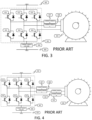
- FIG. 3 has only two current sensors 307 and 308 to monitor the current in the U and V motor phases.
- the DC link current is also measured at 306 because it is necessary to protect the W phase current against short-circuit currents that are not detected by sensors 307 and 308.
- the measurement from 306 is used solely to switch off the gate drives to the IBGT module 301, this action does not require isolation with respect to the gate driver circuit (not illustrated) for the IBGT module 301 and therefore the over-current protection circuit (not illustrated) can be referenced to the negative voltage bus 303: in other words using a current sensor 306 in the negative DC bus 303 is a cost-effective way of protecting the IGBT inverter bridge 201 against fault currents.
- This technique is applicable to a variant of FIG. 3 but in the interests of brevity it will not be described further.
- An AC permanent magnet servo that has interior magnets has a rotor flux vector that results from the sum of the flux vector from the magnets and a contribution form the stator current vector.
- safety standard ISO 10218 Safety requirements for industrial robots
- safety standard ISO 13849-1 Safety of machinerySafety-related parts of control systems
- a two-channel measurement of the rotor position can be performed using a two-channel encoder rated for functional safety at SIL2 or above. It is alternatively and equivalently possible to monitor two encoders of safety rating SIL1 to achieve safe position monitoring to SIL2.
- a two-channel current vector measurement can be implemented using a duplicated set of sensors, for example by elaborating the prior art of FIG. 3 to include a further, redundant, pair of phase current sensors 410 and 411 into the prior art of FIG. 4 .
- the main disadvantage of this implementation is that it requires inclusion of further current sensors with their attendant size and cost penalties.
- a two-channel current vector measurement can alternatively be implemented by making a measure of all three phase currents as shown in FIG. 2 and making use of the identity i u +i v +i w ⁇ 0; this is the method of SCHWESIG ( US Patent 7,737,652 ).
- the two current measurements are treated by the safety sub-system as a first channel and second channel is constructed from different pairs of phase currents.
- SCHWESIG teaches an implementation of SLT using the current measurement scheme of FIG. 2 in combination rotor position measurements and other items.
- SCHWESIG calculates the product of the current vector and flux vector, this is done twice as a part of a two-channel safety sub-system wherein a disparity between the two computed values of torque shut down the drive using safe torque-off (STO). If the calculated torque exceeds the threshold value, then the drive is shut down using STO.
- STO safe torque-off
- SCHWESIG measures current in the manner of FIG. 2 but it would be advantageous in respect of both size and cost to implement safely limited torque (SLT) in the manner of FIG. 3 , namely to do so with the minimum, cheapest set of current sensors that is already present to protect the IGBT module.
- SCHWESIG is adaptable to the current monitoring scheme of FIG. 1 by computing first and second torque values when the low side IGBTs are all ON simultaneously.
- BOYS Novel current sensor for PWM AC drives
- Proc. Inst. Elect. Eng. B, vol. 135, pp. 27-32, 1988 teaches a technique for inferring the three phase currents from the current returning to negative link 303 using just a single current sensor 306. Note that there is a variable delay between the current measurement and the subsequent application of voltage; for this reason and because of the two abnormal conditions described below this technique is seldom used for closed loop control.
- a torque-limiting safety circuit servo drive for AC permanent magnet motors including a three-phase inverter bridge, a first current sensor in series with a first motor phase, a second current sensor in series with a second motor phase, a third current sensor in series with the DC bus, and a drive control circuit that controls the six pulse-width modulated gate drive signals for the three-phase inverter bridge.
- the drive circuit has first and second safety channel STO inputs whereby either channel can shut down the three-phase inverter bridge.
- the drive circuit emits a signal set to represent the switching state of the three-phase inverter bridge.
- the drive circuit modifying the switching pattern of the PWM so as to ensure that the dwell times of pulse-width modulation are sufficiently long to allow a valid measurement of phase current using the bus current sensor.
- a first safety processor controls the first safety channel STO input of the drive control circuit, and a second safety processor controlling the second safety channel STO input of the drive control circuit.
- a torque-limiting safety circuit including a current vector re-constructor circuit wherein the current vector re-constructor circuit is supplied by the drive control circuit with a signal set representing the switching state of the three-phase inverter bridge, the current vector re-constructor circuit is further supplied with a signal representing the DC link current from the third current sensor, the current vector re-constructor constructs and second redundant estimated current vector, the current vector re-constructor circuit emits a signal set representing the estimated current vector and an error indication that confirms that the current vector estimate is valid.
- the first safety processor is supplied with the first phase current measurement and the second phase current measurement, wherein the first safety processor computes the motor torque and shuts down the three-phase inverter bridge using the first safety channel STO input of the drive control circuit when the motor exceeds a prescribed limit value.
- the second safety processor is supplied with the redundant estimated current vector and its related error indication, wherein the second safety processor computes the motor torque and shuts down the three-phase inverter bridge using the second safety channel STO input of the drive control circuit when the motor torque exceeds the prescribed limit value.
- a torque-limiting safety circuit is further provided including a rotor position sensor sub-system that emits two independent measurements of position wherein the first safety processor is further supplied with a first measurement of rotor angle whereby, in combination with its respective computed current vector, it computes a signed value of motor torque and shuts down the three-phase inverter bridge using the first safety channel STO input of the drive control circuit when the motor torque exceeds either a prescribed positive limit value or a prescribed negative limit value.
- the second safety processor is further supplied with a second measurement of rotor angle whereby, in combination with its respective computed current vector, it computes a signed value of motor torque and shuts down the three-phase inverter bridge using the second safety channel STO input of the drive control circuit when the motor torque exceeds either the prescribed positive limit value or the prescribed negative limit value.
- a torque-limiting safety circuit including a first current vector calculator and error detector circuit and a first current vector calculator and error detector circuit wherein a first current vector calculator and error detector circuit monitors the signal from the first phase current sensor, the signal from the second phase current sensor, the signal from the third current sensor in series with the DC bus.
- the signal set represents the switching state of the three-phase inverter bridge and thereby computes the current vector which it supplies as a signal set to the first safety processor.
- the first current vector calculator compares the signal from the third current sensor in series with the DC bus against the first or second phase current sensor as guided by the signal set representing switching state of the three-phase inverter bridge and by this means supplies a fault signal to the first safety processor denoting a discrepancy in the current measurement, thereby causing the first safety processor to shut down the drive using the first safety channel STO input.
- a second current vector calculator and error detector circuit monitors the signal from the first phase current sensor, the signal from the second phase current sensor, the signal from the third current sensor in series with the DC bus, the signal set representing the switching state of the three-phase inverter bridge and thereby computes the current vector which it supplies as a signal set to the second safety processor.
- the second current vector calculator compares the signal from the third current sensor in series with the DC bus against the first or second phase current sensor as guided by the signal set representing switching state of the three-phase inverter bridge and by this means supplies a fault signal to the second safety processor denoting a discrepancy in the current measurement, thereby causing the second safety processor to shut down the drive using the second safety channel STO input.
- the first safety processor is supplied with the first phase current measurement from the first current vector calculator, wherein the first safety processor computes the motor torque and shuts down the three-phase inverter bridge using the first safety channel STO input of the drive control circuit when the motor exceeds a prescribed limit value.
- the second safety processor is supplied with the second phase current measurement from the second current vector calculator, wherein the second safety processor computes the motor torque and shuts down the three-phase inverter bridge using the first safety channel STO input of the drive control circuit when the motor torque exceeds the prescribed limit value.
- a torque-limiting safety circuit is further provided including a rotor position sensor sub-system that emits two independent measurements of position wherein the first safety processor is further supplied with a first measurement of rotor angle whereby, in combination with its respective computed current vector, it computes a signed value of motor torque and shuts down the three-phase inverter bridge using the first safety channel STO input of the drive control circuit when the motor torque exceeds either a prescribed positive limit value or a prescribed negative limit value.
- the second safety processor is further supplied with a second measurement of rotor angle whereby, in combination with its respective computed current vector, it computes a signed value of motor torque and shuts down the three-phase inverter bridge using the second safety channel STO input of the drive control circuit when the motor torque exceeds either the prescribed positive limit value or the prescribed negative limit value.
- This invention makes a two-channel measurement of the current vector using the arrangement of current sensors in FIG. 3 .
- the first safety channel will be termed safety channel A and the second safety channel will be termed safety channel B.
- the safety sub-system uses the phase current measurements from sensors 307 and 308 to form the current vector for safety channel A using the well-known Clarke transformation from LEONHARD equation (10.4 a) in combination with Kirchoff's current law identity i u +i v +i w ⁇ 0 as shown in FIG. 5 .
- the current vector for safety channel B is derived from the bus current sensor 306 but here the measurements of the phase currents are discontinuous and are multiplexed through sensor 306 by the inverter bridge 301.
- This uses the technique of BOYS. For example when IGBTs 321, 332 and 333 are all ON and the remaining IGBTs 322, 323 and 331 are all OFF then the current in sensor 306 is the U phase current with positive polarity.
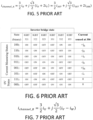
- the eight possible states of inverter bridge 301 are shown in FIG.
- states 000 2 and 111 2 namely all low side IGBTs are ON and all high-side IGBTs are ON respectively, apply no net voltage between the motor phases, these two states are therefore termed zero states and the remaining six states are termed active states.
- inverter bridge 301 will dwell twice at each of the states shown in FIG. 6 during a PWM cycle.
- the states are represented as binary numbers. For example, inverter bridge 301 will start at zero state 000 2 and then switch to either 001 2 or 010 2 or 100 2 and then to 011 2 or 110 2 or 101 2 and then to zero state 111 2 , in the second half of the cycle inverter bridge 301 switches to 011 2 or 110 2 or 101 2 and then 001 2 or 010 2 or 100 2 before returning to the initial zero state 000 2 . Regardless of the exact sequence of states it will be seen that the inverter bridge 301 will dwell at each of the eight states during a PWM cycle and therefore that a measurement of each of the three phase currents is available twice per switching cycle.
- the safety sub-system creates the current vector measurement for safety channel B using the phase current measurements according to the table of FIG. 6 using the formula of FIG. 7 as derived from LEONHARD page 151.
- the current vector measurement for safety channel B requires sampling and storing in a respective memory or logic register to be performed for each phase current measurement as they become available through the states of FIG. 6 so that the second measurement of the current vector can be re-constructed from these sequential measurements of the phase currents.
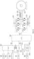
- FIG. 8 The elements of the safety sub-system that are required to implement SLT according to the first embodiment are depicted in FIG. 8 .
- 806-X corresponds to the input section of the current sensor 806
- 806-Y corresponds to the output section of the same sensor.
- the same input-output nomenclature is applied to current sensors 807 and 808.
- the current vector re-constructor circuit 849 is supplied with two input signals; the bus current signal from sensor 806 and a set of signals 846 that represent the state of the inverter bridge 801.
- the set of signals 851 that controls the IGBT bridge 801 can also serve as set of signals 846 that represent the state of the inverter bridge 801.
- the current vector re-constructor circuit 849 uses the formula of FIG. 7 and the relationships of FIG. 6 to create a pair of signals 850 that represents the current vector measurement for safety channel B and a signal 858 that indicates that the re-constructed current vector is valid.
- the current vector re-constructor circuit 849 uses sampling and storing, i.e. sample and hold action but implemented using digital circuitry, for each phase current measurement as they become available through the states of FIG. 6 .
- Element 844 implements the drive control circuit, this includes commutation, current loop closure, PWM generation and a switching power supply for the control circuit however FIG. 8 does not further illustrate these elements in order to present a clear view of the distinctive aspects of the invention.
- a safety processor 842 and 843 for each of the two safety channels A and B.
- the calculation of the motor torque requires each safety processor 842, 843 to rotate the current vector measurement into the frame of reference of the rotor as per LEONHARD equation (14.4) and for this reason each safety processor 842, 843 is also supplied with an independent measurement 840 and 841of the rotor position.
- Signals 840 and 841 are equivalently provided either from two, independent position sensors or alternatively from a safe position sensor having two independent outputs; in both cases the position sensor is aligned with the rotor flux vector during manufacture. There is also cross-checking between the safety processors 842 and 843 using intercommunication signal set 848.
- the cross-checking compares the position measurements 840 and 841 for the two channels and also compares the computed torque values for the two channels; a discrepancy beyond a prescribed limit is considered to be a fault and the STO signals 845 and 847 will be de-energized thereby shutting down the drive 844.
- the cross-checking also compares the computed torque values for the two channels and again a discrepancy beyond a prescribed limit is considered to be a fault and the STO signals 845 and 847 will be de-energized thereby shutting down the drive 844.
- the channel A safety processor 842 receives data from the current sensors 807 and 808 and the channel A rotor position measurement 840. It can optionally, in order to achieve greater diagnostic coverage, also receive data from the B channel's re-constructed current vector 850 and valid signal 858.
- the channel A safety processor 842 has an output 845, labelled STO_A, that can shut-down the PWM via the drive control circuit 844.
- the channel B safety processor 843 receives the channel B re-constructed current vector and the channel B rotor position measurement 841. It can optionally, for greater diagnostic coverage, also receive data from the channel A current sensors 807 and 808.
- the channel B safety processor 843 has an output 847, labelled STO_B, that can shut-down the PWM via the drive control circuit 844.
- One practical realization of the current vector re-constructor circuit 849 would be as a microcontroller, an example of suitable microcontroller is the STM32F031K6T7 which has 16kB of flash memory, 4k bytes of SRAM, a built-in 48MHz clock generator, serial ports and a 12-bit ADC: such a device can implement the re-constructor 849 as a single chip for only $1.
- An FPGA realization of the current vector re-constructor circuit 849 is alternatively possible and might be preferred - especially where it can be combined with an FPGA implementation of the drive control circuit 844.
- Safety standards such as IEC 62061 require that the two safety channels and drive control circuit 844 are separated by protective barriers so that the failure of one these three sub-circuits will not compromise functional safety, that is at least one of the safety channels will remain operational.
- the protective barriers are not illustrated in FIG. 8 but the protective barriers will be present in the pathway of signals 845, 847, 848, 849 and also 850 and 858 where these signals reach the channel A safety processor 842.
- the protective barriers can be implemented as impedances, opto-isolators, digital isolators and even as moat of unused gates within a logic device. Therefore the implementation of FIG. 8 can be varied to combine say the current re-constructor 849 with the channel B safety processor 843, and/or to combine the channel A safety processor 842 with the drive circuit in an FPGA.
- the current measurements derived from sensor 806-X using the relationships of FIG. 6 are not simultaneous, thus when a measurement of say the U phase current is made it will be stale by the time that the measurement of the V phase current is made.
- This combination of fresh and stale current measurements in the current vector re-constructor circuit 849 will distort the estimate 850 of the current vector used by safety channel B and consequently when the safety sub-system monitors the difference between the current vectors of the A and B channels it will be necessary to accommodate this distortion as an expected discrepancy, thereby limiting the smallest torque threshold that can be reliably detected.
- a reduction in the distortion can be obtained by using the two most recent phase current measurements to reconstruct the third current using by making use of the identity i u +i v +i w ⁇ 0 but some distortion of safety channel B current vector remains.
- the requirement for a two-channel measurement in a 1oo2 safety system is fulfilled in the first preferred embodiment using a duplicate set of independent measurements.
- a safety system that fails to an inoperative, safe state, to interpret the requirement for two channels not as two, duplicate sets of measurements but rather as a first set of a measurements in combination with a second set of measurements that, although not usable in their own right, independently indicate the validity of the first measurements.
- This latter approach is used in the second preferred embodiment of this invention as shown in FIG. 9 .
- the second preferred embodiment eliminates the problem of distortion in the reconstructed current vector 850 of FIG. 8 . Rather than assemble a second current vector to compare with the first current vector, the second preferred embodiment instead compares the phase currents from the two sources whenever the data from sensor 906-Y is fresh and therefore accurate.
- the measurement from the U phase current sensor at 907-Y can be compared with the measurement from bus current sensor at 906-Y in states 100 2 and 011 2 . In the latter state the current sensed current from 906-Y must be inverted.
- the measurement from the V phase current sensor at 908-Y can be compared with the measurement from bus current sensor at 906-Y in states 010 2 and 101 2 . In the latter state the current sensed current from 906-Y must be inverted.
- SLT in FIG. 9 retains the same general structure and many of the elements of FIG. 8 .
- the reference numerals of FIG. 9 are consistent with those of FIG. 8 , thus for example the drive control circuit in 944 in FIG. 9 is the same as the control circuit in 844 in FIG. 8 .
- the description of FIG. 9 will therefore concentrate only on those elements that are different from FIG. 8 .
- Safety channel A is equipped with a current vector calculator 952 whose inputs are the inverter bridge state 946, a measurement of the DC link current 906-Y, a measurement of the U phase current 907-Y and a measurement of the V phase current 908-Y.
- the current vector calculator 952 uses input signals 907-Y and the 908-Y to compute the stator current vector output 954.
- inverter bridge states 000 2 and 111 2 - namely the zero states - no further action is taken but for all other states the instantaneous value of the bus current signal from sensor 906-Y is checked by the current vector calculator 952 against the corresponding instantaneous value of phase current according to FIG. 6 .
- the current vector calculator 952 declares a fault at output 956 when the two estimates of phase currents diverge by more than a prescribed limit.
- Safety channel B is likewise is equipped with a current vector calculator 953 whose inputs, outputs and operation are the same as the channel A current vector calculator 952.
- Each safety processor 942 and 943 computes the motor torque from the phase current measurements 954 and 955 in combination with the respective position measurement 940 and 941 for the respective safety channel. Note that this calculation can take place at any time, it will be valid regardless of switching state of the inverter bridge 901.
- Each safety processor 942 and 943 is also notified of errors in the current measurement via signals 956 and 957. If either safety processor 942 and 943 detects a discrepancy from the other processor or that the torque has exceeded the prescribed threshold of the SLT safety function, or that there has been an error in the current measurement, then either safety processor 942 and 943 can shut-down the output drive control circuit 944 using their respective STO control signals 945 and 947.
- Both the first and second embodiments combine a two-channel measurement of rotor position with a two-channel measurement of the current vector to obtain a two-channel measurement of torque.
- the torque measurement can be a positive torque or a negative torque and this has the advantage that the computed torque can be compared against independent positive and negative limit values in order to implement SLT. This is of practical value; consider a machine where a gravity loaded axis is monitored using SLT to avoid crushing an operator's limb, in this machine the downward direction torque threshold would be low whereas the upward torque threshold must be higher to allow the machine to retract in the vertical direction.
- the third preferred embodiment the same as the first preferred embodiment as illustrated in FIG. 8 but with the removal of safety channel A rotor position measurement 840 and safety channel B rotor position measurement 841; it is so similar to FIG. 8 that no further diagram is given.
- Each safety processor 842 and 843 rather than computing torque, instead computes the magnitude of the channel A current vector and the magnitude of the channel B current vector and compares the two magnitudes against the SLT limit values.
- the motor torque is proportional to the sine of the angle between the rotor flux vector and the current vector, the worst case is that the angle is ninety degrees and that the sine is unity thereby yielding the maximum torque. For all other angles the resultant torque will be a lesser value and therefore simply using the magnitude of the current vector will over-estimate the motor current; an over-estimate will trigger SLT at too low a torque value but note that this is a safe condition.
- the fourth preferred embodiment is the same as the second preferred embodiment as illustrated in FIG. 9 but with the removal of safety channel A rotor position measurement 940 and safety channel B rotor position measurement 941; it is so similar to FIG. 9 that no further diagram is given.
- Each safety processor 942 and 943 rather than computing torque, instead computes the magnitude of the channel A current vector and the magnitude of the channel B current vector and compares the two magnitudes against the SLT limit values.
- all four preferred embodiments use the measurement of the bus current in the various inverter bridge states either to create a measurement of the current vector for the channel B or else to confirm that the measurement of the current vector from two sensors in series with the motor phases are correct.
- All four preferred embodiments use a set of current sensors that is already present in many servo drive designs. A map of preferred embodiment against feature is provided in FIG. 10 .
- All four preferred embodiments require deducing the phase current from the bus current and the inverter bridge state. There are two abnormal conditions wherein a timely measurement of each phase current will not be available at a rate of twice per PWM switching cycle from the bus current sensor 306 or 806 or 906.
- the first abnormal condition is when the servo drive is on but is applying no net voltage, the inverter bridge 301 will cycle between the zero states 000 2 and 111 2 wherein it can be seen from FIG. 6 that no current measurements are available from sensor 306.
- a variant of this first abnormal condition is when the net output voltage is so low that, although the inverter sequences through all states, the dwell time in the states other than 000 2 and 111 2 is too short to allow a useful measurement of the respective phase current.
- the dwell time must be long enough to allow transient effects, such as the impulse current flowing into stray capacitances and diode recovery currents, to decay. Therefore a practical minimum dwell time is on the order of 5 ⁇ s and in the first abnormal condition this may not be fulfilled.
- the drive circuit 844 or 944 is algorithmically altered to artificially prolong the dwell times that are present or to insert current measuring states of adequate dwell times that would otherwise be absent when the required dwell times have not occurred naturally through closed-loop control.
- the term 'prolongation' will cover both cases. This prolongation can be performed entirely in logic gates or by using software.
- the second abnormal condition occurs at high rotary speeds when the servo drive has insufficient bus voltage to fully control the phase currents; under these circumstances the PWM saturates and the drive is in what is called quasi-squarewave operation, the inverter bridge 301 will progress through a sequence such as 101 2 ⁇ 100 2 ⁇ 110 2 ⁇ 010 2 ⁇ 011 2 ⁇ 001 2 and then repeat but at the fundamental frequency of the current rather than at the PWM switching frequency, e.g. 100Hz rather than 16kHz.
- a measurement of current is available for all three currents but at a rate much less than twice the PWM switching frequency. However this rate of 100Hz is frequent enough to check the two current measurements in the case of the second and fourth embodiments, whereas the first and third embodiments will require artificial dwell times to be inserted. In summary all four embodiments can operate despite this second abnormal condition.
- the drive circuit 844 is responsible for ensuring that the dwell times of the IGBT inverter state 846 are long enough to allow valid current measurements to be made.
- the current vector re-constructor circuit 849 will indicate 858 when the re-constructed current vector 850 is invalid as a result of insufficiently long dwell times 846 and thereby cause safety processor 842 and optionally safety processor 843 to put the drive in STO using signals STO_B 847 and optionally STO_A 845.
- This division of responsibilities allows the drive control circuit 844 to be wholly non-safe, that is designed and maintained without the constraints of safe processes, whereas the current re-constructor circuit 949 is part of the safety system.
- the drive circuit 944 is responsible for ensuring that the dwell times of the IGBT inverter state 946 are long enough to allow valid current measurements to be made.
- the current vector calculator and fault detector circuits 952 and 953 will respectively indicate 956 and 957 when either re-constructed current vector 954 or 955 is invalid as a result of insufficiently long dwell times 946 and thereby cause either or both safety processors 942 and 943 to put the drive in STO using signals STO_A 945 and/or STO_B 947.
- This division of responsibilities allows the drive control circuit 944 to be wholly non-safe, that is designed and maintained without the constraints of safe processes, whereas the current vector calculator circuits 952 and 953 are part of the safety system.
- the two safety processors 842/942 and 843/943 are typically implemented as microcontrollers. However the term 'safety processor' is technologically neutral and could alternatively be implemented using FPGA gates or as FPGA soft processors.
- the two safety processors 842/942 and 843/943 could be combined into a dual lock-step safety processor or into a triple mode redundant safety processor without changing the essential concept of the invention.
- the current re-constructor 849 and B channel safety processor 843 could be combined into a single device.
- the drive control circuit 844 could be combined into a single device with either safety processor for safety channel A 842 or the safety processor for safety channel B 843. Implementations of FIG. 8 using one or more FPGAs are also possible.
Landscapes
- Engineering & Computer Science (AREA)
- Power Engineering (AREA)
- Control Of Ac Motors In General (AREA)
- Inverter Devices (AREA)
Claims (10)
- Servoantrieb mit drehmomentbegrenzender Sicherheitsschaltung für einen Wechselstrom-Permanentmagnetmotor, umfassend:eine dreiphasige Wechselrichterbrücke (801), die von einem DC-Bus gespeist wird;einen ersten Stromsensor (807), der Strom in einer ersten Motorphase erfasst;einen zweiten Stromsensor (808), der Strom in einer zweiten Motorphase erfasst;einen dritten Stromsensor, der Strom im DC-Bus erfasst;eine Antriebssteuerungsschaltung (844), die pulsbreitenmodulierte Gate-Treibersignale an die dreiphasige Wechselrichterbrücke (801) liefert, wobei die Antriebssteuerungsschaltung (844) einen ersten Sicherheitskanal-Safe-Torque-Off-Eingang und einen zweiten Sicherheitskanal-Safe-Torque-Off-Eingang aufweist, wobei die Antriebssteuerungsschaltung (844) angepasst ist, um einen Signalsatz auszugeben, der einen Schaltzustand der dreiphasigen Wechselrichterbrücke (801) darstellt, um ein pulsbreitenmoduliertes Schaltmuster zu ändern;einen ersten Sicherheitsprozessor, der den ersten Sicherheitskanal-Safe-Torque-Off-Eingang der Antriebssteuerungsschaltung (844) steuert;einen zweiten Sicherheitsprozessor, der den zweiten Sicherheitskanal-Safe-Torque-Off-Eingang der Antriebssteuerungsschaltung (844) steuert;einen ersten Stromvektorrechner und Fehlerdetektor, der so konfiguriert ist, dass er auf der Grundlage eines Signals vom dritten Stromsensor und des Signalsatzes, der einen Schaltzustand der dreiphasigen Wechselrichterbrücke (801) darstellt, eine Diskrepanz erfasst, wobei die Signale mit den ersten und zweiten Stromsensorsignalen verglichen werden, und auf der Grundlage der Diskrepanz ein Fehlersignal an den ersten Sicherheitsprozessor liefert; undeinen zweiten Stromvektorrechner und Fehlerdetektor, der so konfiguriert ist, dass er auf der Grundlage eines Signals vom dritten Stromsensor und des Signalsatzes, der einen Schaltzustand der dreiphasigen Wechselrichterbrücke (801) darstellt, eine Diskrepanz erfasst, wobei die Signale mit den ersten und zweiten Stromsensorsignalen verglichen werden, und auf der Grundlage dieser Diskrepanz ein Fehlersignal an den zweiten Sicherheitsprozessor liefert;wobei die Antriebssteuerungsschaltung (844) angepasst ist, um die dreiphasige Wechselrichterbrücke (801) als Reaktion auf eine Eingabe von entweder dem ersten Sicherheitsprozessor (842) oder dem zweiten Sicherheitsprozessor (847) abzuschalten.
- Servoantrieb mit drehmomentbegrenzender Sicherheitsschaltung nach Anspruch 1, wobei die Antriebsschaltung und der Sicherheitsprozessor eine Einzelvorrichtung sind.
- Servoantrieb mit drehmomentbegrenzender Sicherheitsschaltung nach Anspruch 1, wobei die Antriebssteuerungsschaltung (844) so konfiguriert ist, dass sie das Schaltmuster der Pulsweitenmodulation ändert und dadurch eine lange Verweilzeit der Pulsweitenmodulation bereitstellt, um eine genaue Messung des Phasenstroms unter Verwendung des dritten Stromsensors durchzuführen.
- Servoantrieb mit drehmomentbegrenzender Sicherheitsschaltung nach Anspruch 1, der weiter ein Rotorpositionssensor-Teilsystem umfasst, das so konfiguriert ist, dass es eine erste Rotorpositionsmessung an den ersten Sicherheitsprozessor und eine zweite Rotorpositionsmessung an den zweiten Sicherheitsprozessor (842) liefert, wobei die erste Rotorpositionsmessung unabhängig von der zweiten Rotorpositionsmessung ist.
- Servoantrieb mit drehmomentbegrenzender Sicherheitsschaltung nach Anspruch 1, wobei die Antriebssteuerungsschaltung (844) so konfiguriert ist, dass sie einen Signalsatz (846, 847) ausgibt, der einen Schaltzustand der dreiphasigen Wechselrichterbrücke (801) darstellt.
- Servoantrieb mit drehmomentbegrenzender Sicherheitsschaltung nach Anspruch 3, der weiter eine Stromvektor-Rekonstruktionsschaltung (849) umfasst, die so konfiguriert ist, dass sie einen geschätzten Stromvektor auf der Grundlage des Signalsatzes (859, 858), der den Schaltzustand der dreiphasigen Wechselrichterbrücke (801) darstellt, und eines Signalsatzes, der einen DC-Zwischenkreisstrom von dem dritten Stromsensor darstellt, konstruiert.
- Servoantrieb mit drehmomentbegrenzender Sicherheitsschaltung nach Anspruch 6, wobei die Stromvektor-Rekonstruktionsschaltung (849) so konfiguriert ist, dass sie einen Signalsatz ausgibt, der den geschätzten Stromvektor und eine Fehleranzeige darstellt, wobei die Fehleranzeige die Genauigkeit der Stromvektorschätzung bestätigt.
- Servoantrieb mit drehmomentbegrenzender Sicherheitsschaltung nach Anspruch 6, wobei Stromvektorverzerrung unter Verwendung der beiden letzten Phasenstrommessungen reduziert wird, um Strom aus dem dritten Stromsensor unter Verwendung einer Identität iu + iv + iw = 0 zu rekonstruieren.
- Servoantrieb mit drehmomentbegrenzender Sicherheitsschaltung nach Anspruch 6, wobei der Stromvektor-Rekonstruktor und der zweite Sicherheitsprozessor (843) in einer einzigen physikalischen Vorrichtung kombiniert sind.
- Servoantrieb mit drehmomentbegrenzender Sicherheitsschaltung nach Anspruch 6, wobei der erste Sicherheitsprozessor (842) und die Antriebsschaltung in einem feldprogrammierbaren Gate-Array kombiniert sind.
Applications Claiming Priority (2)
| Application Number | Priority Date | Filing Date | Title |
|---|---|---|---|
| US201962875320P | 2019-07-17 | 2019-07-17 | |
| PCT/US2020/041637 WO2021011389A1 (en) | 2019-07-17 | 2020-07-10 | Method and apparatus for the safe limitation of motor torque in a three-phase drive |
Publications (3)
| Publication Number | Publication Date |
|---|---|
| EP4000175A1 EP4000175A1 (de) | 2022-05-25 |
| EP4000175B1 true EP4000175B1 (de) | 2025-05-21 |
| EP4000175C0 EP4000175C0 (de) | 2025-05-21 |
Family
ID=71895246
Family Applications (1)
| Application Number | Title | Priority Date | Filing Date |
|---|---|---|---|
| EP20750077.8A Active EP4000175B1 (de) | 2019-07-17 | 2020-07-10 | Verfahren und vorrichtung zur sicheren begrenzung des motordrehmoments in einem drei phasen antrieb |
Country Status (3)
| Country | Link |
|---|---|
| US (1) | US11387767B2 (de) |
| EP (1) | EP4000175B1 (de) |
| WO (1) | WO2021011389A1 (de) |
Families Citing this family (2)
| Publication number | Priority date | Publication date | Assignee | Title |
|---|---|---|---|---|
| CN114325380B (zh) * | 2021-11-25 | 2022-12-27 | 合肥工业大学 | 一种永磁同步电机驱动系统故障诊断方法 |
| CN114499285B (zh) * | 2022-03-30 | 2024-02-13 | 美的集团(上海)有限公司 | 安全转矩关断功能电路和控制方法 |
Family Cites Families (4)
| Publication number | Priority date | Publication date | Assignee | Title |
|---|---|---|---|---|
| US5896257A (en) | 1997-10-17 | 1999-04-20 | Allen-Bradley Company, Llc | Two sensor for over-current protection and current sensing configuration motor control |
| DE102006042038B3 (de) | 2006-09-07 | 2008-02-07 | Siemens Ag | Verfahren und Vorrichtung zur sicheren Drehmomentbegrenzung |
| AT517400B1 (de) * | 2015-06-25 | 2017-06-15 | Bernecker + Rainer Industrie-Elektronik Ges M B H | Verfahren und Vorrichtung zur Ermittlung einer physikalischen Größe einer Mehrphasen-Synchronmaschine |
| JP2017051070A (ja) * | 2015-09-04 | 2017-03-09 | ファナック株式会社 | Dcリンク電流検出機能を有するモータ駆動装置 |
-
2020
- 2020-07-10 EP EP20750077.8A patent/EP4000175B1/de active Active
- 2020-07-10 WO PCT/US2020/041637 patent/WO2021011389A1/en not_active Ceased
- 2020-07-10 US US16/926,244 patent/US11387767B2/en active Active
Also Published As
| Publication number | Publication date |
|---|---|
| EP4000175A1 (de) | 2022-05-25 |
| US20210021226A1 (en) | 2021-01-21 |
| WO2021011389A1 (en) | 2021-01-21 |
| US11387767B2 (en) | 2022-07-12 |
| EP4000175C0 (de) | 2025-05-21 |
Similar Documents
| Publication | Publication Date | Title |
|---|---|---|
| KR101236083B1 (ko) | 리던던트 비상 제동 회로를 가진 산업용 로봇 | |
| JP4589436B2 (ja) | 安全関連の装置を安全な状態に設定するための切り換え装置 | |
| US9793849B2 (en) | Inverter apparatus for polyphase AC motor drive | |
| EP4000175B1 (de) | Verfahren und vorrichtung zur sicheren begrenzung des motordrehmoments in einem drei phasen antrieb | |
| US20190252970A1 (en) | Power conversion apparatus and logic circuit | |
| CN108189672B (zh) | 一种基于功能安全的电动汽车集成控制器 | |
| US6495986B2 (en) | Safe speed monitoring for sensor-free three-phase drives | |
| GB2511564A (en) | Fail safe circuit | |
| US10071762B2 (en) | Detection and mitigation of inverter errors in steering system motors | |
| US6999326B2 (en) | Drive controller for a self-commutated converter | |
| Li et al. | A fast diagnosis strategy for inverter open-circuit faults based on the current path of brushless DC motors | |
| JP2013500697A (ja) | 電気駆動装置の運動変量のフェイルセーフ監視方法および装置 | |
| US7529111B2 (en) | Drive controller for a self-commutated converter | |
| KR101384783B1 (ko) | 극전압 측정 기반의 인버터 개방오류 검출장치 | |
| US9941815B2 (en) | Power conversion apparatus with overcurrent simulating circuit | |
| KR101916046B1 (ko) | 전압 센서 고장 감지 방법 | |
| Klimkowski et al. | Neural network approach for stator current sensor fault detection and isolation for vector controlled induction motor drive | |
| JP5888941B2 (ja) | 保護継電器 | |
| Tao et al. | A diagnosis method for IGBT and current sensor faults of two-level inverter used in traction systems | |
| US6909255B2 (en) | Drive controller for a self-commutated converter | |
| WO2022264314A1 (ja) | モータの絶縁抵抗値を計算するモータ駆動装置 | |
| KR20190007444A (ko) | 안전 센서를 모니터링하기 위한 모니터링 장치 및 안전 센서를 모니터링하기 위한 방법 | |
| US20180159448A1 (en) | Method and device for checking an electrical value of an electric machine | |
| US11784606B2 (en) | Method and device for a failsafe rotational speed monitoring process | |
| Errabelli et al. | A fault tolerant control and power electronic for a permanent magnet synchronous motor drive |
Legal Events
| Date | Code | Title | Description |
|---|---|---|---|
| STAA | Information on the status of an ep patent application or granted ep patent |
Free format text: STATUS: UNKNOWN |
|
| STAA | Information on the status of an ep patent application or granted ep patent |
Free format text: STATUS: THE INTERNATIONAL PUBLICATION HAS BEEN MADE |
|
| PUAI | Public reference made under article 153(3) epc to a published international application that has entered the european phase |
Free format text: ORIGINAL CODE: 0009012 |
|
| STAA | Information on the status of an ep patent application or granted ep patent |
Free format text: STATUS: REQUEST FOR EXAMINATION WAS MADE |
|
| 17P | Request for examination filed |
Effective date: 20220202 |
|
| AK | Designated contracting states |
Kind code of ref document: A1 Designated state(s): AL AT BE BG CH CY CZ DE DK EE ES FI FR GB GR HR HU IE IS IT LI LT LU LV MC MK MT NL NO PL PT RO RS SE SI SK SM TR |
|
| DAV | Request for validation of the european patent (deleted) | ||
| DAX | Request for extension of the european patent (deleted) | ||
| P01 | Opt-out of the competence of the unified patent court (upc) registered |
Effective date: 20230504 |
|
| STAA | Information on the status of an ep patent application or granted ep patent |
Free format text: STATUS: EXAMINATION IS IN PROGRESS |
|
| 17Q | First examination report despatched |
Effective date: 20230704 |
|
| GRAP | Despatch of communication of intention to grant a patent |
Free format text: ORIGINAL CODE: EPIDOSNIGR1 |
|
| STAA | Information on the status of an ep patent application or granted ep patent |
Free format text: STATUS: GRANT OF PATENT IS INTENDED |
|
| INTG | Intention to grant announced |
Effective date: 20241217 |
|
| GRAS | Grant fee paid |
Free format text: ORIGINAL CODE: EPIDOSNIGR3 |
|
| GRAA | (expected) grant |
Free format text: ORIGINAL CODE: 0009210 |
|
| STAA | Information on the status of an ep patent application or granted ep patent |
Free format text: STATUS: THE PATENT HAS BEEN GRANTED |
|
| AK | Designated contracting states |
Kind code of ref document: B1 Designated state(s): AL AT BE BG CH CY CZ DE DK EE ES FI FR GB GR HR HU IE IS IT LI LT LU LV MC MK MT NL NO PL PT RO RS SE SI SK SM TR |
|
| REG | Reference to a national code |
Ref country code: GB Ref legal event code: FG4D |
|
| REG | Reference to a national code |
Ref country code: CH Ref legal event code: EP |
|
| REG | Reference to a national code |
Ref country code: DE Ref legal event code: R096 Ref document number: 602020051621 Country of ref document: DE |
|
| REG | Reference to a national code |
Ref country code: IE Ref legal event code: FG4D |
|
| U01 | Request for unitary effect filed |
Effective date: 20250620 |
|
| U07 | Unitary effect registered |
Designated state(s): AT BE BG DE DK EE FI FR IT LT LU LV MT NL PT RO SE SI Effective date: 20250701 |
|
| P04 | Withdrawal of opt-out of the competence of the unified patent court (upc) registered |
Free format text: CASE NUMBER: APP_30996/2025 Effective date: 20250627 |
|
| U20 | Renewal fee for the european patent with unitary effect paid |
Year of fee payment: 6 Effective date: 20250731 |
|
| PG25 | Lapsed in a contracting state [announced via postgrant information from national office to epo] |
Ref country code: ES Free format text: LAPSE BECAUSE OF FAILURE TO SUBMIT A TRANSLATION OF THE DESCRIPTION OR TO PAY THE FEE WITHIN THE PRESCRIBED TIME-LIMIT Effective date: 20250521 |
|
| PG25 | Lapsed in a contracting state [announced via postgrant information from national office to epo] |
Ref country code: GR Free format text: LAPSE BECAUSE OF FAILURE TO SUBMIT A TRANSLATION OF THE DESCRIPTION OR TO PAY THE FEE WITHIN THE PRESCRIBED TIME-LIMIT Effective date: 20250822 Ref country code: NO Free format text: LAPSE BECAUSE OF FAILURE TO SUBMIT A TRANSLATION OF THE DESCRIPTION OR TO PAY THE FEE WITHIN THE PRESCRIBED TIME-LIMIT Effective date: 20250821 |
|
| PG25 | Lapsed in a contracting state [announced via postgrant information from national office to epo] |
Ref country code: PL Free format text: LAPSE BECAUSE OF FAILURE TO SUBMIT A TRANSLATION OF THE DESCRIPTION OR TO PAY THE FEE WITHIN THE PRESCRIBED TIME-LIMIT Effective date: 20250521 |
|
| PG25 | Lapsed in a contracting state [announced via postgrant information from national office to epo] |
Ref country code: HR Free format text: LAPSE BECAUSE OF FAILURE TO SUBMIT A TRANSLATION OF THE DESCRIPTION OR TO PAY THE FEE WITHIN THE PRESCRIBED TIME-LIMIT Effective date: 20250521 |
|
| PG25 | Lapsed in a contracting state [announced via postgrant information from national office to epo] |
Ref country code: RS Free format text: LAPSE BECAUSE OF FAILURE TO SUBMIT A TRANSLATION OF THE DESCRIPTION OR TO PAY THE FEE WITHIN THE PRESCRIBED TIME-LIMIT Effective date: 20250821 |
|
| PG25 | Lapsed in a contracting state [announced via postgrant information from national office to epo] |
Ref country code: IS Free format text: LAPSE BECAUSE OF FAILURE TO SUBMIT A TRANSLATION OF THE DESCRIPTION OR TO PAY THE FEE WITHIN THE PRESCRIBED TIME-LIMIT Effective date: 20250921 |
|
| PG25 | Lapsed in a contracting state [announced via postgrant information from national office to epo] |
Ref country code: SM Free format text: LAPSE BECAUSE OF FAILURE TO SUBMIT A TRANSLATION OF THE DESCRIPTION OR TO PAY THE FEE WITHIN THE PRESCRIBED TIME-LIMIT Effective date: 20250521 |
|
| PG25 | Lapsed in a contracting state [announced via postgrant information from national office to epo] |
Ref country code: CZ Free format text: LAPSE BECAUSE OF FAILURE TO SUBMIT A TRANSLATION OF THE DESCRIPTION OR TO PAY THE FEE WITHIN THE PRESCRIBED TIME-LIMIT Effective date: 20250521 |
|
| PG25 | Lapsed in a contracting state [announced via postgrant information from national office to epo] |
Ref country code: SK Free format text: LAPSE BECAUSE OF FAILURE TO SUBMIT A TRANSLATION OF THE DESCRIPTION OR TO PAY THE FEE WITHIN THE PRESCRIBED TIME-LIMIT Effective date: 20250521 |
|
| REG | Reference to a national code |
Ref country code: CH Ref legal event code: H13 Free format text: ST27 STATUS EVENT CODE: U-0-0-H10-H13 (AS PROVIDED BY THE NATIONAL OFFICE) Effective date: 20260224 |
|
| PLBE | No opposition filed within time limit |
Free format text: ORIGINAL CODE: 0009261 |
|
| STAA | Information on the status of an ep patent application or granted ep patent |
Free format text: STATUS: NO OPPOSITION FILED WITHIN TIME LIMIT |
|
| REG | Reference to a national code |
Ref country code: CH Ref legal event code: L10 Free format text: ST27 STATUS EVENT CODE: U-0-0-L10-L00 (AS PROVIDED BY THE NATIONAL OFFICE) Effective date: 20260402 |
|
| PG25 | Lapsed in a contracting state [announced via postgrant information from national office to epo] |
Ref country code: CH Free format text: LAPSE BECAUSE OF NON-PAYMENT OF DUE FEES Effective date: 20250731 |
|
| 26N | No opposition filed |
Effective date: 20260224 |