EP4000152B1 - Gerät mit integrierter fehlerstromdetektion - Google Patents
Gerät mit integrierter fehlerstromdetektion Download PDFInfo
- Publication number
- EP4000152B1 EP4000152B1 EP20840080.4A EP20840080A EP4000152B1 EP 4000152 B1 EP4000152 B1 EP 4000152B1 EP 20840080 A EP20840080 A EP 20840080A EP 4000152 B1 EP4000152 B1 EP 4000152B1
- Authority
- EP
- European Patent Office
- Prior art keywords
- blender
- appliance
- detection circuit
- ground plane
- ground
- Prior art date
- Legal status (The legal status is an assumption and is not a legal conclusion. Google has not performed a legal analysis and makes no representation as to the accuracy of the status listed.)
- Active
Links
Images





Classifications
-
- G—PHYSICS
- G01—MEASURING; TESTING
- G01R—MEASURING ELECTRIC VARIABLES; MEASURING MAGNETIC VARIABLES
- G01R31/00—Arrangements for testing electric properties; Arrangements for locating electric faults; Arrangements for electrical testing characterised by what is being tested not provided for elsewhere
- G01R31/50—Testing of electric apparatus, lines, cables or components for short-circuits, continuity, leakage current or incorrect line connections
- G01R31/52—Testing for short-circuits, leakage current or ground faults
-
- H—ELECTRICITY
- H02—GENERATION; CONVERSION OR DISTRIBUTION OF ELECTRIC POWER
- H02H—EMERGENCY PROTECTIVE CIRCUIT ARRANGEMENTS
- H02H3/00—Emergency protective circuit arrangements for automatic disconnection directly responsive to an undesired change from normal electric working condition with or without subsequent reconnection ; integrated protection
- H02H3/16—Emergency protective circuit arrangements for automatic disconnection directly responsive to an undesired change from normal electric working condition with or without subsequent reconnection ; integrated protection responsive to fault current to earth, frame or mass
- H02H3/167—Emergency protective circuit arrangements for automatic disconnection directly responsive to an undesired change from normal electric working condition with or without subsequent reconnection ; integrated protection responsive to fault current to earth, frame or mass combined with other earth-fault protective arrangements
-
- H—ELECTRICITY
- H02—GENERATION; CONVERSION OR DISTRIBUTION OF ELECTRIC POWER
- H02H—EMERGENCY PROTECTIVE CIRCUIT ARRANGEMENTS
- H02H3/00—Emergency protective circuit arrangements for automatic disconnection directly responsive to an undesired change from normal electric working condition with or without subsequent reconnection ; integrated protection
- H02H3/26—Emergency protective circuit arrangements for automatic disconnection directly responsive to an undesired change from normal electric working condition with or without subsequent reconnection ; integrated protection responsive to difference between voltages or between currents; responsive to phase angle between voltages or between currents
- H02H3/32—Emergency protective circuit arrangements for automatic disconnection directly responsive to an undesired change from normal electric working condition with or without subsequent reconnection ; integrated protection responsive to difference between voltages or between currents; responsive to phase angle between voltages or between currents involving comparison of the voltage or current values at corresponding points in different conductors of a single system, e.g. of currents in go and return conductors
- H02H3/33—Emergency protective circuit arrangements for automatic disconnection directly responsive to an undesired change from normal electric working condition with or without subsequent reconnection ; integrated protection responsive to difference between voltages or between currents; responsive to phase angle between voltages or between currents involving comparison of the voltage or current values at corresponding points in different conductors of a single system, e.g. of currents in go and return conductors using summation current transformers
-
- A—HUMAN NECESSITIES
- A47—FURNITURE; DOMESTIC ARTICLES OR APPLIANCES; COFFEE MILLS; SPICE MILLS; SUCTION CLEANERS IN GENERAL
- A47J—KITCHEN EQUIPMENT; COFFEE MILLS; SPICE MILLS; APPARATUS FOR MAKING BEVERAGES
- A47J43/00—Implements for preparing or holding food, not provided for in other groups of this subclass
- A47J43/04—Machines for domestic use not covered elsewhere, e.g. for grinding, mixing, stirring, kneading, emulsifying, whipping or beating foodstuffs, e.g. power-driven
- A47J43/046—Machines for domestic use not covered elsewhere, e.g. for grinding, mixing, stirring, kneading, emulsifying, whipping or beating foodstuffs, e.g. power-driven with tools driven from the bottom side
Definitions
- This specification relates generally to appliances, and more particularly, to an appliance with integrated ground fault/current leak detection to at least partially disable the appliance in response to detection of food/liquids making contact with energized pins/terminals of the appliance.
- a "ground fault” is a conducting connection (whether intentional or accidental) between any electric conductor and any conducting material that is grounded or that may become grounded. Electricity always seeks out the easiest path to the ground, and in a ground fault, this can include electricity conducting through a person's body.
- GFCI ground-fault circuit interrupters
- a heated blender is one such example where there is need for an electrical connection from the base of the blender to the jar of the blender so that a heating element within the jar can be powered.
- the heating element can require a line voltage to be connected through the pins/terminals of the blender base and blender jar.
- GFCI can significantly decrease the chance of those line voltages from making contact with a user, but the availability of GFCI and associated costs raise non-trivial challenges.
- a positioning plate presses against a positioning switch on the coupling portion when the annular seat couples with the coupling portion, with the power supply terminal and a coupling section of the temperature sensor respectively extending into the terminal hole and the sensor hole for electrical connection with the control circuit board, allowing the control circuit board to control the motor and the heating tube.
- the invention provides an appliance as defined in claim 1.
- Optional/preferable features are set out in the dependent claims.
- a ground fault circuit interrupter disconnects a power source upon the detection of an undesired grounding (referred to herein as a GF event) of a power rail.
- GF event an undesired grounding
- Such devices are effective at reducing electric socks, but unfortunately are often unavailable and can provide a false sense of security.
- GFCIs require periodic testing and replacement, and can be rendered ineffective over time without warning if not tested regularly. Many GFCIs go untested for years on end.
- Some appliances feature power-cord based GF/leak detectors such as equipment leakage current interrupters (ELCIs).
- ELCIs equipment leakage current interrupters
- ELCIs and the like add considerable bulk and often require expensive components to implement.
- the result can be an abrupt shutting "OFF" of the device until the user initiate a reset or otherwise remedies the cause of the GF.
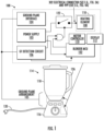
- a blender consistent with the present disclosure includes at least one ground plane, e.g., in the form of conductive material/sections, disposed on the blender and/or blender jar that act as an input to a GF detection circuit that is at least partially implemented within the base of the blender.
- conductive blender material such as a banana smoothie recipe
- This blender material may also be referred to herein as spillover conductive blender material.
- the pooling of conductive blender material can result in contact between "live" power pin(s) of the connector and the conductive blender material.
- the GF detection circuit utilizes the one or more ground planes to detect this condition, e.g., based on a measured current leak, and disable/de-energize the power pins to avoid potential electrical shocks.
- the GF detection circuit thus can transition the blender into a fault mode/operating state wherein the heating element and associated features/functions get disabled.
- Power to other components such as an associated microcontroller, blade motor controller, blade motor, can preferably remain uninterrupted during the fault mode, e.g., remains capable of being energized by a power supply.
- a blender consistent with the present disclosure provides numerous advantageous over other approaches, and particularly those approaches that require a GFCI receptacle to operate safely.
- faults get visually displayed, e.g., via a user interface of the blender, and can optionally present a mitigating action such as a prompt that states "FAULT DETECTED, HEAT FUNCTIONS DISABLED, CLEAN UNIT OR CONSULT MANUAL.”
- the fault may be visually displayed via one or more LEDs and/or audibly provided via an implemented speaker.
- the fault may also cause the blender to send a message, preferably via a wireless network connection, to a user's smart phone or other computing device.
- An "app" on the smart phone or computer device may then display the error condition and preferably suggest a mitigating action to clear the error condition. This advantageously allows a user to identify the fault has occurred and steps that can remedy the fault. Also, the blender can optionally remain functional/energized for other tasks such as blending/chopping that do not require the heating element.
- the GF detection circuits of the present disclosure can conform to various standards, e.g., UL-standards, that require fast response times, e.g., 5 ms or less, and that require maximum current thresholds, e.g., 5 mA.
- a blender consistent with the present disclosure can therefore provide GF detection without requiring a GFCI-enabled outlet or a bulky/cumbersome power cord-based ELCI device.
- GF detection circuits of the present disclosure can include response times under 5ms, and preferably between 2-5 ms, although other predetermined amount of times may be achieved with minor modification.
- the blender remains compatible with modern GFCI outlets and can independently detect and react to GF faults without triggering the GFCI outlet (e.g., to avoid abruptly de-energizing the blender).
- conductive blender material refers to any material commonly placed into blenders and other appliances, e.g., food/beverages, capable of electrically conducting.
- electrically conducting can refer to a material that has an associated electrical resistance value of less than 10,000 ohm per 10mm.
- the present disclosure has identified that a banana smoothie consisting of a frozen 14oz banana cut into one inch pieces, six ice cubes and twelve ounces of orange juice measures between 200 to 2,000 ohm per 10mm and a salt water mix of forty grams of water and one tablespoon of salt measures between 400 and 500 ohms per 10mm. Both of these conductive blender materials could therefore trigger an unsafe GF condition should the same come in contact with energized conductors of a blender.
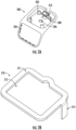
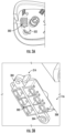
- the conductive plates 210, 410 and conductive plating/coatings 409, 411 are intended to provide contact surfaces for any spilled food/liquid that is energized with voltage from electrical interconnect 302.
- the ground plane interface therefore serves to provide an electrical coupling to the ground fault detection circuit from any energized food/liquid.
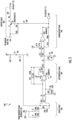
- the output of the second operational amplifier (U4B) then goes HIGH when the input voltage from the first operation amplifier (u4A) exceeds the threshold voltage set by R14 and R15, in this case 0.18V.
- the output stage 508, and in particular, the gate of the transistor (Q1) then goes HIGH which then switches the same to OFF.
- the AND logic discussed above thus preferably prevents the blender MCU 102 from switchably electrically coupling the heating element 108 to the power supply 103 by way of relay 122.
- the HIGH signal output by the second operational amplifier (U4B) of the comparator stage 506 gets received by, for instance, the blender MCU 102 and/or display 112.
- the display 112 can indicate a fault condition has occured, and optionally visualize a mitigating action such as a displaying a message that states "ELECTRICAL FAULT DETECTED. HEATING ELEMENT DISABLED. CLEANING REQUIRED. CONSULT MANUAL.”
- a blender consistent with the present disclosure can continue to power the blender MCU 102 and other circuitry such as the blade motor and motor controller to allow for at least partial use of the blender when in a fault mode.
- the heating element 108 gets disabled to reduce the risk of electric shock, as discussed above, but traditional blender operations which use the blades to chop/puree food and liquids/ice remain available to the user.
- FIG. 6 shows a timing diagram of the GF detection circuit 106 suitable for use in the system of FIG 1 .
- the waveform 601 is that of a typical US household 100VAC at 60Hz, hence the period is 16.6ms and the waveform is positive voltage for half the period and is negative voltage for the other half of the period, e.g., 8.3ms respectively.
- the GF detection circuitry previously described, only positive voltages can be detected. Therefore, whereas the previously described circuitry is advantageous from a cost perspective as it is minimalistic, a drawback with it is that it can only detect ground faults during positive phase of the AC voltage.
- the output from the MCU that controls the relay can be initialized so that the output is a short pulse, followed by an OFF pulse, followed by a continuous ON, waveform 602.
- the short pulse is timed to be 5ms or less and the off pulse is timed to be 16.6ms or a multiple thereof.
- the output of the GF detection circuit is also monitored by the MCU to ensure that the GF circuit is not triggered. If the MCU determines the presence of a GF during initialization, then the MCU terminates the initialization sequence and preferably causes the display of an error message.
- One purpose of the initialization sequence in this embodiment is to ensure that the negative AC voltage having a period of at least 5 ms, or less, can be detected so as to reduce the risk of hazard.
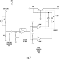
- FIG. 7 shows an another example ground fault (GF) detection circuit 700 suitable for use in the system of FIG 1 .
- This improved circuit utilizes a coupling capacitor and voltage biased AC gain operational amplifier to amplify the AC voltage that couples through the coupling capacitor 701. Similar to the previous circuit, R1 and R2 combine to provide a voltage divider with R8 to attenuate the AC waveform from the ground plane interface. The output from the first operational amplifier is then fed into a dual comparator stage 702 that allows for both positive voltage (comparator 1) and negative voltage (comparator 2) thresholds to be set and to be compared. This enables detection of a ground fault in either the positive or negative phase of the AC voltage.
- GF ground fault
- each of the comparators are fed into an OR gate 703 that then controls the base voltage of Q1, as before. This enables either comparator to turn off the relay as soon as a ground fault is detected, regardless of the AC voltage phase.
- This circuit significantly improves detection relative to the circuit of FIG. 5 , but requires more components to implement.
- FIG. 8 shows a GF/current leak detection circuit configured with a GFCI arrangement that detects an imbalance of current in the live and neutral (return) lines by using sensing transformers and a ground fault interrupter IC, FM2145 manufactured by Fudan Microelectronics.
- a current imbalance is caused when current flows from the live power line to earth ground via the conducting food/liquid and ground plane interface 104. The current is sensed by the sensing transformers that are configured so that the live and neutral lines pass through the center of the transformer/coil windings.
- a detection of current imbalance is outputted from the IC on PIN 5 and is an active HIGH for when imbalance is detected.
- Pin 5 can be connected to the aforementioned output stage 508 to control the relay 122 as well as being connected to the MCU 102 so that an error message can be displayed on display 112.
- the working principle of the circuit shown in FIG 8 is well known and is documented in the datasheet for the FM2145 IC.
- This circuit is shown as an alternate GF detection circuit that can be used within a blender configured consistent with the present disclosure.
- FIG. 9 shows an example blender with integrated food/beverage heating features that implements aspects and embodiments the GF detection circuitry and associated circuitry disclosed herein.
- the present disclosure has identified that common foods/materials placed into blenders include different corresponding resistance values. Stated simply, some materials commonly blended have a low resistance value and therefore will conduct electricity relatively more easily than others. This disclosure has identified that known resistance values can be utilized to further increase accuracy of GF event detection.
- the present disclosure includes a blender with a removable blender jar that includes an integrated heating element that can utilize relatively high voltages, e.g., 120V, to rapidly heat food/beverage items.
- the blender may further include an integrated GF/current leak detection circuit to detect fault conditions and transition to a fault mode that disables supplying electricity to the removable blender jar.
- the blender may further include an integrated GF/current leak detection circuit configured to perform high-side current detection.
- the blender may further include an integrated GF/current leak detection circuit formed of a simple, in-expensive op-amp circuit to perform current sensing via voltage sensing without necessarily utilize galvanically-isolated sensing components.
- the blender may further include an integrated GF/current leak detection circuit that utilizes fast response switching op amps in a to achieve detection of current values exceeding a target threshold within 5ms, and preferably within ⁇ 2-4ms, to comport with regulatory standards governing GFCI operations.
- the blender may further include an integrated GF/current leak detection circuit to provide GF/leak detection without the use of a GFCI-enabled electrical outlet.
- the blender may further include an integrated GF/current leak detection circuit to provide GF/leak detection at a response speed that detects GF/current leaks at a rate faster than GFCI-enabled electrical outlets, e.g., within 4ms or less, and preferably within 1-3ms.
- the blender may further include an integrated GF/current leak detection circuit to switchably decouple a heating element from a power source without interrupting power to a MCU and/or blade motor of the blender.
- the blender may further include an integrated GF/current leak detection circuit to detect a GF/current event based on one or more ground planes disposed around the blender coming into electrical contact with a power rail/terminal of the blender.
- the blender may further include at least one ground plane disposed on the handle of the blender jar, the base of the blender jar and/or the base of the blender, e.g., adjacent the user interface.
- the blender may further include a plurality of ground planes electrically interconnected via a ground plane interface/interconnect, the ground plane interface being coupled to a GF/current leak detection circuit.
- the blender may further include an integrated GF/current leak detection circuit to provide GF/leak detection without the use of a GFCI-enabled electrical outlet.
- the blender may further include a blender with an integrated GF/current leak detection circuit disposed in a housing of the blender.
- the blende may further include an integrated GF/current leak detection circuit configured with a conventional GFCI arrangement, the conventional GFCI arrangement being disposed in the base of the blender.
- the blender may further include an integrated GF/current leak detection circuit configured with a conventional GFCI arrangement, the conventional GFCI arrangement being disposed in the base of the blender and configured to switchably decouple a heating element from a power supply without disrupting power the MCU and/or blade motor of the blender.
- the blender may further include an integrated GF/current leak detection circuit that uses a mechanical relay to de-energize a heating element in response to detecting a GF or current leak.
- the blender may further include an integrated GF/current leak detection circuit to provide GF/leak detection even when the blender is used with a GFCI-enabled electrical outlet.
- the blender may further include a user interface/display that indicates a GF or current leak has occured.
- the blender may further include a user interface/display that indicates a GF or current leak has occured and an action to mitigate the fault.
- the blender may further include a network interface circuit to send a message to an "App" on a computing remote device, e.g., a smart phone, that indicates a GF fault/current leak was detected and steps to mitigate the fault, e.g., cleaning instructions.
- the blender may further include an integrated GF/current leak detection circuit that can be adjusted to target a range of threshold/trigger current values (e.g., to comport with varying government-established GFCI requirements) based on the resistance value of a single resistor.
- an appliance comprising a first portion with a receptacle to couple to a second portion, a first ground plane disposed on a surface defining the first portion, and a ground fault (GF) detection circuit, the GF detection circuit to detect a ground fault event based on a measuring a current induced on the first ground plane and output an electrical signal indicating a fault event.
- GF ground fault
- an appliance comprising a first portion defining a receptacle to receive and removably couple to a second portion, the receptacle having an electrical interconnect to electrically couple the second portion to the first portion, a second portion, the second portion defining a cavity and a heating element, power supply within the first portion and a switching arrangement to switchably electrically couple the heating element to the power supply, at least a first ground plane disposed on the first portion and/or second portion, and a ground fault (GF) detection circuit, the GF detection circuit electrically coupled to the first ground plane, and wherein the GF detection circuit is configured to detect a ground fault event based on a measuring a current induced on the first ground plane, and in response to detecting the ground fault event, cause the switching arrangement to electrically decouple the heating element from the power supply.
- GF ground fault
Landscapes
- Physics & Mathematics (AREA)
- General Physics & Mathematics (AREA)
- Engineering & Computer Science (AREA)
- Power Engineering (AREA)
- Food-Manufacturing Devices (AREA)
Claims (14)
- Gerät (100), wobei das Gerät Folgendes umfasst:einen ersten Abschnitt (116), der eine Aufnahme (202) zum Aufnehmen und entfernbaren Koppeln mit einem zweiten Abschnitt definiert, wobei die Aufnahme eine elektrische Verbindung (302) aufweist, um den zweiten Abschnitt elektrisch mit dem ersten Abschnitt zu koppeln;den zweiten Abschnitt (118), wobei der zweite Abschnitt einen Hohlraum und ein Heizelement (108) definiert;eine Stromversorgung (103) innerhalb des ersten Abschnitts und eine Schaltanordnung (122) zum schaltbaren elektrischen Koppeln des Heizelements mit der Stromversorgung;mindestens eine erste Erdungsebene, die an dem ersten Abschnitt und/oder zweiten Abschnitt angebracht ist; dadurch gekennzeichnet, dass das Gerät (100) ferner eine Erdschluss(ground fault - GF)-Detektionsschaltung (106) umfasst, wobei die GF-Detektionsschaltung elektrisch mit der ersten Erdungsebene gekoppelt ist und wobei die GF-Detektionsschaltung konfiguriert ist, um ein Erdschlussereignis basierend auf einer Messung eines auf der ersten Erdungsebene induzierten Stroms zu detektieren und als Reaktion auf das Detektieren des Erdschlussereignisses die Schaltanordnung zu veranlassen, das Heizelement elektrisch von der Stromversorgung zu entkoppeln, wobei die GF-Detektionsschaltung für eine hochseitige Stromerfassung konfiguriert ist, wobei mindestens die erste Erdungsebene zwischen einer Versorgungsschiene und einer Last des Geräts gekoppelt wird.
- Gerät nach Anspruch 1, ferner umfassend mindestens eine zweite Erdungsebene, die an dem ersten Abschnitt und/oder zweiten Abschnitt angebracht ist, und wobei die GF-Detektionsschaltung elektrisch mit der zweiten Erdungsebene gekoppelt ist, um einen darauf induzierten Strom zu messen und das Erdschlussereignis zu detektieren.
- Gerät nach Anspruch 2, ferner umfassend eine Erdungsebenenschnittstelle (104), wobei die Erdungsebenenschnittstelle elektrisch mit der ersten und der zweiten Erdungsebene gekoppelt ist, sodass die erste und die zweite Erdungsebene eine einzige Erdungsebene bilden.
- Gerät nach Anspruch 3, wobei die Aufnahme eine erste leitfähige Platte (210) beinhaltet und der zweite Abschnitt eine zweite leitfähige Platte (410) beinhaltet und wobei die erste und die zweite leitfähige Platte gemeinsam die Erdungsebenenschnittstelle bereitstellen, wenn sie miteinander gekoppelt sind.
- Gerät nach Anspruch 3, wobei die Erdungsebenenschnittstelle mindestens eine erste leitfähige Platte (210) umfasst, die in der Aufnahme des ersten Abschnitts angebracht ist, wobei die erste leitfähige Platte mindestens einen Vorsprung (214) aufweist, der sich in einen Hohlraum des ersten Abschnitts erstreckt, um elektrisch mit der GF-Detektionsschaltung gekoppelt zu werden.
- Gerät nach Anspruch 1, wobei der zweite Abschnitt einen Mixbecher (118) mit einem Griff (126) umfasst und wobei die erste Erdungsebene an dem Griff angebracht ist und/oder den Mixbecher mindestens teilweise umgibt.
- Gerät nach Anspruch 1, wobei die erste Erdungsebene an dem ersten Abschnitt benachbart zu einer Benutzerschnittstelle angebracht ist.
- Gerät nach Anspruch 1, wobei der erste Abschnitt ferner eine Benutzerschnittstelle (112) beinhaltet und wobei die Benutzerschnittstelle konfiguriert ist, um einen Fehlerzustand basierend auf einem durch die GF-Detektionsschaltung ausgegebenen Signal visuell anzuzeigen oder eine eindämmende Maßnahme zur Behebung des Erdschlussereignisses visuell anzuzeigen.
- Gerät nach Anspruch 1, wobei die GF-Detektionsschaltung Folgendes umfasst:eine Eingangsstufe (502) mit einem Eingangsanschluss zum Koppeln mit mindestens der ersten Erdungsebene und wobei die Eingangsstufe ferner einen Erfassungswiderstand (R8) beinhaltet; eine Differenzstufe (504), die einen ersten Operationsverstärker (U4A) beinhaltet, der Eingänge aufweist, die mit dem ersten bzw. zweiten Ende des Erfassungswiderstands gekoppelt sind, wobei der erste Operationsverstärker eine Spannungsdifferenz basierend auf dem Erfassungswiderstand bestimmt und ein Signal ausgibt, das einen gemessenen Spannungswert basierend auf der Spannungsdifferenz darstellt; undeine Komparatorstufe (506), die einen zweiten Operationsverstärker (U4B) mit einem ersten Eingang zum Koppeln mit dem Ausgang des ersten Operationsverstärkers und einem zweiten Eingang, der mit einer Referenzversorgung gekoppelt ist, aufweist, wobei die Referenzversorgung einem Schwellenstromwert zugeordnet ist, der auf einer vorbestimmten Versorgungsspannung und einem vorbestimmten Widerstandswert mindestens eines Schwellenwertwiderstands (R15) basiert, und wobei der zweite Verstärker ein Signal ausgibt, das auf einer Differenz zwischen dem Schwellenstromwert und dem Ausgang des ersten Operationsverstärkers basiert.
- Gerät nach Anspruch 9, wobei die Schaltanordnung ferner ein Relais (122) umfasst, um das Heizelement selektiv mit der Stromversorgung zu koppeln und zu entkoppeln, wobei die GF-Detektionsschaltung ferner Folgendes umfasst:eine Ausgangsstufe (504), wobei die Ausgangsstufe einen Transistorschalter (Q1) umfasst, wobei der Transistorschalter ein Gatter, das mit dem Ausgang des zweiten Operationsverstärkers gekoppelt ist, einen Emitter zum Koppeln mit einer Mikrosteuerung (102) und einen Kollektor, der mit dem Relais gekoppelt ist, aufweist undwobei der Transistor ein logisches UND-Gatter bereitstellt, um zu verhindern, dass die Mikrosteuerung das Relais veranlasst, das Heizelement schaltbar mit der Stromversorgung zu koppeln, wenn der Ausgang des zweiten Operationsverstärkers einen Erdschluss anzeigt.
- Gerät nach Anspruch 9, wobei der erste und der zweite Operationsverstärker schnell ansprechende Verstärker umfassen.
- Gerät nach Anspruch 1, wobei die GF-Detektionsschaltung konfiguriert ist, um Erdschlussereignisse basierend auf einem gemessenen Strom von mindestens der ersten Erdungsebene zu detektieren, der größer als ein vorbestimmter Schwellenwert ist.
- Gerät nach Anspruch 12, wobei die GF-Detektionsschaltung konfiguriert ist, um Erdschlussereignisse zu detektieren und das Heizelement zu veranlassen, innerhalb einer vorbestimmten Zeitspanne schaltbar von der Stromversorgung abgekoppelt zu werden.
- Gerät nach Anspruch 1, wobei der erste Abschnitt einen Mixerboden (116) umfasst und der zweite Abschnitt einen Mixbecher (118) umfasst.
Applications Claiming Priority (2)
| Application Number | Priority Date | Filing Date | Title |
|---|---|---|---|
| US201962874354P | 2019-07-15 | 2019-07-15 | |
| PCT/US2020/042070 WO2021011611A1 (en) | 2019-07-15 | 2020-07-15 | Appliance with integrated ground fault detection |
Publications (3)
| Publication Number | Publication Date |
|---|---|
| EP4000152A1 EP4000152A1 (de) | 2022-05-25 |
| EP4000152A4 EP4000152A4 (de) | 2023-08-16 |
| EP4000152B1 true EP4000152B1 (de) | 2025-07-09 |
Family
ID=74211285
Family Applications (1)
| Application Number | Title | Priority Date | Filing Date |
|---|---|---|---|
| EP20840080.4A Active EP4000152B1 (de) | 2019-07-15 | 2020-07-15 | Gerät mit integrierter fehlerstromdetektion |
Country Status (4)
| Country | Link |
|---|---|
| US (1) | US12332322B2 (de) |
| EP (1) | EP4000152B1 (de) |
| CN (2) | CN114365364B (de) |
| WO (1) | WO2021011611A1 (de) |
Families Citing this family (3)
| Publication number | Priority date | Publication date | Assignee | Title |
|---|---|---|---|---|
| US12332322B2 (en) * | 2019-07-15 | 2025-06-17 | Sharkninja Operating Llc | Appliance with integrated ground fault detection |
| CN116338519B (zh) * | 2023-06-01 | 2023-09-15 | 中国标准化研究院 | Led显示屏检测方法及其检测装置 |
| US20250386973A1 (en) * | 2024-06-21 | 2025-12-25 | Thomas Lee Binns | Blender with container or jar that is reversibly attachable to any sized disposable bottle of water |
Family Cites Families (24)
| Publication number | Priority date | Publication date | Assignee | Title |
|---|---|---|---|---|
| US3064949A (en) * | 1957-02-27 | 1962-11-20 | Henry A Dewenter | Mixer |
| US3213321A (en) | 1963-05-31 | 1965-10-19 | Charles F Dalziel | Miniature differential circuit breaker |
| US4174073A (en) * | 1978-07-17 | 1979-11-13 | General Electric Company | Multi container interlocked food machine with a safety switch for each container |
| US5109315A (en) | 1988-10-20 | 1992-04-28 | Milton Morse | Safety device for an electrical appliance |
| US4951169A (en) | 1988-10-20 | 1990-08-21 | Milton Morse | Safety device for an electrical appliance |
| US4967308A (en) * | 1989-02-13 | 1990-10-30 | Milton Morse | Enhanced safety device for an electrical appliance |
| US5879173A (en) * | 1995-01-13 | 1999-03-09 | Methode Electronics, Inc. | Removable transceiver module and receptacle |
| US5757598A (en) | 1996-12-27 | 1998-05-26 | Tower Manufacturing Corporation | Ground fault circuit interrupter |
| US5847913A (en) * | 1997-02-21 | 1998-12-08 | Square D Company | Trip indicators for circuit protection devices |
| US6528913B1 (en) * | 1999-11-19 | 2003-03-04 | Emerson Electric Co. | Electric device grounding system |
| US6609821B2 (en) * | 2001-04-13 | 2003-08-26 | Sunbeam Products, Inc. | Blender base with food processor capabilities |
| US20090212967A1 (en) * | 2004-10-15 | 2009-08-27 | Leviton Manufacturing Company, Inc | Circuit Interrupting System with Remote Test And Reset Activation |
| US7623329B2 (en) | 2005-01-04 | 2009-11-24 | Technology Research Corporation | Leakage current detection and interruption circuit with improved shield |
| US7301739B2 (en) * | 2005-10-12 | 2007-11-27 | Chevron U.S.A. Inc. | Ground-fault circuit-interrupter system for three-phase electrical power systems |
| US8154831B2 (en) | 2005-12-23 | 2012-04-10 | General Protecht Group, Inc. | Leakage current detection interrupter with fire protection means |
| US7423854B2 (en) | 2006-07-07 | 2008-09-09 | Technology Research Corporation | Interruption circuit with improved shield |
| CN200965956Y (zh) | 2006-10-23 | 2007-10-24 | 上海益而益电器制造有限公司 | 具有漏电保护功能的电源插头 |
| CN201126958Y (zh) * | 2007-12-07 | 2008-10-01 | 深大宇电器(深圳)有限公司 | 马达温度、电流保护电路,保护器及带保护器的搅拌机 |
| FR2953390B1 (fr) * | 2009-12-03 | 2012-01-06 | Seb Sa | Appareil electromenager de preparation culinaire comportant un recipient de travail comprenant une resistance electrique |
| GB2515763A (en) | 2013-07-02 | 2015-01-07 | Mastercard International Inc | Improvements relating to unpredictable number generation |
| US9089238B2 (en) * | 2013-10-10 | 2015-07-28 | Uni-Splender Corp. | Soup maker |
| US20160225562A1 (en) * | 2015-01-29 | 2016-08-04 | Unilectric, Llc | Enhanced circuit breakers and circuit breaker panels and systems and methods using the same |
| US10111070B2 (en) * | 2015-07-03 | 2018-10-23 | Afero, Inc. | Embedded internet of things (IOT) hub slot for an appliance and associated systems and methods |
| US12332322B2 (en) * | 2019-07-15 | 2025-06-17 | Sharkninja Operating Llc | Appliance with integrated ground fault detection |
-
2020
- 2020-07-15 US US16/929,594 patent/US12332322B2/en active Active
- 2020-07-15 CN CN202080061678.4A patent/CN114365364B/zh active Active
- 2020-07-15 EP EP20840080.4A patent/EP4000152B1/de active Active
- 2020-07-15 CN CN202021395768.0U patent/CN214804288U/zh active Active
- 2020-07-15 WO PCT/US2020/042070 patent/WO2021011611A1/en not_active Ceased
Also Published As
| Publication number | Publication date |
|---|---|
| EP4000152A1 (de) | 2022-05-25 |
| CN114365364A (zh) | 2022-04-15 |
| CN214804288U (zh) | 2021-11-23 |
| CN114365364B (zh) | 2024-06-04 |
| WO2021011611A1 (en) | 2021-01-21 |
| US12332322B2 (en) | 2025-06-17 |
| EP4000152A4 (de) | 2023-08-16 |
| US20210018572A1 (en) | 2021-01-21 |
Similar Documents
| Publication | Publication Date | Title |
|---|---|---|
| EP4000152B1 (de) | Gerät mit integrierter fehlerstromdetektion | |
| JP6633679B2 (ja) | 電流保護回路を有する電気グリルの無線制御及び状態監視 | |
| EP3273558B1 (de) | Elektrischer grill mit stromschutzschaltung | |
| US9312681B2 (en) | Circuit interrupter with over-temperature protection function for power cord | |
| US20180007739A1 (en) | Wireless Control And Status Monitoring For Electric Grill With Current Protection Circuitry | |
| US12357129B2 (en) | Household appliance and method of operating a household appliance | |
| US20060152867A1 (en) | Circuit interrupting apparatus with remote test and reset activation | |
| US20180261993A1 (en) | Automated ground fault interruptor | |
| WO2014028979A1 (en) | An electrical protection device | |
| CN109980603A (zh) | 具有功率监控和控制的便携式发电机 | |
| CA2543042A1 (en) | Breakaway power supply device | |
| US10461520B2 (en) | Controllable test-pulse width and position for self-test ground fault circuit interrupter | |
| US20030043516A1 (en) | Electrical ground fault protection circuit | |
| US10892614B2 (en) | Safety device for a power supply | |
| CN110649432A (zh) | 一种安全插座 | |
| CN210954773U (zh) | 料理机电路及料理机 | |
| US11394202B1 (en) | Alternating current time-sharing outlets and switch box | |
| US9737192B2 (en) | Door latch interruption upon detection of current leakage | |
| WO2012030648A2 (en) | Protected power cord | |
| JP2012156119A (ja) | 電流検知通報器付き電源タップ | |
| US20030218846A1 (en) | Safety device for a delta-connected three-phase electric appliance | |
| AU2019101017A4 (en) | Voltage Protection Device | |
| RO126244A2 (ro) | Sistem de monitorizare a legăturii electrice la împământare | |
| CN209058946U (zh) | 料理机 | |
| JP2008171607A (ja) | 加熱装置 |
Legal Events
| Date | Code | Title | Description |
|---|---|---|---|
| STAA | Information on the status of an ep patent application or granted ep patent |
Free format text: STATUS: THE INTERNATIONAL PUBLICATION HAS BEEN MADE |
|
| PUAI | Public reference made under article 153(3) epc to a published international application that has entered the european phase |
Free format text: ORIGINAL CODE: 0009012 |
|
| STAA | Information on the status of an ep patent application or granted ep patent |
Free format text: STATUS: REQUEST FOR EXAMINATION WAS MADE |
|
| 17P | Request for examination filed |
Effective date: 20220211 |
|
| AK | Designated contracting states |
Kind code of ref document: A1 Designated state(s): AL AT BE BG CH CY CZ DE DK EE ES FI FR GB GR HR HU IE IS IT LI LT LU LV MC MK MT NL NO PL PT RO RS SE SI SK SM TR |
|
| DAV | Request for validation of the european patent (deleted) | ||
| DAX | Request for extension of the european patent (deleted) | ||
| A4 | Supplementary search report drawn up and despatched |
Effective date: 20230718 |
|
| RIC1 | Information provided on ipc code assigned before grant |
Ipc: G01R 31/52 20200101ALI20230712BHEP Ipc: H05H 5/00 20060101ALI20230712BHEP Ipc: H05H 3/00 20060101ALI20230712BHEP Ipc: H02H 5/08 20060101AFI20230712BHEP |
|
| GRAP | Despatch of communication of intention to grant a patent |
Free format text: ORIGINAL CODE: EPIDOSNIGR1 |
|
| STAA | Information on the status of an ep patent application or granted ep patent |
Free format text: STATUS: GRANT OF PATENT IS INTENDED |
|
| INTG | Intention to grant announced |
Effective date: 20250131 |
|
| GRAS | Grant fee paid |
Free format text: ORIGINAL CODE: EPIDOSNIGR3 |
|
| GRAA | (expected) grant |
Free format text: ORIGINAL CODE: 0009210 |
|
| STAA | Information on the status of an ep patent application or granted ep patent |
Free format text: STATUS: THE PATENT HAS BEEN GRANTED |
|
| AK | Designated contracting states |
Kind code of ref document: B1 Designated state(s): AL AT BE BG CH CY CZ DE DK EE ES FI FR GB GR HR HU IE IS IT LI LT LU LV MC MK MT NL NO PL PT RO RS SE SI SK SM TR |
|
| REG | Reference to a national code |
Ref country code: GB Ref legal event code: FG4D |
|
| REG | Reference to a national code |
Ref country code: CH Ref legal event code: EP |
|
| REG | Reference to a national code |
Ref country code: IE Ref legal event code: FG4D |
|
| REG | Reference to a national code |
Ref country code: DE Ref legal event code: R096 Ref document number: 602020054324 Country of ref document: DE |
|
| PGFP | Annual fee paid to national office [announced via postgrant information from national office to epo] |
Ref country code: DE Payment date: 20250916 Year of fee payment: 6 |
|
| PGFP | Annual fee paid to national office [announced via postgrant information from national office to epo] |
Ref country code: GB Payment date: 20250911 Year of fee payment: 6 |
|
| PGFP | Annual fee paid to national office [announced via postgrant information from national office to epo] |
Ref country code: FR Payment date: 20250929 Year of fee payment: 6 |
|
| REG | Reference to a national code |
Ref country code: NL Ref legal event code: MP Effective date: 20250709 |
|
| PG25 | Lapsed in a contracting state [announced via postgrant information from national office to epo] |
Ref country code: PT Free format text: LAPSE BECAUSE OF FAILURE TO SUBMIT A TRANSLATION OF THE DESCRIPTION OR TO PAY THE FEE WITHIN THE PRESCRIBED TIME-LIMIT Effective date: 20251110 |
|
| PG25 | Lapsed in a contracting state [announced via postgrant information from national office to epo] |
Ref country code: NL Free format text: LAPSE BECAUSE OF FAILURE TO SUBMIT A TRANSLATION OF THE DESCRIPTION OR TO PAY THE FEE WITHIN THE PRESCRIBED TIME-LIMIT Effective date: 20250709 |
|
| REG | Reference to a national code |
Ref country code: AT Ref legal event code: MK05 Ref document number: 1812800 Country of ref document: AT Kind code of ref document: T Effective date: 20250709 |
|
| PG25 | Lapsed in a contracting state [announced via postgrant information from national office to epo] |
Ref country code: IS Free format text: LAPSE BECAUSE OF FAILURE TO SUBMIT A TRANSLATION OF THE DESCRIPTION OR TO PAY THE FEE WITHIN THE PRESCRIBED TIME-LIMIT Effective date: 20251109 |
|
| PG25 | Lapsed in a contracting state [announced via postgrant information from national office to epo] |
Ref country code: NO Free format text: LAPSE BECAUSE OF FAILURE TO SUBMIT A TRANSLATION OF THE DESCRIPTION OR TO PAY THE FEE WITHIN THE PRESCRIBED TIME-LIMIT Effective date: 20251009 |
|
| REG | Reference to a national code |
Ref country code: LT Ref legal event code: MG9D |
|
| PG25 | Lapsed in a contracting state [announced via postgrant information from national office to epo] |
Ref country code: AT Free format text: LAPSE BECAUSE OF FAILURE TO SUBMIT A TRANSLATION OF THE DESCRIPTION OR TO PAY THE FEE WITHIN THE PRESCRIBED TIME-LIMIT Effective date: 20250709 |
|
| PG25 | Lapsed in a contracting state [announced via postgrant information from national office to epo] |
Ref country code: FI Free format text: LAPSE BECAUSE OF FAILURE TO SUBMIT A TRANSLATION OF THE DESCRIPTION OR TO PAY THE FEE WITHIN THE PRESCRIBED TIME-LIMIT Effective date: 20250709 |
|
| PG25 | Lapsed in a contracting state [announced via postgrant information from national office to epo] |
Ref country code: HR Free format text: LAPSE BECAUSE OF FAILURE TO SUBMIT A TRANSLATION OF THE DESCRIPTION OR TO PAY THE FEE WITHIN THE PRESCRIBED TIME-LIMIT Effective date: 20250709 |
|
| PG25 | Lapsed in a contracting state [announced via postgrant information from national office to epo] |
Ref country code: GR Free format text: LAPSE BECAUSE OF FAILURE TO SUBMIT A TRANSLATION OF THE DESCRIPTION OR TO PAY THE FEE WITHIN THE PRESCRIBED TIME-LIMIT Effective date: 20251010 |
|
| PG25 | Lapsed in a contracting state [announced via postgrant information from national office to epo] |
Ref country code: SE Free format text: LAPSE BECAUSE OF FAILURE TO SUBMIT A TRANSLATION OF THE DESCRIPTION OR TO PAY THE FEE WITHIN THE PRESCRIBED TIME-LIMIT Effective date: 20250709 |
|
| PG25 | Lapsed in a contracting state [announced via postgrant information from national office to epo] |
Ref country code: LV Free format text: LAPSE BECAUSE OF FAILURE TO SUBMIT A TRANSLATION OF THE DESCRIPTION OR TO PAY THE FEE WITHIN THE PRESCRIBED TIME-LIMIT Effective date: 20250709 |
|
| PG25 | Lapsed in a contracting state [announced via postgrant information from national office to epo] |
Ref country code: BG Free format text: LAPSE BECAUSE OF FAILURE TO SUBMIT A TRANSLATION OF THE DESCRIPTION OR TO PAY THE FEE WITHIN THE PRESCRIBED TIME-LIMIT Effective date: 20250709 Ref country code: PL Free format text: LAPSE BECAUSE OF FAILURE TO SUBMIT A TRANSLATION OF THE DESCRIPTION OR TO PAY THE FEE WITHIN THE PRESCRIBED TIME-LIMIT Effective date: 20250709 |
|
| PG25 | Lapsed in a contracting state [announced via postgrant information from national office to epo] |
Ref country code: RS Free format text: LAPSE BECAUSE OF FAILURE TO SUBMIT A TRANSLATION OF THE DESCRIPTION OR TO PAY THE FEE WITHIN THE PRESCRIBED TIME-LIMIT Effective date: 20251009 |
|
| PG25 | Lapsed in a contracting state [announced via postgrant information from national office to epo] |
Ref country code: ES Free format text: LAPSE BECAUSE OF FAILURE TO SUBMIT A TRANSLATION OF THE DESCRIPTION OR TO PAY THE FEE WITHIN THE PRESCRIBED TIME-LIMIT Effective date: 20250709 |
|
| REG | Reference to a national code |
Ref country code: CH Ref legal event code: H13 Free format text: ST27 STATUS EVENT CODE: U-0-0-H10-H13 (AS PROVIDED BY THE NATIONAL OFFICE) Effective date: 20260224 |
|
| PG25 | Lapsed in a contracting state [announced via postgrant information from national office to epo] |
Ref country code: RO Free format text: LAPSE BECAUSE OF FAILURE TO SUBMIT A TRANSLATION OF THE DESCRIPTION OR TO PAY THE FEE WITHIN THE PRESCRIBED TIME-LIMIT Effective date: 20250709 Ref country code: LU Free format text: LAPSE BECAUSE OF NON-PAYMENT OF DUE FEES Effective date: 20250715 |
|
| REG | Reference to a national code |
Ref country code: BE Ref legal event code: MM Effective date: 20250731 |
|
| PG25 | Lapsed in a contracting state [announced via postgrant information from national office to epo] |
Ref country code: SM Free format text: LAPSE BECAUSE OF FAILURE TO SUBMIT A TRANSLATION OF THE DESCRIPTION OR TO PAY THE FEE WITHIN THE PRESCRIBED TIME-LIMIT Effective date: 20250709 |
|
| PG25 | Lapsed in a contracting state [announced via postgrant information from national office to epo] |
Ref country code: DK Free format text: LAPSE BECAUSE OF FAILURE TO SUBMIT A TRANSLATION OF THE DESCRIPTION OR TO PAY THE FEE WITHIN THE PRESCRIBED TIME-LIMIT Effective date: 20250709 |
|
| PG25 | Lapsed in a contracting state [announced via postgrant information from national office to epo] |
Ref country code: BE Free format text: LAPSE BECAUSE OF NON-PAYMENT OF DUE FEES Effective date: 20250731 Ref country code: IT Free format text: LAPSE BECAUSE OF FAILURE TO SUBMIT A TRANSLATION OF THE DESCRIPTION OR TO PAY THE FEE WITHIN THE PRESCRIBED TIME-LIMIT Effective date: 20250709 |
|
| PG25 | Lapsed in a contracting state [announced via postgrant information from national office to epo] |
Ref country code: CH Free format text: LAPSE BECAUSE OF NON-PAYMENT OF DUE FEES Effective date: 20250731 Ref country code: CZ Free format text: LAPSE BECAUSE OF FAILURE TO SUBMIT A TRANSLATION OF THE DESCRIPTION OR TO PAY THE FEE WITHIN THE PRESCRIBED TIME-LIMIT Effective date: 20250709 |
|
| PG25 | Lapsed in a contracting state [announced via postgrant information from national office to epo] |
Ref country code: EE Free format text: LAPSE BECAUSE OF FAILURE TO SUBMIT A TRANSLATION OF THE DESCRIPTION OR TO PAY THE FEE WITHIN THE PRESCRIBED TIME-LIMIT Effective date: 20250709 Ref country code: SK Free format text: LAPSE BECAUSE OF FAILURE TO SUBMIT A TRANSLATION OF THE DESCRIPTION OR TO PAY THE FEE WITHIN THE PRESCRIBED TIME-LIMIT Effective date: 20250709 |