EP4000131B1 - Multi-panel array antenna - Google Patents
Multi-panel array antenna Download PDFInfo
- Publication number
- EP4000131B1 EP4000131B1 EP20736356.5A EP20736356A EP4000131B1 EP 4000131 B1 EP4000131 B1 EP 4000131B1 EP 20736356 A EP20736356 A EP 20736356A EP 4000131 B1 EP4000131 B1 EP 4000131B1
- Authority
- EP
- European Patent Office
- Prior art keywords
- radiating
- array antenna
- antenna
- panels
- shaping
- Prior art date
- Legal status (The legal status is an assumption and is not a legal conclusion. Google has not performed a legal analysis and makes no representation as to the accuracy of the status listed.)
- Active
Links
- 238000007493 shaping process Methods 0.000 claims description 51
- 238000000034 method Methods 0.000 claims description 17
- 230000005540 biological transmission Effects 0.000 claims description 16
- 238000012512 characterization method Methods 0.000 claims description 3
- 230000005855 radiation Effects 0.000 description 16
- 238000010586 diagram Methods 0.000 description 13
- 230000010363 phase shift Effects 0.000 description 11
- 238000004364 calculation method Methods 0.000 description 5
- 230000006870 function Effects 0.000 description 5
- 241000897276 Termes Species 0.000 description 4
- 238000003491 array Methods 0.000 description 4
- 238000004519 manufacturing process Methods 0.000 description 4
- 230000003071 parasitic effect Effects 0.000 description 4
- 230000003321 amplification Effects 0.000 description 3
- 230000008901 benefit Effects 0.000 description 3
- 230000015572 biosynthetic process Effects 0.000 description 3
- 238000003199 nucleic acid amplification method Methods 0.000 description 3
- 230000002238 attenuated effect Effects 0.000 description 2
- 230000000694 effects Effects 0.000 description 2
- 238000005259 measurement Methods 0.000 description 2
- 238000011282 treatment Methods 0.000 description 2
- 241000985719 Antennariidae Species 0.000 description 1
- 230000006978 adaptation Effects 0.000 description 1
- 230000008859 change Effects 0.000 description 1
- 239000012141 concentrate Substances 0.000 description 1
- 230000008878 coupling Effects 0.000 description 1
- 238000010168 coupling process Methods 0.000 description 1
- 238000005859 coupling reaction Methods 0.000 description 1
- 238000005315 distribution function Methods 0.000 description 1
- 238000009434 installation Methods 0.000 description 1
- 239000011159 matrix material Substances 0.000 description 1
- 230000010287 polarization Effects 0.000 description 1
- 230000008569 process Effects 0.000 description 1
- 230000006798 recombination Effects 0.000 description 1
- 238000005215 recombination Methods 0.000 description 1
- 230000009467 reduction Effects 0.000 description 1
Images


Classifications
-
- H—ELECTRICITY
- H01—ELECTRIC ELEMENTS
- H01Q—ANTENNAS, i.e. RADIO AERIALS
- H01Q21/00—Antenna arrays or systems
- H01Q21/29—Combinations of different interacting antenna units for giving a desired directional characteristic
-
- H—ELECTRICITY
- H01—ELECTRIC ELEMENTS
- H01Q—ANTENNAS, i.e. RADIO AERIALS
- H01Q3/00—Arrangements for changing or varying the orientation or the shape of the directional pattern of the waves radiated from an antenna or antenna system
- H01Q3/26—Arrangements for changing or varying the orientation or the shape of the directional pattern of the waves radiated from an antenna or antenna system varying the relative phase or relative amplitude of energisation between two or more active radiating elements; varying the distribution of energy across a radiating aperture
-
- G—PHYSICS
- G01—MEASURING; TESTING
- G01S—RADIO DIRECTION-FINDING; RADIO NAVIGATION; DETERMINING DISTANCE OR VELOCITY BY USE OF RADIO WAVES; LOCATING OR PRESENCE-DETECTING BY USE OF THE REFLECTION OR RERADIATION OF RADIO WAVES; ANALOGOUS ARRANGEMENTS USING OTHER WAVES
- G01S7/00—Details of systems according to groups G01S13/00, G01S15/00, G01S17/00
- G01S7/02—Details of systems according to groups G01S13/00, G01S15/00, G01S17/00 of systems according to group G01S13/00
- G01S7/28—Details of pulse systems
- G01S7/2813—Means providing a modification of the radiation pattern for cancelling noise, clutter or interfering signals, e.g. side lobe suppression, side lobe blanking, null-steering arrays
-
- H—ELECTRICITY
- H01—ELECTRIC ELEMENTS
- H01Q—ANTENNAS, i.e. RADIO AERIALS
- H01Q21/00—Antenna arrays or systems
- H01Q21/06—Arrays of individually energised antenna units similarly polarised and spaced apart
- H01Q21/22—Antenna units of the array energised non-uniformly in amplitude or phase, e.g. tapered array or binomial array
Definitions
- the invention lies in the field of antenna devices, such as radar antennas, and relates more particularly to the production of a large array antenna.
- Array antennas are antennas whose radiating face is made up of elementary radiating elements mounted on a mechanical structure.
- the spacing between the radiating elements, or pitch of the radiating face, is fixed and is linked to the operating frequency band of the antenna.
- By modifying the phase of the signal transmitted or received by each of the radiating elements it is possible to direct the maximum gain of the antenna in a given direction, which makes them particularly suitable for radar applications aimed at scanning a geographical area or to follow the movement of a target over time (electronically scanned antennas).
- the radiation distribution function consists of a main lobe, or beam, and side lobes. Modifying the amplitude of the elementary signals also makes it possible to control the quality of the beams formed and advantageously their secondary lobe levels.
- the size of an array antenna is adjusted according to a specific operational need. Once the antenna is built, the performance of the antenna such as its gain or its angular resolution is fixed.
- the patent US 6,496,158 B1 describes a multi-panel antenna system in which the space between panels is adjusted to limit intermodulation products.
- the patent application FR 2.784.803 A1 deals with an antenna comprising several sub-arrays.
- the patent application US 4,596,986 A describes a method for canceling out jammers arriving in the secondary lobe of an array antenna.
- the patent application US 2009/135085 A1 describes a modular array antenna.
- the patent application US 2015/349434 A1 describes an array antenna formed from two arrays of radiating elements.
- the sum used to calculate the shaping coefficient applied to the radiating elements also includes a calibration coefficient.
- the shaping coefficient making it possible to orient the maximum gain of the antenna in a given direction is calculated from the desired pointing direction of the array antenna, the frequency of the radio frequency signal, the position of the radiating element considered within the array antenna, and the total number of radiating elements of the array antenna.
- the shaping coefficient making it possible to orient the maximum gain of the antenna in the direction of at least one secondary lobe resulting from gaps between the radiating panels of the array antenna is calculated from of the direction of said secondary lobe, of the frequency of the radio frequency signal, of the position of the radiating element considered within the array antenna, and of the total number of radiating elements of the array antenna.
- the array antenna further comprises means for summing the signals received from each of the radiating and shaped elements.
- the method further comprises a preliminary step of characterizing secondary lobes resulting from gaps between the radiating panels of the array antenna.
- the present invention proposes to respond to these problems by producing an array antenna from array antennas of smaller dimensions.
- it is possible to dynamically adjust the size and performance of the antenna according to the need for range, by adding or removing antennas.
- This association of elements independent from a mechanical point of view results in a large, high-performance radar whose transport and deployment is easy compared to the transport and deployment of an antenna of equivalent size.
- FIG. 1a schematically represents the radiating panel of a unitary array antenna. It comprises a radiating panel 100 composed of a plurality of radiating elements 101 distributed according to a mesh of regular pitch.
- the radio frequency (RF) signal to be transmitted is shaped and then transmitted by each of the radiating elements.
- Setting form consists of modifying the phase of the RF signal, and advantageously its amplitude, for each of the radiating elements independently so as to direct the maximum gain of the antenna in the desired direction.
- the RF signal received from each radiating element is shaped to obtain the maximum gain of the antenna in a given direction.
- the shaping of the beams is given by a control law, a phase law 103 and advantageously an amplitude law 102, to be applied to the RF signal to be transmitted or received on each of the radiating elements of the radiating panel.
- the applied phase shift makes it possible to orient the maximum gain of the antenna in the desired direction. This phase shift is constant between two consecutive radiating elements, and its value is directly linked to the wavelength of the RF signal, the pitch of the radiating face and the pointing of the desired beam.
- the amplitude control law makes it possible to concentrate the power at the center of the antenna, and therefore to reduce the level of secondary lobes.
- the amplitude control law is therefore advantageous but is not essential for pointing the antenna beam, most of the scanning array antennas known to the state of the art being controlled only by phase control. on the show.
- FIG. 1b represents a configuration of four disjoint unitary radiating panels, independent in the sense of the antenna arrays.
- the radiating panels 110, 111, 112 and 113 all focus in the same angular direction, without taking into account the presence of neighboring panels.
- the same control law 120, 121, 122, 123 is assigned to each of the radiating panels.
- the total signal transmitted is the recombination of each of the signals, which makes it possible to improve the transmission power.
- the signal received on each of the radiating panels can be summed in order to improve the signal-to-noise ratio.
- the angular resolution is not improved compared to the configuration of the figure 1a .
- the emissions from the different panels interfere, which causes loss of gain and the appearance of secondary lobes, particularly for significant offsets.
- FIG 1c represents a radiating panel 130 for an array antenna made from the joint association of four radiating panels of smaller size, as shown in figure 1a .
- the control law 131 applied to the radiating elements is adapted in relation to the total surface of the radiating panel 130, via a centralized calculation of the phases, and advantageously of the amplitudes, of focusing to be applied.
- the angular resolution and gain of the antenna are improved compared to the configuration of the figure 1a .
- this case is a theoretical case towards which we must aim, in which the radiant panel made from several joined radiant panels is continuous.
- the antennas have edges which make it impossible to obtain a perfect joined network like the one shown in Figure figure 1c .
- FIG 1d represents a radiating panel for an array antenna made from the disjoint association of four disjoint unit panels 141, 142, 143 and 144, as shown in figure 1a .
- the control law 150 applied to the radiating elements is adapted in relation to the total surface of the radiating panel 130, via a centralized calculation of the phases, and advantageously of the amplitudes, of focusing to be applied.
- the radiating panels cannot be arranged in a contiguous manner because of their edges, the overall network antenna is not continuous.
- the spaces 151, 152 and 153 between radiating panels (translation along three axes) and their alignment (rotations along three axes) result in breaks in the total radiating face.
- the object of the present invention consists of producing an array antenna from several radiating panels arranged side by side in a non-contiguous manner, as in the example of the figure 1d , and to modify the control law of the radiating elements so as to take into account the spaces and alignment differences between the various radiating panels during the formation of the beam.
- the overall antenna is seen as corresponding to the sum of two radiating surfaces: a first radiating surface corresponding to the entire surface of the radiating panels (including the spaces between radiating panels), and a second surface corresponding to the spaces between the radiating panels. This second surface is equivalent to a virtual network of small radiating surfaces generating interference which degrades the beam generated by the first surface.
- the spaces between radiating panels are small compared to the dimension of the latter (typically less than a few wavelengths) it is possible to evaluate the radiation diagram of the second surface, and to contrast it with the radiation diagram of the first surface to obtain an overall radiation pattern whose level of secondary lobes caused by the non-joint nature of the radiating panels is reduced. This is possible by modifying the amplitude and phase coefficients of the signals transmitted to the radiating elements forming the overall radiating surface.
- the radiating panels are arranged side by side horizontally, so as to increase the width of the overall array antenna, and thus improve the angular resolution in azimuth.
- they could equally be arranged side by side vertically to improve the angular resolution in elevation, or along both axes.
- FIG. 2 represents the main elements of a unitary array antenna according to the state of the art.
- array antenna encompasses both the radiating panels and the components necessary to implement the beamforming treatments.
- the array antennas presented below by way of illustration are used in reception, because for radar applications, the RF signal is generally transmitted using high efficiency amplifiers, such as for example amplifiers. class C, not allowing variation in amplitude of the transmitted signal. It is therefore in reception that the invention applies most completely, on the one hand for beams with low secondary lobe levels, and on the other hand because the modulation of signal control is possible in phase and in amplitude. However, the invention would be applied in the same way to control the beam in transmission.
- the radiant panel 200 of the figure 2 includes M radiating elements 201 to 20M.
- a circulator 211 to 21M makes it possible to switch each radiating element between a transmission function in which it receives a signal to be transmitted, and a reception function in which it receives an RF signal and transmits it to dedicated processing equipment.
- the RF signal to be transmitted is generated by dedicated equipment 270 for generating an analog RF signal, amplified by an amplification chain common to all the radiating elements or an amplification chain 221 at 22M specific to each radiating element, then emitted by the radiating elements.
- the signal received on each of the radiating elements is transmitted to a low noise amplifier 231 at 23M then digitized by an analog to digital converter 241 at 24M.
- a shaping coefficient specific to each radiating element ideally corresponding to a phase shift and an attenuation, is applied at 251 to 25M on the digital signal.
- the value of the phase shift and attenuation is adjustable and depends on the desired direction of the antenna beam.
- These coefficients are generally pre-calculated and stored in a table ⁇ 1260 including all the attenuation coefficients and phase shifts of the different radiating elements as a function of the direction of the antenna beam.
- the values of the table 260 are programmed according to the desired direction by a radar management device 261.
- the RF signals received from the different radiating elements and shaped are summed 262, then processed by the signal processing algorithms 263 specific to the intended application.
- the values in the table ⁇ 1260 are calculated theoretically from the number of radiating elements, their respective positions, the size and pitch of the radiating mesh, as well as the operating frequency considered.
- they can be supplemented by adjustment coefficients taking into account the imperfections of the radiation diagrams of each radiating element and the imperfections linked to the structure of the radiating panel, these imperfections being characterized in the factory during a calibration phase.
- a usual method consists of carrying out near field measurements of the antenna panel to obtain by back-propagation (inverse Fourier transform type calculation) the signal level produced for each radiating element and to know the deviation from the theoretical signal distribution giving maximum focus.
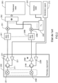
- FIG. 3 represents the main elements of an array antenna according to one embodiment of the invention.
- This antenna comprises N radiating panels 300-1, 300-N as described in figure 2 , connected to a centralized management device 361 of the control laws, as represented in figure 1d .
- Each radiating panel therefore comprises M radiating elements 301-1, 30M-1, 301-N, 30M-N, each connected to a circulator 311-1, 31M-1, 311-N, 31M-N allowing switching between emission and reception.
- the array antenna was composed of several radiating panels of strictly identical sizes.
- the invention would apply equivalently for an array antenna composed of radiating panels of different sizes.
- the results obtained would be comparable.
- the analog RF signal to be transmitted is generated by a device 370 and amplified by the amplification chains 321-1, 32M-1, 321-N, 32M-N.
- the signals received from each radiating element are amplified by the low noise amplifiers 331-1, 33M-1, 331-N, 33M-N, digitized by the analog-digital converters 341-1, 34M-1, 341- N, 34M-N, then shaped.
- the table of coefficients ⁇ 1 360-1 contains the attenuations and phase shifts applied to each of the RF signals received from the radiating elements 351-1, 35M-1 of the antenna 1, while the table of coefficients ⁇ N 360-N contains the attenuations and phase shifts applied to the RF signals received from the radiating elements 351-N, 35M-N of the antenna N.
- the signals are then summed by adders 362-1 and 362-N.
- the shaping coefficients ⁇ 1 and ⁇ N are provided by a higher level table 380, which includes the coefficient tables for one or more radiant panel configurations.
- a centralized radar management device 361 is responsible for calculating or selecting the coefficient tables based on the arrangement information of the radiating panels, the operating frequency and the intended orientation of the antenna beam.
- This device is generally in the form of software embedded on a calculation device such as a processor, a digital signal processor (better known by the English acronym DSP for “Digital Signal Processor”), or a specialized circuit. such as an ASIC (English acronym for “Application Specifies Integrated Circuit”) or an FPGA (English acronym for “Field-Programmable Gate Array”).
- the signals received from the different antennas are summed 381, then transmitted to radar processing software 363 for the implementation of the signal processing algorithms necessary for the targeted applications.
- the multi-panel antenna according to the invention has the advantage that the control law of the weightings applied to the RF signals received from the different radiating elements takes into account the entire radiating face of the multi-panel antenna, the frequency of operation and the desired pointing direction, but also the imperfections due to breaks in the radiating face caused by the spaces between radiating panels and their alignment variations.
- FIG 4a represents, in dotted lines 401, the radiation diagram obtained by the implementation of an ideal joined network of radiating panels, as represented in figure 1c .
- the radiation pattern is shown for angles between -90° and +90°.
- the main lobe which corresponds to the pointing direction of the beam, points in the example at 50° azimuth. In other directions, emissions are attenuated by at least 35 dB relative to the main lobe.
- FIG 4a also represents, in solid lines 402, the radiation diagram obtained by the implementation of a disjoint network of radiating panels, as represented in figure 1d , without compensation for interference generated by gaps between panels.
- Side lobes whose level is approximately 20 dB to 30 dB below the level of the main lobe, appear at angles of approximately -70°, -45°, -25°, -5° and 30°.
- One of the aims of the invention is to reduce the level or eliminate these secondary lobes, which are here approximately 10 to 20 dB higher than for the joined network.
- the first term of the equation, in W c [ K p , ( r ⁇ n ⁇ ) m ], corresponds to the P shaping coefficients ⁇ c which must be applied to each of the radiating elements to point the beam of the array antenna in each of the P directions K p of the secondary lobes of the antenna, when we consider a control law taking into account the entire network antenna, i.e. W vs K p ⁇ r ⁇ not ⁇ m ⁇ ⁇ vs K p ⁇ r ⁇ 1 ⁇ m ⁇ 1 . . M ⁇ 1 ⁇ ... ⁇ vs K p ⁇ r ⁇ NOT ⁇ m ⁇ 1 . . M ⁇ NOT ⁇ .
- the corresponding shaping coefficient ⁇ c is obtained from the associated control law making it possible to point the beam of the array antenna in the direction of the secondary lobe considered, at the desired level. It is therefore a complex amplitude/phase coefficient.
- the coefficient ⁇ co can therefore correspond to a phase shift only, or advantageously be a complex amplitude/phase coefficient.
- the third term of the equation, in W [ k , ( r_r ⁇ n ⁇ ) m ], corresponds to the phase factor of the signal captured by each radiating element to take into account interference between the radiating elements.
- This phase factor may contain a calibration coefficient generally obtained during a calibration phase carried out during the manufacture of each radiating panel.
- the invention proposes to apply to each of the radiating elements a complex shaping coefficient calculated on the principle of subtraction in the known direction of each of the parasitic lobes of an equivalent lobe of level equal to that of the parasitic lobe.
- Knowledge of the parasitic lobe is determined by knowledge of the position of the elements of the global network installed on its site of use.
- the coefficient of a radiating element is equal to the coefficient ⁇ co , required to orient the maximum gain of the antenna in a given direction, minus the coefficients ⁇ c corresponding to the directions of the secondary lobes affected by the levels of the parasitic secondary lobes. In this way, the effect of the spaces between radiating panels is compensated and the level of the secondary lobes reduced.
- phase and amplitude shaping coefficient applied to each radiating element takes into account the calibration coefficient taken into account in the W of equation (1).
- figure 4b represents, in dotted lines 411, the radiation diagram obtained by a disjoint network of radiating panels, as shown in figure 1d , without compensation for interference due to gaps between panels, corresponding to the 402 radiation pattern of the figure 4a .
- the radiation diagram 412 in solid lines, is obtained by the same disjoint network of radiating panels, after implementation of the compensation of the shaping coefficients described by the invention.
- the secondary lobes at -70°, -45°, -25°, -5° and 30° have been attenuated and returned to levels comparable to those obtained for an ideal antenna composed of joined radiating panels, i.e. a reduction of 10 to 20dB in the level of each of these secondary lobes.
- the multi-antenna radiating panel according to the invention therefore makes it possible to reduce the level of secondary lobes generated by the gaps between radiating panels.
- the number of side lobes generated by the spaces between radiating panels depends on the operating frequency and the pointing direction.
- the number P of secondary lobes processed depends on their level and the requirements on the directivity of the beam, and must therefore be evaluated with regard to operational needs and the available computing power.
- FIG 5a represents the beam of an array antenna made up of an ideal joined array of radiating panels.
- the beam is well centered around the intended direction.
- FIG 5b represents the antenna beam emitted by the same ideal joined array of radiating panels when the phase and amplitude control coefficients are modified to take into account the interference generated by the spaces between the radiating panels.
- the beam is more diffuse than that of the figure 5a .
- the beam tends towards that of the figure 5a .
- the two parts can be implemented independently. Indeed, the first can be carried out before installing the antenna for use in the field of operation since the interference generated is identical for two situations where the number of radiating panels and their arrangement is similar.
- the characterization of the interference can then be made during the installation of the antenna, beforehand, from the radiating panels used to constitute the network antenna, from other radiating panels of the same sizes, or even from software for simulating network antenna radiation.
- N radiating panels are arranged side by side, horizontally, vertically or in both directions.
- the relative positions of the radiating panels that is to say the differences between these different panels and their orientations, are recorded and stored in a memory.
- these positions can be obtained by measurements carried out by metrology measuring equipment integrated into the radar such as laser range finders.
- the array antenna is configured to emit an RF signal in a given pointing direction, preferably in an environment reproducing the propagation of the signal in free space, such as for example an anechoic chamber.
- the maximum gain of the antenna is oriented by shaping the RF signal transmitted to each of the radiating elements, considering a global control law taking into account the entire network antenna.
- the antenna radiation pattern is then measured, in order to identify the direction of the secondary lobes generated by the gaps between the radiating panels. The operation is repeated for each of the pointing directions considered in the operational context.
- the characterization can also be carried out in software.
- a model corresponding to the multi-radiating panel array antenna is constituted in digital simulation software implemented in order to measure the radiation pattern, and to identify the directions and levels of the secondary lobes associated with each direction. envisaged pointing of the antenna.
- the direction of the secondary lobes generated by the gaps between radiating panels of the multi-panel array antenna is known for the intended pointing directions. These directions are stored in a memory allowing access to them when implementing the array antenna.
- steps 601 and 602 can be repeated for different arrangements of the radiating panels, by varying their number and/or their respective arrangements (positions and/or gaps).
- the method also includes a step 603 of implementing the transmission and/or reception of RF signals taking into account the position of the secondary lobes as a function of the arrangement of the radiating panels.
- a step 603 of implementing the transmission and/or reception of RF signals taking into account the position of the secondary lobes as a function of the arrangement of the radiating panels.
- Figure 7 represents in more detail this step of implementing a transmission/reception method on a multi-panel antenna according to one embodiment of the invention.
- a device for centralized management of control laws such as device 361 shown in Figure 3 , is configured to take into account the relative position 701 of the antenna panels and the position 702 of the radiating elements within each radiating panel to determine an absolute position 703 of each of the radiating elements within the array antenna.
- Operating parameters 704 are known to the centralized device, including a desired azimuth and elevation for pointing 705 of the antenna beam, as well as an operating frequency 706.
- the antenna management device is configured to calculate the control law making it possible to determine the set of coefficients W co 707 applicable to the network antenna to direct the antenna beam in the desired pointing direction, without taking into account the interference generated by the use of different panels radiant.
- the antenna management device is also configured to calculate the control law(s) making it possible to determine the set of coefficients W c 708 applicable to the network antenna to attenuate the rises of linked secondary lobes due to the use of different radiant panels. These coefficients are calculated from the information concerning the secondary lobes stored in memory during step 602, selected as a function of the arrangement of radiating panels, the targeted pointing direction and the operating frequency of the antenna.
- the antenna management device is also configured to retrieve from a memory a set of calibration coefficients W 709 corresponding to factory settings 710 associated with the radiating elements for the operating frequency 706.
- the antenna management device is also configured to calculate an overall shaping coefficient 711 for each of the radiating elements, corresponding to the sum of the coefficient ⁇ co (from the set of coefficients W co 707) with the opposite of the P coefficients ⁇ c (from the set of coefficients W c 708), supplemented where appropriate by the associated calibration coefficient (from the set of coefficients W 709).
- Each global shaping coefficient is used to shape the signals received from the corresponding radiating element 712 of the array antenna.
- Treatments 707, 708 and 711 of the Figure 7 are made at each change of one of the operating parameters 704, such as the pointing direction of the antenna, the frequency or the number/arrangement 701 of the radiating panels.
- the coefficients W c corresponding to the shaping coefficients applicable to the radiating elements to reduce the level of the secondary lobes for each of the pointing directions considered are calculated during step 602 of characterizing the secondary lobes, then stored in a memory allowing access to them during implementation of the array antenna.
- Step 708 is then limited to the selection of the set of coefficients corresponding to the arrangement and operating parameters of the array antenna.
- the sets of shaping coefficients stored in memory correspond to the sum of the coefficient W co and the opposite of the coefficient(s) W c for each radiating element of the antenna.
- This new set of coefficients is associated with parameters concerning the pointing direction, frequency and arrangement of the radiating panels.
- the calibration coefficients W are also taken into account in the sum stored in memory during step 602.
- the array antenna which is the subject of the present invention consists of a plurality of independent radiating panels connected to a centralized device for managing beam formation. It therefore responds well to the expressed need for ease of adaptation of performance to operational needs since it is enough to add radiating panels to increase the size of the antenna and therefore improve its performance. It also responds well to the need for ease of transport and deployment because the elements that compose it are mechanically independent, and can be transported independently. Finally, its implementation complexity is low since the interference generated by the different panels can be characterized and shaping parameters calculated before the implementation of the antenna on the field of operations.
Landscapes
- Engineering & Computer Science (AREA)
- Radar, Positioning & Navigation (AREA)
- Remote Sensing (AREA)
- Computer Networks & Wireless Communication (AREA)
- Physics & Mathematics (AREA)
- General Physics & Mathematics (AREA)
- Variable-Direction Aerials And Aerial Arrays (AREA)
Description
L'invention se situe dans le domaine des dispositifs antennaires, comme les antennes radar, et porte plus particulièrement sur la réalisation d'une antenne réseau de grande taille.The invention lies in the field of antenna devices, such as radar antennas, and relates more particularly to the production of a large array antenna.
Les antennes réseau sont des antennes dont la face rayonnante est constituée d'éléments rayonnants élémentaires montés sur une structure mécanique. L'écartement entre les éléments rayonnants, ou pas de la face rayonnante, est figé et est lié à la bande de fréquence de fonctionnement de l'antenne. En modifiant la phase du signal transmis ou reçu par chacun des éléments rayonnants, il est possible d'orienter le gain maximum de l'antenne dans une direction donnée, ce qui les rend particulièrement adaptées pour les applications radars visant à balayer une zone géographique ou à suivre le déplacement d'un objectif au cours du temps (antennes à balayage électronique). La fonction de répartition du rayonnement est constituée d'un lobe principal, ou faisceau, et de lobes secondaires. La modification de l'amplitude des signaux élémentaires permet en outre de contrôler la qualité des faisceaux formées et avantageusement leur niveaux de lobes secondaires.Array antennas are antennas whose radiating face is made up of elementary radiating elements mounted on a mechanical structure. The spacing between the radiating elements, or pitch of the radiating face, is fixed and is linked to the operating frequency band of the antenna. By modifying the phase of the signal transmitted or received by each of the radiating elements, it is possible to direct the maximum gain of the antenna in a given direction, which makes them particularly suitable for radar applications aimed at scanning a geographical area or to follow the movement of a target over time (electronically scanned antennas). The radiation distribution function consists of a main lobe, or beam, and side lobes. Modifying the amplitude of the elementary signals also makes it possible to control the quality of the beams formed and advantageously their secondary lobe levels.
Actuellement, la dimension d'une antenne réseau est ajustée en fonction d'un besoin opérationnel précis. Une fois l'antenne construite, les performances de l'antenne telles que son gain ou sa résolution angulaire sont figées.Currently, the size of an array antenna is adjusted according to a specific operational need. Once the antenna is built, the performance of the antenna such as its gain or its angular resolution is fixed.
Pour augmenter les performances, il n'y a pas d'autre choix que de développer une nouvelle antenne de plus grande taille comprenant un plus grand nombre d'éléments rayonnants, ce qui s'avère long et coûteux. En outre, les difficultés et coûts de transport et de déploiement de l'antenne augmentent avec sa taille.To increase performance, there is no other choice than to develop a new, larger antenna including a greater number of radiating elements, which proves to be time-consuming and expensive. In addition, the difficulties and costs of transporting and deploying the antenna increase with its size.
Il existe donc un besoin pour un système permettant d'adapter la taille d'une antenne réseau au besoin opérationnel sans requérir la fabrication d'une nouvelle antenne. Il existe également un besoin pour une antenne réseau de taille importante pouvant être facilement transportée et déployée.There is therefore a need for a system making it possible to adapt the size of an array antenna to operational needs without requiring the manufacture of a new antenna. There is also a need for a large array antenna that can be easily transported and deployed.
Le brevet
A cet effet, l'invention porte sur une antenne réseau comprenant :
- une pluralité de panneaux rayonnants mécaniquement disjoints disposés côte à côte, chaque panneau rayonnant comprenant une pluralité d'éléments rayonnants,
- des moyens d'application d'une mise en forme à des signaux radiofréquence transmis par ou reçus depuis chaque élément rayonnant, et
- un dispositif de gestion des moyens d'application d'une mise en forme des signaux radio fréquence.
- a plurality of mechanically disjoint radiating panels arranged side by side, each radiating panel comprising a plurality of radiating elements,
- means for applying shaping to radio frequency signals transmitted by or received from each radiating element, and
- a device for managing the means of applying shaping of radio frequency signals.
Dans l'antenne réseau selon l'invention, les moyens d'application d'une mise en forme sont configurés pour appliquer au signal transmis par ou reçu de chaque élément rayonnant un coefficient complexe de mise en forme correspondant à une somme entre au moins :
- un coefficient de mise en forme permettant d'orienter le gain maximum de l'antenne dans une direction donnée, et
- au moins l'opposé d'un coefficient de mise en forme permettant d'orienter le gain maximum de l'antenne dans la direction d'un lobe secondaire résultant d'écarts entre les panneaux rayonnants de l'antenne réseau.
- a shaping coefficient making it possible to orient the maximum gain of the antenna in a given direction, and
- at least the opposite of a shaping coefficient making it possible to orient the maximum gain of the antenna in the direction of a secondary lobe resulting from gaps between the radiating panels of the array antenna.
Avantageusement, la somme utilisée pour calculer le coefficient de mise en forme appliqué aux éléments rayonnants comprend en outre un coefficient de calibration.Advantageously, the sum used to calculate the shaping coefficient applied to the radiating elements also includes a calibration coefficient.
Selon un mode de réalisation, le coefficient de mise en forme permettant d'orienter le gain maximum de l'antenne dans une direction donnée est calculé à partir de la direction de pointage souhaitée de l'antenne réseau, de la fréquence du signal radiofréquence, de la position de l'élément rayonnant considéré au sein de l'antenne réseau, et du nombre d'éléments rayonnants total de l'antenne réseau.According to one embodiment, the shaping coefficient making it possible to orient the maximum gain of the antenna in a given direction is calculated from the desired pointing direction of the array antenna, the frequency of the radio frequency signal, the position of the radiating element considered within the array antenna, and the total number of radiating elements of the array antenna.
Selon un mode de réalisation, le coefficient de mise en forme permettant d'orienter le gain maximum de l'antenne dans la direction d'au moins un lobe secondaire résultant d'écarts entre les panneaux rayonnants de l'antenne réseau est calculé à partir de la direction dudit lobe secondaire, de la fréquence du signal radiofréquence, de la position de l'élément rayonnant considéré au sein de l'antenne réseau, et du nombre d'éléments rayonnants total de l'antenne réseau.According to one embodiment, the shaping coefficient making it possible to orient the maximum gain of the antenna in the direction of at least one secondary lobe resulting from gaps between the radiating panels of the array antenna is calculated from of the direction of said secondary lobe, of the frequency of the radio frequency signal, of the position of the radiating element considered within the array antenna, and of the total number of radiating elements of the array antenna.
Avantageusement, l'antenne réseau comprend en outre des moyens de sommation des signaux reçus de chacun des éléments rayonnants et mis en forme.Advantageously, the array antenna further comprises means for summing the signals received from each of the radiating and shaped elements.
L'invention porte également sur un procédé d'émission ou de réception d'un signal radiofréquence pour une antenne réseau comprenant une pluralité de panneaux rayonnants disposés côte à côte, chaque panneau rayonnant comprenant une pluralité d'éléments rayonnants. Le procédé comprend alors l'application d'un coefficient complexe de mise en forme au signal transmis par ou reçu de chaque élément rayonnant. Ce coefficient de mise en forme complexe correspond à une somme entre au moins :
- un coefficient de mise en forme permettant d'orienter le gain maximum de l'antenne réseau dans une direction donnée, et
- au moins l'opposé d'un coefficient de mise en forme permettant d'orienter le gain maximum de l'antenne dans la direction d'un lobe secondaire résultant d'écarts entre les panneaux rayonnants de l'antenne réseau.
- a shaping coefficient making it possible to orient the maximum gain of the array antenna in a given direction, and
- at least the opposite of a shaping coefficient making it possible to orient the maximum gain of the antenna in the direction of a secondary lobe resulting from gaps between the radiating panels of the array antenna.
Avantageusement, le procédé comprend en outre une étape préalable de caractérisation de lobes secondaires résultant d'écarts entre les panneaux rayonnants de l'antenne réseau.Advantageously, the method further comprises a preliminary step of characterizing secondary lobes resulting from gaps between the radiating panels of the array antenna.
L'invention sera mieux comprise et d'autres caractéristiques et avantages apparaîtront mieux à la lecture de la description qui suit, donnée à titre non limitatif, et grâce aux figures annexées.
- [
Fig. 1a ] Lafigure 1a représente schématiquement le panneau rayonnant d'une antenne réseau unitaire. - [
Fig. 1b ] Lafigure 1b représente une configuration de panneaux rayonnants disjoints, indépendants au sens des réseaux antennaires. - [
Fig. 1c ] Lafigure 1c représente un panneau rayonnant pour antenne réseau réalisé à partir de l'association jointive de quatre panneaux rayonnants de taille inférieure. - [
Fig. 1d ] Lafigure 1d représente un panneau rayonnant pour antenne réseau réalisé à partir de l'association disjointe de quatre panneaux rayonnants de taille inférieure. - [
Fig. 2 ] Lafigure 2 représente les principaux éléments d'une antenne réseau unitaire selon l'état de l'art. - [
Fig. 3 ] Lafigure 3 représente les principaux éléments d'une antenne réseau selon un mode de réalisation de l'invention. - [
Fig. 4a ] Lafigure 4a compare le diagramme de rayonnement d'une antenne réseau obtenu à partir d'un réseau disjoint et d'un réseau joint de panneaux rayonnants. - [
Fig. 4b ] Lafigure 4b compare le diagramme de rayonnement d'une antenne réseau obtenu à partir d'un réseau disjoint de panneaux rayonnants, avec et sans prise en compte des interférences générées par les écarts entre panneaux rayonnants. - [
Fig. 5a ] Lafigure 5a représente le faisceau d'une antenne réseau constituée d'un réseau jointif de panneaux rayonnants. - [
Fig. 5b ] Lafigure 5b représente le faisceau d'une antenne réseau constituée d'un réseau jointif de panneaux rayonnants lorsque les coefficients de mise en forme des signaux transmis ou reçus par les éléments rayonnants sont ajustés pour prendre en compte les interférences entre panneaux rayonnants. - [
Fig. 6 ] Lafigure 6 représente les principales étapes d'un procédé d'émission ou de réception d'un signal RF mis en oeuvre à partir d'une antenne réseau selon un mode de réalisation de l'invention. - [
Fig. 7 ] Lafigure 7 illustre plus en détail l'étape d'émission/réception du signal RF d'un mode de réalisation du procédé revendiqué.
- [
Fig. 1a ] Therefigure 1a schematically represents the radiating panel of a unitary array antenna. - [
Fig. 1b ] Therefigure 1b represents a configuration of disjoint radiating panels, independent in the sense of the antenna arrays. - [
Fig. 1 C ] Therefigure 1c represents a radiating panel for an array antenna made from the joint association of four radiating panels of smaller size. - [
Fig. 1d ] Therefigure 1d represents a radiating panel for an array antenna made from the disjoint association of four radiating panels of smaller size. - [
Fig. 2 ] Therefigure 2 represents the main elements of a unitary array antenna according to the state of the art. - [
Fig. 3 ] ThereFigure 3 represents the main elements of an array antenna according to one embodiment of the invention. - [
Fig. 4a ] Therefigure 4a compares the radiation pattern of an array antenna obtained from a disjoint array and a joined array of radiating panels. - [
Fig. 4b ] Therefigure 4b compares the radiation pattern of an array antenna obtained from a disjoint array of radiating panels, with and without taking into account the interference generated by the gaps between radiating panels. - [
Fig. 5a ] Therefigure 5a represents the beam of an array antenna made up of a joined network of radiating panels. - [
Fig. 5b ] Therefigure 5b represents the beam of an array antenna consisting of a joined network of radiating panels when the shaping coefficients of the signals transmitted or received by the radiating elements are adjusted to take into account interference between radiating panels. - [
Fig. 6 ] ThereFigure 6 represents the main steps of a method of transmitting or receiving an RF signal implemented from an array antenna according to one embodiment of the invention. - [
Fig. 7 ] ThereFigure 7 illustrates in more detail the step of transmitting/receiving the RF signal of an embodiment of the claimed method.
Par la suite, lorsque des mêmes références sont utilisées dans des figures, elles désignent les mêmes éléments.Subsequently, when the same references are used in figures, they designate the same elements.
Les antennes radar actuelles ont des dimensions qui sont ajustées par rapport à un besoin opérationnel et une densité de menace précis. L'amélioration du gain ou de la précision de l'antenne nécessite la fabrication d'une nouvelle antenne de taille plus importante.Current radar antennas have dimensions that are adjusted to a specific operational need and threat density. Improving the gain or accuracy of the antenna requires manufacturing a new, larger antenna.
La présente invention propose de répondre à ces problèmes en réalisant une antenne réseau à partir d'antennes réseaux de dimensions inférieures. Ainsi, il est possible d'ajuster dynamiquement la taille et les performances de l'antenne en fonction du besoin de portée, en ajoutant ou en supprimant des antennes. Il résulte de cette association d'éléments indépendants d'un point de vue mécanique un radar de grande taille, performant et dont le transport et déploiement est aisé par rapport au transport et au déploiement d'une antenne de taille équivalente.The present invention proposes to respond to these problems by producing an array antenna from array antennas of smaller dimensions. Thus, it is possible to dynamically adjust the size and performance of the antenna according to the need for range, by adding or removing antennas. This association of elements independent from a mechanical point of view results in a large, high-performance radar whose transport and deployment is easy compared to the transport and deployment of an antenna of equivalent size.
Pour ceci, dans un premier temps, différentes techniques d'association d'antennes réseau sont présentées et leurs avantages/inconvénients discutés.To do this, firstly, different techniques for associating array antennas are presented and their advantages/disadvantages discussed.
La
La mise en forme des faisceaux est donnée par une loi de commande, une loi en phase 103 et avantageusement une loi en amplitude 102, à appliquer au signal RF à émettre ou à recevoir sur chacun des éléments rayonnants du panneau rayonnant. Le déphasage appliqué permet d'orienter le gain maximum de l'antenne dans la direction souhaitée. Ce déphasage est constant entre deux éléments rayonnants consécutifs, et sa valeur est directement liée à la longueur d'onde du signal RF, au pas de la face rayonnante et au pointage du faisceau souhaité. La loi de commande en amplitude permet de concentrer la puissance au centre de l'antenne, et donc de réduire le niveau de lobes secondaires. La loi de commande en amplitude est donc avantageuse mais n'est pas indispensable pour pointer le faisceau de l'antenne, la plupart des antennes réseau à balayage connues de l'état de l'art n'étant pilotées que par une commande en phase à l'émission.The shaping of the beams is given by a control law, a
La
Cependant, la résolution angulaire n'est pas améliorée par rapport à la configuration de la
La
La
Si les performances en termes de résolution angulaire et de gain sont améliorées par rapport aux configurations des
L'objet de la présente invention consiste à réaliser une antenne réseau à partir de plusieurs panneaux rayonnants disposés côte à côte de manière non jointive, comme dans l'exemple de la
Dans l'exemple de la
La
Le panneau rayonnant 200 de la
Lorsque l'antenne est utilisée en émission, le signal RF à transmettre est généré par un équipement dédié 270 de génération d'un signal RF analogique, amplifié par une chaîne d'amplification commune à tous les éléments rayonnants ou une chaîne d'amplification 221 à 22M propre à chaque élément rayonnant, puis émis par les éléments rayonnants.When the antenna is used for transmission, the RF signal to be transmitted is generated by
Lorsque l'antenne est utilisée en réception, le signal reçu sur chacun des éléments rayonnants est transmis à un amplificateur faible bruit 231 à 23M puis numérisé par un convertisseur analogique vers numérique 241 à 24M. Un coefficient de mise en forme propre à chaque élément rayonnant, correspondant idéalement à un déphasage et à une atténuation, est appliqué en 251 à 25M sur le signal numérique. La valeur du déphasage et de l'atténuation est ajustable et est fonction de la direction souhaitée du faisceau de l'antenne. Ces coefficients sont généralement pré-calculés et stockés dans une table ω 1 260 comprenant l'ensemble des coefficients d'atténuation et déphasages des différents éléments rayonnants en fonction de la direction du faisceau de l'antenne. Les valeurs de la table 260 sont programmées en fonction de la direction souhaitée par un dispositif de gestion du radar 261. Enfin, les signaux RF reçus des différents éléments rayonnants et mis en forme sont sommés 262, puis traités par les algorithmes de traitements du signal 263 propres à l'application visée.When the antenna is used in reception, the signal received on each of the radiating elements is transmitted to a
L'arrangement montré à la
- limiter la loi de commande à une loi de phase,
- dédier l'antenne à la réception d'un signal RF en supprimant les circulateurs 211, 21M et toute la partie émission (270, 221, 22M),
- appliquer les atténuations et déphasages ω 1 à l'émission plutôt qu'à la réception, et potentiellement dédier l'antenne à la réception d'un signal RF en supprimant les circulateurs 211, 21M et toute la partie réception (231, 23M, 241, 24M, 262, 263),
- appliquer les atténuations et déphasages ω 1 à la fois pour l'émission et pour la réception.
- limit the control law to a phase law,
- dedicate the antenna to the reception of an RF signal by removing the
circulators - apply attenuations and phase shifts ω 1 to transmission rather than reception, and potentially dedicate the antenna to the reception of an RF signal by removing the
circulators - apply attenuations and phase shifts ω 1 for both transmission and reception.
Les valeurs de la table ω 1 260 sont calculées de manière théorique à partir du nombre d'éléments rayonnants, de leurs positions respectives, de la taille et du pas de la maille rayonnante, ainsi que de la fréquence de fonctionnement considérée. Avantageusement, ils peuvent être complétés par des coefficients d'ajustements prenant en compte les imperfections des diagrammes de rayonnements de chaque élément rayonnant et les imperfections liées à la structure du panneau rayonnants, ces imperfections étant caractérisées en usine lors d'une phase de calibration. Un procédé habituel consiste à effectuer des mesures de champ proche du panneau antenne pour obtenir par rétro-propagation (calcul de type transformée de Fourier inverse) le niveau de signal réalisé pour chaque élément rayonnant et connaître l'écart à la distribution de signal théorique donnant la focalisation maximale.The values in the table ω 1260 are calculated theoretically from the number of radiating elements, their respective positions, the size and pitch of the radiating mesh, as well as the operating frequency considered. Advantageously, they can be supplemented by adjustment coefficients taking into account the imperfections of the radiation diagrams of each radiating element and the imperfections linked to the structure of the radiating panel, these imperfections being characterized in the factory during a calibration phase. A usual method consists of carrying out near field measurements of the antenna panel to obtain by back-propagation (inverse Fourier transform type calculation) the signal level produced for each radiating element and to know the deviation from the theoretical signal distribution giving maximum focus.
La
Chaque panneau rayonnant comprend donc M éléments rayonnants 301-1, 30M-1, 301-N, 30M-N, reliés chacun à un circulateur 311-1, 31M-1, 311-N, 31M-N permettant de commuter entre émission et réception.Each radiating panel therefore comprises M radiating elements 301-1, 30M-1, 301-N, 30M-N, each connected to a circulator 311-1, 31M-1, 311-N, 31M-N allowing switching between emission and reception.
Pour simplifier la description, l'hypothèse a été faite que l'antenne réseau était composée de plusieurs panneaux rayonnants de tailles strictement identiques. Cependant, l'invention s'appliquerait de manière équivalente pour une antenne réseau composée de panneaux rayonnants de tailles différentes. A surface rayonnante égale, les résultats obtenus seraient comparables.To simplify the description, the hypothesis was made that the array antenna was composed of several radiating panels of strictly identical sizes. However, the invention would apply equivalently for an array antenna composed of radiating panels of different sizes. For an equal radiating surface, the results obtained would be comparable.
En émission, le signal RF analogique à émettre est généré par un dispositif 370 et amplifié par les chaînes d'amplification 321-1, 32M-1, 321-N, 32M-N.In transmission, the analog RF signal to be transmitted is generated by a
En réception, les signaux reçus de chaque élément rayonnant sont amplifiés par les amplificateurs faible bruit 331-1, 33M-1, 331-N, 33M-N, numérisés par les convertisseurs analogiques-numériques 341-1, 34M-1, 341-N, 34M-N, puis mis en forme. La table de coefficients ω 1 360-1 contient les atténuations et déphasages appliqués à chacun des signaux RF reçus des éléments rayonnants 351-1, 35M-1 de l'antenne 1, tandis que la table de coefficients ωN 360-N contient les atténuations et déphasages appliqués aux signaux RF reçus des éléments rayonnants 351-N, 35M-N de l'antenne N. Les signaux sont ensuite sommés par les sommateurs 362-1 et 362-N.In reception, the signals received from each radiating element are amplified by the low noise amplifiers 331-1, 33M-1, 331-N, 33M-N, digitized by the analog-digital converters 341-1, 34M-1, 341- N, 34M-N, then shaped. The table of coefficients ω 1 360-1 contains the attenuations and phase shifts applied to each of the RF signals received from the radiating elements 351-1, 35M-1 of the
Les coefficients de mise en forme ω 1 et ωN sont fournis par une table 380 de plus haut niveau, qui comprend les tables de coefficients pour une ou plusieurs configurations de panneaux rayonnants. Un dispositif centralisé de gestion radar 361 est en charge de calculer ou de sélectionner les tables de coefficients en fonction des informations d'agencement des panneaux rayonnants, de la fréquence de fonctionnement et de l'orientation visée du faisceau de l'antenne. Ce dispositif se présente généralement sous la forme d'un logiciel embarqué sur un dispositif de calculs tel qu'un processeur, un processeur de signal numérique (plus connu sous le sigle anglais de DSP pour « Digital Signal Processor »), ou un circuit spécialisé tel qu'un ASIC (acronyme anglais pour « Application Spécifie Integrated Circuit ») ou un FPGA (sigle anglais pour « Field-Programmable Gate Array »).The shaping coefficients ω 1 and ω N are provided by a higher level table 380, which includes the coefficient tables for one or more radiant panel configurations. A centralized
Enfin, les signaux reçus des différentes antennes sont sommés 381, puis transmis à un logiciel de traitement radar 363 pour la mise en oeuvre des algorithmes de traitement du signal nécessaires aux applications visées.Finally, the signals received from the different antennas are summed 381, then transmitted to
La structure d'antenne réseau multi-panneaux rayonnants représentée en
- mettant en forme le signal RF émis par chaque élément rayonnant,
- numérisant le signal après la mise en forme des signaux RF,
- limitant l'antenne à l'émission ou à la réception,
- récupérant directement les coefficients de mise en forme (atténuation et déphasage) utilisés en 351-1, 35M-1, 351-N et 35M-N dans la
table W 380, - réalisant l'ensemble des sommations 362-1, 362-N et 381 en une seule étape.
- shaping the RF signal emitted by each radiating element,
- digitizing the signal after shaping the RF signals,
- limiting the antenna to transmission or reception,
- directly recovering the shaping coefficients (attenuation and phase shift) used in 351-1, 35M-1, 351-N and 35M-N in
table W 380, - carrying out all of the sums 362-1, 362-N and 381 in a single step.
L'antenne multi-panneaux selon l'invention a pour avantage que la loi de commande des pondérations appliquées aux signaux RF reçus des différents éléments rayonnants prend en compte l'ensemble de la face rayonnante de l'antenne multi-panneaux, la fréquence de fonctionnement et la direction de pointage souhaitée, mais également les imperfections dues aux ruptures de la face rayonnante provoquées par les espaces entre panneaux rayonnants et leurs variations d'alignements.The multi-panel antenna according to the invention has the advantage that the control law of the weightings applied to the RF signals received from the different radiating elements takes into account the entire radiating face of the multi-panel antenna, the frequency of operation and the desired pointing direction, but also the imperfections due to breaks in the radiating face caused by the spaces between radiating panels and their alignment variations.
La
La
Pour ceci, le faisceau du diagramme global de l'antenne réseau peut s'exprimer comme l'équation (1) ci-dessous : 
- N le nombre de panneaux rayonnants,
- M le nombre d'éléments rayonnants par panneau,
- P le nombre de lobes secondaires générés par les écarts entre les panneaux rayonnants,
- Wc [
KP ,(r 〈n〉) m , f] n,m le premier terme de l'équation, correspondant aux coefficients de mise en forme appliqués à l'élément rayonnant n, m pour pointer le faisceau de l'antenne dans la direction de chacun des lobes secondaires, à la fréquence f, - Wco [
k 0 , (r 〈n〉) m , f] n,m le deuxième terme de l'équation, correspondant au coefficient de mise en forme appliqué à l'élément rayonnant n, m pour pointer le faisceau de l'antenne dans la direction de pointage souhaitée pour le lobe principal, à la fréquence f, - W[
k ,(r_r 〈n〉) m , f] n,m le troisième terme de l'équation, correspondant au facteur de phase affectant le signal issu des éléments rayonnants, affecté le cas échéant d'un coefficient de calibration, à la fréquence f, - f(
k ) n,m le quatrième terme de l'équation, correspondant au diagramme élémentaire formé par l'élément rayonnant n, m, -
k représente une direction dans l'espace, avec
-
k 0 représente la direction de pointage du lobe principal de l'antenne réseau, - f est la fréquence d'utilisation de l'antenne réseau,
-
Kp est un vecteur comprenant la direction de chacun des P lobes secondaires générés par les écarts entre panneaux rayonnants, - (r 〈n〉) m est la position de l'élément rayonnant m du panneau rayonnant n dans le référentiel de l'antenne réseau,
-
(r_r 〈n〉) m est la position de chaque élément rayonnant effectivement réalisée et exprimée dans un repère global, - f(
k ) n,m est le diagramme élémentaire de l'élément rayonnant n, m.
- N the number of radiating panels,
- M the number of radiating elements per panel,
- P the number of secondary lobes generated by the gaps between the radiating panels,
- W c [
K P ,( r 〈n〉 ) m , f ] n,m the first term of the equation, corresponding to the shaping coefficients applied to the radiating element n, m to point the antenna beam in the direction of each of the secondary lobes, at the frequency f , - W co [
k 0 , (r 〈n〉 ) m , f ] n,m the second term of the equation, corresponding to the shaping coefficient applied to the radiating element n, m to point the antenna beam in the desired pointing direction for the main lobe, at the frequency f, - W [
k ,( r_r 〈n〉 ) m , f ] n,m the third term of the equation, corresponding to the phase factor affecting the signal coming from the radiating elements, affected where appropriate by a calibration coefficient, at the frequency f, - f (
k ) n,m the fourth term of the equation, corresponding to the elementary diagram formed by the radiating element n, m, -
k represents a direction in space, with -
k 0 represents the pointing direction of the main lobe of the array antenna, - f is the frequency of use of the network antenna,
-
K p is a vector comprising the direction of each of the P secondary lobes generated by the gaps between radiating panels, - ( r 〈n〉 ) m is the position of the radiating element m of the radiating panel n in the reference frame of the array antenna,
-
( r_r 〈n〉 ) m is the position of each radiating element actually achieved and expressed in a global reference frame, - f (
k ) n,m is the elementary diagram of the radiating element n, m.
Le premier terme de l'équation, en Wc [ ![]()
![]()
Pour chaque direction
Le deuxième terme de l'équation, en Wco [![]()
- ωco le coefficient de mise en forme correspondant à la direction visée.
- ω co the shaping coefficient corresponding to the targeted direction.
Le coefficient ωco peut donc correspondre à un déphasage uniquement, ou avantageusement être un coefficient complexe amplitude/phase.The coefficient ω co can therefore correspond to a phase shift only, or advantageously be a complex amplitude/phase coefficient.
Le troisième terme de l'équation, en W [
Le quatrième terme de l'équation, en f(![]()
- Einc la polarisation d'une onde plane incidente,
- Mrn une matrice de rotation associée à l'élément rayonnant n.
- E inc the polarization of an incident plane wave,
- Mr n a rotation matrix associated with the radiating element n.
De manière à réduire les lobes secondaires dus à la présence d'écarts entre les différents panneaux rayonnants, l'invention propose d'appliquer à chacun des éléments rayonnants un coefficient de mise en forme complexe calculé sur le principe de la soustraction dans la direction connue de chacun des lobes parasites d'un lobe équivalent de niveau égal à celui du lobe parasite. La connaissance du lobe parasite est déterminée par la connaissance de la position des éléments du réseau global installé sur son site d'utilisation. Le coefficient d'un élément rayonnant est égal au coefficient ωco, requis pour orienter le gain maximum de l'antenne dans une direction donnée, moins les coefficients ωc correspondants aux directions des lobes secondaires affectés des niveaux des lobes secondaires parasites. De cette manière, l'effet des espaces entre panneaux rayonnants est compensé et le niveau des lobes secondaires diminué.In order to reduce the secondary lobes due to the presence of gaps between the different radiating panels, the invention proposes to apply to each of the radiating elements a complex shaping coefficient calculated on the principle of subtraction in the known direction of each of the parasitic lobes of an equivalent lobe of level equal to that of the parasitic lobe. Knowledge of the parasitic lobe is determined by knowledge of the position of the elements of the global network installed on its site of use. The coefficient of a radiating element is equal to the coefficient ω co , required to orient the maximum gain of the antenna in a given direction, minus the coefficients ω c corresponding to the directions of the secondary lobes affected by the levels of the parasitic secondary lobes. In this way, the effect of the spaces between radiating panels is compensated and the level of the secondary lobes reduced.
Avantageusement, le coefficient de mise en forme en phase et en amplitude appliqué à chaque élément rayonnant prend en compte le coefficient de calibration pris en compte dans le W de l'équation (1).Advantageously, the phase and amplitude shaping coefficient applied to each radiating element takes into account the calibration coefficient taken into account in the W of equation (1).
La
Le diagramme de rayonnement 412, en traits pleins, est obtenu par le même réseau disjoint de panneaux rayonnants, après mise en oeuvre de la compensation des coefficients de mise en forme décrite par l'invention. On y observe que les lobes secondaires, à -70°, -45°, -25°, -5° et 30° ont été atténués et sont revenus à des niveaux comparables à ceux obtenus pour une antenne idéale composée de panneaux rayonnants joints, soit une réduction de 10 à 20dB du niveau de chacun de ces lobes secondaires.The radiation diagram 412, in solid lines, is obtained by the same disjoint network of radiating panels, after implementation of the compensation of the shaping coefficients described by the invention. We observe that the secondary lobes, at -70°, -45°, -25°, -5° and 30° have been attenuated and returned to levels comparable to those obtained for an ideal antenna composed of joined radiating panels, i.e. a reduction of 10 to 20dB in the level of each of these secondary lobes.
Le panneau rayonnant multi-antennaire selon l'invention permet donc bien de réduire le niveau de lobes secondaires générés par les écarts entre panneaux rayonnants. Le nombre de lobes secondaires générés par les espaces entre panneaux rayonnants dépend de la fréquence de fonctionnement et de la direction de pointage. Le nombre P de lobes secondaires traités dépend de leur niveau et des exigences sur la directivité du faisceau, et doit donc être évalué au regard des besoins opérationnels et de la puissance de calcul disponible.The multi-antenna radiating panel according to the invention therefore makes it possible to reduce the level of secondary lobes generated by the gaps between radiating panels. The number of side lobes generated by the spaces between radiating panels depends on the operating frequency and the pointing direction. The number P of secondary lobes processed depends on their level and the requirements on the directivity of the beam, and must therefore be evaluated with regard to operational needs and the available computing power.
La
L'objet de la présente invention porte également sur un procédé d'émission ou de réception mis en oeuvre à partir d'une antenne réseau formé de multiples panneaux rayonnants. Ce procédé est représenté sous la forme d'un diagramme à la
- une partie préliminaire 601
et 602 de caractérisation des interférences générées par l'agencement relatif des panneaux rayonnants, et - un partie opérationnelle 603 d'émission/réception de signaux RF en prenant en compte les interférences caractérisées.
- a
preliminary part - an
operational part 603 for transmitting/receiving RF signals taking into account the characterized interference.
Les deux parties peuvent être mises en oeuvre indépendamment. En effet, la première peut être réalisée avant l'installation de l'antenne pour son utilisation sur le terrain d'opération puisque les interférences générées sont identiques pour deux situations où le nombre de panneaux rayonnants et leur agencement est similaire. La caractérisation des interférences peut alors être faite lors de l'installation de l'antenne, au préalable, à partir des panneaux rayonnants utilisés pour constituer l'antenne réseau, à partir d'autres panneaux rayonnants de mêmes tailles, ou même à partir d'un logiciel de simulation du rayonnement de l'antenne réseau.The two parts can be implemented independently. Indeed, the first can be carried out before installing the antenna for use in the field of operation since the interference generated is identical for two situations where the number of radiating panels and their arrangement is similar. The characterization of the interference can then be made during the installation of the antenna, beforehand, from the radiating panels used to constitute the network antenna, from other radiating panels of the same sizes, or even from software for simulating network antenna radiation.
Pour ceci, dans un premier temps 601, N panneaux rayonnants sont disposés côte à côte, horizontalement, verticalement ou dans les deux directions. Les positions relatives des panneaux rayonnants, c'est à dire les écarts entre ces différents panneaux et leurs orientations, sont relevées et stockées dans une mémoire. Avantageusement, ces positions peuvent être obtenues par des mesures réalisées par des équipements de mesure de métrologie intégrés au radar tels que des télémètres laser.For this, initially 601, N radiating panels are arranged side by side, horizontally, vertically or in both directions. The relative positions of the radiating panels, that is to say the differences between these different panels and their orientations, are recorded and stored in a memory. Advantageously, these positions can be obtained by measurements carried out by metrology measuring equipment integrated into the radar such as laser range finders.
Dans un deuxième temps 602, l'antenne réseau est configurée pour émettre un signal RF dans une direction de pointage donnée, de préférence dans un environnement reproduisant la propagation du signal en espace libre, comme par exemple une chambre anéchoïque. Le gain maximum de l'antenne est orienté par mise en forme du signal RF transmis à chacun des éléments rayonnants, en considérant une loi de commande globale prenant en compte la totalité de l'antenne réseau. Le diagramme de rayonnement de l'antenne est ensuite mesuré, afin d'identifier la direction des lobes secondaires générés par les écarts entre les panneaux rayonnants. L'opération est renouvelée pour chacune des directions de pointage envisagées dans le contexte opérationnel.In a
La caractérisation peut également être réalisée de manière logicielle. Dans ce cas, un modèle correspondant à l'antenne réseau multi-panneaux rayonnants est constitué dans un logiciel de simulation numérique mis en oeuvre afin de mesurer le diagramme de rayonnement, et d'identifier les directions et niveaux des lobes secondaires associés à chaque direction de pointage envisagée de l'antenne.The characterization can also be carried out in software. In this case, a model corresponding to the multi-radiating panel array antenna is constituted in digital simulation software implemented in order to measure the radiation pattern, and to identify the directions and levels of the secondary lobes associated with each direction. envisaged pointing of the antenna.
A l'issue de ces deux étapes, la direction des lobes secondaires générés par les écarts entre panneaux rayonnants de l'antenne réseau multi-panneaux est connue pour les directions de pointage envisagées. Ces directions sont stockées dans une mémoire permettant d'y accéder lors de la mise en oeuvre de l'antenne réseau.At the end of these two steps, the direction of the secondary lobes generated by the gaps between radiating panels of the multi-panel array antenna is known for the intended pointing directions. These directions are stored in a memory allowing access to them when implementing the array antenna.
Ces deux étapes 601 et 602 peuvent être réitérées pour différents agencements des panneaux rayonnants, en faisant varier leur nombre et/ou leurs agencements respectifs (positions et/ou écarts).These two
Le procédé comprend également une étape 603 de mise en oeuvre de d'émission et/ou de la réception de signaux RF prenant en compte la position des lobes secondaires en fonction de la disposition des panneaux rayonnants. La
Un dispositif de gestion centralisé des lois de commande, tel que le dispositif 361 représenté à la
A partir des paramètres de fonctionnement 704 et de la position 703 des éléments rayonnants, le dispositif de gestion de l'antenne est configuré pour calculer la loi de commande permettant de déterminer le jeu de coefficients Wco 707 applicable à l'antenne réseau pour orienter le faisceau de l'antenne dans la direction de pointage voulue, sans prendre en compte les interférences générées par l'utilisation de différents panneaux rayonnants.From the operating
Le dispositif de gestion de l'antenne est également configuré pour calculer la ou les lois de commande permettant de déterminer le jeu de coefficients Wc 708 applicable à l'antenne réseau pour atténuer les remontées de lobes secondaires liés dues à l'utilisation de différents panneaux rayonnants. Ces coefficients sont calculés à partir des informations concernant les lobes secondaires stockées en mémoire lors de l'étape 602, sélectionnées en fonction de l'agencement de panneaux rayonnants, de la direction de pointage visée et de la fréquence de fonctionnement de l'antenne.The antenna management device is also configured to calculate the control law(s) making it possible to determine the set of
Avantageusement, le dispositif de gestion de l'antenne est également configuré pour récupérer dans une mémoire un jeu de coefficients de calibration W 709 correspondant à des réglages d'usine 710 associés aux éléments rayonnants pour la fréquence de fonctionnement 706.Advantageously, the antenna management device is also configured to retrieve from a memory a set of
Le dispositif de gestion de l'antenne est également configuré pour calculer un coefficient de mise en forme global 711 pour chacun des éléments rayonnants, correspondant à la somme du coefficient ωco (issu du jeu de coefficients Wco 707) avec l'opposé des P coefficients ωc (issu du jeu de coefficients Wc 708), complété le cas échéant par le coefficient de calibration associé (issu du jeu de coefficients W 709). Chaque coefficient de mise en forme global est utilisé pour mettre en forme les signaux reçus de l'élément rayonnant correspondant 712 de l'antenne réseau.The antenna management device is also configured to calculate an
Les traitements 707, 708 et 711 de la
Dans un mode de réalisation avantageux, les coefficients Wc correspondant aux coefficients de mise en forme applicables aux éléments rayonnants pour réduire le niveau des lobes secondaires pour chacune des directions de pointage considérées, sont calculés lors de l'étape 602 de caractérisation des lobes secondaires, puis stockés dans une mémoire permettant d'y accéder lors de la mise en oeuvre de l'antenne réseau. L'étape 708 se limite alors à la sélection du jeu de coefficients correspondant aux paramètres d'agencement et de fonctionnement de l'antenne réseau.In an advantageous embodiment, the coefficients W c corresponding to the shaping coefficients applicable to the radiating elements to reduce the level of the secondary lobes for each of the pointing directions considered, are calculated during
Avantageusement, il en est de même pour les coefficients Wco devant être appliqués à chacun des éléments rayonnants pour orienter le gain maximum de l'antenne réseau dans la direction de pointage souhaitée sans tenir compte des interférences générées par les écarts entre les panneaux rayonnants, ce qui simplifie l'étape 707.Advantageously, the same applies to the coefficients W co which must be applied to each of the radiating elements to direct the maximum gain of the array antenna in the desired pointing direction without taking into account the interference generated by the gaps between the radiating panels, which simplifies
Avantageusement, les jeux de coefficients de mise en forme stockés en mémoire correspondent à la somme du coefficient Wco et de l'opposé du ou des coefficients Wc pour chaque élément rayonnant de l'antenne. Ce nouveau jeu de coefficients est associé à des paramètres concernant la direction de pointage, la fréquence et la disposition des panneaux rayonnants. Avantageusement, les coefficients de calibration W sont également pris en compte dans la somme stockée en mémoire lors de l'étape 602.Advantageously, the sets of shaping coefficients stored in memory correspond to the sum of the coefficient W co and the opposite of the coefficient(s) W c for each radiating element of the antenna. This new set of coefficients is associated with parameters concerning the pointing direction, frequency and arrangement of the radiating panels. Advantageously, the calibration coefficients W are also taken into account in the sum stored in memory during
Ces modes de réalisation alternatifs du procédé selon l'invention permettent de réduire la charge de calculs temps réel devant être exécutés par le dispositif de gestion centralisé des coefficients de mise en forme du signal RF utilisé pour former les faisceaux.These alternative embodiments of the method according to the invention make it possible to reduce the load of real-time calculations to be executed by the device for centralized management of the shaping coefficients of the RF signal used to form the beams.
L'antenne réseau objet de la présente invention est constituée d'une pluralité de panneaux rayonnants indépendants reliés à un dispositif centralisé de gestion de la formation des faisceaux. Elle répond donc bien au besoin exprimé de facilité d'adaptation des performances au besoin opérationnel puisqu'il suffit de rajouter des panneaux rayonnants pour augmenter la taille de l'antenne et donc améliorer ses performances. Elle répond également bien au besoin de facilité de transport et de déploiement car les éléments qui la composent sont mécaniquement indépendants, et peuvent être transportés indépendamment. Enfin, sa complexité de mise en oeuvre est faible puisque les interférences générées par les différents panneaux peuvent être caractérisées et les paramètres de mise en forme calculés en amont de la mise en oeuvre de l'antenne sur le terrain d'opérations.The array antenna which is the subject of the present invention consists of a plurality of independent radiating panels connected to a centralized device for managing beam formation. It therefore responds well to the expressed need for ease of adaptation of performance to operational needs since it is enough to add radiating panels to increase the size of the antenna and therefore improve its performance. It also responds well to the need for ease of transport and deployment because the elements that compose it are mechanically independent, and can be transported independently. Finally, its implementation complexity is low since the interference generated by the different panels can be characterized and shaping parameters calculated before the implementation of the antenna on the field of operations.
Claims (7)
- An array antenna, comprising:- a plurality of mechanically separate radiating panels (300-1, 300-N) arranged side-by-side, each radiating panel comprising a plurality of radiating elements (301-1, 30M-1, 301-N, 30M-N),- means (351-1, 35M-1, 351-N, 35M-N) for applying a shaping to radio frequency signals transmitted by or received from each radiating element, and- a device (361) for managing the radio frequency signal shaping application means,wherein the shaping application means are configured to apply, to the signal transmitted by or received from each radiating element, a complex shaping coefficient,the array antenna being characterised in that said complex shaping coefficient corresponds to a sum of at least:∘ a shaping coefficient (Wco ) making it possible to orient the maximum gain of the antenna in a given direction, and∘ at least the opposite of a shaping coefficient (Wc ) making it possible to orient the maximum gain of the antenna in the direction of a side lobe resulting from differences between the radiating panels of the array antenna.
- The array antenna according to claim 1, wherein the sum used to calculate the shaping coefficient applied to the radiating elements further comprises a calibration coefficient (W).
- The array antenna according to one of the preceding claims, wherein the shaping coefficient (Wco ), which makes it possible to orient the maximum gain of the antenna in a given direction, is calculated from the desired pointing direction of the array antenna, from the frequency of the radio frequency signal, from the position of the radiating element considered within the array antenna, and from the total number of radiating elements of the array antenna.
- The array antenna according to one of the preceding claims, wherein the shaping coefficient (Wc ), which makes it possible to orient the maximum gain of the antenna in the direction of at least one side lobe resulting from intervals between the radiating panels of the array antenna, is calculated from the direction of said side lobe, from the frequency of the radio frequency signal, from the position of the radiating element considered within the array antenna, and from the total number of radiating elements of the array antenna.
- The array antenna according to one of the preceding claims, used to receive a radio frequency signal and further comprising means (362-1, 362-N, 381) for summing the signals received from each of the radiating and shaped elements.
- A method for the transmission or reception of a radio frequency signal for an array antenna comprising a plurality of radiating panels (300-1, 300-N) arranged side-by-side, each radiating panel comprising a plurality of radiating elements (301-1, 30M-1, 301-N, 30M-N), the method comprising the application (603) of a complex shaping coefficient (711) to the signal transmitted by or received from each radiating element, characterised in that said shaping coefficient corresponds to a sum of at least:∘ a shaping coefficient (707) which makes it possible to orient the maximum gain of the array antenna in a given direction, and∘ at least the opposite of a shaping coefficient (708) which makes it possible to orient the maximum gain of the antenna in the direction of a side lobe resulting from intervals between the radiating panels of the array antenna.
- The method for the transmission or reception of a radio frequency signal according to the preceding claim, further comprising a preliminary step (602) of characterisation of side lobes resulting from intervals between the radiating panels of the array antenna.
Applications Claiming Priority (2)
| Application Number | Priority Date | Filing Date | Title |
|---|---|---|---|
| FR1908058A FR3099003B1 (en) | 2019-07-18 | 2019-07-18 | MULTI-PANEL NETWORK ANTENNA |
| PCT/EP2020/069293 WO2021008977A1 (en) | 2019-07-18 | 2020-07-08 | Multi-panel array antenna |
Publications (2)
| Publication Number | Publication Date |
|---|---|
| EP4000131A1 EP4000131A1 (en) | 2022-05-25 |
| EP4000131B1 true EP4000131B1 (en) | 2023-11-29 |
Family
ID=69157924
Family Applications (1)
| Application Number | Title | Priority Date | Filing Date |
|---|---|---|---|
| EP20736356.5A Active EP4000131B1 (en) | 2019-07-18 | 2020-07-08 | Multi-panel array antenna |
Country Status (5)
| Country | Link |
|---|---|
| US (1) | US11916300B2 (en) |
| EP (1) | EP4000131B1 (en) |
| FI (1) | FI4000131T3 (en) |
| FR (1) | FR3099003B1 (en) |
| WO (1) | WO2021008977A1 (en) |
Family Cites Families (7)
| Publication number | Priority date | Publication date | Assignee | Title |
|---|---|---|---|---|
| US4596986A (en) * | 1983-08-29 | 1986-06-24 | The United States Of America As Represented By The Secretary Of The Navy | Sidelobe canceller with adaptive antenna subarraying using a weighted Butler matrix |
| JP2561028B2 (en) * | 1994-05-26 | 1996-12-04 | 日本電気株式会社 | Sidelobe canceller |
| EA002275B1 (en) * | 1998-10-19 | 2002-02-28 | Научно-Исследовательский Электромеханический Институт (Ниэми) | Antenna of small-dimention stations for detecting and tracking targets and rockets |
| US6496158B1 (en) * | 2001-10-01 | 2002-12-17 | The Aerospace Corporation | Intermodulation grating lobe suppression method |
| US8081134B2 (en) * | 2007-09-17 | 2011-12-20 | The Boeing Company | Rhomboidal shaped, modularly expandable phased array antenna and method therefor |
| US8144051B2 (en) * | 2008-09-05 | 2012-03-27 | Raytheon Company | Adaptive sidelobe blanking for motion compensation |
| JP6409676B2 (en) * | 2014-06-03 | 2018-10-24 | 三菱電機株式会社 | Array antenna and antenna for satellite communication |
-
2019
- 2019-07-18 FR FR1908058A patent/FR3099003B1/en active Active
-
2020
- 2020-07-08 FI FIEP20736356.5T patent/FI4000131T3/en active
- 2020-07-08 WO PCT/EP2020/069293 patent/WO2021008977A1/en unknown
- 2020-07-08 US US17/628,136 patent/US11916300B2/en active Active
- 2020-07-08 EP EP20736356.5A patent/EP4000131B1/en active Active
Also Published As
| Publication number | Publication date |
|---|---|
| WO2021008977A1 (en) | 2021-01-21 |
| US20220271444A1 (en) | 2022-08-25 |
| US11916300B2 (en) | 2024-02-27 |
| FR3099003A1 (en) | 2021-01-22 |
| FI4000131T3 (en) | 2024-02-19 |
| EP4000131A1 (en) | 2022-05-25 |
| FR3099003B1 (en) | 2021-07-16 |
Similar Documents
| Publication | Publication Date | Title |
|---|---|---|
| EP0097073B1 (en) | Method and device for the reduction of jamming signal power received by the side lobes of a radar antenna | |
| EP2434310B1 (en) | Radar with wide angular coverage, in particular for the obstacle-avoiding function, on-board autopiloted aircraft | |
| EP2795813B1 (en) | Method and system for estimating a path-length difference of a target signal transmitted by a spacecraft or aircraft | |
| FR2833356A1 (en) | Surface wave radar system for use in coastal area, has data processing system to process data representing receive signals to mitigate ionospheric clutter | |
| EP0891005A1 (en) | Array antenna with anti-jamming | |
| EP2380235B1 (en) | System for emitting electromagnetic beams, comprising a network of antennae | |
| EP3463691B1 (en) | Array of ultrasonic transducer elements | |
| EP4000131B1 (en) | Multi-panel array antenna | |
| EP1533866B1 (en) | Adaptive phased array antenna with digital beam forming | |
| FR2814614A1 (en) | DIVERGENT DOME LENS FOR MICROWAVE WAVES AND ANTENNA COMPRISING SUCH A LENS | |
| EP3945636B1 (en) | Method for modifying a dispersion diagram of an antenna array, and radar implementing such a method | |
| JP4072149B2 (en) | Distributed aperture antenna device | |
| EP2887090B1 (en) | Calibration of a polarimetric radar transmitter or receiver | |
| WO2020136059A1 (en) | Method for integrating a "network" antenna into a different electromagnetic medium, and associated antenna | |
| EP0762534A1 (en) | Method for enlarging the radiation diagram of an antenna array with elements distributed in a volume | |
| EP3155689B1 (en) | Flat antenna for satellite communication | |
| EP4092928A1 (en) | Planar network antenna | |
| EP4207493B1 (en) | Passive directional rf antenna with one or two-dimensional scanning | |
| FR2741478A1 (en) | Beam array antenna for fixed or mobile radar surveillance system | |
| EP3497747B1 (en) | Site-roll controlled radar for autonomously guiding a platform and self-guiding missile comprising such a radar | |
| EP3828586A1 (en) | Radar, aircraft comprising such a radar, method for processing in a radar on board an aircraft and associated computer program | |
| EP3237924B1 (en) | Method for measuring a direction of incidence of an incident wave for an instantaneous wideband receiver and associated receiver | |
| EP1233282B1 (en) | System with distributed transmit and receive antennas, in particular for radar with synthetic emission and beamforming | |
| FR3112034A1 (en) | Method for modifying an opening of at least one beam of a network of radio communication antennas and corresponding device | |
| EP4184801A1 (en) | Active multibeam array antenna comprising a hybrid device for directional beam formation |
Legal Events
| Date | Code | Title | Description |
|---|---|---|---|
| STAA | Information on the status of an ep patent application or granted ep patent |
Free format text: STATUS: UNKNOWN |
|
| STAA | Information on the status of an ep patent application or granted ep patent |
Free format text: STATUS: THE INTERNATIONAL PUBLICATION HAS BEEN MADE |
|
| STAA | Information on the status of an ep patent application or granted ep patent |
Free format text: STATUS: THE INTERNATIONAL PUBLICATION HAS BEEN MADE |
|
| PUAI | Public reference made under article 153(3) epc to a published international application that has entered the european phase |
Free format text: ORIGINAL CODE: 0009012 |
|
| STAA | Information on the status of an ep patent application or granted ep patent |
Free format text: STATUS: REQUEST FOR EXAMINATION WAS MADE |
|
| 17P | Request for examination filed |
Effective date: 20220111 |
|
| AK | Designated contracting states |
Kind code of ref document: A1 Designated state(s): AL AT BE BG CH CY CZ DE DK EE ES FI FR GB GR HR HU IE IS IT LI LT LU LV MC MK MT NL NO PL PT RO RS SE SI SK SM TR |
|
| DAV | Request for validation of the european patent (deleted) | ||
| DAX | Request for extension of the european patent (deleted) | ||
| P01 | Opt-out of the competence of the unified patent court (upc) registered |
Effective date: 20230427 |
|
| GRAP | Despatch of communication of intention to grant a patent |
Free format text: ORIGINAL CODE: EPIDOSNIGR1 |
|
| STAA | Information on the status of an ep patent application or granted ep patent |
Free format text: STATUS: GRANT OF PATENT IS INTENDED |
|
| INTG | Intention to grant announced |
Effective date: 20230717 |
|
| GRAJ | Information related to disapproval of communication of intention to grant by the applicant or resumption of examination proceedings by the epo deleted |
Free format text: ORIGINAL CODE: EPIDOSDIGR1 |
|
| GRAP | Despatch of communication of intention to grant a patent |
Free format text: ORIGINAL CODE: EPIDOSNIGR1 |
|
| GRAS | Grant fee paid |
Free format text: ORIGINAL CODE: EPIDOSNIGR3 |
|
| INTG | Intention to grant announced |
Effective date: 20230926 |
|
| GRAA | (expected) grant |
Free format text: ORIGINAL CODE: 0009210 |
|
| STAA | Information on the status of an ep patent application or granted ep patent |
Free format text: STATUS: THE PATENT HAS BEEN GRANTED |
|
| RAP3 | Party data changed (applicant data changed or rights of an application transferred) |
Owner name: THALES |
|
| AK | Designated contracting states |
Kind code of ref document: B1 Designated state(s): AL AT BE BG CH CY CZ DE DK EE ES FI FR GB GR HR HU IE IS IT LI LT LU LV MC MK MT NL NO PL PT RO RS SE SI SK SM TR |
|
| REG | Reference to a national code |
Ref country code: GB Ref legal event code: FG4D Free format text: NOT ENGLISH |
|
| REG | Reference to a national code |
Ref country code: CH Ref legal event code: EP |
|
| REG | Reference to a national code |
Ref country code: DE Ref legal event code: R096 Ref document number: 602020021907 Country of ref document: DE |
|
| REG | Reference to a national code |
Ref country code: IE Ref legal event code: FG4D Free format text: LANGUAGE OF EP DOCUMENT: FRENCH |
|
| REG | Reference to a national code |
Ref country code: LT Ref legal event code: MG9D |
|
| REG | Reference to a national code |
Ref country code: NL Ref legal event code: MP Effective date: 20231129 |
|
| PG25 | Lapsed in a contracting state [announced via postgrant information from national office to epo] |
Ref country code: GR Free format text: LAPSE BECAUSE OF FAILURE TO SUBMIT A TRANSLATION OF THE DESCRIPTION OR TO PAY THE FEE WITHIN THE PRESCRIBED TIME-LIMIT Effective date: 20240301 |
|
| PG25 | Lapsed in a contracting state [announced via postgrant information from national office to epo] |
Ref country code: IS Free format text: LAPSE BECAUSE OF FAILURE TO SUBMIT A TRANSLATION OF THE DESCRIPTION OR TO PAY THE FEE WITHIN THE PRESCRIBED TIME-LIMIT Effective date: 20240329 |
|
| PG25 | Lapsed in a contracting state [announced via postgrant information from national office to epo] |
Ref country code: LT Free format text: LAPSE BECAUSE OF FAILURE TO SUBMIT A TRANSLATION OF THE DESCRIPTION OR TO PAY THE FEE WITHIN THE PRESCRIBED TIME-LIMIT Effective date: 20231129 |
|
| PG25 | Lapsed in a contracting state [announced via postgrant information from national office to epo] |
Ref country code: LT Free format text: LAPSE BECAUSE OF FAILURE TO SUBMIT A TRANSLATION OF THE DESCRIPTION OR TO PAY THE FEE WITHIN THE PRESCRIBED TIME-LIMIT Effective date: 20231129 Ref country code: IS Free format text: LAPSE BECAUSE OF FAILURE TO SUBMIT A TRANSLATION OF THE DESCRIPTION OR TO PAY THE FEE WITHIN THE PRESCRIBED TIME-LIMIT Effective date: 20240329 Ref country code: GR Free format text: LAPSE BECAUSE OF FAILURE TO SUBMIT A TRANSLATION OF THE DESCRIPTION OR TO PAY THE FEE WITHIN THE PRESCRIBED TIME-LIMIT Effective date: 20240301 Ref country code: BG Free format text: LAPSE BECAUSE OF FAILURE TO SUBMIT A TRANSLATION OF THE DESCRIPTION OR TO PAY THE FEE WITHIN THE PRESCRIBED TIME-LIMIT Effective date: 20240229 |
|
| REG | Reference to a national code |
Ref country code: AT Ref legal event code: MK05 Ref document number: 1637078 Country of ref document: AT Kind code of ref document: T Effective date: 20231129 |
|
| PG25 | Lapsed in a contracting state [announced via postgrant information from national office to epo] |
Ref country code: NL Free format text: LAPSE BECAUSE OF FAILURE TO SUBMIT A TRANSLATION OF THE DESCRIPTION OR TO PAY THE FEE WITHIN THE PRESCRIBED TIME-LIMIT Effective date: 20231129 |