EP3999696B1 - Interlocking gypsum building surface products, methods of manufacture - Google Patents
Interlocking gypsum building surface products, methods of manufacture Download PDFInfo
- Publication number
- EP3999696B1 EP3999696B1 EP20840960.7A EP20840960A EP3999696B1 EP 3999696 B1 EP3999696 B1 EP 3999696B1 EP 20840960 A EP20840960 A EP 20840960A EP 3999696 B1 EP3999696 B1 EP 3999696B1
- Authority
- EP
- European Patent Office
- Prior art keywords
- building surface
- surface product
- gypsum panel
- edge
- snap
- Prior art date
- Legal status (The legal status is an assumption and is not a legal conclusion. Google has not performed a legal analysis and makes no representation as to the accuracy of the status listed.)
- Active
Links
Images









Classifications
-
- E—FIXED CONSTRUCTIONS
- E04—BUILDING
- E04C—STRUCTURAL ELEMENTS; BUILDING MATERIALS
- E04C2/00—Building elements of relatively thin form for the construction of parts of buildings, e.g. sheet materials, slabs, or panels
- E04C2/02—Building elements of relatively thin form for the construction of parts of buildings, e.g. sheet materials, slabs, or panels characterised by specified materials
- E04C2/04—Building elements of relatively thin form for the construction of parts of buildings, e.g. sheet materials, slabs, or panels characterised by specified materials of concrete or other stone-like material; of asbestos cement; of cement and other mineral fibres
- E04C2/043—Building elements of relatively thin form for the construction of parts of buildings, e.g. sheet materials, slabs, or panels characterised by specified materials of concrete or other stone-like material; of asbestos cement; of cement and other mineral fibres of plaster
-
- E—FIXED CONSTRUCTIONS
- E04—BUILDING
- E04C—STRUCTURAL ELEMENTS; BUILDING MATERIALS
- E04C2/00—Building elements of relatively thin form for the construction of parts of buildings, e.g. sheet materials, slabs, or panels
- E04C2/30—Building elements of relatively thin form for the construction of parts of buildings, e.g. sheet materials, slabs, or panels characterised by the shape or structure
- E04C2/38—Building elements of relatively thin form for the construction of parts of buildings, e.g. sheet materials, slabs, or panels characterised by the shape or structure with attached ribs, flanges, or the like, e.g. framed panels
-
- E—FIXED CONSTRUCTIONS
- E04—BUILDING
- E04C—STRUCTURAL ELEMENTS; BUILDING MATERIALS
- E04C2/00—Building elements of relatively thin form for the construction of parts of buildings, e.g. sheet materials, slabs, or panels
- E04C2/44—Building elements of relatively thin form for the construction of parts of buildings, e.g. sheet materials, slabs, or panels characterised by the purpose
- E04C2/52—Building elements of relatively thin form for the construction of parts of buildings, e.g. sheet materials, slabs, or panels characterised by the purpose with special adaptations for auxiliary purposes, e.g. serving for locating conduits
- E04C2/526—Building elements of relatively thin form for the construction of parts of buildings, e.g. sheet materials, slabs, or panels characterised by the purpose with special adaptations for auxiliary purposes, e.g. serving for locating conduits with adaptations not otherwise provided for, for connecting, transport; for making impervious or hermetic, e.g. sealings
-
- E—FIXED CONSTRUCTIONS
- E04—BUILDING
- E04C—STRUCTURAL ELEMENTS; BUILDING MATERIALS
- E04C2/00—Building elements of relatively thin form for the construction of parts of buildings, e.g. sheet materials, slabs, or panels
- E04C2002/001—Mechanical features of panels
- E04C2002/004—Panels with profiled edges, e.g. stepped, serrated
-
- E—FIXED CONSTRUCTIONS
- E04—BUILDING
- E04F—FINISHING WORK ON BUILDINGS, e.g. STAIRS, FLOORS
- E04F13/00—Coverings or linings, e.g. for walls or ceilings
- E04F13/02—Coverings or linings, e.g. for walls or ceilings of plastic materials hardening after applying, e.g. plaster
- E04F13/04—Bases for plaster
-
- E—FIXED CONSTRUCTIONS
- E04—BUILDING
- E04F—FINISHING WORK ON BUILDINGS, e.g. STAIRS, FLOORS
- E04F13/00—Coverings or linings, e.g. for walls or ceilings
- E04F13/07—Coverings or linings, e.g. for walls or ceilings composed of covering or lining elements; Sub-structures therefor; Fastening means therefor
- E04F13/08—Coverings or linings, e.g. for walls or ceilings composed of covering or lining elements; Sub-structures therefor; Fastening means therefor composed of a plurality of similar covering or lining elements
- E04F13/0801—Separate fastening elements
- E04F13/0803—Separate fastening elements with load-supporting elongated furring elements between wall and covering elements
- E04F13/081—Separate fastening elements with load-supporting elongated furring elements between wall and covering elements with additional fastening elements between furring elements and covering elements
- E04F13/083—Hooking means on the back side of the covering elements
-
- E—FIXED CONSTRUCTIONS
- E04—BUILDING
- E04F—FINISHING WORK ON BUILDINGS, e.g. STAIRS, FLOORS
- E04F2201/00—Joining sheets or plates or panels
- E04F2201/02—Non-undercut connections, e.g. tongue and groove connections
- E04F2201/026—Non-undercut connections, e.g. tongue and groove connections with rabbets, e.g. being stepped
Definitions
- the present disclosure relates generally to building surface products, for example, panels suitable for forming a building surface.
- the present disclosure relates more particularly to building surface products having overlapped edges.
- Prefabricated panels for example gypsum wallboards that are commonly referred to as drywall, are often used to construct building surfaces.
- the wallboards are attached to a supporting structure, such as the joists of a wall frame. Once the wallboards are hung on the supporting structure, the wall is finished using joint compound or another material to create a smooth surface.
- the wall may then be painted or covered with wall paper.
- EP2898157A1 discloses a building board for mounting on a support structure including a set of studs (150).
- the building board comprising a framing element (101 essentially shaped as a rectangular cuboid including two opposite main sides having relatively large delimitation surfaces and four edge sides having relatively small delimitation surfaces.
- a first type of snap-in means (A1) are arranged along a first edge side and a second type of snap-in means (A2) are arranged along a second edge sides opposite to said first edge side.
- the snap-in means of the first type (A1) is, after mounting of the building board against the support structure, configured to receive a snap-in means of the second type (A2) of another building board so that this building board is connected to the mounted building board.
- the invention provides a fastenable building surface product comprising:
- the lower interlocking structure includes a first lower projection that extends downward from the body and has a thickness that is smaller than the thickness of the body.
- the upper interlocking structure and the lower interlocking structure are configured to cooperate with neighboring gypsum panels so as to form a building surface.
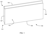
- Gypsum panel 102 also includes an upper interlocking structure 110 disposed at the upper edge 104 thereof. Moreover, a lower interlocking structure 112 is similarly disposed at the lower edge 106 of the gypsum panel 102. Upper interlocking structure 110 and lower interlocking structure 112 are configured to cooperate with neighboring gypsum panels so as to form a building surface. For example, as explained in more detail below, the upper interlocking structure 110 of building surface product 100 may cooperate with the lower interlocking structure of a neighboring building surface product. Likewise, the lower interlocking structure 112 of building surface product 100 may cooperate with the upper interlocking structure of another neighboring building surface product.
- upper and lower refer to one possible installation configuration of the building surface product on a support frame, and are used for relative directions in such a configuration.
- embodiments of the building surface product can be installed in other configurations, such as configurations in which features described as being on an upper side of the product are disposed on the bottom.
- the building surface product of the disclosure can also be installed vertically, such that features described as upper and lower are disposed on the left and/or right.
- the gypsum panel includes at least 1% by weight of reinforcing fibers.
- the gypsum panel includes glass fibers.
- the gypsum panel includes cellulose-based fibers.
- the gypsum panel includes polyethylene, polypropylene or polyester fibers.
- the building surface product include different combinations of the aforementioned fibers in the gypsum panel.
- the lower interlocking structure includes a lower recess formed next to the first lower projection, and the first upper projection is configured to fit in the lower recess of a neighboring building surface product.
- lower interlocking structure 112 includes a lower recess 130 adjacent to first lower projection 124.
- the first upper projection of a neighboring building surface product of similar configuration is configured to fit in the lower recess 130 of interlocking structure 112.
- lower interlocking structure 112 overlaps and cooperates with the corresponding upper interlocking structure of the neighboring building surface product.
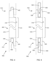
- the lower interlocking structure 412 includes a first lower projection 424 extending downward from body 414 that is adjacent to and coextensive with front face 416 of body 414.
- lower interlocking structure 412 also includes a second lower projection 434 that is adjacent to rear face 418 of body 414.
- a gap is provided between first lower projection 424 and second lower projection 434 to provide a lower recess 430 in the form of a groove.
- the groove 430 provided between first lower projection 424 and second lower projection 434 is configured to receive an upwardly extending projection of a neighboring building surface product.
- the first upper projection is disposed between the front face and the rear face and forms a tongue configured for insertion into the groove of a neighboring building surface product.
- building surface product 400 shown in FIG. 4 , includes an upper interlocking structure 410 that has a first upper projection 422 positioned between the front face 416 and rear face 418 of body 414 of gypsum panel 402.
- First upper projection 422 is specifically configured as a tongue to fit into a groove of a neighboring building surface product.
- the first upper projection 422 of upper interlocking structure 410 is configured so as to cooperate with the recess 430 of lower interlocking structure 412 and be received therein.
- a series of building surface products all having the same configuration as that of building surface product 400 can form a building surface wherein the upper interlocking structure of each gypsum panel fits into the lower interlocking structure of a neighboring gypsum panel.
- the upper interlocking structure includes a second upper projection, wherein an upper groove is disposed between the first upper projection and the second upper projection, and wherein the upper groove and the lower groove are each configured to receive an insert that cooperates with a corresponding groove of a neighboring building surface product.
- Building surface product 500 includes a gypsum panel 502 that has a body 514, which includes a front face 516 and a rear face 518.
- An upper interlocking structure 510 is disposed above body 514 and a lower interlocking structure 512 is disposed below body 514.
- the lower interlocking structure 512 includes a first lower projection 524 extending downward from body 514 that is adjacent to and coextensive with front face 516 and a second lower projection 534 that is adjacent to rear face 518 of body 514.
- a lower recess 530 in the form of a groove is formed between first lower projection 522 and second lower projection 534.
- Upper interlocking structure 510 has a similar configuration as lower interlocking structure 512 and includes a first upper projection 522 extending upward from body 514 that is adjacent to and coextensive with front face 516 and a second upper projection 536 that is adjacent to rear face 518 of body 514.
- An upper recess 538 in the form of a groove is formed between first upper projection 522 and second upper projection 536.
- the upper and lower recesses extend along the entire length of the building surface product, and the insert likewise extends across all or a substantial majority of the building surface product. In other embodiments, the upper and lower recesses are intermittently positioned along the length of the building surface product, and one or more inserts are positioned therein to connect neighboring building surface products.
- the first lower projection has a chamfered edge.
- Building surface product 600 includes a gypsum panel 602 that has a body 614, which includes a front face 616 and a rear face 618.
- An upper interlocking structure 610 is disposed above body 614 and a lower interlocking structure 612 is disposed below body 614.
- Upper interlocking structure 610 includes a first upper projection 622 and lower interlocking structure 612 includes a first lower projection 624.
- the lower end of first lower projection 624 has an angled surface 642 that forms a chamfered edge on first lower projection 624.
- the first lower projection has a rounded edge.
- Building surface product 700 includes a gypsum panel 702 that has a body 714, which includes a front face 716 and a rear face 718.
- An upper interlocking structure 710 is disposed above body 714 and a lower interlocking structure 712 is disposed below body 714.
- Upper interlocking structure 710 includes a first upper projection 722 and lower interlocking structure 712 includes a first lower projection 724.
- the lower end of first lower projection 724 has a convex curved surface 742 that forms a rounded edge on first lower projection 724.
- building surface product 800 includes a gypsum panel 802 that has a body 814, which includes a front face 816 and a rear face 818.
- An upper interlocking structure 810 is disposed above body 814 and a lower interlocking structure 812 is disposed below body 814.
- Upper interlocking structure 810 includes a first upper projection 822 and lower interlocking structure 812 includes a first lower projection 824.
- the lower end of first lower projection 824 has a concave curved surface 842 that forms a rounded edge on first lower projection 824.
- the upper side of the body has a chamfered edge.
- building surface product 600 includes an angled surface extending from front face 616 of body 614 toward first upper projection 622 that forms a chamfered edge 644.
- the upper side of the body has a rounded edge.
- building surface product 700 includes a convex curved surface extending from front face 716 of body 714 toward first upper projection 722 that forms a rounded edge 744.
- building surface product 800 includes a concave curved surface extending from front face 816 toward first upper projection 822 that forms a rounded edge 844.
- building surface product 600 includes chamfered edges 642, 644 toward both the top and bottom of front face 616
- building surface product 700 includes convex rounded edges 742, 744 toward both the top and bottom of front face 716
- building surface product 800 includes concave rounded edges 842, 844 toward both the top and bottom of front face 816
- the building surface product may include a chamfered edge combined with a rounded edge, or a concave rounded edge combined with a convex rounded edge.
- the building surface product includes a straight edge combined with a rounded or chamfered edge. Other combinations and edges are also possible.
- the ends are perpendicular to the upper edge and the lower edge.
- building surface product 100 shown in FIGS. 1 and 2 , has a rectangular shape, and ends 107 and 108 are perpendicular to upper edge 104 and lower edge 106.
- the ends are disposed at an angle to the upper edge and lower edge.
- building surface product 900 shown in FIG.
- first end 907 and second end 908 are disposed at an angle to the upper edge 904 and lower edge 906.
- first end 907 intersects upper edge 904 and lower edge 906 at an angle of about 60 degrees.
- second end 908 intersects upper edge 904 and lower edge 906 at an angle of about 60 degrees.
- the corners of the gypsum panel 902 are obtuse at the upper edge 904 and acute at the lower edge 906, in other embodiments, the corners are obtuse at the lower edge and acute at the upper edge.
- respective corners at the upper edge are obtuse and acute and respective corners at the lower edge are also obtuse and acute, such that the gypsum panel is in the shape of a parallelogram.
- the ends are curved.
- building surface product 1000 shown in FIG. 10 , includes a gypsum panel 1002 that is substantially planar and has an upper edge 1004, a lower edge 1006, a first end 1007, and a second end 1008.
- Each of the first end 1007 and second end 1008 are curved.
- the curved first and second ends 1007, 1008 of building surface product 1000 form rounded corners at lower edge 1006 and sharp corners at upper edge 1004, in other embodiments, the curved ends may form four rounded corners, or configurations of rounded and sharp corners.
- a portion of a first end of the gypsum panel is configured to overlap with a portion of a neighboring building surface product.
- building surface product 1100 shown in FIG. 11 , includes a first lateral projection 1147 at first end 1107 that is adjacent the rear face of gypsum panel 1102 and a second lateral projection 1148 at second end 1108 that is adjacent the front face of gypsum panel 1102.
- the second lateral projection of the neighboring product can overlap the first lateral projection 1147 of building surface product 1100 at first end 1107.
- the second lateral projection 1148 can overlap a corresponding first lateral projection of a neighboring building surface product at the second end 1108 of building surface product 1100.
- the building product further includes a facing that lines at least a portion of the gypsum panel.
- the facing is a paper facing.
- the facing includes reinforcing fibers.
- the facing includes a fiberglass mat.
- the gypsum product of the gypsum panel the building surface product is embedded into the facing.
- the facing surrounds the gypsum panel along its length.
- the facing is formed from two distinct sheets that are wrapped around the gypsum panel. The facing sheets may then be attached to one another to surround the panel. In some embodiments, the facing sheets wrap around the panel along its length. The ends of the panel may then either be left uncovered or the facing sheets may also be folded over the ends.
- the facing includes a reinforcing sheet disposed at the rear face of the gypsum panel.
- the facing includes a robust paper, board, or fiber-reinforced sheet at the rear of the gypsum panel.
- the reinforcing sheet may provide added strength for attaching the building surface product to a support structure.
- the reinforcing sheet is disposed only along the rear face of the gypsum panel.
- the reinforcing sheet may be used in combination with another facing along the front face of the gypsum panel that has a lower tear strength than the reinforcing sheet.
- the front face of the gypsum panel may be free of any facing, while the reinforcing sheet is disposed along the rear face of the gypsum panel.
- a front surface of the building surface product includes a textured surface.
- the front surface of the building surface product is sanded or roughened to provide a surface texture to the front face of the building surface product.
- a coating of a grainy or heterogeneous coating is applied to the front surface of the building surface product.
- building surface product 1200 shown in FIG. 12 , includes a heterogeneous coating applied to portions of the front face 1216 of gypsum panel 1202, which provides the front surface of the building surface product with a textured surface.
- the surface texture of the front face of the building surface product may provide the product with a visual appearance similar to venetian plaster or cast concrete.
- the front face of the body includes grooves along the length of the gypsum panel.
- building surface product 1300 shown in FIG. 13 , includes grooves 1350 that extend across the front surface of the building surface product 1300 parallel to the upper edge 1304 and lower edge 1306.
- the grooves are disposed at regular intervals and provide a gap in the front face of the building surface product that is similar to the gap that is formed where two neighboring building surface products meet. Accordingly, the grooves may help obscure the location of the actual joints between adjacent building surface products.
- the building product further includes fastener holes extending through the gypsum panel.
- building surface product 1300 includes fastener holes 1352 that extend through the first upper projection 1322 of the upper interlocking structure 1310. By placing the fastener holes within a portion of the upper interlocking structure, the fastener holes can be obscured by the first lower projection of a neighboring building surface product that hangs over the first upper projection 1322.
- the building surface product 1300 also includes fastener holes 1352 through the body of the gypsum panel 1302 within grooves 1350. The fastener holes within the grooves are also obscured by their placement within the grooves, where lighting is reduced. In other embodiments, fastener holes are provided alternatively, or in addition, within the lower interlocking structure, or through the entire thickness of the gypsum panel.
- the front surface of the building surface product provides acoustical dampening to the building surface product.
- the front surface of the building surface product includes baffles, ridges, protrusions or other surface features that enhance sound dampening.
- a front surface of the building surface product is painted.
- the building surface product is painted prior to installation on a support structure, such as in a manufacturing facility.
- the building surface product is painted before any mechanical fasteners are used to attach the building surface product to a support structure, such as wall joists.
- the building surface product is painted and is free of mechanical fasteners extending therethrough.
- a width from the upper edge to the lower edge is in a range from 3 inches to 4 feet, e.g., from 4 inches to 2 feet, e.g., from 6 inches to 1 foot.
- a width of the building surface product that is smaller than standard gypsum wallboard products, for example from a few inches up to a foot, can provide an aesthetic that is similar to shiplap.
- the joints between the building surface products form part of the aesthetic of the building surface, and do not need to be covered and hidden. This allows surfaces that are made using the building surface products according to the disclosure to be constructed without the need to cover the joints between the building surface products, which can save considerable time and effort.
- a length from a first end of the gypsum panel to a second end of the gypsum panel is in a range from 1 foot to 20 feet, e.g., from 2 feet to 15 feet, e.g., from 4 feet to 12 feet.
- thickness of the gypsum panel is in a range of 1 ⁇ 4 inch to 3 inches, e.g., from 1 ⁇ 2 inch to 2 inches. Other thicknesses are also possible.
- the disclosure provides a method of making an interlocking building surface product according to any of the above-described embodiments.
- the method includes forming the substantially planar gypsum panel with the upper edge, the lower edge, the upper interlocking structure disposed at the upper edge, the lower interlocking structure disposed at the lower edge, and the two ends.
- a method of the disclosure includes forming gypsum panel 102, shown in FIGS. 1-3 to include the upper edge 104, the lower edge 106, the upper interlocking structure 110 as upper edge 104, the lower interlocking structure 112 at lower edge 106, the first end 107, and the second end 108.
- some embodiments of the method include cutting the general shape of the gypsum panel from a larger sheet of material, and other embodiments include forming the general shape of the gypsum panel directly from a gypsum slurry.
- the upper and lower interlocking structures are machined into the gypsum panel.
- the upper and lower interlocking structures are provided in the gypsum panel when it is formed from a slurry.
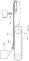
- forming the gypsum panel includes depositing a gypsum slurry over a forming surface and allowing the gypsum slurry to set.
- An embodiment of a method including this stage is shown in FIG. 14 .
- Slurry 1454 is dispensed from a mixer 1456 onto a forming surface 1458 positioned on a conveyor 1460.
- the forming surface 1458 is a flat plane that allows the gypsum slurry 1454 to set in the form of a flat sheet of gypsum.
- the forming surface includes sidewalls that contain the outer sides of the gypsum material as it sets.
- the method further includes the use one or more rollers or dies to further form the gypsum panel into its desired shape, such as a flat sheet.
- the gypsum product passes through one or more ovens to facilitate drying of the gypsum material.
- the forming surface is configured to form a sheet of gypsum material, and the gypsum panel is cut from the sheet of gypsum material.
- the conveyor 1460 moves the gypsum material to a blade 1462 that cuts the gypsum material into the general shape of the gypsum panel.
- the blade can take various forms, for example, a circular saw. In other embodiments, other cutting devices are also possible, such as a laser cutting device, or a water-jet cutting device.
- the width of the sheet of gypsum material is the same as the length of the gypsum panels, and the gypsum panels are cut from the sheet of gypsum material along their upper and lower edges. In other embodiments, the width of the sheet of gypsum material is the same as the width of the gypsum panels, and the gypsum panels are cut from the sheet of gypsum material along their ends.
- the forming surface is configured to form the gypsum panel.
- the forming surface is part of a mold and the shape of the gypsum panel is formed in mold.
- the mold may include boundaries corresponding to the upper edge, the lower edge, the first end and the second end of the gypsum panel.
- the mold may include a cover.
- the upper surface of the mold is open.
- the upper interlocking structure and the lower interlocking structure are machined into the gypsum panel.
- portions of the gypsum panel can be cut, routed or otherwise removed in order to form the upper and lower interlocking structures.
- FIG. 15 Such a method is schematically illustrated in FIG. 15 .
- a CNC machine 1562 is removing a portion of gypsum panel 1502 corresponding to recess 1532 so as to form upper projection 1522 of upper interlocking structure 1510.
- a machine is used to remove other portions of the gypsum panel so as to form the lower interlocking structure.
- material is removed from the front and/or rear face of the gypsum panel, such as is shown in FIG. 15 .
- material is removed from the upper edge and/or lower edge of the gypsum panel.
- material is removed from the ends.
- the forming surface is part of a mold that includes a first portion configured to form the upper interlocking structure and a second portion configured to form the lower interlocking structure.
- a gypsum slurry is dispensed onto forming surface 1658, which is part of a mold 1664.
- the mold 1664 includes a first portion 1666 shaped as a step that occupies a recess of the final gypsum panel 1602 in order to form the first upper projection 1622 of upper interlocking structure 1610.
- a second portion 1668 shaped as an overhang that occupies another recess of the final gypsum panel in order to form the first lower projection 1624 of lower interlocking structure 1612.
- mold 1664 is open at the ends, so as to form a continuous sheet of the gypsum material that includes the upper interlocking structure 1610 and the lower interlocking structure 1612. The sheet of gypsum material is then cut at intervals to create the gypsum panels.
- the mold includes boundaries at the ends and forms a single gypsum panel.
- the method further includes positioning a flexible sheet on the forming surface so as to provide a facing that lines at least a portion of the gypsum panel. In some embodiments, the method further includes positioning a second flexible sheet over the gypsum panel so as to provide the facing that lines another portion of the gypsum panel.
- a flexible sheet is positioned on the forming surface and the gypsum slurry is then dispensed over the flexible sheet. As the gypsum slurry takes the form of the panel, the flexible sheet may be wrapped around the sides of the gypsum panel using rollers or guides. A second flexible sheet may cover the opposing side of the gypsum panel.
- the flexible sheet is paper. In other embodiments, the flexible sheet is a mat, for example a glass fiber mat. In some embodiments, the flexible sheet includes reinforcing fibers, as described above.
- the method further includes connecting the flexible sheet and the second flexible sheet such that the facing surrounds the gypsum panel.
- the flexible sheet may be secured to the second flexible sheet on the opposite side of the panel.
- the flexible sheet forms a facing around the surface of the panel.
- the two flexible sheets may be secured to one another, for example, using a combination of folds and adhesive, as will be appreciated by those of ordinary skill in the art.
- the method further includes forming a surface texture on a front surface of the building surface product.
- forming the surface texture includes spraying a heterogeneous coating on the front surface of the building surface product.
- forming the surface texture includes forming grooves in the front face of the body of the gypsum panel.
- the formation of the grooves may be carried out by removing material from the gypsum panel, such as by using a CNC machine as shown in FIG. 15 .
- the grooves are provided by the forming surface.
- mold 1664 shown in FIG. 16 , includes ridges 1669 that from grooves 1650 in the front face 1616 of the gypsum panel 1602.
- the method further includes providing fastener holes through the gypsum panel.
- fastener holes are drilled through the gypsum panel.
- the fastener holes promote proper placement of mechanical fasteners to secure the building surface product to a support structure. Further, the fastener holes may also assist in maintaining the structural integrity of the gypsum panel.
- the disclosure provides an interlocking building surface system comprising: a plurality of building surface products according to the disclosure secured to a support structure and arranged so as to provide a building surface, wherein the plurality of building surface products includes a first building surface product with an upper interlocking structure coupled to a lower interlocking structure of a second building surface product.
- Building surface system 1790 includes a plurality of building surface products secured to a support structure 1792.
- the support structure 1792 is in the form of a wall frame including a plurality of periodically spaced studs 1794. In other embodiments, the support structure includes other framing elements.
- the support structure is in the form sheathing or panels.
- the building surface products of system 1790 include a first building surface product 1700 and a second building surface product 1701.
- the first building surface product 1700 includes an upper interlocking structure 1712 that is coupled to a lower interlocking structure 1715 of the second building surface product 1701.
- first upper projection of the upper interlocking structure of the first building surface product is covered by a first lower projection of the lower interlocking structure of the second building surface product.
- first lower projection 1725 of lower interlocking structure 1715 of second building surface product 1701 covers first upper projection 1722 of upper interlocking structure 1712 of first building surface product 1701.
- the system further includes mechanical fasteners securing the plurality of building surface products to the support structure.
- mechanical fasteners 1796 such as screws, secure the building surface products to the framing elements 1794 of the support structure 1792.
- the mechanical fasteners pass through fastener holes in the building surface products, while in other embodiments, the fasteners are forced through the gypsum material.
- a first group of the mechanical fasteners extend through the first upper projection of the upper interlocking structure of the first building surface product into the support structure, and the first lower projection of the lower interlocking structure of the second building surface product covers the first group of mechanical fasteners.
- the mechanical fasteners 1796 which attach first building surface product 1700 to support structure 1792 are shown with dotted lines, as they are positioned behind first lower projection 1725 of second building product 1701. Accordingly, because each building surface product overlaps the lower neighboring building surface product, the system may be installed with the mechanical fasteners obscured without the need for any joint compound to cover the mechanical fasteners.
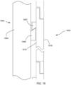
- each of the building surface products includes a cleat disposed on the rear face of the body, and wherein the support structure includes corresponding cleats adapted to engage the cleats of the building surface products.
- Building surface product 1800 includes a body 1814 with a front face 1816 and a rear face 1818.
- a cleat 1897 is attached to the rear face 1818 of body 1814.
- a corresponding cleat 1898 is attached to a framing element 1894 of support structure 1892. Accordingly, building surface product 1800 is secured to support structure 1892 using the cooperative cleats 1897 and 1898.
- the building surface products are attached to the support structure using various other methods.
- the building surface products are attached to the support structure using an adhesive, such as a pressure sensitive adhesive.
- a portion of the second building surface product is attached to a portion of the first building surface product using an adhesive.
- the front surface of the upper projection of the first building surface product is attached to a rear surface of the lower projection of the second building surface product using an adhesive.
- a rear surface of a portion of the second building surface product is attached to a front surface of a portion of the first building surface product using a fastener.
- a fastener for example, in some embodiments the front surface of the upper projection of the first building surface product is attached to a rear surface of the lower projection of the second building surface product using hook and loop fastener.
- the plurality of building surface products have different shapes that are arranged in a pattern, and wherein the first building surface product has a first shape and the second building surface product has a second shape.
- Building surface system is shown in FIG. 19 .
- Building surface system 1990 includes a plurality of building surface products in two configurations. Some of the building surface products are wider at the upper edge than at the lower edge, while some are wider at the lower edge than at the upper edge.
- building surface system 1990 includes a first building surface product 1900 that is wider at the upper edge and a second building surface product 1901 that is wider at the lower edge.
- a joint between the first building surface product and the second building surface product is free of any joint compound.
- the upper interlocking structure and the lower interlocking structure may be configured to have an attractive appearance when the building surface products are adjacent, without the need of any joint compound to hide the joints. Accordingly, the building surface system can be constructed without the need to apply or finish any joint compound, which can save considerable effort in preparing the building surface.
- a front surface of the first building surface product and a front surface of the second building surface product are covered with a layer of paint.
- the paint covers the entire exposed front surface of each building surface product.
- the layer of paint can be applied directly to building surface products from the upper edge to the lower edge and from the first end to the second end.
- the first building surface product is painted a first color and the second building surface product is painted a second color.
- Building surface system 2090 includes a plurality of building surface products in two configurations. Some of the building surface products are wider at the upper edge than at the lower edge, while some are wider at the lower edge than at the upper edge. Further, some of the building surface products are painted a first color while some of the building surface products are painted a second color.
- building surface system 2090 includes a first building surface product 2000 that is painted a first color and a second building surface product 2001 that is painted a second color.
- the disclosure provides a fastenable building surface product including a substantially planar gypsum panel having a first edge, a second edge, and two ends.
- the gypsum panel includes a body comprising a front face, a rear face, and a thickness between the front face and the rear face.
- a first lapping projection extends outward from the body at the second edge and is configured to overlap a portion of a neighboring gypsum panel so as to form a building surface.
- the building surface product also includes a first press-on connector disposed on and attached to the rear face of the body toward the first edge of the gypsum panel. The press-on connector is configured to engage a corresponding second press-on connector.
- the phrase "toward the first edge,” refers to the position of the press-on connector being disposed closer to the first edge than the second edge.
- Building surface product 2100 includes a substantially planar gypsum panel 2102 including a first edge 2104, a second edge 2106, a first end 2107, and a second end 2108.
- the gypsum panel 2102 also includes a body 2114 that has a front face 2116, a rear face 2118 and a thickness between front face 2116 and rear face 2118.
- Building surface product 2100 also includes a first lapping projection 2124 that extends outward from body 2114 at second edge 2106 and that is configured to overlap a portion of a neighboring gypsum panel so as to form a building surface, as described in more detail below.
- a first press-on connector 2170 is disposed on the rear face 2118 of body 2114 near the first edge 2104 of gypsum panel 2102. The press-on connector is configured to engage a corresponding second press-on connector, as described in more detail below.
- the press-on connector and lapping projection are complementary components that allow the fastenable building surface product to have an interlocking engagement with neighboring building surface products while also being modular.
- the building surface product can be positioned so that the lapping projection extends behind a portion of a neighboring panel.
- the first press-on connector can be used to secure the building surface product in place by engaging with a complementary second press-on connector.
- the building surface product can be removable and/or re-installable. For example, the building surface product can be removed from a constructed building surface by initially disengaging the first press-on connector and then removing the lapping projection from behind the neighboring panel.
- first edge of building surface product 2100 is shown at the top of the gypsum panel, and the second edge is shown at the bottom, in other embodiments the first and second edges are reversed.
- the product can be rotated and installed with either edge at the top.
- the building surface products are installed vertically.
- the first press-on connector is a first snap-fit connector and the corresponding second press-on connector is a second snap-fit connector.
- FIG. 22 shows a more detailed view of first press-on connector 2170 of FIG. 21 , in the form of a first snap-fit connector attached to the rear face 2118 of the body 2114 of gypsum panel 2102.
- the first snap-fit connector 2170 is coupled to a corresponding second snap-fit connector 2180 that is secured to a framing member 2194.
- snap-fit is defined as a connection between components where at least one of the components undergoes a deflection as the components are connected. Accordingly, if the connection is detachable, a corresponding deflection is needed in order to disconnect the assembled components.
- Such a snap-fit connection can provide a relatively stable attachment without the need for any additional fasteners.
- the deformation that occurs may be elastic, such that the components return to their original shape after the connection is made or after the components are disconnected. Alternatively, the deformation can be plastic and a permanent connection can be established.
- a snap-fit connection encompasses connections where either or both of the components being attached can undergo the deformation.
- the first snap-fit connector of the building surface product can undergo a deformation as it is attached to the corresponding second snap-fit connector, or the second snap-fit connector can undergo a deflection as it is attached to the first snap-fit connector.
- the first press-on connector can have another configuration, such as a component of a hook and loop fastener, or another recloseable fastener.
- first snap-fit connector includes a connector body and a first flange that extends laterally outward from the connector body and is configured to engage the second snap-fit connector.
- first snap-fit connector 2170 includes a body 2172 with a first flange 2174 extending laterally outward therefrom.
- first flange 2174 extends upward from body 2172.
- second snap-fit connector 2180 has a first flexible hook member 2184 that receives and retains first flange 2174.
- the first snap-fit connector includes a second flange that extends from the connector body in an opposite direction of the first flange and is configured to engage the second snap-fit connector.
- first snap-fit connector 2170 includes a second flange 2175 that extends in an opposite direction from connector body 2172 compared to first flange 2174, specifically, in a downward direction.
- second flange 2175 is configured to be secured by a second flexible hook 2185 of second snap-fit connector 2180.
- first snap-fit connector 2370 includes a connector body 2372 with a first flange 2374 extending laterally outward therefrom and a second flange 2375 extending from the connector body 2372 in a direction opposite first flange 2374.
- second snap-fit connector 2380 has a first flexible hook member 2384 that receives and retains first flange 2374 and a second hook member 2385 that receives and retains second flange 2375. Accordingly, second snap-fit connector, which is attached to framing member 2394, holds the building surface product securely against the framing member by its connection to first snap-fit connector 2370.
- Both first snap-fit connectors 2170 and 2370 have male configurations and second snap-fit connectors 2180 and 2380 have female configurations that receive the first snap-fit connectors.
- the first snap-fit connector has a female configuration that receives the second snap-fit connector.
- the first and second snap-fit connectors may be configured according to different design constraints to have a permanent installation, a re-installable installation, or a removable installation.
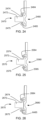
- Various embodiments of such snap-fit connectors are shown in FIGS. 24, 25 and 26 .
- First snap-fit connector 2470 shown in FIG. 24 , provides a permanent connection to second snap-fit connector 2480.
- First snap-fit connector 2470 has a first flange 2474 and a second flange 2475 extending from connector body 2472.
- the first flange 2474 and second flange 2475 respectively cooperate with a first hook 2484 and a second hook 2485 of second snap-fit connector 2480.
- first snap-fit connector 2570 shown in FIG.
- first snap-fit connector 2570 provides a re-installable connection with second snap-fit connector 2580.
- first snap-fit connector 2570 has a first flange 2574 and a second flange 2575 extending from connector body 2572, and cooperates with a second snap-fit connector 2580 that includes a first hook 2584 and a second hook 2585.
- first snap-fit connector 2670 shown in FIG. 26 , has a removable connection with second snap-fit connector 2680.
- first snap-fit connector 2670 has a first flange 2674 and a second flange 2675 extending from connector body 2672. The first flange 2674 and second flange 2675 cooperate with a first hook 2684 and a second hook 2685 of second snap-fit connector 2680.
- the removability or permanence of the connection between the first snap-fit connector and second snap-fit connector is dependent upon the angles and edges of the mating components.
- the outer surfaces of the flanges and hooks are slanted or curved so as to allow the respective components to flex so that a connection of the first snap-fit connector and second snap-fit is possible.
- the inner surfaces and edges have differing shapes to provide various different permanence and removability.
- first snap-fit connector 2470 and the inner surfaces of the hooks 2484 and 2485 of second snap-fit connector 2480 have sharp edges to prevent removal of the first snap-fit connector 2470 from the second snap-fit connector once installed.
- This permanent connection can be advantageous in instances where removal of the building surface products is only permitted in instances where portions of the wall are being destroyed. In some cases, removal of the snap-fit connectors in instances using such a permanent connection requires removal of the second snap-fit connector from the framing members.
- first snap-fit connector 2570 and second snap-fit connector 2580 are configured to allow disconnection of the two components, so that a new building surface product can be installed.
- the inner surfaces of the flanges 2574, 2575 and hooks 2584, 2585 have an appropriate shape to allow disconnection so long as sufficient force is used. In some embodiments, this force is sufficiently high to damage the building surface products, but maintain the function of the second snap-fit connector. Such a configuration allows new building surface products to be installed when one is damaged, but prevents inadvertent or accidental removal upon moderate forces applied to the panels.
- first snap-fit connector 2670 and second snap-fit connector 2680 have inner surfaces of the flanges 2674, 2675 and hooks 2584, 2585 to allow repeated removal and reinsertion. This configuration allows maintenance to be on the building surface, or behind the building surface, without the need to replace any components of the building surface itself.
- a distance between the first snap-fit connector and the first edge is less than 30% of the width of the gypsum panel body, e.g., less than 20%, e.g., less than 10%.
- the first snap-fit connector is disposed in a range of 1 ⁇ 4 inch to 3 inches from the first edge of the building surface product.
- the first snap-fit connector is attached to the gypsum panel using adhesive.
- the adhesive is an organic adhesive, such as a curable glue, a single component epoxy, a two component epoxy, a hot-melt thermoplastic, or a polyurethane resin.
- the adhesive is an inorganic adhesive, such as cement.
- the first snap-fit connector is attached to the gypsum panel using a mechanical fastener, such as a screw.
- the first lapping projection is coextensive with the rear face but thinner than the thickness of the panel.
- the second edge may include a second lapping projection that cooperates with the first lapping projection of a neighboring panel.
- the first lapping projection extends outward from the body in a direction of the plane of the gypsum panel a distance in a range of 1 ⁇ 4 inch to 3 inches, e.g., 3/8 inch to 2.5 inches, e.g., 1 ⁇ 2 inch to 2 inches.
- the first edge includes a folded gypsum edge.
- the second edge also includes a folded gypsum edge.
- the first and second ends also include folded gypsum edges.
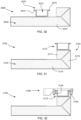
- the folded gypsum edge is a flat fold including a first folded section adhered to the body of the gypsum panel along an angled slit, where the body of the gypsum panel and the first folded section are covered by a continuous facing sheet. Such a folded edge is shown in FIG. 27 .
- Building surface product 2700 includes first snap-fit connector 2770 attached to the rear surface 2718 of gypsum panel 2702.
- the building surface product also includes a first edge 2704 with a folded gypsum edge including a flat fold.
- the folded edge includes a first folded section 2776 that is secured to the body 2714 of gypsum panel 2702 with an adhesive.
- the body 2714 of the gypsum panel 2702 and the first folded section 2776 are covered by a continuous facing sheet 2779 that wraps around the folded edge 2704.
- the folded edge is a corner fold including a first folded section and a second folded section.
- the first folded section is adhered to the body of the gypsum panel along a first angled slit and the second folded section is adhered to the first folded section along a second angled slit.
- the body of the gypsum panel, the first folded section, and the second folded section are all covered by a continuous facing sheet.
- Such a folded edge is shown in FIG. 28 .
- Building surface product 2800 includes first snap-fit connector 2870 attached to the rear surface 2818 of gypsum panel 2802.
- the building surface product also includes a first edge 2804 with a folded gypsum edge including a corner fold.
- the folded edge includes a first folded section 2876 that is secured to the body 2814 of gypsum panel 2802 along an angled slit using an adhesive. Further, a second folded section 2877 is secured to the first folded section 2876 along another angled slit by adhesive.
- the body 2814 of the gypsum panel 2802, the first folded section 2886, and the second folded section 2877 are all covered by a continuous facing sheet 2879 that wraps around the folded edge 2804.
- the second folded section is adhered to the first snap-fit connector.
- second folded edge 2877 is attached to first snap-fit connector 2870 with an adhesive.
- the first snap-fit connector includes a base extending outward from the connector body, wherein the base is adhered to the body of the gypsum panel, and wherein the second folded section overlaps the base of the first snap-fit connector.
- Building surface product 2900 includes first snap-fit connector 2970 attached to the rear surface 2918 of gypsum panel 2902.
- First snap-fit connector 2970 includes a base 2978 extending outward from connector body 2972.
- the building surface product also includes a first edge 2904 with a folded gypsum edge including a corner fold.
- the folded edge includes a first folded section 2976 that is secured to the body 2914 of gypsum panel 2902 along an angled slit using an adhesive. Further, a second folded section 2977 is secured to the first folded section 2976 along another angled slit by adhesive. Moreover, second folded edge 2977 overlaps base 2978 of first snap-fit connector 2970. Furthermore, the body 2914 of the gypsum panel 2902, the first folded section 2986, and the second folded section 2977 are all covered by a continuous facing sheet 2979 that wraps around the folded edge 2904.
- the connector body of the first snap-fit connector is solid.
- connector body 2472 of first snap-fit connector 2470, shown in FIG. 24 is a solid body.
- the connector body of the first snap-fit connector is hollow.
- Building surface product 3000 includes a first snap-fit connector 3070 includes a hollow connector body 3072 having a "U" shaped cross-section and including first flange 3074 and second flange 3075 extending outward from the upper ends of connector body 3072.
- the snap-fit connector has a standard rail configuration, such as DIN rail.
- the rail can be formed of metal, such as cold-rolled steel or a polymer, such as an extruded plastic.
- the snap-fit connector is disposed on the body of the gypsum panel.
- snap-fit connector 3070 is disposed on the body 3014 of gypsum panel 3002.
- the snap-fit connector is disposed on the folded edge of the gypsum panel.
- building surface product 3100 shown in FIG. 31 , includes a gypsum panel 3102 with a folded edge 3104 having a first folded section 3176 and a second folded section 3177.
- First snap-fit connector 3170 is disposed on top of the second folded section 3177 of folded edge 3104.
- FIG. 32 shows the first snap-fit connector 3170 coupled to a second snap-fit connector 3180 using a first hook 3184 and a second hook 3185 that secure the respective flanges of first snap-fit connector.
- the gypsum panel comprises a reinforced gypsum material.
- the gypsum panel includes at least 1% by weight polymer.
- the polymer includes starch and/or polyvinyl acetate.
- the gypsum panel includes at least 1% by weight of reinforcing fibers.
- the gypsum panel includes glass fibers.
- the gypsum panel includes cellulose-based fibers.
- the gypsum panel includes polyethylene, polypropylene or polyester fibers.
- the building surface product include different combinations of the aforementioned fibers in the gypsum panel.
- the gypsum panel includes one or more additives, such as biocides, hydrophobic additives, and fire resistance additives.
- the ends are perpendicular to the upper edge and the lower edge. In other embodiments, the ends are disposed at an angle to the upper edge and lower edge. For example, in some embodiments of the fastenable building surface product, the ends are at an angle in a range of 30 degrees to 80 degrees from the upper edge or lower edge. Further, in some embodiments of the fastenable building surface product, the ends are curved.
- a portion of a first end of the gypsum panel is configured to overlap with a portion of a neighboring building surface product.
- the fastenable building surface product further includes a facing that lines at least a portion of the gypsum panel.
- the facing is a paper facing.
- the facing includes reinforcing fibers.
- the facing includes a fiberglass mat.
- the gypsum product of the gypsum panel the building surface product is embedded into the facing.
- a front surface of the building surface product includes a textured surface.
- the front surface of the building surface product is sanded or roughened to provide a surface texture to the front face of the building surface product.
- a coating of a grainy or heterogeneous coating is applied to the front surface of the building surface product.
- the surface texture of the front face of the building surface product may provide the product with a visual appearance similar to venetian plaster or cast concrete, for example.
- the front face of the body includes grooves along the length of the gypsum panel.
- the grooves are disposed at regular intervals and provide a gap in the front face of the building surface product that is similar to the gap that is formed where two neighboring building surface products meet. Accordingly, the grooves may help obscure the location of the actual joints between adjacent building surface products.
- the front surface of the building surface product provides acoustical dampening to the building surface product.
- the front surface of the building surface product includes baffles, ridges, protrusions or other surface features that enhance sound dampening.
- a front surface of the building surface product is painted.
- the building surface product is painted prior to installation on a support structure, such as in a manufacturing facility.
- a width from the upper edge to the lower edge is in a range from 3 inches to 4 feet, e.g., from 4 inches to 2 feet, e.g., from 6 inches to 1 foot.
- a width of the building surface product that is smaller than standard gypsum wallboard products, for example from a few inches up to a foot, can provide an aesthetic that is similar to shiplap. As are result, the joints between the building surface products form part of the aesthetic of the building surface, and do not need to be covered and hidden. This allows surfaces that are made using the building surface products according to the disclosure to be constructed without the need to cover the joints between the building surface products, which can save considerable time and effort.
- a length from a first end of the gypsum panel to a second end of the gypsum panel is in a range from 1 foot to 20 feet, e.g., from 2 feet to 15 feet, e.g., from 4 feet to 12 feet.
- the thickness of the gypsum panel is in a range of 1 ⁇ 4 inch to 3 inches, e.g., from 1 ⁇ 2 inch to 2 inches. Other thicknesses are also possible
- the disclosure provides a method of making a fastenable building surface product according to the disclosure.
- the method includes forming the substantially planar gypsum panel with the first edge, the second edge, the first lapping projection extending outward from the body at the second edge, and the two ends.
- the method also includes attaching the first press-on connector to the rear face of the body of the gypsum panel.
- a method of the disclosure includes forming gypsum panel 2102, shown in FIGS. 21 and 22 to include the upper edge 2104, the lower edge 2106, the first lapping projection extending from the body 2114 of gypsum panel 2102 at second edge 2106, the first end 2107, and the second end 2108.
- Press-on connector 2170 is then attached to the rear face 2118 of gypsum panel 2102.
- some embodiments of the method include cutting the general shape of the gypsum panel from a larger sheet of material, and other embodiments include forming the general shape of the gypsum panel directly from a gypsum slurry.
- the lapping projection is attached to the rear face of the gypsum panel. In other embodiments the lapping projection is machined into the gypsum panel. Still in other embodiments, the lapping projection is provided in the gypsum panel when it is formed from a slurry.
- the method further includes positioning a second flexible sheet over the gypsum panel so as to provide a facing that lines another portion of the gypsum panel.
- the method further includes forming the first edge of the gypsum panel as a folded edge with a flat fold by: cutting a first notch in the sheet of gypsum material so as to form a first folded section adjacent to the body of the gypsum panel, folding the first folded section toward the body of the gypsum panel so as to close the notch, and adhering the first folded section to the body of the gypsum panel.
- first edge 2704 shown in FIG. 27 , is formed by cutting a notch in the gypsum material to form first folded section 2776 next to the body 2714 of gypsum panel 2702.
- First folded section 2776 is then folded toward body 2714 so as to close the notch, such that first folded section 2776 abuts body 2714.
- An adhesive is provided between first folded section 2776 and body 2714 to hold the folded edge closed.
- the method further includes forming the first edge of the gypsum panel as a folded edge with a corner fold by: cutting a first notch in the sheet of gypsum material so as to form a first folded section adjacent to the body of the gypsum panel, cutting a second notch in the sheet of gypsum material so as to form a second folded section adjacent to the first folded section, folding the second folded section toward the first folded section so as to close the second notch, adhering the second folded section to the first folded section, folding the first folded section toward the body of the gypsum panel so as to close the first notch and to place the second folded section over the body of the gypsum panel, and adhering the first folded section to the body of the gypsum panel.
- first edge 2804 is formed by cutting a first notch in the gypsum material to form first folded section 2876 adjacent body 2814 of gypsum panel 2802, and cutting a second notch in the gypsum material to form a second folded section 2877 adjacent to the first folded section 2876.
- the first folded section 2876 is folded toward second folded section 2877 and adhered thereto.
- the second folded section 2877 is then folded toward first folded section 2876 in order to close the second notch and the two sections are attached with adhesive.
- the first folded section 2876 is then folded toward the body 2814 to close the first notch and the first folded section 2876 is attached to the body with more adhesive.
- the first press-on connector is a snap-fit connector
- the method further includes adhering the second folded section to the snap-fit connector.
- second folded section 2877 is attached to first snap-fit connector 2870 using adhesive.
- the snap-fit connector includes a base extending outward from the connector body, and the method further includes folding the second folded section over the base of the snap-fit connector so as to place the base of the snap-fit connector between the second folded section and the body of the gypsum panel.
- second folded section 2977 is folded over the base 2978 of first snap-fit connector 2970 in order to place the base 2978 between second folded section 2977 and body 2914 of gypsum panel 2902.
- the method includes adhering the first snap-fit connector onto the folded edge of the gypsum panel.
- the first snap-fit connector 3170 is adhered to the second folded section 3177 of folded edge 3104 of gypsum panel 3102.
- the first lapping projection is machined into the gypsum panel.
- the first lapping projection is formed in the gypsum panel using a CNC machine, as shown in FIG. 15 .
- the first lapping projection is adhered to the body of the gypsum panel.
- a layer of adhesive is placed on an inside surface of the first lapping projection, and the first lapping projection is attached to the rear face of the gypsum panel.
- the adhesive is an organic adhesive, such as a curable glue, a single component epoxy, a two component epoxy, a hot-melt thermoplastic, or a polyurethane resin.
- the adhesive is an inorganic adhesive, such as cement.
- the method further includes forming a surface texture on a front surface of the building surface product.
- forming the surface texture includes spraying a heterogeneous coating on the front surface of the building surface product.
- forming the surface texture includes forming grooves in the front face of the body of the gypsum panel. For example, the formation of the grooves may be carried out by removing material from the gypsum panel, such as by using a CNC machine as shown in FIG. 15 . In other embodiments, the grooves are provided by the forming surface.
- the disclosure provides a fastenable building surface system including a support structure, a plurality of second press-on connectors disposed on a front side of the support structure, and a plurality of fastenable building surface products according to the disclosure secured to the support structure and arranged so as to provide a building surface.
- the first press-on connector of each building surface product is coupled to at least one of the second press-on connectors. Further, the first edge of the gypsum panel of each building surface product overlaps the first lapping projection of a neighboring building surface product.
- Building surface system 2190 includes a plurality of building surface products 2100, such as that shown in FIGS.
- the support structure 2192 is in the form of a wall frame including a plurality of periodically spaced studs 2194. In other embodiments, the support structure includes other framing elements. Further, in some embodiments, the support structure is in the form of sheathing or panels.
- Each of the building surface products 2100 of system 2190 include a first building surface product 2101 and a second building surface product 2103.
- the first building surface product 2101 includes a first press-on connector 2170 that is coupled to a plurality of second press-on connectors 2180 attached to the support structure 2192.
- the first and second press-on connectors 2170 and 2180 of first building surface product 2101 are positioned behind the gypsum panel 2102 and therefore are schematically depicted using dashed lines.
- the first building surface product 2101 also includes a first lapping projection 2124 that is configured to be positioned behind second building surface product 2103.
- Second building surface product 2103 is presented as it is being installed.
- Second building surface product 2103 includes first lapping projection 2124 that is being inserted behind the gypsum panel of a lowering neighbor building surface product.
- second building surface product 2103 includes a first press-on connector 2170 that is prepared to connect to a plurality of second press-on connectors 2180.
- first press-on connectors are first snap-fit connectors and the second press-on connectors are second snap-fit connectors.
- first press-on connectors 2170 are second press-on connectors 2180 are both complementary snap-fit connectors.
- each of the first snap-fit connectors includes a connector body and a first flange that extends laterally outward from the connector body, and each of the second snap-fit connectors includes a clip having a first flexible hook configured to engage the first flange.
- first snap-fit connector 2170 includes a body 2172 with a first flange 2174 extending laterally outward therefrom, and second snap-fit connector 2180 is formed as a clip and has a first flexible hook member 2184 that receives and retains first flange 2174.
- each first flexible hook includes an outer angled ramp surface configured to deflect the flexible hook as the first snap-fit connector is inserted into the clip.
- first flexible hook 2184 of second snap-fit connector includes an outer surface that has the shape of an angled ramp so as to allow the insertion of first snap-fit connector to push the flexible hook laterally as the first snap-fit connector is inserted into the clip.
- each first flexible hook includes a sharp inner edge configured to inhibit removal of the first snap-fit connector from the clip of the second snap-fit connector.
- flexible hooks 2484 and 2485 of second snap-fit connector 2480, shown in FIG. 24 have sharp inner edges. The sharp inner edge of each flexible hook 2484 and 2485 promote a permanent connection of first snap-fit connector 2470 and second snap-fit connector 2480 when they are attached to one another.
- each first flexible hook includes an angled inner edge configured to deflect the flexible hook as the first snap-fit connector is removed from the clip.
- flexible hooks 2684 and 2685 of second snap-fit connector 2680 shown in FIG. 26 have angled inner edges, which promote a removable connection of the first and second snap-fit connectors.
- the angled inner edges of flexible hooks 2684 and 2685 allow the hooks to be flexed outward so that first snap-fit connector 2670 can be removed from the second snap-fit connector 2680.
- each of the second snap-fit connectors is secured to the support structure with at least one mechanical fastener.
- the second snap-fit connectors are coupled to framing members or a surface of the support structure using screws or nails.
- the second snap-fit connectors are secured to the support structure using an adhesive.
- each of the second snap fit connectors includes a support platform, and wherein each support platform provides a contact surface for a respective first lapping projection of a building surface product.
- second snap fit connector 2180 as shown in FIG. 22 , includes a platform 2186. The platform serves as contact surface for the first lapping projection of the neighboring building surface product.
- the plurality of building surface products have different shapes that are arranged in a pattern, and wherein the first building surface product has a first shape and the second building surface product has a second shape.
- a building surface system with such a construction is shown in FIG. 19 , and described above.
- a joint between the first building surface product and the second building surface product is free of any joint compound.
- the first and second edges of the building surface products may be configured to have an attractive appearance when the building surface products are adjacent, without the need of any joint compound to hide the joints. Accordingly, the building surface system can be constructed without the need to apply or finish any joint compound, which can save considerable effort in preparing the building surface.
- a front surface of each of the building surface products is covered with a layer of paint.
- a first of the building surface products is painted a first color and a second of the building surface products is painted a second color.
- a building surface system with such a construction is shown in FIG. 20 , and described above.
Landscapes
- Engineering & Computer Science (AREA)
- Architecture (AREA)
- Civil Engineering (AREA)
- Structural Engineering (AREA)
- Panels For Use In Building Construction (AREA)
- Finishing Walls (AREA)
Description
- This application claims the benefit of priority of
U.S. Provisional Patent Application 62/875,238, filed July 17, 2019 - The present disclosure relates generally to building surface products, for example, panels suitable for forming a building surface. The present disclosure relates more particularly to building surface products having overlapped edges.
- Prefabricated panels, for example gypsum wallboards that are commonly referred to as drywall, are often used to construct building surfaces. The wallboards are attached to a supporting structure, such as the joists of a wall frame. Once the wallboards are hung on the supporting structure, the wall is finished using joint compound or another material to create a smooth surface. The wall may then be painted or covered with wall paper.
- Gypsum wallboards are advantageous for use as a building surface for various reasons. Such wallboards are incredibly durable, have excellent fire resistance, are easily repaired, and are easy to mount on a supporting structure. Typically, mounting gypsum wallboard panels only requires attaching the wallboards to an underlying supporting structure using mechanical fasteners, such as screws.
- While the mounting of gypsum wallboards is relatively easy, most wallboard panels are finished by covering the joints between the panels and the fasteners in order to create a smooth surface. The wallboards are then painted or covered with wall paper to create a pleasing aesthetic. The process of finishing the building surface is time consuming, as each application of joint compound or paint should be dried before the subsequent step can be performed. Moreover, the finishing steps require uncommon skills. Accordingly, the present inventors have determined that a building surface formed of gypsum-based products that are constructed without requiring timely finishing would be attractive to both builders and customers.
-
EP2898157A1 discloses a building board for mounting on a support structure including a set of studs (150). The building board comprising a framing element (101 essentially shaped as a rectangular cuboid including two opposite main sides having relatively large delimitation surfaces and four edge sides having relatively small delimitation surfaces. A first type of snap-in means (A1) are arranged along a first edge side and a second type of snap-in means (A2) are arranged along a second edge sides opposite to said first edge side. The snap-in means of the first type (A1) is, after mounting of the building board against the support structure, configured to receive a snap-in means of the second type (A2) of another building board so that this building board is connected to the mounted building board. Either the snap-in means of said first or second type (A1, A2) includes a groove (111S; 112S) for receiving at least one clamping element (151S) for fixing and holding the first and the second building boards against a stud (150) of the support structure. -
US2005/193666A1 discloses cover pads for use on upright walls, wherein the pad provides an improved internal support which is of simplified construction, for example the center support and the surrounding frame being made of a one-piece monolithic support structure which permits a flexible covering to be attached to the center support and the exterior side surfaces of the edge frame while the covering and support structure are in a flat and planar condition, following which the edge frame is folded and secured into position around the center support. The internal support structure for the pad, when in a flat condition, has voids at the corners so that the covering can be tucked into the corners prior to the edge frame being folded into its frame-defining position. - In one aspect, the invention provides a fastenable building surface product comprising:
- a substantially planar gypsum panel having a first edge, a second edge, and two ends, wherein the gypsum panel includes:
- a body comprising a front face, a rear face, and a thickness between the front face and the rear face, and
- a first lapping projection extending outward from the body at the second edge, the first lapping projection being configured to overlap a portion of a neighboring gypsum panel so as to form a building surface; and
- a first press-on connector disposed on and attached to the rear face of the body toward the first edge of the gypsum panel, the press-on connector being configured to engage a corresponding second press-on connector.
- In another aspect, the invention provides a method of making a building surface product, in accordance with
claim 11. - Additional aspects of the invention are subject-matter of the dependent claims and will be evident from the following embodiments of the invention.
- The accompanying drawings are included to provide a further understanding of the methods and devices of the disclosure, and are incorporated in and constitute a part of this specification. The drawings are not necessarily to scale, and sizes of various elements may be distorted for clarity. The drawings illustrate one or more embodiment(s) of the disclosure, and together with the description serve to explain the principles and operation of the invention.
-
FIG. 1 is a schematic perspective view of an interlocking building surface product not according to the claimed invention; -
FIG. 2 is a side view of the building surface product ofFIG. 1 ; -
FIG. 3 is another side view of the building surface product ofFIG. 1 coupled to neighboring building surface products; -
FIG. 4 is side view of an interlocking building surface product not according to the claimed invention; -
FIG. 5 is a side view of an interlocking building surface product not according to the claimed invention; -
FIG. 6 is a side view of an interlocking building surface product not according to the claimed invention; -
FIG. 7 is a side view of an interlocking building surface product not according to the claimed invention; -
FIG. 8 is a side view of an interlocking building surface product not according to the claimed invention; -
FIG. 9 is a perspective view of an interlocking building surface product not according to the claimed invention; -
FIG. 10 is a perspective view of an interlocking building surface product not according to the claimed invention; -
FIG. 11 is a perspective view of an interlocking building surface product not according to the claimed invention; -
FIG. 12 is a perspective view of an interlocking building surface product not according to the claimed invention; -
FIG. 13 is a perspective view of an interlocking building surface product not according to the claimed invention; -
FIG. 14 is a schematic side view of an apparatus used in a method of making a building surface product according to an embodiment of the disclosure; -
FIG. 15 is a schematic side view of another tool used in a method of making a building surface product according to an embodiment of the disclosure; -
FIG. 16 is a schematic front view of a mold used in a method of making a building surface product according to an embodiment of the disclosure; -
FIG. 17 is a schematic perspective view of a portion of a building surface system not according to the claimed invention; -
FIG. 18 is a schematic side view of an interlocking building surface product not according to the claimed invention; -
FIG. 19 is a schematic front view of a portion of an interlocking building surface system not according to the claimed invention; -
FIG. 20 is a schematic front view of a portion of an interlocking building surface system not according to the claimed invention; -
FIG. 21 is a schematic perspective view of an fastenable building surface product according to an embodiment of the invention; -
FIG. 22 is a schematic detailed side view of snap-fit connectors according to an embodiment of the invention; -
FIG. 23 is a schematic detailed side view of snap-fit connectors according to another embodiment of the invention; -
FIG. 24 is a schematic detailed side view of snap-fit connectors according to yet another embodiment of the invention; -
FIG. 25 is a schematic detailed side view of snap-fit connectors according to another embodiment of the invention; -
FIG. 26 is a schematic detailed side view of snap-fit connectors according to still another embodiment of the invention; -
FIG. 27 is a schematic detailed side view of an edge of a building surface product according to an embodiment of the invention; -
FIG. 28 is a schematic detailed side view of an edge of a building surface product according to another embodiment of the invention; -
FIG. 29 is a schematic detailed side view of an edge of a building surface product according to yet another embodiment of the invention; -
FIG. 30 is a schematic detailed side view of an edge of a building surface product according to another embodiment of the invention; -
FIG. 31 is a schematic detailed side view of an edge of a building surface product according to yet another embodiment of the invention; -
FIG. 32 is a schematic detailed side view of an edge of a building surface product according to yet another embodiment of the invention; and -
FIG. 33 is a schematic perspective view of a fastenable building surface system according to an embodiment of the invention. - As described above, the present inventors have noted that conventional building surfaces formed of gypsum products involve extensive finishing to meet customer expectations. The present inventors have determined that a building surface formed of gypsum-based products that are constructed without requiring timely finishing would be attractive to both builders and customers.
- Accordingly, one aspect of the disclosure not according to the claimed invention is an interlocking building surface product including a substantially planar gypsum panel having an upper edge, a lower edge, and two ends. The gypsum panel includes a body comprising a front face, a rear face, and a thickness between the front face and the rear face. An upper interlocking structure is disposed at the upper edge of the gypsum panel and a lower interlocking structure is disposed at the lower edge of the gypsum panel. The upper interlocking structure includes a first upper projection that extends upward from the body of the gypsum panel and has a thickness that is smaller than the thickness of the body. Likewise, the lower interlocking structure includes a first lower projection that extends downward from the body and has a thickness that is smaller than the thickness of the body. The upper interlocking structure and the lower interlocking structure are configured to cooperate with neighboring gypsum panels so as to form a building surface.
- Such a building surface product is shown in perspective view in
FIG. 1 . Buildingsurface product 100 includes agypsum panel 102 that is substantially planar and has anupper edge 104, alower edge 106, afirst end 107, and asecond end 108. The term planar, as used herein, refers to a panel in which a plane can pass through the entirety of the panel from one end to the other. Thus, the surfaces of a planar panel are not required to be entirely flat, so long as the shape of the panel follows a plane. The term substantially planar refers to a shape that bows along its length or width to an extent of no more than 5 degrees. In some embodiments of the present disclosure, the building surface product is substantially planar, and in some embodiments the building surface product is planar. Still, in other embodiments, the building surface curves along its length to a greater extent than 5 degrees. -
Gypsum panel 102 also includes anupper interlocking structure 110 disposed at theupper edge 104 thereof. Moreover, alower interlocking structure 112 is similarly disposed at thelower edge 106 of thegypsum panel 102.Upper interlocking structure 110 andlower interlocking structure 112 are configured to cooperate with neighboring gypsum panels so as to form a building surface. For example, as explained in more detail below, theupper interlocking structure 110 of buildingsurface product 100 may cooperate with the lower interlocking structure of a neighboring building surface product. Likewise, thelower interlocking structure 112 of buildingsurface product 100 may cooperate with the upper interlocking structure of another neighboring building surface product. The terms upper and lower, as used herein, refer to one possible installation configuration of the building surface product on a support frame, and are used for relative directions in such a configuration. However, embodiments of the building surface product can be installed in other configurations, such as configurations in which features described as being on an upper side of the product are disposed on the bottom. Likewise, the building surface product of the disclosure can also be installed vertically, such that features described as upper and lower are disposed on the left and/or right. - As shown in the side view of
building surface product 100, inFIG. 2 ,gypsum panel 102 includes abody 114 having afront face 116 and arear face 118.Further gypsum panel 102 has athickness 120 that extends fromfront face 116 ofbody 114 torear face 118 ofbody 114. In some embodiments, the thickness of the body is equal to the thickness of the building surface product as a whole, in other embodiments, the building surface product is thicker than the thickness of the body.Upper interlocking structure 110 includes a firstupper projection 122 that extends upward frombody 114 ofgypsum panel 102. Similarly,lower interlocking structure 112 includes a firstlower projection 124 that extends downward frombody 114. The thickness of each projection is smaller thanthickness 120 of thebody 114 ofgypsum panel 102. In particular, thethickness 126 of firstupper projection 122 is smaller thanthickness 120 ofbody 114 andthickness 128 of firstlower projection 124 is smaller thanthickness 120. In some embodiments, the combined thickness of the first upper projection and the first lower projection is no greater than the thickness of the body of the gypsum panel. This allows the first upper projection of one panel and the first lower projection of another panel to overlap while the body of the two panels are coplanar, as described in more detail below. - In certain embodiments of the interlocking building surface product as otherwise described herein, the gypsum panel comprises a reinforced gypsum material. In some embodiments, the gypsum panel includes at least 1% by weight polymer. Reference to the weight percentage of a component of the gypsum panel, as used herein, refers to the weight after the gypsum has set. In certain embodiments, the polymer includes starch and/or polyvinyl acetate.
- In certain embodiments of the interlocking building surface product as otherwise described herein, the gypsum panel includes at least 1% by weight of reinforcing fibers. For example, in some embodiments, the gypsum panel includes glass fibers. Further, in some embodiments, the gypsum panel includes cellulose-based fibers. Moreover, in some embodiments, the gypsum panel includes polyethylene, polypropylene or polyester fibers. Various embodiments of the building surface product include different combinations of the aforementioned fibers in the gypsum panel.
- In some embodiments, the gypsum panel includes one or more additives, such as biocides, hydrophobic additives, and fire resistance additives.
- In certain embodiments of the interlocking building surface product as otherwise described herein, the first lower projection is coextensive with the front face of the body. For example, in building
surface product 100 firstlower projection 124 extends downward frombody 114 at thefront face 116 ofbody 114, such that the front surface of firstlower projection 124 is flush withfront face 116. Accordingly, thelower projection 124 forms an extension ofbody 114 alongfront face 116, forming a continuous surface betweenbody 114 and firstlower projection 124. - In certain embodiments of the interlocking building surface product as otherwise described herein, the lower interlocking structure includes a lower recess formed next to the first lower projection, and the first upper projection is configured to fit in the lower recess of a neighboring building surface product. For example, in building
surface product 100,lower interlocking structure 112 includes alower recess 130 adjacent to firstlower projection 124. As shown inFIG. 3 , the first upper projection of a neighboring building surface product of similar configuration is configured to fit in thelower recess 130 of interlockingstructure 112. As a result,lower interlocking structure 112 overlaps and cooperates with the corresponding upper interlocking structure of the neighboring building surface product. - In certain embodiments of the interlocking building surface product as otherwise described herein, the first upper projection is coextensive with the rear face of the body. For example, as shown in
FIG. 2 , the first upper projection extends upward frombody 114 at therear face 118 ofbody 114, such that the rear surface of firstupper projection 122 is flush withrear face 118. This allowsupper projection 122 andrear face 118 ofbody 114 form flat surface for bracing against a support frame, as explained in more detail below. In particular, theupper projection 122 andrear face 118 are coextensive and form a continuous surface betweenbody 114 and firstupper projection 122. - In some embodiments of the interlocking building surface product as otherwise described herein, the
upper interlocking structure 110 includes an upper recess formed next to the first upper projection, and the first lower projection is configured to fit into the upper recess of a neighboring building surface product. For example, in buildingsurface product 100,upper interlocking structure 110 includes anupper recess 132, similar tolower recess 130, that is adjacent to firstupper projection 122. As shown inFIG. 3 , the first lower projection of a neighboring building surface product is configured to fit in theupper recess 132 of interlockingstructure 110. As a result,upper interlocking structure 110 overlaps and cooperates with the corresponding lower interlocking structure of the neighboring building surface product. - In certain embodiments of the interlocking building surface product as otherwise described herein, the lower interlocking structure includes a second lower projection adjacent the rear face of the body, and wherein the lower recess is in the form of a lower groove disposed between the first lower projection and the second lower projection. An example of such a building surface product is shown in
FIG. 4 . Buildingsurface product 400 includes agypsum panel 402 that has abody 414, which includes afront face 416 and arear face 418. Anupper interlocking structure 410 is disposed abovebody 414 and alower interlocking structure 412 is disposed belowbody 414. Thelower interlocking structure 412 includes a firstlower projection 424 extending downward frombody 414 that is adjacent to and coextensive withfront face 416 ofbody 414. In addition,lower interlocking structure 412 also includes a secondlower projection 434 that is adjacent torear face 418 ofbody 414. A gap is provided between firstlower projection 424 and secondlower projection 434 to provide alower recess 430 in the form of a groove. In order to interlock with a neighboring building surface product, thegroove 430 provided between firstlower projection 424 and secondlower projection 434 is configured to receive an upwardly extending projection of a neighboring building surface product. - In certain embodiments of the interlocking building surface product as otherwise described herein, the first upper projection is disposed between the front face and the rear face and forms a tongue configured for insertion into the groove of a neighboring building surface product. For example, building
surface product 400, shown inFIG. 4 , includes anupper interlocking structure 410 that has a firstupper projection 422 positioned between thefront face 416 andrear face 418 ofbody 414 ofgypsum panel 402. Firstupper projection 422 is specifically configured as a tongue to fit into a groove of a neighboring building surface product. In particular, the firstupper projection 422 ofupper interlocking structure 410 is configured so as to cooperate with therecess 430 oflower interlocking structure 412 and be received therein. Thus, a series of building surface products all having the same configuration as that of buildingsurface product 400 can form a building surface wherein the upper interlocking structure of each gypsum panel fits into the lower interlocking structure of a neighboring gypsum panel. - In certain embodiments of the interlocking building surface product as otherwise described herein, the upper interlocking structure includes a second upper projection, wherein an upper groove is disposed between the first upper projection and the second upper projection, and wherein the upper groove and the lower groove are each configured to receive an insert that cooperates with a corresponding groove of a neighboring building surface product. Such a building surface product is shown in
FIG. 5 . Buildingsurface product 500 includes agypsum panel 502 that has abody 514, which includes afront face 516 and arear face 518. Anupper interlocking structure 510 is disposed abovebody 514 and alower interlocking structure 512 is disposed belowbody 514. Thelower interlocking structure 512 includes a firstlower projection 524 extending downward frombody 514 that is adjacent to and coextensive withfront face 516 and a secondlower projection 534 that is adjacent torear face 518 ofbody 514. Alower recess 530 in the form of a groove is formed between firstlower projection 522 and secondlower projection 534.Upper interlocking structure 510 has a similar configuration aslower interlocking structure 512 and includes a firstupper projection 522 extending upward frombody 514 that is adjacent to and coextensive withfront face 516 and a secondupper projection 536 that is adjacent torear face 518 ofbody 514. Anupper recess 538 in the form of a groove is formed between firstupper projection 522 and secondupper projection 536. - Each of the
upper interlocking structure 510 andlower interlocking structure 512 are configured to receive an insert, such asinsert 540, in the respectiveupper recess 538 andlower recess 530. Accordingly, neighboring building surface products having a configuration similar to that of buildingsurface product 500 connect to one another using the upper interlocking structure and lower interlocking structure via an insert disposed in the adjacent recesses. In some embodiments, the recesses of adjacent building surface products are aligned such that the insert may be a straight plank. In other embodiments, the recesses are offset or have complex shapes, and the insert has a corresponding shape configured to be received in the recesses of two neighboring building surface products. In some embodiments, the upper and lower recesses extend along the entire length of the building surface product, and the insert likewise extends across all or a substantial majority of the building surface product. In other embodiments, the upper and lower recesses are intermittently positioned along the length of the building surface product, and one or more inserts are positioned therein to connect neighboring building surface products. - In certain embodiments of the interlocking building surface product as otherwise described herein, the first lower projection has a chamfered edge. For example, such a building surface product is shown in
FIG. 6 . Buildingsurface product 600 includes agypsum panel 602 that has abody 614, which includes afront face 616 and arear face 618. Anupper interlocking structure 610 is disposed abovebody 614 and alower interlocking structure 612 is disposed belowbody 614.Upper interlocking structure 610 includes a firstupper projection 622 andlower interlocking structure 612 includes a firstlower projection 624. The lower end of firstlower projection 624 has anangled surface 642 that forms a chamfered edge on firstlower projection 624. - In certain embodiments of the interlocking building surface product as otherwise described herein, the first lower projection has a rounded edge. For example, such a building surface product is shown in
FIG. 7 and FIG. 8 . Buildingsurface product 700 includes agypsum panel 702 that has abody 714, which includes afront face 716 and arear face 718. Anupper interlocking structure 710 is disposed abovebody 714 and alower interlocking structure 712 is disposed belowbody 714.Upper interlocking structure 710 includes a firstupper projection 722 andlower interlocking structure 712 includes a firstlower projection 724. The lower end of firstlower projection 724 has a convexcurved surface 742 that forms a rounded edge on firstlower projection 724. Similarly, buildingsurface product 800 includes agypsum panel 802 that has abody 814, which includes afront face 816 and arear face 818. Anupper interlocking structure 810 is disposed abovebody 814 and alower interlocking structure 812 is disposed belowbody 814.Upper interlocking structure 810 includes a firstupper projection 822 andlower interlocking structure 812 includes a firstlower projection 824. The lower end of firstlower projection 824 has a concavecurved surface 842 that forms a rounded edge on firstlower projection 824. - In certain embodiments of the interlocking building surface product as otherwise described herein, the upper side of the body has a chamfered edge. For example, building
surface product 600 includes an angled surface extending fromfront face 616 ofbody 614 toward firstupper projection 622 that forms achamfered edge 644. - In certain embodiments of the interlocking building surface product as otherwise described herein, the upper side of the body has a rounded edge. For example, building
surface product 700 includes a convex curved surface extending fromfront face 716 ofbody 714 toward firstupper projection 722 that forms arounded edge 744. Similarly, buildingsurface product 800 includes a concave curved surface extending fromfront face 816 toward firstupper projection 822 that forms arounded edge 844. While buildingsurface product 600 includes chamferededges front face 616, buildingsurface product 700 includes convexrounded edges front face 716, andbuilding surface product 800 includes concaverounded edges front face 816, in other embodiments, the building surface product may include a chamfered edge combined with a rounded edge, or a concave rounded edge combined with a convex rounded edge. Likewise, in some embodiments, the building surface product includes a straight edge combined with a rounded or chamfered edge. Other combinations and edges are also possible. - In certain embodiments of the interlocking building surface product as otherwise described herein, the ends are perpendicular to the upper edge and the lower edge. For example, building
surface product 100, shown inFIGS. 1 and2 , has a rectangular shape, and ends 107 and 108 are perpendicular toupper edge 104 andlower edge 106. In other embodiments, the ends are disposed at an angle to the upper edge and lower edge. The phrase "at an angle" as used herein, refers to an angle that is at least 3 degrees from parallel (0 degrees) or perpendicular (90 degrees). In some embodiments, the angle is in a range of 30 degrees to 80 degrees. For example, buildingsurface product 900, shown inFIG. 9 , includes agypsum panel 902 that is substantially planar and has anupper edge 904, alower edge 906, afirst end 907, and asecond end 908. Each of thefirst end 907 andsecond end 908 are disposed at an angle to theupper edge 904 andlower edge 906. In particular,first end 907 intersectsupper edge 904 andlower edge 906 at an angle of about 60 degrees. Likewise,second end 908 intersectsupper edge 904 andlower edge 906 at an angle of about 60 degrees. While the corners of thegypsum panel 902 are obtuse at theupper edge 904 and acute at thelower edge 906, in other embodiments, the corners are obtuse at the lower edge and acute at the upper edge. Further, in some embodiments, respective corners at the upper edge are obtuse and acute and respective corners at the lower edge are also obtuse and acute, such that the gypsum panel is in the shape of a parallelogram. - In certain embodiments of the interlocking building surface product as otherwise described herein, the ends are curved. For example, building
surface product 1000, shown inFIG. 10 , includes agypsum panel 1002 that is substantially planar and has anupper edge 1004, alower edge 1006, afirst end 1007, and asecond end 1008. Each of thefirst end 1007 andsecond end 1008 are curved. While, the curved first andsecond ends surface product 1000 form rounded corners atlower edge 1006 and sharp corners atupper edge 1004, in other embodiments, the curved ends may form four rounded corners, or configurations of rounded and sharp corners. - In certain embodiments of the interlocking building surface product as otherwise described herein, a portion of a first end of the gypsum panel is configured to overlap with a portion of a neighboring building surface product. For example, building
surface product 1100, shown inFIG. 11 , includes afirst lateral projection 1147 atfirst end 1107 that is adjacent the rear face ofgypsum panel 1102 and asecond lateral projection 1148 atsecond end 1108 that is adjacent the front face ofgypsum panel 1102. Thus, when buildingsurface product 1100 is positioned laterally adjacent to a building surface product of a similar design, the second lateral projection of the neighboring product can overlap thefirst lateral projection 1147 of buildingsurface product 1100 atfirst end 1107. Likewise, thesecond lateral projection 1148 can overlap a corresponding first lateral projection of a neighboring building surface product at thesecond end 1108 of buildingsurface product 1100. - In certain embodiments of the interlocking building surface product as otherwise described herein, the building product further includes a facing that lines at least a portion of the gypsum panel. In some embodiments, the facing is a paper facing. In other embodiments, the facing includes reinforcing fibers. For example, in some embodiments, the facing includes a fiberglass mat. Further, in some embodiments, the gypsum product of the gypsum panel the building surface product is embedded into the facing.
- In certain embodiments of the interlocking building surface product as otherwise described herein, the facing surrounds the gypsum panel along its length. For example, in some embodiments, the facing is formed from two distinct sheets that are wrapped around the gypsum panel. The facing sheets may then be attached to one another to surround the panel. In some embodiments, the facing sheets wrap around the panel along its length. The ends of the panel may then either be left uncovered or the facing sheets may also be folded over the ends.
- In certain embodiments of the interlocking building surface product as otherwise described herein, the facing includes a reinforcing sheet disposed at the rear face of the gypsum panel. For example, in some embodiments, the facing includes a robust paper, board, or fiber-reinforced sheet at the rear of the gypsum panel. The reinforcing sheet may provide added strength for attaching the building surface product to a support structure. In some embodiments, the reinforcing sheet is disposed only along the rear face of the gypsum panel. For example, the reinforcing sheet may be used in combination with another facing along the front face of the gypsum panel that has a lower tear strength than the reinforcing sheet. Likewise, in some embodiments, the front face of the gypsum panel may be free of any facing, while the reinforcing sheet is disposed along the rear face of the gypsum panel.
- In certain embodiments of the interlocking building surface product as otherwise described herein, a front surface of the building surface product includes a textured surface. For example, in some embodiments, the front surface of the building surface product is sanded or roughened to provide a surface texture to the front face of the building surface product. Further, in some embodiments, a coating of a grainy or heterogeneous coating is applied to the front surface of the building surface product. For example, building
surface product 1200, shown inFIG. 12 , includes a heterogeneous coating applied to portions of thefront face 1216 ofgypsum panel 1202, which provides the front surface of the building surface product with a textured surface. The surface texture of the front face of the building surface product may provide the product with a visual appearance similar to venetian plaster or cast concrete. - In certain embodiments of the interlocking building surface product as otherwise described herein, the front face of the body includes grooves along the length of the gypsum panel. For example, building
surface product 1300, shown inFIG. 13 , includesgrooves 1350 that extend across the front surface of thebuilding surface product 1300 parallel to theupper edge 1304 andlower edge 1306. In some embodiments, the grooves are disposed at regular intervals and provide a gap in the front face of the building surface product that is similar to the gap that is formed where two neighboring building surface products meet. Accordingly, the grooves may help obscure the location of the actual joints between adjacent building surface products. - In certain embodiments of the interlocking building surface product as otherwise described herein, the building product further includes fastener holes extending through the gypsum panel. For example, building
surface product 1300 includesfastener holes 1352 that extend through the firstupper projection 1322 of theupper interlocking structure 1310. By placing the fastener holes within a portion of the upper interlocking structure, the fastener holes can be obscured by the first lower projection of a neighboring building surface product that hangs over the firstupper projection 1322. Thebuilding surface product 1300 also includesfastener holes 1352 through the body of thegypsum panel 1302 withingrooves 1350. The fastener holes within the grooves are also obscured by their placement within the grooves, where lighting is reduced. In other embodiments, fastener holes are provided alternatively, or in addition, within the lower interlocking structure, or through the entire thickness of the gypsum panel. - In certain embodiments of the interlocking building surface product as otherwise described herein, the front surface of the building surface product provides acoustical dampening to the building surface product. For example, in some embodiments, the front surface of the building surface product includes baffles, ridges, protrusions or other surface features that enhance sound dampening.
- In certain embodiments of the interlocking building surface product as otherwise described herein, a front surface of the building surface product is painted. For example, in some embodiments, the building surface product is painted prior to installation on a support structure, such as in a manufacturing facility. Thus, in some embodiments, the building surface product is painted before any mechanical fasteners are used to attach the building surface product to a support structure, such as wall joists. Indeed, in some embodiments the building surface product is painted and is free of mechanical fasteners extending therethrough.
- In certain embodiments of the interlocking building surface product as otherwise described herein, a width from the upper edge to the lower edge is in a range from 3 inches to 4 feet, e.g., from 4 inches to 2 feet, e.g., from 6 inches to 1 foot. A width of the building surface product that is smaller than standard gypsum wallboard products, for example from a few inches up to a foot, can provide an aesthetic that is similar to shiplap. As a result, the joints between the building surface products form part of the aesthetic of the building surface, and do not need to be covered and hidden. This allows surfaces that are made using the building surface products according to the disclosure to be constructed without the need to cover the joints between the building surface products, which can save considerable time and effort.
- In certain embodiments of the interlocking building surface product as otherwise described herein, a length from a first end of the gypsum panel to a second end of the gypsum panel is in a range from 1 foot to 20 feet, e.g., from 2 feet to 15 feet, e.g., from 4 feet to 12 feet. In some embodiments, thickness of the gypsum panel is in a range of ¼ inch to 3 inches, e.g., from ½ inch to 2 inches. Other thicknesses are also possible.
- In another aspect not according to the claimed invention, the disclosure provides a method of making an interlocking building surface product according to any of the above-described embodiments. In various embodiments, the method includes forming the substantially planar gypsum panel with the upper edge, the lower edge, the upper interlocking structure disposed at the upper edge, the lower interlocking structure disposed at the lower edge, and the two ends. For example, a method of the disclosure includes forming
gypsum panel 102, shown inFIGS. 1-3 to include theupper edge 104, thelower edge 106, theupper interlocking structure 110 asupper edge 104, thelower interlocking structure 112 atlower edge 106, thefirst end 107, and thesecond end 108. As explained in more detail below, some embodiments of the method include cutting the general shape of the gypsum panel from a larger sheet of material, and other embodiments include forming the general shape of the gypsum panel directly from a gypsum slurry. Further, in some embodiments, the upper and lower interlocking structures are machined into the gypsum panel. In other embodiments, the upper and lower interlocking structures are provided in the gypsum panel when it is formed from a slurry. - In particular, in certain embodiments of the method as otherwise described herein, forming the gypsum panel includes depositing a gypsum slurry over a forming surface and allowing the gypsum slurry to set. An embodiment of a method including this stage is shown in
FIG. 14 .Slurry 1454 is dispensed from amixer 1456 onto a formingsurface 1458 positioned on aconveyor 1460. The formingsurface 1458 is a flat plane that allows thegypsum slurry 1454 to set in the form of a flat sheet of gypsum. In some embodiments, the forming surface includes sidewalls that contain the outer sides of the gypsum material as it sets. Further, in some embodiments, the method further includes the use one or more rollers or dies to further form the gypsum panel into its desired shape, such as a flat sheet. In some embodiments of the method the gypsum product passes through one or more ovens to facilitate drying of the gypsum material. - In certain embodiments of the method as otherwise described herein, the forming surface is configured to form a sheet of gypsum material, and the gypsum panel is cut from the sheet of gypsum material. For example, in
FIG. 14 , theconveyor 1460 moves the gypsum material to ablade 1462 that cuts the gypsum material into the general shape of the gypsum panel. The blade can take various forms, for example, a circular saw. In other embodiments, other cutting devices are also possible, such as a laser cutting device, or a water-jet cutting device. In some embodiments, the width of the sheet of gypsum material is the same as the length of the gypsum panels, and the gypsum panels are cut from the sheet of gypsum material along their upper and lower edges. In other embodiments, the width of the sheet of gypsum material is the same as the width of the gypsum panels, and the gypsum panels are cut from the sheet of gypsum material along their ends. - In other embodiments, the forming surface is configured to form the gypsum panel. For example, in some embodiments, the forming surface is part of a mold and the shape of the gypsum panel is formed in mold. Thus, the mold may include boundaries corresponding to the upper edge, the lower edge, the first end and the second end of the gypsum panel. Further, in some embodiments, the mold may include a cover. In other embodiments, the upper surface of the mold is open.
- In certain embodiments of the method as otherwise described herein, the upper interlocking structure and the lower interlocking structure are machined into the gypsum panel. For example, portions of the gypsum panel can be cut, routed or otherwise removed in order to form the upper and lower interlocking structures. Such a method is schematically illustrated in
FIG. 15 . In the illustrated method, aCNC machine 1562 is removing a portion ofgypsum panel 1502 corresponding to recess 1532 so as to form upper projection 1522 ofupper interlocking structure 1510. In other embodiments, a machine is used to remove other portions of the gypsum panel so as to form the lower interlocking structure. Further, in some embodiments, material is removed from the front and/or rear face of the gypsum panel, such as is shown inFIG. 15 . In some embodiments, material is removed from the upper edge and/or lower edge of the gypsum panel. Likewise, in some embodiments, material is removed from the ends. - In certain embodiments of the method as otherwise described herein, the forming surface is part of a mold that includes a first portion configured to form the upper interlocking structure and a second portion configured to form the lower interlocking structure. For example, such a method is shown in
FIG. 16 , in which a gypsum slurry is dispensed onto formingsurface 1658, which is part of amold 1664. Themold 1664 includes afirst portion 1666 shaped as a step that occupies a recess of thefinal gypsum panel 1602 in order to form the firstupper projection 1622 ofupper interlocking structure 1610. On the opposite end ofmold 1664 is asecond portion 1668 shaped as an overhang that occupies another recess of the final gypsum panel in order to form the firstlower projection 1624 oflower interlocking structure 1612. - In the illustrated embodiment,
mold 1664 is open at the ends, so as to form a continuous sheet of the gypsum material that includes theupper interlocking structure 1610 and thelower interlocking structure 1612. The sheet of gypsum material is then cut at intervals to create the gypsum panels. In other embodiments, the mold includes boundaries at the ends and forms a single gypsum panel. - In certain embodiments of the method as otherwise described herein, the method further includes positioning a flexible sheet on the forming surface so as to provide a facing that lines at least a portion of the gypsum panel. In some embodiments, the method further includes positioning a second flexible sheet over the gypsum panel so as to provide the facing that lines another portion of the gypsum panel. For example, in some embodiments, a flexible sheet is positioned on the forming surface and the gypsum slurry is then dispensed over the flexible sheet. As the gypsum slurry takes the form of the panel, the flexible sheet may be wrapped around the sides of the gypsum panel using rollers or guides. A second flexible sheet may cover the opposing side of the gypsum panel. In some embodiments, the flexible sheet is paper. In other embodiments, the flexible sheet is a mat, for example a glass fiber mat. In some embodiments, the flexible sheet includes reinforcing fibers, as described above.
- In some embodiments, the method further includes connecting the flexible sheet and the second flexible sheet such that the facing surrounds the gypsum panel. For example, with the flexible sheet wrapped around the sides of the gypsum panel, the flexible sheet may be secured to the second flexible sheet on the opposite side of the panel. When secured on the gypsum panel, the flexible sheet forms a facing around the surface of the panel. The two flexible sheets may be secured to one another, for example, using a combination of folds and adhesive, as will be appreciated by those of ordinary skill in the art.
- In certain embodiments of the method as otherwise described herein, the method further includes forming a surface texture on a front surface of the building surface product. In some embodiments, forming the surface texture includes spraying a heterogeneous coating on the front surface of the building surface product. In other embodiments, forming the surface texture includes forming grooves in the front face of the body of the gypsum panel. For example, the formation of the grooves may be carried out by removing material from the gypsum panel, such as by using a CNC machine as shown in
FIG. 15 . In other embodiments, the grooves are provided by the forming surface. For example,mold 1664, shown inFIG. 16 , includesridges 1669 that fromgrooves 1650 in thefront face 1616 of thegypsum panel 1602. - In certain embodiments of the method as otherwise described herein, the method further includes providing fastener holes through the gypsum panel. For example, in some embodiments, fastener holes are drilled through the gypsum panel. The fastener holes promote proper placement of mechanical fasteners to secure the building surface product to a support structure. Further, the fastener holes may also assist in maintaining the structural integrity of the gypsum panel.
- In another aspect not according to the claimed invention, the disclosure provides an interlocking building surface system comprising: a plurality of building surface products according to the disclosure secured to a support structure and arranged so as to provide a building surface, wherein the plurality of building surface products includes a first building surface product with an upper interlocking structure coupled to a lower interlocking structure of a second building surface product. Such a system is schematically shown in
FIG. 17 . Buildingsurface system 1790 includes a plurality of building surface products secured to asupport structure 1792. Thesupport structure 1792 is in the form of a wall frame including a plurality of periodically spacedstuds 1794. In other embodiments, the support structure includes other framing elements. Further, in some embodiments, the support structure is in the form sheathing or panels. The building surface products ofsystem 1790 include a firstbuilding surface product 1700 and a secondbuilding surface product 1701. The firstbuilding surface product 1700 includes anupper interlocking structure 1712 that is coupled to alower interlocking structure 1715 of the secondbuilding surface product 1701. - In certain embodiments of the interlocking system as otherwise described herein, the first upper projection of the upper interlocking structure of the first building surface product is covered by a first lower projection of the lower interlocking structure of the second building surface product. For example, first
lower projection 1725 oflower interlocking structure 1715 of secondbuilding surface product 1701 covers firstupper projection 1722 ofupper interlocking structure 1712 of firstbuilding surface product 1701. - In certain embodiments of the interlocking system as otherwise described herein, the system further includes mechanical fasteners securing the plurality of building surface products to the support structure. For example,
mechanical fasteners 1796, such as screws, secure the building surface products to theframing elements 1794 of thesupport structure 1792. In some embodiments, the mechanical fasteners pass through fastener holes in the building surface products, while in other embodiments, the fasteners are forced through the gypsum material. - In certain embodiments of the interlocking system as otherwise described herein, a first group of the mechanical fasteners extend through the first upper projection of the upper interlocking structure of the first building surface product into the support structure, and the first lower projection of the lower interlocking structure of the second building surface product covers the first group of mechanical fasteners. For example, the
mechanical fasteners 1796 which attach firstbuilding surface product 1700 to supportstructure 1792 are shown with dotted lines, as they are positioned behind firstlower projection 1725 ofsecond building product 1701. Accordingly, because each building surface product overlaps the lower neighboring building surface product, the system may be installed with the mechanical fasteners obscured without the need for any joint compound to cover the mechanical fasteners. - In certain embodiments of the interlocking system as otherwise described herein, each of the building surface products includes a cleat disposed on the rear face of the body, and wherein the support structure includes corresponding cleats adapted to engage the cleats of the building surface products. For example, such a system is shown in
FIG. 18 . Buildingsurface product 1800 includes a body 1814 with afront face 1816 and arear face 1818. Acleat 1897 is attached to therear face 1818 of body 1814. Likewise acorresponding cleat 1898 is attached to aframing element 1894 ofsupport structure 1892. Accordingly, buildingsurface product 1800 is secured to supportstructure 1892 using thecooperative cleats - In other embodiments, the building surface products are attached to the support structure using various other methods. For example, in some embodiments, the building surface products are attached to the support structure using an adhesive, such as a pressure sensitive adhesive.
- In certain embodiments of the interlocking system as otherwise described herein, a portion of the second building surface product is attached to a portion of the first building surface product using an adhesive. For example, in some embodiments the front surface of the upper projection of the first building surface product is attached to a rear surface of the lower projection of the second building surface product using an adhesive.
- In certain embodiments of the interlocking system as otherwise described herein, a rear surface of a portion of the second building surface product is attached to a front surface of a portion of the first building surface product using a fastener. For example, in some embodiments the front surface of the upper projection of the first building surface product is attached to a rear surface of the lower projection of the second building surface product using hook and loop fastener.
- In certain embodiments of the interlocking system as otherwise described herein, the plurality of building surface products have different shapes that are arranged in a pattern, and wherein the first building surface product has a first shape and the second building surface product has a second shape. Such as building surface system is shown in
FIG. 19 . Buildingsurface system 1990 includes a plurality of building surface products in two configurations. Some of the building surface products are wider at the upper edge than at the lower edge, while some are wider at the lower edge than at the upper edge. In particular, buildingsurface system 1990 includes a firstbuilding surface product 1900 that is wider at the upper edge and a secondbuilding surface product 1901 that is wider at the lower edge. - In certain embodiments of the interlocking system as otherwise described herein, a joint between the first building surface product and the second building surface product is free of any joint compound. For example, the upper interlocking structure and the lower interlocking structure may be configured to have an attractive appearance when the building surface products are adjacent, without the need of any joint compound to hide the joints. Accordingly, the building surface system can be constructed without the need to apply or finish any joint compound, which can save considerable effort in preparing the building surface.
- In certain embodiments of the interlocking system as otherwise described herein, a front surface of the first building surface product and a front surface of the second building surface product are covered with a layer of paint. In some embodiments, the paint covers the entire exposed front surface of each building surface product. For example, if the building surface is constructed without the use of joint compound, the layer of paint can be applied directly to building surface products from the upper edge to the lower edge and from the first end to the second end.
- In certain embodiments of the interlocking system as otherwise described herein, the first building surface product is painted a first color and the second building surface product is painted a second color. Such a building surface system is shown in
FIG. 20 . Buildingsurface system 2090 includes a plurality of building surface products in two configurations. Some of the building surface products are wider at the upper edge than at the lower edge, while some are wider at the lower edge than at the upper edge. Further, some of the building surface products are painted a first color while some of the building surface products are painted a second color. In particular, buildingsurface system 2090 includes a firstbuilding surface product 2000 that is painted a first color and a secondbuilding surface product 2001 that is painted a second color. - Only the following embodiments are embodiments of the invention.
- In one aspect according to the claimed invention, the disclosure provides a fastenable building surface product including a substantially planar gypsum panel having a first edge, a second edge, and two ends. The gypsum panel includes a body comprising a front face, a rear face, and a thickness between the front face and the rear face. A first lapping projection extends outward from the body at the second edge and is configured to overlap a portion of a neighboring gypsum panel so as to form a building surface. The building surface product also includes a first press-on connector disposed on and attached to the rear face of the body toward the first edge of the gypsum panel. The press-on connector is configured to engage a corresponding second press-on connector.
- The phrase "toward the first edge," refers to the position of the press-on connector being disposed closer to the first edge than the second edge.
- Such a building surface product is shown, for example, in
FIG. 21 . Buildingsurface product 2100 includes a substantiallyplanar gypsum panel 2102 including afirst edge 2104, asecond edge 2106, afirst end 2107, and asecond end 2108. Thegypsum panel 2102 also includes abody 2114 that has afront face 2116, arear face 2118 and a thickness betweenfront face 2116 andrear face 2118. Buildingsurface product 2100 also includes afirst lapping projection 2124 that extends outward frombody 2114 atsecond edge 2106 and that is configured to overlap a portion of a neighboring gypsum panel so as to form a building surface, as described in more detail below. A first press-onconnector 2170 is disposed on therear face 2118 ofbody 2114 near thefirst edge 2104 ofgypsum panel 2102. The press-on connector is configured to engage a corresponding second press-on connector, as described in more detail below. - The press-on connector and lapping projection are complementary components that allow the fastenable building surface product to have an interlocking engagement with neighboring building surface products while also being modular. The building surface product can be positioned so that the lapping projection extends behind a portion of a neighboring panel. Subsequently, the first press-on connector can be used to secure the building surface product in place by engaging with a complementary second press-on connector. Further, depending on the construction of the first press-on connector, as explained in more detail below, in some embodiments, the building surface product can be removable and/or re-installable. For example, the building surface product can be removed from a constructed building surface by initially disengaging the first press-on connector and then removing the lapping projection from behind the neighboring panel.
- Furthermore, by using a lapping projection and press-on connector, the connections formed between both adjacent building surface products as well as the connections between the building surface products and the support surface are hidden. This allows building surfaces constructed using the building surface products to be completed without the time consuming process of obscuring attachment devices, such as covering mechanical fasteners with joint compound.
- While the first edge of building
surface product 2100 is shown at the top of the gypsum panel, and the second edge is shown at the bottom, in other embodiments the first and second edges are reversed. Furthermore, in some embodiments, the product can be rotated and installed with either edge at the top. Moreover, in some embodiments, the building surface products are installed vertically. - In certain embodiments of the fastenable building surface product as otherwise described herein, the first press-on connector is a first snap-fit connector and the corresponding second press-on connector is a second snap-fit connector. For example,
FIG. 22 shows a more detailed view of first press-onconnector 2170 ofFIG. 21 , in the form of a first snap-fit connector attached to therear face 2118 of thebody 2114 ofgypsum panel 2102. The first snap-fit connector 2170 is coupled to a corresponding second snap-fit connector 2180 that is secured to a framingmember 2194. - The term snap-fit, as used herein, is defined as a connection between components where at least one of the components undergoes a deflection as the components are connected. Accordingly, if the connection is detachable, a corresponding deflection is needed in order to disconnect the assembled components. Such a snap-fit connection can provide a relatively stable attachment without the need for any additional fasteners. The deformation that occurs may be elastic, such that the components return to their original shape after the connection is made or after the components are disconnected. Alternatively, the deformation can be plastic and a permanent connection can be established.
- A snap-fit connection, as the term is used herein, encompasses connections where either or both of the components being attached can undergo the deformation. Thus, the first snap-fit connector of the building surface product can undergo a deformation as it is attached to the corresponding second snap-fit connector, or the second snap-fit connector can undergo a deflection as it is attached to the first snap-fit connector.
- In other embodiments, the first press-on connector can have another configuration, such as a component of a hook and loop fastener, or another recloseable fastener.
- In certain embodiments of the fastenable building surface product as otherwise described herein, the first snap-fit connector includes a connector body and a first flange that extends laterally outward from the connector body and is configured to engage the second snap-fit connector. For example, as shown in
FIG. 22 , first snap-fit connector 2170 includes abody 2172 with afirst flange 2174 extending laterally outward therefrom. In particular,first flange 2174 extends upward frombody 2172. Further, second snap-fit connector 2180 has a firstflexible hook member 2184 that receives and retainsfirst flange 2174. - In certain embodiments of the fastenable building surface product as otherwise described herein, the first snap-fit connector includes a second flange that extends from the connector body in an opposite direction of the first flange and is configured to engage the second snap-fit connector. For example, first snap-
fit connector 2170 includes asecond flange 2175 that extends in an opposite direction fromconnector body 2172 compared tofirst flange 2174, specifically, in a downward direction. Likefirst flange 2174,second flange 2175 is configured to be secured by a secondflexible hook 2185 of second snap-fit connector 2180. - Another embodiment of a first snap-fit connector and a second snap-fit connector is shown in
FIG. 23 . Similar to first snap-fit connector 2170, first snap-fit connector 2370 includes aconnector body 2372 with afirst flange 2374 extending laterally outward therefrom and asecond flange 2375 extending from theconnector body 2372 in a direction oppositefirst flange 2374. Further, second snap-fit connector 2380 has a first flexible hook member 2384 that receives and retainsfirst flange 2374 and a second hook member 2385 that receives and retainssecond flange 2375. Accordingly, second snap-fit connector, which is attached to framingmember 2394, holds the building surface product securely against the framing member by its connection to first snap-fit connector 2370. - Both first snap-
fit connectors fit connectors - The first and second snap-fit connectors may be configured according to different design constraints to have a permanent installation, a re-installable installation, or a removable installation. Various embodiments of such snap-fit connectors are shown in
FIGS. 24, 25 and 26 . First snap-fit connector 2470, shown inFIG. 24 , provides a permanent connection to second snap-fit connector 2480. First snap-fit connector 2470 has afirst flange 2474 and asecond flange 2475 extending fromconnector body 2472. Thefirst flange 2474 andsecond flange 2475 respectively cooperate with afirst hook 2484 and asecond hook 2485 of second snap-fit connector 2480. On the other hand, first snap-fit connector 2570, shown inFIG. 25 , provides a re-installable connection with second snap-fit connector 2580. Like that ofFIG. 24 , first snap-fit connector 2570 has afirst flange 2574 and asecond flange 2575 extending fromconnector body 2572, and cooperates with a second snap-fit connector 2580 that includes afirst hook 2584 and asecond hook 2585. Furthermore, first snap-fit connector 2670, shown inFIG. 26 , has a removable connection with second snap-fit connector 2680. Like the others, first snap-fit connector 2670 has afirst flange 2674 and asecond flange 2675 extending fromconnector body 2672. Thefirst flange 2674 andsecond flange 2675 cooperate with afirst hook 2684 and a second hook 2685 of second snap-fit connector 2680. - The removability or permanence of the connection between the first snap-fit connector and second snap-fit connector is dependent upon the angles and edges of the mating components. In the embodiments shown in each of
FIGS. 24, 25 and 26 , the outer surfaces of the flanges and hooks are slanted or curved so as to allow the respective components to flex so that a connection of the first snap-fit connector and second snap-fit is possible. In contrast, the inner surfaces and edges have differing shapes to provide various different permanence and removability. For example, the inner surfaces of theflanges fit connector 2470 and the inner surfaces of thehooks fit connector 2480 have sharp edges to prevent removal of the first snap-fit connector 2470 from the second snap-fit connector once installed. This permanent connection can be advantageous in instances where removal of the building surface products is only permitted in instances where portions of the wall are being destroyed. In some cases, removal of the snap-fit connectors in instances using such a permanent connection requires removal of the second snap-fit connector from the framing members. - In contrast, first snap-
fit connector 2570 and second snap-fit connector 2580 are configured to allow disconnection of the two components, so that a new building surface product can be installed. However, the inner surfaces of theflanges - Further, first snap-
fit connector 2670 and second snap-fit connector 2680 have inner surfaces of theflanges - In certain embodiments of the fastenable building surface product as otherwise described herein, the first snap fit connector is in the form of a rail that extends along a length of the building surface product. For example, in some embodiments, the rail extends across at least 50% of the length of the building surface product, e.g., at least 80% of the length of the building surface product, e.g., at least 90% of the length of the building surface product. It should be understood that the length of the building surface product is the longest dimension of the product extending from the first end to the second end. For example, first snap-
fit connector 2170, shown inFIGS. 21 and22 is configured as a rail and extends across a vast majority of thegypsum panel 2102 to within two inches of thefirst end 2107 andsecond end 2108. - In certain embodiments of the fastenable building surface product as otherwise described herein, a distance between the first snap-fit connector and the first edge is less than 30% of the width of the gypsum panel body, e.g., less than 20%, e.g., less than 10%. For example, in some embodiments, the first snap-fit connector is disposed in a range of ¼ inch to 3 inches from the first edge of the building surface product.
- In certain embodiments of the fastenable building surface product as otherwise described herein, the first snap-fit connector is attached to the gypsum panel using adhesive. In some embodiments, the adhesive is an organic adhesive, such as a curable glue, a single component epoxy, a two component epoxy, a hot-melt thermoplastic, or a polyurethane resin. In other embodiments, the adhesive is an inorganic adhesive, such as cement. Further, in other embodiments, the first snap-fit connector is attached to the gypsum panel using a mechanical fastener, such as a screw.
- In certain embodiments of the fastenable building surface product as otherwise described herein, the first lapping projection is disposed behind the body of the gypsum panel, and wherein the first projection is configured to extend behind the body of the gypsum panel of a neighboring building surface product. For example, as shown in
FIGS. 21 and22 ,first lapping projection 2170 is positioned behindbody 2114 ofgypsum panel 2102. Accordingly, as shown inFIG. 22 , when installed, thefirst lapping projection 2170 is positioned behind the body of the gypsum panel of a neighboring building surface product. - In other embodiments, the first lapping projection is coextensive with the rear face but thinner than the thickness of the panel. In such embodiments, the second edge may include a second lapping projection that cooperates with the first lapping projection of a neighboring panel.
- In certain embodiments of the fastenable building surface product as otherwise described herein, the first lapping projection extends outward from the body in a direction of the plane of the gypsum panel a distance in a range of ¼ inch to 3 inches, e.g., 3/8 inch to 2.5 inches, e.g., ½ inch to 2 inches.
- In certain embodiments of the fastenable building surface product as otherwise described herein, the first edge includes a folded gypsum edge. Likewise, in some embodiments, the second edge also includes a folded gypsum edge. Further, in some embodiments, the first and second ends also include folded gypsum edges. In certain embodiments, the folded gypsum edge is a flat fold including a first folded section adhered to the body of the gypsum panel along an angled slit, where the body of the gypsum panel and the first folded section are covered by a continuous facing sheet. Such a folded edge is shown in
FIG. 27 . Buildingsurface product 2700 includes first snap-fit connector 2770 attached to therear surface 2718 ofgypsum panel 2702. The building surface product also includes afirst edge 2704 with a folded gypsum edge including a flat fold. The folded edge includes a first foldedsection 2776 that is secured to thebody 2714 ofgypsum panel 2702 with an adhesive. Thebody 2714 of thegypsum panel 2702 and the first foldedsection 2776 are covered by acontinuous facing sheet 2779 that wraps around the foldededge 2704. - In certain embodiments of the fastenable building surface product as otherwise described herein, the folded edge is a corner fold including a first folded section and a second folded section. The first folded section is adhered to the body of the gypsum panel along a first angled slit and the second folded section is adhered to the first folded section along a second angled slit. Further, the body of the gypsum panel, the first folded section, and the second folded section are all covered by a continuous facing sheet. Such a folded edge is shown in
FIG. 28 . Buildingsurface product 2800 includes first snap-fit connector 2870 attached to therear surface 2818 ofgypsum panel 2802. The building surface product also includes afirst edge 2804 with a folded gypsum edge including a corner fold. The folded edge includes a first foldedsection 2876 that is secured to thebody 2814 ofgypsum panel 2802 along an angled slit using an adhesive. Further, a second foldedsection 2877 is secured to the first foldedsection 2876 along another angled slit by adhesive. Thebody 2814 of thegypsum panel 2802, the first folded section 2886, and the second foldedsection 2877 are all covered by acontinuous facing sheet 2879 that wraps around the foldededge 2804. - In certain embodiments of the fastenable building surface product as otherwise described herein, the second folded section is adhered to the first snap-fit connector. For example, second folded
edge 2877 is attached to first snap-fit connector 2870 with an adhesive. - In certain embodiments of the fastenable building surface product as otherwise described herein, the first snap-fit connector includes a base extending outward from the connector body, wherein the base is adhered to the body of the gypsum panel, and wherein the second folded section overlaps the base of the first snap-fit connector. Such a folded edge is shown in
FIG. 29 . Buildingsurface product 2900 includes first snap-fit connector 2970 attached to therear surface 2918 ofgypsum panel 2902. First snap-fit connector 2970 includes abase 2978 extending outward fromconnector body 2972. The building surface product also includes afirst edge 2904 with a folded gypsum edge including a corner fold. The folded edge includes a first foldedsection 2976 that is secured to thebody 2914 ofgypsum panel 2902 along an angled slit using an adhesive. Further, a second foldedsection 2977 is secured to the first foldedsection 2976 along another angled slit by adhesive. Moreover, second foldededge 2977overlaps base 2978 of first snap-fit connector 2970. Furthermore, thebody 2914 of thegypsum panel 2902, the first folded section 2986, and the second foldedsection 2977 are all covered by acontinuous facing sheet 2979 that wraps around the foldededge 2904. - In certain embodiments of the fastenable building surface product as otherwise described herein, the connector body of the first snap-fit connector is solid. For example,
connector body 2472 of first snap-fit connector 2470, shown inFIG. 24 is a solid body. In other embodiments, the connector body of the first snap-fit connector is hollow. Such an embodiment is shown inFIG. 30 . Buildingsurface product 3000 includes a first snap-fit connector 3070 includes ahollow connector body 3072 having a "U" shaped cross-section and includingfirst flange 3074 andsecond flange 3075 extending outward from the upper ends ofconnector body 3072. In some embodiments, the snap-fit connector has a standard rail configuration, such as DIN rail. As will be appreciated by those of ordinary skill in the art, the rail can be formed of metal, such as cold-rolled steel or a polymer, such as an extruded plastic. - In some embodiments, the snap-fit connector is disposed on the body of the gypsum panel. For example, snap-
fit connector 3070 is disposed on thebody 3014 ofgypsum panel 3002. In other embodiments, the snap-fit connector is disposed on the folded edge of the gypsum panel. For example, buildingsurface product 3100, shown inFIG. 31 , includes agypsum panel 3102 with a foldededge 3104 having a first foldedsection 3176 and a second foldedsection 3177. First snap-fit connector 3170 is disposed on top of the second foldedsection 3177 of foldededge 3104.FIG. 32 shows the first snap-fit connector 3170 coupled to a second snap-fit connector 3180 using afirst hook 3184 and asecond hook 3185 that secure the respective flanges of first snap-fit connector. - In certain embodiments of the fastenable building surface product as otherwise described herein, the gypsum panel comprises a reinforced gypsum material. In some embodiments, the gypsum panel includes at least 1% by weight polymer. Further, in some embodiments, the polymer includes starch and/or polyvinyl acetate.
- In certain embodiments of the fastenable building surface product as otherwise described herein, the gypsum panel includes at least 1% by weight of reinforcing fibers. For example, in some embodiments, the gypsum panel includes glass fibers. Further, in some embodiments, the gypsum panel includes cellulose-based fibers. Moreover, in some embodiments, the gypsum panel includes polyethylene, polypropylene or polyester fibers. Various embodiments of the building surface product include different combinations of the aforementioned fibers in the gypsum panel. Further, in some embodiments of the fastenable building surface product, the gypsum panel includes one or more additives, such as biocides, hydrophobic additives, and fire resistance additives.
- In certain embodiments of the fastenable building surface product as otherwise described herein, the ends are perpendicular to the upper edge and the lower edge. In other embodiments, the ends are disposed at an angle to the upper edge and lower edge. For example, in some embodiments of the fastenable building surface product, the ends are at an angle in a range of 30 degrees to 80 degrees from the upper edge or lower edge. Further, in some embodiments of the fastenable building surface product, the ends are curved.
- In certain embodiments of the fastenable building surface product as otherwise described herein, a portion of a first end of the gypsum panel is configured to overlap with a portion of a neighboring building surface product.
- In certain embodiments of the fastenable building surface product as otherwise described herein, the fastenable building surface product further includes a facing that lines at least a portion of the gypsum panel. In some embodiments, the facing is a paper facing. In other embodiments, the facing includes reinforcing fibers. For example, in some embodiments, the facing includes a fiberglass mat. Further, in some embodiments, the gypsum product of the gypsum panel the building surface product is embedded into the facing.
- In certain embodiments of the fastenable building surface product as otherwise described herein, a front surface of the building surface product includes a textured surface. For example, in some embodiments, the front surface of the building surface product is sanded or roughened to provide a surface texture to the front face of the building surface product. Further, in some embodiments, a coating of a grainy or heterogeneous coating is applied to the front surface of the building surface product. The surface texture of the front face of the building surface product may provide the product with a visual appearance similar to venetian plaster or cast concrete, for example.
- In certain embodiments of the fastenable building surface product as otherwise described herein, the front face of the body includes grooves along the length of the gypsum panel. In some embodiments, the grooves are disposed at regular intervals and provide a gap in the front face of the building surface product that is similar to the gap that is formed where two neighboring building surface products meet. Accordingly, the grooves may help obscure the location of the actual joints between adjacent building surface products.
- In certain embodiments of the fastenable building surface product as otherwise described herein, the front surface of the building surface product provides acoustical dampening to the building surface product. For example, in some embodiments, the front surface of the building surface product includes baffles, ridges, protrusions or other surface features that enhance sound dampening.
- In certain embodiments of the fastenable building surface product as otherwise described herein, a front surface of the building surface product is painted. For example, in some embodiments, the building surface product is painted prior to installation on a support structure, such as in a manufacturing facility.
- In certain embodiments of the fastenable building surface product as otherwise described herein, a width from the upper edge to the lower edge is in a range from 3 inches to 4 feet, e.g., from 4 inches to 2 feet, e.g., from 6 inches to 1 foot. A width of the building surface product that is smaller than standard gypsum wallboard products, for example from a few inches up to a foot, can provide an aesthetic that is similar to shiplap. As are result, the joints between the building surface products form part of the aesthetic of the building surface, and do not need to be covered and hidden. This allows surfaces that are made using the building surface products according to the disclosure to be constructed without the need to cover the joints between the building surface products, which can save considerable time and effort.
- In certain embodiments of the fastenable building surface product as otherwise described herein, a length from a first end of the gypsum panel to a second end of the gypsum panel is in a range from 1 foot to 20 feet, e.g., from 2 feet to 15 feet, e.g., from 4 feet to 12 feet. In certain embodiments of the fastenable building surface product as otherwise described herein, the thickness of the gypsum panel is in a range of ¼ inch to 3 inches, e.g., from ½ inch to 2 inches. Other thicknesses are also possible
- In another aspect according to the claimed invention, the disclosure provides a method of making a fastenable building surface product according to the disclosure. The method includes forming the substantially planar gypsum panel with the first edge, the second edge, the first lapping projection extending outward from the body at the second edge, and the two ends. The method also includes attaching the first press-on connector to the rear face of the body of the gypsum panel. For example, a method of the disclosure includes forming
gypsum panel 2102, shown inFIGS. 21 and22 to include theupper edge 2104, thelower edge 2106, the first lapping projection extending from thebody 2114 ofgypsum panel 2102 atsecond edge 2106, thefirst end 2107, and thesecond end 2108. Press-onconnector 2170 is then attached to therear face 2118 ofgypsum panel 2102. As explained in more detail below, some embodiments of the method include cutting the general shape of the gypsum panel from a larger sheet of material, and other embodiments include forming the general shape of the gypsum panel directly from a gypsum slurry. Further, in some embodiments, the lapping projection is attached to the rear face of the gypsum panel. In other embodiments the lapping projection is machined into the gypsum panel. Still in other embodiments, the lapping projection is provided in the gypsum panel when it is formed from a slurry. - In certain embodiments of the method of making the fastenable building surface product, forming the gypsum panel includes depositing a gypsum slurry over a forming surface and allowing the gypsum slurry to set. In some embodiments the forming surface is configured to form a sheet of gypsum material, and the gypsum panel is cut from the sheet of gypsum material. Further, in some embodiments, the method includes positioning a flexible sheet on the forming surface so as to provide a facing that lines at least a portion of the gypsum panel. A similar method including these steps shown in
FIG. 14 and described above. - In certain embodiments of the method of making the fastenable building surface product, the method further includes positioning a second flexible sheet over the gypsum panel so as to provide a facing that lines another portion of the gypsum panel.
- In certain embodiments of the method of making the fastenable building surface product, the method further includes forming the first edge of the gypsum panel as a folded edge with a flat fold by: cutting a first notch in the sheet of gypsum material so as to form a first folded section adjacent to the body of the gypsum panel, folding the first folded section toward the body of the gypsum panel so as to close the notch, and adhering the first folded section to the body of the gypsum panel. For example,
first edge 2704, shown inFIG. 27 , is formed by cutting a notch in the gypsum material to form first foldedsection 2776 next to thebody 2714 ofgypsum panel 2702. First foldedsection 2776 is then folded towardbody 2714 so as to close the notch, such that first foldedsection 2776 abutsbody 2714. An adhesive is provided between first foldedsection 2776 andbody 2714 to hold the folded edge closed. - In certain embodiments of the method of making the fastenable building surface product, the method further includes forming the first edge of the gypsum panel as a folded edge with a corner fold by: cutting a first notch in the sheet of gypsum material so as to form a first folded section adjacent to the body of the gypsum panel, cutting a second notch in the sheet of gypsum material so as to form a second folded section adjacent to the first folded section, folding the second folded section toward the first folded section so as to close the second notch, adhering the second folded section to the first folded section, folding the first folded section toward the body of the gypsum panel so as to close the first notch and to place the second folded section over the body of the gypsum panel, and adhering the first folded section to the body of the gypsum panel. For example,
first edge 2804, shown inFIG. 28 , is formed by cutting a first notch in the gypsum material to form first foldedsection 2876adjacent body 2814 ofgypsum panel 2802, and cutting a second notch in the gypsum material to form a second foldedsection 2877 adjacent to the first foldedsection 2876. The first foldedsection 2876 is folded toward second foldedsection 2877 and adhered thereto. The second foldedsection 2877 is then folded toward first foldedsection 2876 in order to close the second notch and the two sections are attached with adhesive. The first foldedsection 2876 is then folded toward thebody 2814 to close the first notch and the first foldedsection 2876 is attached to the body with more adhesive. - In certain embodiments of the method of making the fastenable building surface product, the first press-on connector is a snap-fit connector, and the method further includes adhering the second folded section to the snap-fit connector. For example, in forming
building surface product 2800, second foldedsection 2877 is attached to first snap-fit connector 2870 using adhesive. - In certain embodiments of the method of making the fastenable building surface product, the snap-fit connector includes a base extending outward from the connector body, and the method further includes folding the second folded section over the base of the snap-fit connector so as to place the base of the snap-fit connector between the second folded section and the body of the gypsum panel. For example, in forming
building surface product 2900, shown inFIG. 29 , second foldedsection 2977 is folded over thebase 2978 of first snap-fit connector 2970 in order to place thebase 2978 between second foldedsection 2977 andbody 2914 ofgypsum panel 2902. - In certain embodiments of the method of making the fastenable building surface product, the method includes adhering the first snap-fit connector onto the folded edge of the gypsum panel. For example, in forming
building surface product 3100, shown inFIG. 31 , the first snap-fit connector 3170 is adhered to the second foldedsection 3177 of foldededge 3104 ofgypsum panel 3102. - In certain embodiments of the method of making the fastenable building surface product, the first lapping projection is machined into the gypsum panel. For example, in some embodiments, the first lapping projection is formed in the gypsum panel using a CNC machine, as shown in
FIG. 15 . - In certain embodiments of the method of making the fastenable building surface product, the first lapping projection is adhered to the body of the gypsum panel. For example, in some embodiments, a layer of adhesive is placed on an inside surface of the first lapping projection, and the first lapping projection is attached to the rear face of the gypsum panel. In some embodiments, the adhesive is an organic adhesive, such as a curable glue, a single component epoxy, a two component epoxy, a hot-melt thermoplastic, or a polyurethane resin. In other embodiments, the adhesive is an inorganic adhesive, such as cement.
- In certain embodiments of the method of making the fastenable building surface product, the method further includes forming a surface texture on a front surface of the building surface product. In some embodiments, forming the surface texture includes spraying a heterogeneous coating on the front surface of the building surface product. In other embodiments, forming the surface texture includes forming grooves in the front face of the body of the gypsum panel. For example, the formation of the grooves may be carried out by removing material from the gypsum panel, such as by using a CNC machine as shown in
FIG. 15 . In other embodiments, the grooves are provided by the forming surface. - In another aspect according to the claimed invention, the disclosure provides a fastenable building surface system including a support structure, a plurality of second press-on connectors disposed on a front side of the support structure, and a plurality of fastenable building surface products according to the disclosure secured to the support structure and arranged so as to provide a building surface. The first press-on connector of each building surface product is coupled to at least one of the second press-on connectors. Further, the first edge of the gypsum panel of each building surface product overlaps the first lapping projection of a neighboring building surface product. Such a system is schematically shown in
FIG. 33 . Buildingsurface system 2190 includes a plurality of buildingsurface products 2100, such as that shown inFIGS. 21 and22 secured to asupport structure 2192. Thesupport structure 2192 is in the form of a wall frame including a plurality of periodically spacedstuds 2194. In other embodiments, the support structure includes other framing elements. Further, in some embodiments, the support structure is in the form of sheathing or panels. Each of thebuilding surface products 2100 ofsystem 2190 include a firstbuilding surface product 2101 and a secondbuilding surface product 2103. The firstbuilding surface product 2101 includes a first press-onconnector 2170 that is coupled to a plurality of second press-onconnectors 2180 attached to thesupport structure 2192. The first and second press-onconnectors building surface product 2101 are positioned behind thegypsum panel 2102 and therefore are schematically depicted using dashed lines. The firstbuilding surface product 2101 also includes afirst lapping projection 2124 that is configured to be positioned behind secondbuilding surface product 2103. - The second
building surface product 2103 is presented as it is being installed. Secondbuilding surface product 2103 includesfirst lapping projection 2124 that is being inserted behind the gypsum panel of a lowering neighbor building surface product. Further, secondbuilding surface product 2103 includes a first press-onconnector 2170 that is prepared to connect to a plurality of second press-onconnectors 2180. - In certain embodiments of the fastenable building surface system as otherwise described herein, the first press-on connectors are first snap-fit connectors and the second press-on connectors are second snap-fit connectors. For example, in the embodiment depicted in
FIGS. 21 ,22 and30 , first press-onconnectors 2170 are second press-onconnectors 2180 are both complementary snap-fit connectors. - In certain embodiments of the fastenable building surface system as otherwise described herein, each of the first snap-fit connectors includes a connector body and a first flange that extends laterally outward from the connector body, and each of the second snap-fit connectors includes a clip having a first flexible hook configured to engage the first flange. For example, as shown in
FIG. 22 and explained above, first snap-fit connector 2170 includes abody 2172 with afirst flange 2174 extending laterally outward therefrom, and second snap-fit connector 2180 is formed as a clip and has a firstflexible hook member 2184 that receives and retainsfirst flange 2174. - In certain embodiments of the fastenable building surface system as otherwise described herein, each of the first snap-fit connectors includes a second flange that extends from the connector body in an opposite direction of the first flange, and wherein the second snap-fit connector includes a second flexible hook configured to engage the second flange. For example, as explained above, first snap-
fit connector 2170 includes asecond flange 2175 that extends in an opposite direction fromconnector body 2172 compared tofirst flange 2174. Further,second flange 2175 is configured to be secured by a secondflexible hook 2185 of second snap-fit connector 2180. - In certain embodiments of the fastenable building surface system as otherwise described herein, each first flexible hook includes an outer angled ramp surface configured to deflect the flexible hook as the first snap-fit connector is inserted into the clip. For example, first
flexible hook 2184 of second snap-fit connector includes an outer surface that has the shape of an angled ramp so as to allow the insertion of first snap-fit connector to push the flexible hook laterally as the first snap-fit connector is inserted into the clip. - In certain embodiments of the fastenable building surface system as otherwise described herein, each first flexible hook includes a sharp inner edge configured to inhibit removal of the first snap-fit connector from the clip of the second snap-fit connector. For example,
flexible hooks fit connector 2480, shown inFIG. 24 have sharp inner edges. The sharp inner edge of eachflexible hook fit connector 2470 and second snap-fit connector 2480 when they are attached to one another. - In certain embodiments of the fastenable building surface system as otherwise described herein, each first flexible hook includes an angled inner edge configured to deflect the flexible hook as the first snap-fit connector is removed from the clip. For example,
flexible hooks 2684 and 2685 of second snap-fit connector 2680, shown inFIG. 26 have angled inner edges, which promote a removable connection of the first and second snap-fit connectors. As a retraction force is exerted on first snap-fit connector 2670, the angled inner edges offlexible hooks 2684 and 2685 allow the hooks to be flexed outward so that first snap-fit connector 2670 can be removed from the second snap-fit connector 2680. - In certain embodiments of the fastenable building surface system as otherwise described herein, each of the second snap-fit connectors is secured to the support structure with at least one mechanical fastener. For example, in some embodiments the second snap-fit connectors are coupled to framing members or a surface of the support structure using screws or nails. In other embodiments, the second snap-fit connectors are secured to the support structure using an adhesive.
- In certain embodiments of the fastenable building surface system as otherwise described herein, each of the second snap fit connectors includes a support platform, and wherein each support platform provides a contact surface for a respective first lapping projection of a building surface product. For example, second
snap fit connector 2180, as shown inFIG. 22 , includes a platform 2186. The platform serves as contact surface for the first lapping projection of the neighboring building surface product. - In certain embodiments of the fastenable building surface system as otherwise described herein, the plurality of building surface products have different shapes that are arranged in a pattern, and wherein the first building surface product has a first shape and the second building surface product has a second shape. A building surface system with such a construction is shown in
FIG. 19 , and described above. - In certain embodiments of the fastenable building surface system as otherwise described herein, a joint between the first building surface product and the second building surface product is free of any joint compound. For example, the first and second edges of the building surface products may be configured to have an attractive appearance when the building surface products are adjacent, without the need of any joint compound to hide the joints. Accordingly, the building surface system can be constructed without the need to apply or finish any joint compound, which can save considerable effort in preparing the building surface.
- In certain embodiments of the fastenable building surface system as otherwise described herein, a front surface of each of the building surface products is covered with a layer of paint. In some embodiments, a first of the building surface products is painted a first color and a second of the building surface products is painted a second color. A building surface system with such a construction is shown in
FIG. 20 , and described above. - It will be apparent to those skilled in the art that various modifications and variations can be made to the processes and devices described here without departing from the scope of the disclosure. Thus, it is intended that the present disclosure cover such modifications and variations of this invention provided they come within the scope of the appended claims and their equivalents.
Claims (15)
- A building surface product (2100) comprising:a substantially planar gypsum panel (2102) having a first edge (2104), a second edge (2106), and two ends (2107, 2108), wherein the gypsum panel (2102) includes:a body (2114) comprising a front face (2116), a rear face (2118), and a thickness between the front face (2116) and the rear face (2118), anda first lapping projection (2124) extending outward from the body (2114) at the second edge (2106), the first lapping projection (2124) being configured to overlap a portion of a neighboring gypsum panel so as to form a building surface; anda first press-on connector (2170) disposed on and attached to the rear face (2118) of the body (2114) toward the first edge (2104) of the gypsum panel (2102), the press-on connector (2170) being configured to engage a corresponding second press-on connector.
- The building surface product (2100) according to claim 1, wherein the gypsum panel (2102) comprises a reinforced gypsum material.
- The building surface product (2100) according to claim 1, wherein the gypsum panel (2102) includes at least 1% by weight polymer.
- The building surface product (2100) according to claim 1, wherein the first press-on connector (2170) is a first snap-fit connector and the corresponding second press-on connector is a second snap-fit connector,wherein the first snap-fit connector includes a connector body (2172), a first flange (2174) that extends laterally outward from the connector body (2172), and a second flange (2175) that extends from the connector body (2172) in an opposite direction of the first flange (2174), andwherein the first and second flanges (2174, 2175) are configured to engage the second snap-fit connector.
- The building surface product (2100) according to claim 4, wherein the first snap-fit connector is in the form of a rail that extends along a length of the building surface product (2100).
- The building surface product (2100) according to claim 1, wherein the first edge (2104) includes a folded gypsum edge that is a flat fold including a first folded section adhered to the body (2114) of the gypsum panel (2102) along an angled slit, and wherein the body (2114) of the gypsum panel (2102) and the first folded section are covered by a continuous facing sheet.
- The building surface product (2100) according to claim 1, wherein the first edge (2104) includes a folded gypsum edge that is a corner fold including a first folded section and a second folded section, the first folded section being adhered to the body (2114) of the gypsum panel (2102) along a first angled slit and the second folded section being adhered to the first folded section along a second angled slit, and wherein the body (2114) of the gypsum panel (2102), the first folded section, and the second folded section are all covered by a continuous facing sheet.
- A building surface system (2190) comprising:a support structure;a plurality of second press-on connectors (2180) disposed on a front side of the support structure, anda plurality of building surface products (2100) according to claim 1 secured to the support structure and arranged so as to provide a building surface,wherein the first press-on connector (2170) of each building surface product (2100) is coupled to at least one of the second press-on connectors (2180), andwherein the first edge (2104) of the gypsum panel (2102) of each building surface product (2100) overlaps the first lapping projection of a neighboring building surface product.
- The building surface system (2190) according to claim 8, wherein the first press-on connectors (2170) are snap-fit connectors and the second press-on connectors (2180) are second snap-fit connectors, and
wherein each of the second snap-fit connectors (2180) includes a clip having a first flexible hook (2184) configured to engage a first flange (2174) of the first snap-fit connector (2170) and a second flexible hook (2185) configured to configured to engage a second flange (2175) of the first snap-fit connector (2170). - The building surface system (2190) according to claim 8, wherein the plurality of building surface products (2100) include a first building surface product (2101) and a second building surface product (2101), and
wherein a joint between the first building surface product (2101) and the second building surface product (2102) is free of any joint compound. - A method of making a building surface product (2100) according to claim 1, the method comprising:forming the substantially planar gypsum panel (2102) with the first edge (2104), the second edge (2106), first lapping projection (2124) extending outward from the body (2114) at the second edge (2106), and the two ends (2107, 2108);attaching the first press-on connector (2170) to the rear face (2118) of the body (2114) of the gypsum panel (2102).
- The method according to claim 11, further comprising forming the first edge (2104) of the gypsum panel (2102) as a folded edge with a flat fold by:cutting a first notch in the sheet of gypsum material so as to form a first folded section adjacent to the body (2114) of the gypsum panel (2102),folding the first folded section toward the body (2114) of the gypsum panel (2102) so as to close the notch, andadhering the first folded section to the body (2114) of the gypsum panel (2102).
- The method according to claim 11, further comprising forming the first edge (2104) of the gypsum panel (2102) as a folded edge with a corner fold by:cutting a first notch in the sheet of gypsum material so as to form a first folded section adjacent to the body (2114) of the gypsum panel (2102),cutting a second notch in the sheet of gypsum material so as to form a second folded section adjacent to the first folded section,folding the second folded section toward the first folded section so as to close the second notch,adhering the second folded section to the first folded section,folding the first folded section toward the body (2114) of the gypsum panel (2102) so as to close the first notch and to place the second folded section over the body (2114) of the gypsum panel (2102), andadhering the first folded section to the body (2114) of the gypsum panel (2102).
- The method according to claim 11, wherein the first lapping projection (2124) is machined into the gypsum panel (2102).
- The method according to claim 11, further comprising forming a surface texture on a front surface of the building surface product (2100) by machining grooves in the front face (2116) of the body (2114) of the gypsum panel (2102).
Applications Claiming Priority (2)
| Application Number | Priority Date | Filing Date | Title |
|---|---|---|---|
| US201962875238P | 2019-07-17 | 2019-07-17 | |
| PCT/US2020/042501 WO2021011860A1 (en) | 2019-07-17 | 2020-07-17 | Interlocking gypsum building surface products, methods of manufacture, and interlocking gypsum building surface systems |
Publications (4)
| Publication Number | Publication Date |
|---|---|
| EP3999696A1 EP3999696A1 (en) | 2022-05-25 |
| EP3999696A4 EP3999696A4 (en) | 2023-11-15 |
| EP3999696C0 EP3999696C0 (en) | 2025-05-21 |
| EP3999696B1 true EP3999696B1 (en) | 2025-05-21 |
Family
ID=74210000
Family Applications (1)
| Application Number | Title | Priority Date | Filing Date |
|---|---|---|---|
| EP20840960.7A Active EP3999696B1 (en) | 2019-07-17 | 2020-07-17 | Interlocking gypsum building surface products, methods of manufacture |
Country Status (3)
| Country | Link |
|---|---|
| EP (1) | EP3999696B1 (en) |
| CN (1) | CN114269998B (en) |
| WO (1) | WO2021011860A1 (en) |
Families Citing this family (4)
| Publication number | Priority date | Publication date | Assignee | Title |
|---|---|---|---|---|
| SE2151214A1 (en) * | 2021-10-04 | 2023-04-05 | Alexander Palosaari | Overlapping sheets of wall cladding, arrangement thereof and method for forming such an arrangment |
| EP4448892A4 (en) * | 2021-12-14 | 2025-12-17 | Certainteed Gypsum Inc | BUILDING SURFACE PRODUCT INCLUDING FIXING STRUCTURES, BUILDING SURFACE SYSTEM AND ASSEMBLY METHOD |
| US12503851B2 (en) * | 2022-02-23 | 2025-12-23 | Certainteed Gypsum, Inc. | Building surface system including vertical rails, and method of assembly |
| CN117468677A (en) * | 2023-11-09 | 2024-01-30 | 上海乐享筑智能科技有限公司 | An interior decorative beam, connection structure and installation method thereof |
Family Cites Families (19)
| Publication number | Priority date | Publication date | Assignee | Title |
|---|---|---|---|---|
| CH550329A (en) * | 1972-06-07 | 1974-06-14 | Repla Int | DEVICE FOR ATTACHING COATING STRIPS TO A WALL. |
| JPH0932195A (en) * | 1995-07-20 | 1997-02-04 | Sekisui Chem Co Ltd | Wall panel structure |
| US7614196B2 (en) | 2002-10-09 | 2009-11-10 | Haworth, Inc. | Pad for wall panel and forming process |
| US6951592B2 (en) * | 2002-10-09 | 2005-10-04 | Haworth, Inc. | Method of forming a fabric covered pad for wall panel |
| US20090084055A1 (en) * | 2007-10-02 | 2009-04-02 | Mangiardi John R | Solid surface material and plaster board combination and means for mounting |
| CN201310169Y (en) * | 2008-11-14 | 2009-09-16 | 陆国荣 | Connecting structure of wall decorative plate and wall |
| US8236114B2 (en) * | 2010-02-10 | 2012-08-07 | Josef Gangl | Method and system for placing a corner reinforcement insert in a gypsum board corner assembly |
| DE202010005397U1 (en) * | 2010-05-07 | 2010-07-29 | Knauf Gips Kg | Fire protection element |
| SE536680C2 (en) | 2012-09-18 | 2014-05-20 | Oneday Wall Ab | Wall construction with knobs and mounting method |
| CN203769239U (en) * | 2013-03-15 | 2014-08-13 | 钟兵 | Flat artificial stone and curtain wall thereof |
| RU2660955C2 (en) * | 2013-04-15 | 2018-07-11 | Рипстаал Б.В. | Foldable structural sheet member |
| WO2015150616A1 (en) * | 2014-04-01 | 2015-10-08 | Control Y Desarrollo Empresarial, S.L. | Surface coating and clamp for said coating |
| CN204001571U (en) * | 2014-06-30 | 2014-12-10 | 深圳市深装总装饰工程工业有限公司 | A kind of dry bonding of interior wall structure of Fiberglas reinforced plaster tablet |
| CN104831895A (en) * | 2015-04-03 | 2015-08-12 | 北京中铁装饰工程有限公司 | Building ceramic tile with mechanical biting and bonding in combination and bonding construction technology thereof |
| US9708817B2 (en) * | 2015-08-12 | 2017-07-18 | Tubav Ventures Corp. | Wall covering |
| WO2017113007A1 (en) * | 2015-12-28 | 2017-07-06 | Concept Bio-Sécurité Inc. | Cleanroom panel system |
| CN106013651A (en) * | 2016-07-22 | 2016-10-12 | 上海圣峰建材科技股份有限公司 | Indoor wall or wall top decorative plate installation kit |
| UA125994C2 (en) * | 2017-03-21 | 2022-07-27 | Флорінґ Індустріз Лімітед, Сарл | Board and method for manufacturing a board |
| DE102018008489A1 (en) * | 2017-10-31 | 2019-05-02 | Thomas Walther | Process for the production of parquet, wall and ceiling coverings |
-
2020
- 2020-07-17 EP EP20840960.7A patent/EP3999696B1/en active Active
- 2020-07-17 WO PCT/US2020/042501 patent/WO2021011860A1/en not_active Ceased
- 2020-07-17 CN CN202080058308.5A patent/CN114269998B/en active Active
Also Published As
| Publication number | Publication date |
|---|---|
| EP3999696A4 (en) | 2023-11-15 |
| EP3999696A1 (en) | 2022-05-25 |
| CN114269998B (en) | 2023-09-26 |
| EP3999696C0 (en) | 2025-05-21 |
| CN114269998A (en) | 2022-04-01 |
| WO2021011860A1 (en) | 2021-01-21 |
Similar Documents
| Publication | Publication Date | Title |
|---|---|---|
| WO2021011860A1 (en) | Interlocking gypsum building surface products, methods of manufacture, and interlocking gypsum building surface systems | |
| US20240125122A1 (en) | Interlocking Gypsum Building Surface Products, Methods of Manufacture, and Interlocking Gypsum Building Surface Systems | |
| US8522498B2 (en) | System and method for removably connecting trim to a wall or ceiling or both | |
| US20090123692A1 (en) | Self-aligning modular, raised panels and an assembly system thereof | |
| US20040111997A1 (en) | Apparatus and method for fabricating foam wall panels | |
| US12018493B2 (en) | Building surface product including attachment clip, building surface system, and method of manufacture | |
| EP0752038A1 (en) | Cladding board | |
| CN118871649A (en) | Building surface system including vertical guide rails and assembly method | |
| AU2008241350B2 (en) | Permanent formwork system | |
| US20230183985A1 (en) | Building surface product including attachment structures, building surface system, and method of assembly | |
| CN216920935U (en) | Overlap joint ready-package bathroom furred ceiling | |
| EP3545148B1 (en) | Drywall profile | |
| NZ542768A (en) | Wallboard system and related methods of installation and repair | |
| US12503850B2 (en) | Demountable wall partition system | |
| AU2007317210A1 (en) | A fastening system and a method of fastening a building panel | |
| JP3707034B2 (en) | Construction method for jointed joints of concrete decorative wall surfaces | |
| BE1032953B1 (en) | CONSTRUCTION SITE | |
| WO2014097197A1 (en) | Junction cap member, plaster board retaining system and kit therefor | |
| EP3715553B1 (en) | Assembly of building panels with coupling elements | |
| JP2922576B2 (en) | Gypsum board and gypsum board bonded panel joint structure | |
| JP4916027B2 (en) | Building panel mounting structure | |
| AU682591C (en) | Cladding board | |
| AU682591B2 (en) | Cladding board | |
| HK40044801B (en) | A method for making a wall and a drywall panel | |
| NZ197126A (en) | Demountable partition with curved panelling flexed flat against framework |
Legal Events
| Date | Code | Title | Description |
|---|---|---|---|
| STAA | Information on the status of an ep patent application or granted ep patent |
Free format text: STATUS: THE INTERNATIONAL PUBLICATION HAS BEEN MADE |
|
| PUAI | Public reference made under article 153(3) epc to a published international application that has entered the european phase |
Free format text: ORIGINAL CODE: 0009012 |
|
| STAA | Information on the status of an ep patent application or granted ep patent |
Free format text: STATUS: REQUEST FOR EXAMINATION WAS MADE |
|
| 17P | Request for examination filed |
Effective date: 20220111 |
|
| AK | Designated contracting states |
Kind code of ref document: A1 Designated state(s): AL AT BE BG CH CY CZ DE DK EE ES FI FR GB GR HR HU IE IS IT LI LT LU LV MC MK MT NL NO PL PT RO RS SE SI SK SM TR |
|
| DAV | Request for validation of the european patent (deleted) | ||
| DAX | Request for extension of the european patent (deleted) | ||
| A4 | Supplementary search report drawn up and despatched |
Effective date: 20231016 |
|
| RIC1 | Information provided on ipc code assigned before grant |
Ipc: E04F 13/04 20060101ALI20231010BHEP Ipc: E04C 2/00 20060101ALI20231010BHEP Ipc: E04C 2/38 20060101ALI20231010BHEP Ipc: E04C 2/04 20060101ALI20231010BHEP Ipc: E04C 2/52 20060101ALI20231010BHEP Ipc: E04B 1/94 20060101ALI20231010BHEP Ipc: E04C 2/296 20060101ALI20231010BHEP Ipc: E04F 13/08 20060101AFI20231010BHEP |
|
| RAP1 | Party data changed (applicant data changed or rights of an application transferred) |
Owner name: SAINT-GOBAIN PLACO |
|
| GRAP | Despatch of communication of intention to grant a patent |
Free format text: ORIGINAL CODE: EPIDOSNIGR1 |
|
| STAA | Information on the status of an ep patent application or granted ep patent |
Free format text: STATUS: GRANT OF PATENT IS INTENDED |
|
| INTG | Intention to grant announced |
Effective date: 20241212 |
|
| GRAS | Grant fee paid |
Free format text: ORIGINAL CODE: EPIDOSNIGR3 |
|
| GRAA | (expected) grant |
Free format text: ORIGINAL CODE: 0009210 |
|
| STAA | Information on the status of an ep patent application or granted ep patent |
Free format text: STATUS: THE PATENT HAS BEEN GRANTED |
|
| AK | Designated contracting states |
Kind code of ref document: B1 Designated state(s): AL AT BE BG CH CY CZ DE DK EE ES FI FR GB GR HR HU IE IS IT LI LT LU LV MC MK MT NL NO PL PT RO RS SE SI SK SM TR |
|
| REG | Reference to a national code |
Ref country code: GB Ref legal event code: FG4D |
|
| REG | Reference to a national code |
Ref country code: CH Ref legal event code: EP |
|
| REG | Reference to a national code |
Ref country code: DE Ref legal event code: R096 Ref document number: 602020051765 Country of ref document: DE |
|
| REG | Reference to a national code |
Ref country code: IE Ref legal event code: FG4D |
|
| U01 | Request for unitary effect filed |
Effective date: 20250613 |
|
| U07 | Unitary effect registered |
Designated state(s): AT BE BG DE DK EE FI FR IT LT LU LV MT NL PT RO SE SI Effective date: 20250625 |
|
| U20 | Renewal fee for the european patent with unitary effect paid |
Year of fee payment: 6 Effective date: 20250621 |
|
| PG25 | Lapsed in a contracting state [announced via postgrant information from national office to epo] |
Ref country code: ES Free format text: LAPSE BECAUSE OF FAILURE TO SUBMIT A TRANSLATION OF THE DESCRIPTION OR TO PAY THE FEE WITHIN THE PRESCRIBED TIME-LIMIT Effective date: 20250521 |
|
| PG25 | Lapsed in a contracting state [announced via postgrant information from national office to epo] |
Ref country code: GR Free format text: LAPSE BECAUSE OF FAILURE TO SUBMIT A TRANSLATION OF THE DESCRIPTION OR TO PAY THE FEE WITHIN THE PRESCRIBED TIME-LIMIT Effective date: 20250822 Ref country code: NO Free format text: LAPSE BECAUSE OF FAILURE TO SUBMIT A TRANSLATION OF THE DESCRIPTION OR TO PAY THE FEE WITHIN THE PRESCRIBED TIME-LIMIT Effective date: 20250821 |
|
| PG25 | Lapsed in a contracting state [announced via postgrant information from national office to epo] |
Ref country code: PL Free format text: LAPSE BECAUSE OF FAILURE TO SUBMIT A TRANSLATION OF THE DESCRIPTION OR TO PAY THE FEE WITHIN THE PRESCRIBED TIME-LIMIT Effective date: 20250521 |
|
| PGFP | Annual fee paid to national office [announced via postgrant information from national office to epo] |
Ref country code: GB Payment date: 20250710 Year of fee payment: 6 |
|
| PG25 | Lapsed in a contracting state [announced via postgrant information from national office to epo] |
Ref country code: HR Free format text: LAPSE BECAUSE OF FAILURE TO SUBMIT A TRANSLATION OF THE DESCRIPTION OR TO PAY THE FEE WITHIN THE PRESCRIBED TIME-LIMIT Effective date: 20250521 |
|
| PG25 | Lapsed in a contracting state [announced via postgrant information from national office to epo] |
Ref country code: RS Free format text: LAPSE BECAUSE OF FAILURE TO SUBMIT A TRANSLATION OF THE DESCRIPTION OR TO PAY THE FEE WITHIN THE PRESCRIBED TIME-LIMIT Effective date: 20250821 |
|
| PG25 | Lapsed in a contracting state [announced via postgrant information from national office to epo] |
Ref country code: IS Free format text: LAPSE BECAUSE OF FAILURE TO SUBMIT A TRANSLATION OF THE DESCRIPTION OR TO PAY THE FEE WITHIN THE PRESCRIBED TIME-LIMIT Effective date: 20250921 |
|
| PG25 | Lapsed in a contracting state [announced via postgrant information from national office to epo] |
Ref country code: SM Free format text: LAPSE BECAUSE OF FAILURE TO SUBMIT A TRANSLATION OF THE DESCRIPTION OR TO PAY THE FEE WITHIN THE PRESCRIBED TIME-LIMIT Effective date: 20250521 |
|
| PG25 | Lapsed in a contracting state [announced via postgrant information from national office to epo] |
Ref country code: CZ Free format text: LAPSE BECAUSE OF FAILURE TO SUBMIT A TRANSLATION OF THE DESCRIPTION OR TO PAY THE FEE WITHIN THE PRESCRIBED TIME-LIMIT Effective date: 20250521 |
|
| PG25 | Lapsed in a contracting state [announced via postgrant information from national office to epo] |
Ref country code: SK Free format text: LAPSE BECAUSE OF FAILURE TO SUBMIT A TRANSLATION OF THE DESCRIPTION OR TO PAY THE FEE WITHIN THE PRESCRIBED TIME-LIMIT Effective date: 20250521 |
|
| REG | Reference to a national code |
Ref country code: CH Ref legal event code: H13 Free format text: ST27 STATUS EVENT CODE: U-0-0-H10-H13 (AS PROVIDED BY THE NATIONAL OFFICE) Effective date: 20260224 |
|
| PLBE | No opposition filed within time limit |
Free format text: ORIGINAL CODE: 0009261 |
|
| STAA | Information on the status of an ep patent application or granted ep patent |
Free format text: STATUS: NO OPPOSITION FILED WITHIN TIME LIMIT |
|
| REG | Reference to a national code |
Ref country code: CH Ref legal event code: L10 Free format text: ST27 STATUS EVENT CODE: U-0-0-L10-L00 (AS PROVIDED BY THE NATIONAL OFFICE) Effective date: 20260402 |
|
| PG25 | Lapsed in a contracting state [announced via postgrant information from national office to epo] |
Ref country code: CH Free format text: LAPSE BECAUSE OF NON-PAYMENT OF DUE FEES Effective date: 20250731 |
|
| 26N | No opposition filed |
Effective date: 20260224 |