EP3998220A1 - Sanitary tissue paper storage container - Google Patents
Sanitary tissue paper storage container Download PDFInfo
- Publication number
- EP3998220A1 EP3998220A1 EP20856557.2A EP20856557A EP3998220A1 EP 3998220 A1 EP3998220 A1 EP 3998220A1 EP 20856557 A EP20856557 A EP 20856557A EP 3998220 A1 EP3998220 A1 EP 3998220A1
- Authority
- EP
- European Patent Office
- Prior art keywords
- tissue paper
- sanitary tissue
- outlet
- chamfered
- storage container
- Prior art date
- Legal status (The legal status is an assumption and is not a legal conclusion. Google has not performed a legal analysis and makes no representation as to the accuracy of the status listed.)
- Pending
Links
Images



Classifications
-
- B—PERFORMING OPERATIONS; TRANSPORTING
- B65—CONVEYING; PACKING; STORING; HANDLING THIN OR FILAMENTARY MATERIAL
- B65D—CONTAINERS FOR STORAGE OR TRANSPORT OF ARTICLES OR MATERIALS, e.g. BAGS, BARRELS, BOTTLES, BOXES, CANS, CARTONS, CRATES, DRUMS, JARS, TANKS, HOPPERS, FORWARDING CONTAINERS; ACCESSORIES, CLOSURES, OR FITTINGS THEREFOR; PACKAGING ELEMENTS; PACKAGES
- B65D83/00—Containers or packages with special means for dispensing contents
- B65D83/08—Containers or packages with special means for dispensing contents for dispensing thin flat articles in succession
- B65D83/0805—Containers or packages with special means for dispensing contents for dispensing thin flat articles in succession through an aperture in a wall
-
- A—HUMAN NECESSITIES
- A47—FURNITURE; DOMESTIC ARTICLES OR APPLIANCES; COFFEE MILLS; SPICE MILLS; SUCTION CLEANERS IN GENERAL
- A47K—SANITARY EQUIPMENT; ACCESSORIES THEREFOR, e.g. TOILET ACCESSORIES
- A47K10/00—Body-drying implements; Toilet paper; Holders therefor
- A47K10/24—Towel dispensers; Toilet paper dispensers
- A47K10/32—Dispensers for paper towels or toilet paper
- A47K10/34—Dispensers for paper towels or toilet paper dispensing from a web, e.g. with mechanical dispensing means
- A47K10/38—Dispensers for paper towels or toilet paper dispensing from a web, e.g. with mechanical dispensing means the web being rolled-up
-
- A—HUMAN NECESSITIES
- A47—FURNITURE; DOMESTIC ARTICLES OR APPLIANCES; COFFEE MILLS; SPICE MILLS; SUCTION CLEANERS IN GENERAL
- A47K—SANITARY EQUIPMENT; ACCESSORIES THEREFOR, e.g. TOILET ACCESSORIES
- A47K10/00—Body-drying implements; Toilet paper; Holders therefor
- A47K10/24—Towel dispensers; Toilet paper dispensers
- A47K10/32—Dispensers for paper towels or toilet paper
- A47K10/34—Dispensers for paper towels or toilet paper dispensing from a web, e.g. with mechanical dispensing means
- A47K10/38—Dispensers for paper towels or toilet paper dispensing from a web, e.g. with mechanical dispensing means the web being rolled-up
- A47K10/3809—Dispensers for paper towels or toilet paper dispensing from a web, e.g. with mechanical dispensing means the web being rolled-up with roll spindles which are not directly supported
- A47K10/3818—Dispensers for paper towels or toilet paper dispensing from a web, e.g. with mechanical dispensing means the web being rolled-up with roll spindles which are not directly supported with a distribution opening which is perpendicular to the rotation axis
-
- A—HUMAN NECESSITIES
- A47—FURNITURE; DOMESTIC ARTICLES OR APPLIANCES; COFFEE MILLS; SPICE MILLS; SUCTION CLEANERS IN GENERAL
- A47K—SANITARY EQUIPMENT; ACCESSORIES THEREFOR, e.g. TOILET ACCESSORIES
- A47K10/00—Body-drying implements; Toilet paper; Holders therefor
- A47K10/24—Towel dispensers; Toilet paper dispensers
- A47K10/32—Dispensers for paper towels or toilet paper
- A47K10/42—Dispensers for paper towels or toilet paper dispensing from a store of single sheets, e.g. stacked
- A47K10/421—Dispensers for paper towels or toilet paper dispensing from a store of single sheets, e.g. stacked dispensing from the top of the dispenser
-
- A—HUMAN NECESSITIES
- A47—FURNITURE; DOMESTIC ARTICLES OR APPLIANCES; COFFEE MILLS; SPICE MILLS; SUCTION CLEANERS IN GENERAL
- A47K—SANITARY EQUIPMENT; ACCESSORIES THEREFOR, e.g. TOILET ACCESSORIES
- A47K7/00—Body washing or cleaning implements
-
- B—PERFORMING OPERATIONS; TRANSPORTING
- B65—CONVEYING; PACKING; STORING; HANDLING THIN OR FILAMENTARY MATERIAL
- B65D—CONTAINERS FOR STORAGE OR TRANSPORT OF ARTICLES OR MATERIALS, e.g. BAGS, BARRELS, BOTTLES, BOXES, CANS, CARTONS, CRATES, DRUMS, JARS, TANKS, HOPPERS, FORWARDING CONTAINERS; ACCESSORIES, CLOSURES, OR FITTINGS THEREFOR; PACKAGING ELEMENTS; PACKAGES
- B65D43/00—Lids or covers for rigid or semi-rigid containers
- B65D43/14—Non-removable lids or covers
- B65D43/16—Non-removable lids or covers hinged for upward or downward movement
-
- B—PERFORMING OPERATIONS; TRANSPORTING
- B65—CONVEYING; PACKING; STORING; HANDLING THIN OR FILAMENTARY MATERIAL
- B65D—CONTAINERS FOR STORAGE OR TRANSPORT OF ARTICLES OR MATERIALS, e.g. BAGS, BARRELS, BOTTLES, BOXES, CANS, CARTONS, CRATES, DRUMS, JARS, TANKS, HOPPERS, FORWARDING CONTAINERS; ACCESSORIES, CLOSURES, OR FITTINGS THEREFOR; PACKAGING ELEMENTS; PACKAGES
- B65D83/00—Containers or packages with special means for dispensing contents
- B65D83/08—Containers or packages with special means for dispensing contents for dispensing thin flat articles in succession
Definitions
- the present invention relates to a sanitary tissue paper storage container to store sanitary tissue paper such as wet sheets and wet tissues.
- a sanitary tissue paper storage container that is configured to be a storage container in which a separate stopper is provided to a lid that is attached to the top of a bottle-shaped container and an outlet is formed in the stopper, and when the sanitary tissue paper stored in the storage container is taken out, resistance is applied to the sanitary tissue paper by the opening shape of the outlet, and the sanitary tissue paper is separated by perforations provided in the sanitary tissue paper (see, for example, Patent Document 1).
- Patent documents 2 and 3 disclose technologies to make the stopper with the outlet relatively thick-walled using an elastic material with elasticity, and to make the stopper thinner toward the outlet.
- the sanitary tissue paper P contacts the edge of the outlet 330a of the stopper 330. If this edge is angular or if burrs remain on the edge, the edge may get caught in the perforation or the surface texture of the sanitary tissue paper, causing the sanitary tissue paper to be partially overloaded or to break off from there.
- An object of the present invention is to provide a sanitary tissue paper storage container that achieves both of reliability of holding the sanitary tissue paper in the outlet and easiness of operation of taking out the sanitary tissue paper.
- a sanitary tissue paper storage container including: a container body inside which sanitary tissue paper is stored; and a lid that is detachably attached to the container body and that has an outlet portion to take out the sanitary tissue paper stored in the container body, wherein the outlet portion includes an outlet through which the sanitary tissue paper is inserted and which holds an end of the sanitary tissue paper protruding from an upper surface of the outlet portion, the outlet includes a small hole that is nearly circular and multiple slits that are formed radially around the small hole, and a first chamfered portion is provided to a slit among the slits, the first chamfered portion being a corner that is chamfered, and the corner being formed by a hole wall of the slit and a lower surface of the outlet portion.
- the sanitary tissue paper storage container according to claim 1 wherein a second chamfered portion is provided to the small hole, the second chamfered portion being a corner that is chamfered, and the corner being formed by a hole wall of the small hole and the lower surface of the outlet portion.
- the sanitary tissue paper storage container according to claim 1 or 2 wherein the first chamfered portion is a flat chamfered portion in which the hole wall is chamfered to be a flat face, or the first chamfered portion is a curved chamfered portion in which the hole wall is chamfered to be a convex curved face.
- the sanitary tissue paper storage container according to claim 2 or 3 wherein the second chamfered portion is a flat chamfered portion in which the hole wall is chamfered to be a flat face, or the second chamfered portion is a curved chamfered portion in which the hole wall is chamfered to be a convex curved face.
- the sanitary tissue paper storage container according to any one of claims 1 to 4, wherein the lid includes a hole portion in an upper surface, and the outlet portion includes a narrow portion that is provided on a lateral surface, and an edge of the hole portion is fitted to the narrow portion to attach the outlet portion to the lid.
- a sanitary tissue paper storage container that achieves both of reliability of holding the sanitary tissue paper in the outlet and easiness of operation of taking out the sanitary tissue paper.
- the front-rear direction, left-right direction and up-down direction, and the X-axis, Y-axis and Z-axis are defined as shown in FIG. 1 . That is, in a sanitary tissue paper storage container 100, the side on which the sanitary tissue paper is taken out and the side opposite thereto are respectively referred to as up and down, the front side in a plan view of the sanitary tissue paper storage container 100 and the side opposite thereto are respectively referred to as front and rear, the right side when the front surface of the container is viewed from the front side is referred to as right, the left side when the front surface of the container is viewed from the front side is referred to as left, the axis along the front-rear direction is referred to as the X-axis, the axis along the left-right direction is referred to as the Y-axis, and the axis along the up-down direction is referred to as the Z-axis.
- the sanitary tissue paper storage container 100 includes: a container body 1 inside which sanitary tissue paper (for example, roll paper such as a wet sheet or a wet tissue wound into a roll) is stored; a lid 2 that is detachably attached to the container body 1; and an outlet portion 3 that is detachably attached to the lid 2, for example.
- sanitary tissue paper for example, roll paper such as a wet sheet or a wet tissue wound into a roll
- the lid 2 is configured to be attachable and detachable with respect to the container body 1, it is possible to store the sanitary tissue paper inside the container body 1 and take out the sanitary tissue paper from inside, in a state in which the lid 2 is removed from the container body 1.
- the sanitary tissue paper is stored in the container body 1 in a state in which the sanitary tissue paper is wound into a roll around an axis along the up-down direction.
- the sanitary tissue paper has perforations at regular intervals in a length direction, and the user uses a sheet of sanitary tissue paper which was cut off along the perforations.
- the container body 1 is a container for storing the sanitary tissue paper, which is formed in a bottomed cylindrical shape and has an opening in the upper surface.
- a male screw portion 11 is provided along the circumferential direction on the outer circumferential surface of the upper end portion of the lateral surface, as shown in FIG. 2 .
- the container body 1 is formed of PE (polyethylene), PP (polypropylene), PET (polyethylene terephthalate), ABS resin, or the like, for example.
- the container body 1 is formed in a cylindrical shape that is a circle in a plan view with a diameter of 50 mm to 200 mm, 45 mm to 200 mm in the Z-axis direction (height), and has a thickness of each surface of 0.5 mm to 10 mm.
- the lid 2 is configured by a lid main body 21 and a small lid 22.
- the lid main body 21 is formed of PE (polyethylene), PP (polypropylene), PET (polyethylene terephthalate), ABS resin, or the like, for example.
- the lid main body 21 is in a cylindrical shape in which the lower surface is open, and includes a top surface 21a, a lateral surface 21b, a recessed portion 21c that is formed to be recessed downward on the inner circumferential side in a plan view of the top surface 21a, a hole portion 21d, and a main-body-side wall 21e that is provided to rise in a cylindrical shape so as to surround the hole portion 21d inside the recessed portion 21c.
- the lid main body 21 is formed in a cylindrical shape that is a circle in a plan view with a diameter of 50 mm to 200 mm, 15 mm to 50 mm in the Z-axis direction (height), and has a thickness of each surface of 0.5 mm to 10 mm.
- a female screw portion 211 into which the male screw portion 11 of the container body 1 screws is provided on the internal circumferential surface of the lower end of the lateral surface 21b.
- the container body 1 and the lid 2 have an attachable and detachable connection structure via the male screw portion 11 and the female screw portion 211, which allows the lid 2 to be detached from the container body 1.
- the recessed portion 21c is formed to have a nearly same shape in a plan view as the small lid 22 when the small lid 22 is closed, so that the small lid 22 can fit into the recessed portion 21c.
- the recessed portion 21c is formed to have the front end larger than the front end of the small lid 22 in a plan view so as to leave a slight gap even in a state in which the small lid 22 is fitted into the recessed portion 21c. Thus, it is possible to get a finger caught on the small lid 22 by using the gap.
- the hole portion 21d is a hole formed in a circle in a plan view in the nearly center in a plan view of the lid main body 21 and leading to the inside of the sanitary tissue paper storage container 100.
- the hole portion 21d is formed to be slightly smaller than the outlet portion 3 in a plan view and the outlet portion 3 is fixed to the hole portion 21d as mentioned later.
- the main-body-side wall 21e is formed to protrude upward in a cylindrical shape inside the recessed portion 21c, so as to surround the hole portion 21d.
- the main-body-side wall 21e is formed to have the outer diameter same as or slightly smaller than the internal diameter of a small-lid-side wall 22a formed in the small lid 22.
- the small lid 22 is formed of PE (polyethylene), PP (polypropylene), PET (polyethylene terephthalate), ABS resin, or the like, for example.
- the small lid 22 has the end connected to the lid main body 21, and includes the small-lid-side wall 22a protruding from the lower surface at the time of closing.
- the small lid 22 is formed such that the shape in a plan view when the small lid 22 is closed nearly matches the shape of the recessed portion 21c and the small lid 22 can be fitted to the recessed portion 21c when the small lid 22 is closed.
- the small-lid-side wall 22a is formed in a cylindrical shape protruding downward when the small lid 22 is closed.
- the small-lid-side wall 22a is formed to have the internal diameter same as or slightly larger than the outer diameter of the main-body-side wall 21e.
- this small-lid-side wall 22a is configured to contact the upper surface of the recessed portion 21c when the small lid 22 is closed.
- the small-lid-side wall 22a can fit to the main-body-side wall 21e, and it is possible to maintain airtightness of the space surrounded by the small-lid-side wall 22a and the main-body-side wall 21e, and thus maintain airtightness of the space inside the sanitary tissue paper storage container 100 that is connected to the space via the hole portion 21d.
- the airtightness inside the sanitary tissue paper storage container 100 is maintained by fitting the main-body-side wall 21e to the small-lid-side wall 22a.
- any configuration different from the above is possible as long as the configuration can maintain the airtightness inside the sanitary tissue paper storage container 100.
- any configuration not especially including air tightness means may be used.
- the outlet portion 3 is an elastically deformable member that is formed in a nearly round pillar shape which is a circle in a plan view.
- the outlet portion 3 can be formed by injection molding, for example.
- FIG. 4 is a bottom view of the outlet portion 3, showing the state of outlet portion 3 of FIG. 3 seen from below.
- the outlet portion 3 includes a recess 31 that has an internal bottom surface 3a formed in the center in a plan view, a narrow portion 32 that is formed on the lateral surface, an outlet 33 that is formed in the nearly center in a plan view of the recess 31 (internal bottom surface 3a), and chamfered portions (first chamfered portions 341, second chamfered portions 342) that are formed by chamfering the peripheral edge of the outlet 33 on the lower surface 3b.
- the outlet portion 3 has a circle shape that is slightly larger than the hole portion 21d between one tenth to one third inclusive the diameter of the lid main body 21 in a plan view.
- the thickness R1 (see FIG. 5 ) in the Z-axis direction (dimension between the internal bottom surface 3a and the lower surface 3b) below the narrow portion 32 in the outlet portion 3 is between 1.0 mm and 5.0 mm, preferably between 1.5 mm and 3.0 mm. If the thickness in the Z-axis direction is excessively small, the sheet will not be cut and the sheets will come out continuously, and if the thickness in the Z-axis direction is excessively large, the sheet will be cut before the next sheet comes out.
- the recess 31 is formed to be recessed downward in a circle from the upper view, leaving the peripheral portion.
- the depth (depth in Z-axis direction) of this recess 31 is between 2 mm and 10 mm.
- the recess 31 is formed such that the internal bottom surface 3a is a flat face.
- the narrow portion 32 is formed in a groove shape recessed in a radial direction to have a depth between one twentieth and one tenth inclusive the diameter of the outlet portion 3 in a plan view, surrounding the nearly central portion in the up-down direction of the lateral surface of the outlet portion 3 along the circumferential direction.
- the dimension in the Z-axis direction of the narrow portion 32 is between 0.5 mm and 3.0 mm.
- the outlet portion 3 is formed to be slightly larger than the hole portion 21d in a plan view as described above, by fitting the edge of the hole portion 21d into the narrow portion 32, it is possible to fix the outlet portion 3 to the lid main body 21.
- the outlet 33 is a hole for taking out the sanitary tissue paper stored inside the container body 1.
- the sanitary tissue paper is inserted through the outlet 33 from the lower surface 3b side, and the outlet 33 holds the sanitary tissue paper with its tip-side end protruding from the upper surface of the outlet portion 3 (internal bottom surface 3a of the recess 31).
- the protruding amount is 10 mm to 30 mm, preferably 13 mm to 20 mm. Such a protruding amount facilitates plucking with a general user's finger, and the taking-out operation can be performed easily.
- the outlet 33 typically has a small hole 33a, which is nearly circular in a plan view, and multiple slits 33b formed radially around the small hole 33a.
- Nearly circular here includes not only a perfect circle, but also an oval or a distorted circle.
- slits 33b are provided around the small hole 33a, as shown in FIG. 3 and FIG. 4 , for example.
- the slits 33b are provided at 90 degrees intervals around the small hole 33a.
- the diameter of the small hole 33a is between 1.0 mm and 5.0 mm, preferably between 2.0 mm and 4.0 mm. If the diameter of the small hole 33a is excessively large, the next sheet will not be retained and will fall into the hole, and if the diameter of the small hole 33a is excessively small, more force will be required for taking out the sheet.
- the length R2 of the slit 33b (see FIG. 5 ) is between 2 mm and 10 mm.
- the outlet 33 is composed of the small hole 33a and the multiple slits 33b, it is possible to achieve both of reliability of holding the sanitary tissue paper in the outlet 33 and easiness of pulling out the sanitary tissue paper that is held in the outlet 33.
- the shape of the outlet 33 is not limited to this, and any number of slits 33b may be formed as long as the above functions can be fulfilled.
- the outlet 33 can be a combination of a small hole 33a of a perfect circle or oval and any number of slits 33b.
- each of the chamfered portions is a region obtained by chamfering the corner that is formed by the lower surface 3b of the outlet portion 3 and the hole wall 33h of the outlet 33.
- each of the chamfered portions is a flat chamfered portion obtained by chamfering the edge of the hole wall 33h of the outlet 33 on the lower surface 3b of the outlet portion 3 with an inclined flat face.
- the outlet 33 has such a shape that the opening area on the lower end side is larger than the opening area on the upper end side.
- first chamfered portions 341 each of which is formed by chamfering the corner formed by the hole wall 33h of the slit 33b and the lower surface 3b of the outlet portion 3
- second chamfered portions 342 each of which is formed by chamfering the corner formed by the hole wall 33h of the small hole 33a and the lower surface 3b of the outlet portion 3.
- each chamfered portion is preferably set such that the length L1 in the width direction (direction along the XY plane) of the outlet 33 from the hole wall 33h of the outlet 33 is within the range of 0.1 mm to 0.5 mm and the length L2 in the height direction (direction along the Z-axis direction) from the lower end of the outlet 33 is within the range of 0.1 mm to 0.5 mm.
- first chamfered portions 341, second chamfered portions 342 By providing such chamfered portions (first chamfered portions 341, second chamfered portions 342) at the lower edge of the outlet 33, it is possible to suitably pull out the sanitary tissue paper held by the outlet 33.
- each of the chamfered portions (first chamfered portions 341, second chamfered portions 342) by chamfering to be a flat face has been described by illustration.
- the chamfered portion may be a curved chamfered portion obtained by chamfering the corner, which is formed by the lower surface 3b of the outlet portion 3 and the hole wall 33h of the outlet 33, to be a convex curved face.
- only the slit 33b portions in the outlet 33 may have first chamfered portions 341, without forming chamfered portions at the small hole 33a portion in the outlet 33.
- the value of such a resistance value is preferably within the range of 5 to 12 N, and more preferably 7 to 9 N.
- the allowable range of the number of times (number of continuations) that a sheet is not cut along the perforations and the subsequent sheet of sanitary tissue paper comes out following the sheet is 10 times or less, and preferably 5 times or less.
- the sheet of the sanitary tissue paper to be used is cut off along the perforations, and the subsequent sheet of the sanitary tissue paper can be held in a state in which the proper amount of end is protruding from the outlet 33.
- the resistance when the sanitary tissue paper passes through the outlet 33 is reduced compared to the case of not having the chamfered portions.
- a sanitary tissue paper storage container 100 including: a container body 1 inside which sanitary tissue paper is stored; and a lid 2 that is detachably attached to the container body 1 and that has an outlet portion 3 to take out the sanitary tissue paper stored in the container body 1,
- the outlet portion 3 includes an outlet 33 through which the sanitary tissue paper is inserted and which holds an end on a tip side of the sanitary tissue paper protruding from an upper surface (internal bottom surface 3a of the recess 31) of the outlet portion 3, the outlet 33 includes a small hole 33a that is nearly circular and multiple slits 33b that are formed radially around the small hole 33a.
- First chamfered portions 341 are provided to the slits 33b, each of the first chamfered portions 341 being a corner that is chamfered, and the corner being formed by a hole wall 33h of the slit 33b and a lower surface 3b of the outlet portion 3.
- second chamfered portions 342 may be provided to the small hole 33a of the outlet 33, each of the second chamfered portions 342 being a corner that is chamfered, and the corner being formed by a hole wall 33h of the small hole 33a and the lower surface 3b of the outlet portion 3.
- the sanitary tissue paper storage container 100 in the embodiment has such a configuration, it is possible to achieve both of reliability of holding the sanitary tissue paper in the outlet 33 and easiness of operation of taking out the sanitary tissue paper.
- each of the chamfered portions is a flat chamfered portion in which the hole wall 33h of the outlet 33 is chamfered to be a flat face, or a curved chamfered portion in which the hole wall 33h of the outlet 33 is chamfered to be a convex curved face.
- the outlet 33 can be made suitable for taking out the sanitary tissue paper to be used.
- the outlet 33 can be made to make it easier to pull out the sanitary tissue paper.
- an opening area on a lower end side is larger than an opening area on an upper end side.
- the lid 2 includes a hole portion 21d in an upper surface
- the outlet portion 3 includes a narrow portion 32 that is provided on a lateral surface, and an edge of the hole portion 21d is fitted to the narrow portion 32 to attach the outlet portion 3 to the lid 2.
- the sanitary tissue paper stored in the sanitary tissue paper storage container 100 is not necessarily limited to the sanitary tissue paper wound in a roll.
- the shape of the sanitary tissue paper storage container 100 may not necessarily be a cylindrical shape.
- a sanitary tissue paper storage container 100 there was prepared a container that has the shape shown in FIG. 1 and is made of polyethylene, the container having a container body 1 and a lid 2 that is detachably attached to the container body 1.
- the outlet portion 3 of each of the Examples 1 to 3 has a shape shown in FIGS. 3 to 6 , and made of elastomer.
- the thickness R1 in the Z-axis direction of the outlet portion 3 is 3.0 mm.
- the outlet 33 having a small hole 33a with the diameter of 2.8 mm (Example 1, Example 2), 3.8 mm (Example 3) and having slits 33b each with the length R2 of 5.1 mm (Example 1, Example 2), 4.6 mm (Example 3) was prepared.
- This length of slit 33b was measured by using the ABS DIGIMATIC CALIPER (manufactured by Mitutoyo: model number CD-20APX).
- L1 is the length in the direction along the XY plane
- L2 is the length in the direction along the Z-axis.
- sanitary tissue paper As the sanitary tissue paper, a wet sheet that is wound in a roll and has lines of perforations at regular intervals in the longitudinal direction was used. To be specific, the number of lines of perforations was 79 and the wet sheet having the 80 continuous sheets was used.
- a general nonwoven fabric e.g., a nonwoven fabric made of rayon was used for the wet sheet here.
- Example 1 Example 2
- Example 1 having the chamfered portions on the outlet 33 has a longer protruding amount and a lower resistance value, and thus facilitates picking of the sanitary tissue paper and enables to suitably take out the sanitary tissue paper.
- Example 3 having the chamfered portions on the outlet 33 has a longer protruding amount and a lower resistance value, and thus facilitates picking of the sanitary tissue paper and enables to suitably take out the sanitary tissue paper.
- Example 3 has the protrusion amount of 15.2 mm, the number of continuations of 1 time, and the resistance value of 7.8 N, which are more preferable numerical values in the respective evaluations. This means that the sanitary tissue paper can be picked more easily and taken out suitably.
- first chamfered portions 341, second chamfered portions 342) on the lower edge of the outlet 33 having the small hole 33a and multiple slits 33b (Examples 1 to 3), it is possible to achieve both of reliability of holding the sanitary tissue paper and easiness of operation of taking out the sanitary tissue paper.
- the present invention can be used as a sanitary tissue paper storage container that achieves both of reliability of holding the sanitary tissue paper in the outlet and easiness of operation of taking out the sanitary tissue paper.
Landscapes
- Health & Medical Sciences (AREA)
- Public Health (AREA)
- Engineering & Computer Science (AREA)
- Mechanical Engineering (AREA)
- Epidemiology (AREA)
- General Health & Medical Sciences (AREA)
- Containers And Packaging Bodies Having A Special Means To Remove Contents (AREA)
Abstract
Description
- The present invention relates to a sanitary tissue paper storage container to store sanitary tissue paper such as wet sheets and wet tissues.
- There have been conventionally known sanitary tissue paper storage containers to store sanitary tissue paper for wiping floors and toilets in houses, human bodies, or the like.
- As a sanitary tissue paper storage container, there has been known a sanitary tissue paper storage container that is configured to be a storage container in which a separate stopper is provided to a lid that is attached to the top of a bottle-shaped container and an outlet is formed in the stopper, and when the sanitary tissue paper stored in the storage container is taken out, resistance is applied to the sanitary tissue paper by the opening shape of the outlet, and the sanitary tissue paper is separated by perforations provided in the sanitary tissue paper (see, for example, Patent Document 1).
-
Patent documents -
- [Patent Document 1]
JP 5850521 B - [Patent Document 2]
JP H3-11889 U - [Patent Document 3]
JP 2012-192962 A - In such a sanitary tissue paper storage container, in order to enable continuous use of sanitary tissue paper, when a sheet of the sanitary tissue paper is cut off along perforations, the subsequent sheet of the sanitary tissue paper needs to be held with the end thereof protruding from the outlet, without falling into the container.
- However, when a higher resistance is applied to the sanitary tissue paper by the outlet in order to secure a sufficient holding function, the protruding length from the outlet of the end of the subsequent sheet of sanitary tissue paper is excessively short and taking out the subsequent sheet becomes difficult in some cases.
- Furthermore, as shown in
FIG. 9 , when the sanitary tissue paper is taken out from the storage container, the sanitary tissue paper P contacts the edge of theoutlet 330a of thestopper 330. If this edge is angular or if burrs remain on the edge, the edge may get caught in the perforation or the surface texture of the sanitary tissue paper, causing the sanitary tissue paper to be partially overloaded or to break off from there. - An object of the present invention is to provide a sanitary tissue paper storage container that achieves both of reliability of holding the sanitary tissue paper in the outlet and easiness of operation of taking out the sanitary tissue paper.
- In order to achieve the object, according to the invention recited in
claim 1, there is provided a sanitary tissue paper storage container including: a container body inside which sanitary tissue paper is stored; and a lid that is detachably attached to the container body and that has an outlet portion to take out the sanitary tissue paper stored in the container body, wherein the outlet portion includes an outlet through which the sanitary tissue paper is inserted and which holds an end of the sanitary tissue paper protruding from an upper surface of the outlet portion, the outlet includes a small hole that is nearly circular and multiple slits that are formed radially around the small hole, and a first chamfered portion is provided to a slit among the slits, the first chamfered portion being a corner that is chamfered, and the corner being formed by a hole wall of the slit and a lower surface of the outlet portion. - With the sanitary tissue paper storage container of this configuration, since a chamfered portion is provided to the lower edge of the outlet which has a nearly circular small hole and multiple slits, it is possible to achieve both of reliability of holding the sanitary tissue paper and easiness of operation of taking out the sanitary tissue paper.
- According to the invention recited in
claim 2, there is provided the sanitary tissue paper storage container according toclaim 1, wherein a second chamfered portion is provided to the small hole, the second chamfered portion being a corner that is chamfered, and the corner being formed by a hole wall of the small hole and the lower surface of the outlet portion. - According to the invention recited in
claim 3, there is provided the sanitary tissue paper storage container according to claim 1 or 2, wherein the first chamfered portion is a flat chamfered portion in which the hole wall is chamfered to be a flat face, or the first chamfered portion is a curved chamfered portion in which the hole wall is chamfered to be a convex curved face. - According to the invention recited in claim 4, there is provided the sanitary tissue paper storage container according to
claim - According to the invention recited in claim 5, there is provided the sanitary tissue paper storage container according to any one of
claims 1 to 4, wherein the lid includes a hole portion in an upper surface, and the outlet portion includes a narrow portion that is provided on a lateral surface, and an edge of the hole portion is fitted to the narrow portion to attach the outlet portion to the lid. - According to the present invention, it is possible to obtain a sanitary tissue paper storage container that achieves both of reliability of holding the sanitary tissue paper in the outlet and easiness of operation of taking out the sanitary tissue paper.
-
-
FIG. 1 is a perspective view of a sanitary tissue paper storage container according to an embodiment. -
FIG. 2 is a cross-sectional view in the II-II line ofFIG. 1 . -
FIG. 3 is a perspective view of an outlet portion of the sanitary tissue paper storage container according to the embodiment. -
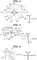
FIG. 4 is a bottom view of the outlet portion. -
FIG. 5 is a cross-sectional view in the V-V line ofFIG. 4 . -
FIG. 6 is a view for explaining the shape of a chamfered portion, and is a cross-sectional view in the VI-VI line ofFIG. 5 . -
FIG. 7 is a view for explaining the shape of a chamfered portion. -
FIG. 8 is a bottom view of the outlet portion, showing a modification example of the outlet. -
FIG. 9 is an explanation view showing the state when the sanitary tissue paper is taken out from the conventional storage container. - The following is a detailed description of an embodiment of the sanitary tissue paper storage container according to the present invention with reference to the drawings. Though the embodiments described below are provided with various limitations that are technically desirable for implementing the present invention, the scope of the present invention is not limited to the following embodiment and illustrated examples.
- In the following description, the front-rear direction, left-right direction and up-down direction, and the X-axis, Y-axis and Z-axis are defined as shown in
FIG. 1 . That is, in a sanitary tissuepaper storage container 100, the side on which the sanitary tissue paper is taken out and the side opposite thereto are respectively referred to as up and down, the front side in a plan view of the sanitary tissuepaper storage container 100 and the side opposite thereto are respectively referred to as front and rear, the right side when the front surface of the container is viewed from the front side is referred to as right, the left side when the front surface of the container is viewed from the front side is referred to as left, the axis along the front-rear direction is referred to as the X-axis, the axis along the left-right direction is referred to as the Y-axis, and the axis along the up-down direction is referred to as the Z-axis. - As shown in
FIG. 1 , the sanitary tissuepaper storage container 100 includes: acontainer body 1 inside which sanitary tissue paper (for example, roll paper such as a wet sheet or a wet tissue wound into a roll) is stored; alid 2 that is detachably attached to thecontainer body 1; and anoutlet portion 3 that is detachably attached to thelid 2, for example. - Since the
lid 2 is configured to be attachable and detachable with respect to thecontainer body 1, it is possible to store the sanitary tissue paper inside thecontainer body 1 and take out the sanitary tissue paper from inside, in a state in which thelid 2 is removed from thecontainer body 1. - The sanitary tissue paper is stored in the
container body 1 in a state in which the sanitary tissue paper is wound into a roll around an axis along the up-down direction. The sanitary tissue paper has perforations at regular intervals in a length direction, and the user uses a sheet of sanitary tissue paper which was cut off along the perforations. - The
container body 1 is a container for storing the sanitary tissue paper, which is formed in a bottomed cylindrical shape and has an opening in the upper surface. Amale screw portion 11 is provided along the circumferential direction on the outer circumferential surface of the upper end portion of the lateral surface, as shown inFIG. 2 . - The
container body 1 is formed of PE (polyethylene), PP (polypropylene), PET (polyethylene terephthalate), ABS resin, or the like, for example. - The
container body 1 is formed in a cylindrical shape that is a circle in a plan view with a diameter of 50 mm to 200 mm, 45 mm to 200 mm in the Z-axis direction (height), and has a thickness of each surface of 0.5 mm to 10 mm. - As shown in
FIGS. 1 and2 , thelid 2 is configured by a lidmain body 21 and asmall lid 22. - The lid
main body 21 is formed of PE (polyethylene), PP (polypropylene), PET (polyethylene terephthalate), ABS resin, or the like, for example. The lidmain body 21 is in a cylindrical shape in which the lower surface is open, and includes atop surface 21a, alateral surface 21b, arecessed portion 21c that is formed to be recessed downward on the inner circumferential side in a plan view of thetop surface 21a, ahole portion 21d, and a main-body-side wall 21e that is provided to rise in a cylindrical shape so as to surround thehole portion 21d inside the recessedportion 21c. - The lid
main body 21 is formed in a cylindrical shape that is a circle in a plan view with a diameter of 50 mm to 200 mm, 15 mm to 50 mm in the Z-axis direction (height), and has a thickness of each surface of 0.5 mm to 10 mm. - A
female screw portion 211 into which themale screw portion 11 of thecontainer body 1 screws is provided on the internal circumferential surface of the lower end of thelateral surface 21b. Thus, as shown inFIG. 2 , thecontainer body 1 and thelid 2 have an attachable and detachable connection structure via themale screw portion 11 and thefemale screw portion 211, which allows thelid 2 to be detached from thecontainer body 1. - The
recessed portion 21c is formed to have a nearly same shape in a plan view as thesmall lid 22 when thesmall lid 22 is closed, so that thesmall lid 22 can fit into therecessed portion 21c. Therecessed portion 21c is formed to have the front end larger than the front end of thesmall lid 22 in a plan view so as to leave a slight gap even in a state in which thesmall lid 22 is fitted into therecessed portion 21c. Thus, it is possible to get a finger caught on thesmall lid 22 by using the gap. - The
hole portion 21d is a hole formed in a circle in a plan view in the nearly center in a plan view of the lidmain body 21 and leading to the inside of the sanitary tissuepaper storage container 100. Thehole portion 21d is formed to be slightly smaller than theoutlet portion 3 in a plan view and theoutlet portion 3 is fixed to thehole portion 21d as mentioned later. - The main-body-
side wall 21e is formed to protrude upward in a cylindrical shape inside the recessedportion 21c, so as to surround thehole portion 21d. The main-body-side wall 21e is formed to have the outer diameter same as or slightly smaller than the internal diameter of a small-lid-side wall 22a formed in thesmall lid 22. - The
small lid 22 is formed of PE (polyethylene), PP (polypropylene), PET (polyethylene terephthalate), ABS resin, or the like, for example. Thesmall lid 22 has the end connected to the lidmain body 21, and includes the small-lid-side wall 22a protruding from the lower surface at the time of closing. Thesmall lid 22 is formed such that the shape in a plan view when thesmall lid 22 is closed nearly matches the shape of the recessedportion 21c and thesmall lid 22 can be fitted to the recessedportion 21c when thesmall lid 22 is closed. - The small-lid-
side wall 22a is formed in a cylindrical shape protruding downward when thesmall lid 22 is closed. The small-lid-side wall 22a is formed to have the internal diameter same as or slightly larger than the outer diameter of the main-body-side wall 21e. In addition, this small-lid-side wall 22a is configured to contact the upper surface of the recessedportion 21c when thesmall lid 22 is closed. Thus, when thesmall lid 22 is closed, the small-lid-side wall 22a can fit to the main-body-side wall 21e, and it is possible to maintain airtightness of the space surrounded by the small-lid-side wall 22a and the main-body-side wall 21e, and thus maintain airtightness of the space inside the sanitary tissuepaper storage container 100 that is connected to the space via thehole portion 21d. - In the present embodiment, the airtightness inside the sanitary tissue
paper storage container 100 is maintained by fitting the main-body-side wall 21e to the small-lid-side wall 22a. However, any configuration different from the above is possible as long as the configuration can maintain the airtightness inside the sanitary tissuepaper storage container 100. - In a case where the sanitary tissue paper to be stored is not soaked with chemical solution or the like and does not need to avoid drying, any configuration not especially including air tightness means may be used.
- As shown in
FIGS. 3 and4 , theoutlet portion 3 is an elastically deformable member that is formed in a nearly round pillar shape which is a circle in a plan view. Theoutlet portion 3 can be formed by injection molding, for example.FIG. 4 is a bottom view of theoutlet portion 3, showing the state ofoutlet portion 3 ofFIG. 3 seen from below. - To be specific, the
outlet portion 3 includes arecess 31 that has an internalbottom surface 3a formed in the center in a plan view, anarrow portion 32 that is formed on the lateral surface, anoutlet 33 that is formed in the nearly center in a plan view of the recess 31 (internalbottom surface 3a), and chamfered portions (first chamferedportions 341, second chamfered portions 342) that are formed by chamfering the peripheral edge of theoutlet 33 on thelower surface 3b. - The
outlet portion 3 has a circle shape that is slightly larger than thehole portion 21d between one tenth to one third inclusive the diameter of the lidmain body 21 in a plan view. - The thickness R1 (see
FIG. 5 ) in the Z-axis direction (dimension between the internalbottom surface 3a and thelower surface 3b) below thenarrow portion 32 in theoutlet portion 3 is between 1.0 mm and 5.0 mm, preferably between 1.5 mm and 3.0 mm. If the thickness in the Z-axis direction is excessively small, the sheet will not be cut and the sheets will come out continuously, and if the thickness in the Z-axis direction is excessively large, the sheet will be cut before the next sheet comes out. - On the upper surface of the
outlet portion 3, therecess 31 is formed to be recessed downward in a circle from the upper view, leaving the peripheral portion. The depth (depth in Z-axis direction) of thisrecess 31 is between 2 mm and 10 mm. - The
recess 31 is formed such that the internalbottom surface 3a is a flat face. - The
narrow portion 32 is formed in a groove shape recessed in a radial direction to have a depth between one twentieth and one tenth inclusive the diameter of theoutlet portion 3 in a plan view, surrounding the nearly central portion in the up-down direction of the lateral surface of theoutlet portion 3 along the circumferential direction. The dimension in the Z-axis direction of thenarrow portion 32 is between 0.5 mm and 3.0 mm. - Since the
outlet portion 3 is formed to be slightly larger than thehole portion 21d in a plan view as described above, by fitting the edge of thehole portion 21d into thenarrow portion 32, it is possible to fix theoutlet portion 3 to the lidmain body 21. - The
outlet 33 is a hole for taking out the sanitary tissue paper stored inside thecontainer body 1. - The sanitary tissue paper is inserted through the
outlet 33 from thelower surface 3b side, and theoutlet 33 holds the sanitary tissue paper with its tip-side end protruding from the upper surface of the outlet portion 3 (internalbottom surface 3a of the recess 31). - When the tip end of the sanitary tissue paper is in a state of protruding from the upper surface of the
outlet portion 3, the protruding amount is 10 mm to 30 mm, preferably 13 mm to 20 mm. Such a protruding amount facilitates plucking with a general user's finger, and the taking-out operation can be performed easily. - The
outlet 33 typically has asmall hole 33a, which is nearly circular in a plan view, andmultiple slits 33b formed radially around thesmall hole 33a. The term "nearly circular" here includes not only a perfect circle, but also an oval or a distorted circle. - In the embodiment, four
slits 33b are provided around thesmall hole 33a, as shown inFIG. 3 andFIG. 4 , for example. Theslits 33b are provided at 90 degrees intervals around thesmall hole 33a. - The diameter of the
small hole 33a is between 1.0 mm and 5.0 mm, preferably between 2.0 mm and 4.0 mm. If the diameter of thesmall hole 33a is excessively large, the next sheet will not be retained and will fall into the hole, and if the diameter of thesmall hole 33a is excessively small, more force will be required for taking out the sheet. - The length R2 of the
slit 33b (seeFIG. 5 ) is between 2 mm and 10 mm. - In this way, if the
outlet 33 is composed of thesmall hole 33a and themultiple slits 33b, it is possible to achieve both of reliability of holding the sanitary tissue paper in theoutlet 33 and easiness of pulling out the sanitary tissue paper that is held in theoutlet 33. - In
FIG. 3 andFIG. 4 , a case in which fourslits 33b are formed is illustrated and described, but the shape of theoutlet 33 is not limited to this, and any number ofslits 33b may be formed as long as the above functions can be fulfilled. In other words, theoutlet 33 can be a combination of asmall hole 33a of a perfect circle or oval and any number ofslits 33b. - As shown in
FIGS. 4 and 5 , each of the chamfered portions (first chamferedportions 341, second chamfered portions 342) is a region obtained by chamfering the corner that is formed by thelower surface 3b of theoutlet portion 3 and thehole wall 33h of theoutlet 33. - To be specific, each of the chamfered portions (first chamfered
portions 341, second chamfered portions 342) is a flat chamfered portion obtained by chamfering the edge of thehole wall 33h of theoutlet 33 on thelower surface 3b of theoutlet portion 3 with an inclined flat face. By forming the chamfered portions, theoutlet 33 has such a shape that the opening area on the lower end side is larger than the opening area on the upper end side. - In the embodiment, there are provided the first
chamfered portions 341 each of which is formed by chamfering the corner formed by thehole wall 33h of theslit 33b and thelower surface 3b of theoutlet portion 3, and the secondchamfered portions 342 each of which is formed by chamfering the corner formed by thehole wall 33h of thesmall hole 33a and thelower surface 3b of theoutlet portion 3. - As shown in
FIG. 6 , the size of each chamfered portion (first chamferedportion 341, second chamfered portion 342) is preferably set such that the length L1 in the width direction (direction along the XY plane) of theoutlet 33 from thehole wall 33h of theoutlet 33 is within the range of 0.1 mm to 0.5 mm and the length L2 in the height direction (direction along the Z-axis direction) from the lower end of theoutlet 33 is within the range of 0.1 mm to 0.5 mm. - By providing such chamfered portions (first chamfered
portions 341, second chamfered portions 342) at the lower edge of theoutlet 33, it is possible to suitably pull out the sanitary tissue paper held by theoutlet 33. - In the embodiment, the case of forming each of the chamfered portions (first chamfered
portions 341, second chamfered portions 342) by chamfering to be a flat face has been described by illustration. However, as shown inFIG. 7 , the chamfered portion may be a curved chamfered portion obtained by chamfering the corner, which is formed by thelower surface 3b of theoutlet portion 3 and thehole wall 33h of theoutlet 33, to be a convex curved face. - As shown in
FIG. 8 , only theslit 33b portions in theoutlet 33 may have first chamferedportions 341, without forming chamfered portions at thesmall hole 33a portion in theoutlet 33. - In a case where the force necessary to pull out the sanitary tissue paper in the
above outlet portion 3 is measured 5 times by using a digital force gauge (manufactured by IMADA: model number DS2-200N) and the average value is defined as a resistance value, the value of such a resistance value is preferably within the range of 5 to 12 N, and more preferably 7 to 9 N. - When sanitary tissue paper wound in a single roll (for example, continuous 80 sheets having 79 lines of perforations) is pulled out, the allowable range of the number of times (number of continuations) that a sheet is not cut along the perforations and the subsequent sheet of sanitary tissue paper comes out following the sheet is 10 times or less, and preferably 5 times or less.
- In the above-mentioned sanitary tissue
paper storage container 100, by applying a resistance to the pulled-out sanitary tissue paper with theoutlet 33 that has thesmall hole 33a andmultiple slits 33b, the sheet of the sanitary tissue paper to be used is cut off along the perforations, and the subsequent sheet of the sanitary tissue paper can be held in a state in which the proper amount of end is protruding from theoutlet 33. - In particular, by having the chamfered portions (first chamfered
portions 341, second chamfered portions 342), the resistance when the sanitary tissue paper passes through theoutlet 33 is reduced compared to the case of not having the chamfered portions. Thus, it is possible to sufficiently secure the protruding amount of the subsequent sheet of sanitary tissue paper protruding from theoutlet 33, and the force necessary for pulling out is also reduced, thus facilitating the taking-out operation. - According to the embodiment, in a sanitary tissue
paper storage container 100 including: acontainer body 1 inside which sanitary tissue paper is stored; and alid 2 that is detachably attached to thecontainer body 1 and that has anoutlet portion 3 to take out the sanitary tissue paper stored in thecontainer body 1, theoutlet portion 3 includes anoutlet 33 through which the sanitary tissue paper is inserted and which holds an end on a tip side of the sanitary tissue paper protruding from an upper surface (internalbottom surface 3a of the recess 31) of theoutlet portion 3, theoutlet 33 includes asmall hole 33a that is nearly circular andmultiple slits 33b that are formed radially around thesmall hole 33a. First chamferedportions 341 are provided to theslits 33b, each of the firstchamfered portions 341 being a corner that is chamfered, and the corner being formed by ahole wall 33h of theslit 33b and alower surface 3b of theoutlet portion 3. In addition, secondchamfered portions 342 may be provided to thesmall hole 33a of theoutlet 33, each of the secondchamfered portions 342 being a corner that is chamfered, and the corner being formed by ahole wall 33h of thesmall hole 33a and thelower surface 3b of theoutlet portion 3. - Since the sanitary tissue
paper storage container 100 in the embodiment has such a configuration, it is possible to achieve both of reliability of holding the sanitary tissue paper in theoutlet 33 and easiness of operation of taking out the sanitary tissue paper. - According to the embodiment, each of the chamfered portions (first chamfered
portions 341 and second chamfered portions 342) is a flat chamfered portion in which thehole wall 33h of theoutlet 33 is chamfered to be a flat face, or a curved chamfered portion in which thehole wall 33h of theoutlet 33 is chamfered to be a convex curved face. - By selecting either a flat chamfered portion or a curved chamfered portion as the chamfered portion to be formed on the
outlet 33, theoutlet 33 can be made suitable for taking out the sanitary tissue paper to be used. For example, by selecting the curved chamfered portions as the chamfered portions (first chamferedportions 341 and second chamfered portions 342), theoutlet 33 can be made to make it easier to pull out the sanitary tissue paper. - According to the present embodiment, in the
outlet 33 provided with the chamfered portions (first chamferedportions 341 and second chamfered portions 342) on its lower edge, an opening area on a lower end side is larger than an opening area on an upper end side. - Thus, it is possible to facilitate the operation of taking out the sanitary tissue paper.
- According to the present embodiment, the
lid 2 includes ahole portion 21d in an upper surface, and theoutlet portion 3 includes anarrow portion 32 that is provided on a lateral surface, and an edge of thehole portion 21d is fitted to thenarrow portion 32 to attach theoutlet portion 3 to thelid 2. - Thus, it is possible to suitably attach the
outlet portion 3 to thelid 2. In addition, it is also possible to replace theoutlet portion 3. - The sanitary tissue paper stored in the sanitary tissue
paper storage container 100 is not necessarily limited to the sanitary tissue paper wound in a roll. For example, there can be used so called pop-up type sheets that are laminated in a state of being folded in an alternate manner and formed such that, when one sheet of sanitary tissue paper is taken out, the next sheet of sanitary tissue paper is also pulled out to theoutlet 33. - The shape of the sanitary tissue
paper storage container 100 may not necessarily be a cylindrical shape. - Next, the results of evaluating the easiness of taking out the sanitary tissue paper for Examples of the present invention and Comparative Examples are described. Hereinafter, though the present invention is described specifically by the Examples, the present invention is not limited to them.
- As a sanitary tissue
paper storage container 100, there was prepared a container that has the shape shown inFIG. 1 and is made of polyethylene, the container having acontainer body 1 and alid 2 that is detachably attached to thecontainer body 1. - The
outlet portion 3 of each of the following Examples 1 to 3 and Comparative Examples 1 to 2 is attached to this sanitary tissuepaper storage container 100. - The
outlet portion 3 of each of the Examples 1 to 3 has a shape shown inFIGS. 3 to 6 , and made of elastomer. - The thickness R1 in the Z-axis direction of the
outlet portion 3 is 3.0 mm. - The
outlet 33 having asmall hole 33a with the diameter of 2.8 mm (Example 1, Example 2), 3.8 mm (Example 3) and havingslits 33b each with the length R2 of 5.1 mm (Example 1, Example 2), 4.6 mm (Example 3) was prepared. - This length of
slit 33b was measured by using the ABS DIGIMATIC CALIPER (manufactured by Mitutoyo: model number CD-20APX). - The lengths L1 and L2 of each of the chamfered portions (first chamfered
portions 341 and second chamfered portions 342) were L1=L2=0.1 mm (Example 1, Example 3) and L1=L2=1.0 mm (Example 2). - L1 is the length in the direction along the XY plane, and L2 is the length in the direction along the Z-axis.
- The
outlet portion 3 in the Comparative Example 1 was same as that of the Example 1, except that the chamfered portions were not provided (that is, L1=L2=0mm). - The
outlet portion 3 in the Comparative Example 2 was same as that of the Example 3, except that the chamfered portions are not provided (that is, L1=L2=0mm). - As the sanitary tissue paper, a wet sheet that is wound in a roll and has lines of perforations at regular intervals in the longitudinal direction was used. To be specific, the number of lines of perforations was 79 and the wet sheet having the 80 continuous sheets was used.
- A general nonwoven fabric (e.g., a nonwoven fabric made of rayon) was used for the wet sheet here.
- By using the samples of the Examples 1 to 3 and the Comparative Examples 1 to 2, (1) Protruding amount of subsequent sheet of sanitary tissue paper, (2) Resistance value at the time of taking out and (3) Number of continuations, were measured as follows and the results were shown in Table I.
- (1) Protruding Amount of Subsequent Sheet of Sanitary Tissue Paper
The above one wet sheet wound in a roll was pulled out by using the samples of the above Examples 1 to 3 and Comparative Example 1, and the average value of measured values of the protruding amount of subsequent sheet in the wet sheet was calculated as a protruding amount of sanitary tissue paper.
The protruding amount of wet sheet was measured by using the ABS DIGIMATIC CALIPER (manufactured by Mitutoyo: model number CD-20APX). - (2) Resistance Value when Sanitary Tissue Paper was Taken Out
The above wet sheet wound in a roll was pulled out by using the samples of the above Examples 1 to 3 and Comparative Example 1, and the force necessary for the pulling out was measured by using the digital force gauge (manufactured by IMADA: model number DS2-200N). The measurement was performed 5 times for each sample, and the average value thereof was determined as the resistance value. - (3) Number of Continuations
The above one wet sheet wound in a roll was pulled out by using the samples of the above Examples 1 to 3 and Comparative Example 1, and the number of times that a sheet is not cut along the perforations and the subsequent sheet of sanitary tissue paper comes out following the sheet was counted as the number of continuations. -
TABLE I Example 1 Example 2 Example 3 Comparative Example 1 Comparative Example 2 Diameter of Small Hole [mm] 2.8 2.8 3.8 2.8 3.8 Length of Slit (R2) [mm] 5.1 5.1 4.6 5.1 4.6 Chamfered Amount (L1=L2) [mm] 0.1 1.0 0.1 None (0.0) None (0.0) Evaluation Protruding Amount [mm] 11.5 22.5 15.2 10.2 12.4 Number of Continuations [times] 0.7 6.0 1.0 0.5 0.0 Resistance Value [N] 10.3 5.9 7.8 13.1 8.5 - In the results of Table 1, comparison between the Example 1 and the Comparative Example 1 show that the Example 1 having the chamfered portions on the
outlet 33 has a longer protruding amount and a lower resistance value, and thus facilitates picking of the sanitary tissue paper and enables to suitably take out the sanitary tissue paper. - In addition, comparison between the Example 3 and the Comparative Example 2 show that the Example 3 having the chamfered portions on the
outlet 33 has a longer protruding amount and a lower resistance value, and thus facilitates picking of the sanitary tissue paper and enables to suitably take out the sanitary tissue paper. - In particular, the Example 3 has the protrusion amount of 15.2 mm, the number of continuations of 1 time, and the resistance value of 7.8 N, which are more preferable numerical values in the respective evaluations. This means that the sanitary tissue paper can be picked more easily and taken out suitably.
- As shown above, by having chamfered portions (first chamfered
portions 341, second chamfered portions 342) on the lower edge of theoutlet 33 having thesmall hole 33a andmultiple slits 33b (Examples 1 to 3), it is possible to achieve both of reliability of holding the sanitary tissue paper and easiness of operation of taking out the sanitary tissue paper. - The application of the present invention is not limited to the above-mentioned embodiment, and modifications can be appropriately made within the scope of the present invention.
- Since the present invention is configured as described above, the present invention can be used as a sanitary tissue paper storage container that achieves both of reliability of holding the sanitary tissue paper in the outlet and easiness of operation of taking out the sanitary tissue paper.
-
- 1
- container body
- 11
- male screw portion
- 2
- lid
- 21
- lid main body
- 21a
- top surface
- 21b
- lateral surface
- 21c
- recessed portion
- 21d
- hole portion
- 21e
- main-body-side wall
- 211
- female screw portion
- 22
- small lid
- 22a
- small-lid-side wall
- 3
- outlet portion
- 3a
- internal bottom surface
- 3b
- lower surface
- 31
- recess
- 32
- narrow portion
- 33
- outlet
- 33a
- small hole
- 33b
- slit
- 33h
- hole wall
- 341
- first chamfered portion
- 342
- second chamfered portion
- 100
- sanitary tissue paper storage container
Claims (5)
- A sanitary tissue paper storage container comprising:a container body inside which sanitary tissue paper is stored; anda lid that is detachably attached to the container body and that has an outlet portion to take out the sanitary tissue paper stored in the container body, whereinthe outlet portion includes an outlet through which the sanitary tissue paper is inserted and which holds an end of the sanitary tissue paper protruding from an upper surface of the outlet portion,the outlet includes a small hole that is nearly circular and multiple slits that are formed radially around the small hole, anda first chamfered portion is provided to a slit among the slits, the first chamfered portion being a corner that is chamfered, and the corner being formed by a hole wall of the slit and a lower surface of the outlet portion.
- The sanitary tissue paper storage container according to claim 1, wherein a second chamfered portion is provided to the small hole, the second chamfered portion being a corner that is chamfered, and the corner being formed by a hole wall of the small hole and the lower surface of the outlet portion.
- The sanitary tissue paper storage container according to claim 1 or 2, wherein the first chamfered portion is a flat chamfered portion in which the hole wall is chamfered to be a flat face, or the first chamfered portion is a curved chamfered portion in which the hole wall is chamfered to be a convex curved face.
- The sanitary tissue paper storage container according to claim 2 or 3, wherein the second chamfered portion is a flat chamfered portion in which the hole wall is chamfered to be a flat face, or the second chamfered portion is a curved chamfered portion in which the hole wall is chamfered to be a convex curved face.
- The sanitary tissue paper storage container according to any one of claims 1 to 4, whereinthe lid includes a hole portion in an upper surface, andthe outlet portion includes a narrow portion that is provided on a lateral surface, and an edge of the hole portion is fitted to the narrow portion to attach the outlet portion to the lid.
Applications Claiming Priority (2)
| Application Number | Priority Date | Filing Date | Title |
|---|---|---|---|
| JP2019154195A JP2021031138A (en) | 2019-08-27 | 2019-08-27 | Sanitary tissue paper storage container |
| PCT/JP2020/030605 WO2021039382A1 (en) | 2019-08-27 | 2020-08-11 | Sanitary tissue paper storage container |
Publications (2)
| Publication Number | Publication Date |
|---|---|
| EP3998220A1 true EP3998220A1 (en) | 2022-05-18 |
| EP3998220A4 EP3998220A4 (en) | 2022-08-10 |
Family
ID=74675179
Family Applications (1)
| Application Number | Title | Priority Date | Filing Date |
|---|---|---|---|
| EP20856557.2A Pending EP3998220A4 (en) | 2019-08-27 | 2020-08-11 | STORAGE CONTAINER FOR SANITARY PAPER |
Country Status (6)
| Country | Link |
|---|---|
| US (1) | US20220267082A1 (en) |
| EP (1) | EP3998220A4 (en) |
| JP (1) | JP2021031138A (en) |
| KR (1) | KR20220050095A (en) |
| CN (1) | CN114025650A (en) |
| WO (1) | WO2021039382A1 (en) |
Families Citing this family (1)
| Publication number | Priority date | Publication date | Assignee | Title |
|---|---|---|---|---|
| TWI755285B (en) * | 2021-02-23 | 2022-02-11 | 東咨實業有限公司 | wet wipes airtight container |
Family Cites Families (42)
| Publication number | Priority date | Publication date | Assignee | Title |
|---|---|---|---|---|
| US4017002A (en) * | 1969-09-08 | 1977-04-12 | Sterling Drug Inc. | Dispensing moist treated towels or tissues |
| US4337876A (en) * | 1979-08-23 | 1982-07-06 | Sterling Drug Inc. | Apparatus for dispensing articles |
| JPS5850521B2 (en) | 1979-10-09 | 1983-11-11 | 日東電工株式会社 | Selective permeable membrane made of polyquinazolone polymer |
| US4534491A (en) * | 1982-07-06 | 1985-08-13 | Scott Paper Company | Wet tissue dispensing port |
| JPH0311889U (en) | 1989-06-21 | 1991-02-06 | ||
| US5219421A (en) * | 1992-06-16 | 1993-06-15 | Reid Dominion Packaging Limited | Paperboard tissue box with paperboard dispenser |
| US5467893A (en) * | 1994-04-13 | 1995-11-21 | Sanford Corporation | Storage and dispensing canister for moist cloth |
| JP3318166B2 (en) * | 1995-08-04 | 2002-08-26 | 中村 憲司 | Wet tissue package |
| US5718353A (en) * | 1996-05-08 | 1998-02-17 | Gojo Industries, Inc. | Towelette dispensing closure assembly |
| JPH10101092A (en) * | 1996-10-02 | 1998-04-21 | Toppan Printing Co Ltd | Cap with small lid |
| US5908138A (en) * | 1997-12-18 | 1999-06-01 | Eftichios Van Vlahakis | Dispensing lid |
| JP3981753B2 (en) * | 1998-03-18 | 2007-09-26 | 清志 川崎 | Extraction structure of wet tissue container |
| EP0953516A1 (en) * | 1998-04-28 | 1999-11-03 | The Procter & Gamble Company | A tissue box |
| US6056235A (en) * | 1998-05-28 | 2000-05-02 | Brozinsky; Steven | Refillable dispenser for replacing standard roll of toilet tissue with roll of pre-moistened wipes |
| US6279775B1 (en) * | 1999-02-08 | 2001-08-28 | Remington Industries, Inc. | Tissue dispenser for a vehicle cup holder |
| IL129856A (en) * | 1999-05-10 | 2002-02-10 | Albaad Massuot Yitzhak Ltd | Dispensing cover |
| US6318590B1 (en) * | 1999-05-11 | 2001-11-20 | Mcmurray-Stivers Lisa | Travel tissue holder |
| US6364101B1 (en) * | 2000-10-19 | 2002-04-02 | S. C. Johnson & Son, Inc. | Easily opened wipes canister |
| US6550633B2 (en) * | 2001-05-31 | 2003-04-22 | Kimberly-Clark Worldwide, Inc. | Process for joining wet wipes together and product made thereby |
| US6840401B2 (en) * | 2002-12-19 | 2005-01-11 | Kimberly-Clark Worldwide, Inc. | Multiple layer baffle structure for dispenser for wipes |
| US7354598B2 (en) * | 2002-12-20 | 2008-04-08 | Kimberly-Clark Worldwide, Inc. | Packaging two different substrates |
| US6945424B1 (en) * | 2003-01-29 | 2005-09-20 | Intercycle Llc | Newspaper recycling container |
| US6889867B1 (en) * | 2003-10-28 | 2005-05-10 | Randall J. Smith | Lidded container |
| US20050205593A1 (en) * | 2004-03-19 | 2005-09-22 | Allen Young | Wipe dispensing system |
| US20060180596A1 (en) * | 2004-03-19 | 2006-08-17 | Allen Young | Wipe dispensing system |
| US20050269344A1 (en) * | 2004-06-07 | 2005-12-08 | Madsen Gary F | Dispensing cover and substrate dispenser |
| US7597213B2 (en) * | 2004-12-22 | 2009-10-06 | Kimberly-Clark Worldwide, Inc. | Container caps and containers |
| US20060191933A1 (en) * | 2005-02-25 | 2006-08-31 | Seaquist Closures Foreign, Inc. | Closure system with improved sealing of lid |
| US7303069B2 (en) * | 2005-05-25 | 2007-12-04 | Illinois Tool Works, Inc. | Pre-moistened fiber optic component cleaning tool with integrated platen |
| FR2901248B1 (en) * | 2006-05-19 | 2010-09-17 | Airsec | DEVICE FOR DISTRIBUTOR / LIMITER OF UNITARY PRODUCTS FLOW RATE, INTEGRATED WITH A CONTAINER AND IN-SITU TREATMENT OF ITS INTERNAL ATMOSPHERE |
| JP5236997B2 (en) * | 2008-05-29 | 2013-07-17 | 大王製紙株式会社 | Household thin paper storage container |
| US20100133287A1 (en) * | 2008-12-02 | 2010-06-03 | Paul Francis Tramontina | Ergonomic Wiper Dispensing System |
| JP2012192962A (en) | 2011-03-17 | 2012-10-11 | Kikuo Yamada | Wet tissue storage container |
| JP5850521B2 (en) | 2011-08-31 | 2016-02-03 | 日本製紙クレシア株式会社 | Wet tissue storage container |
| US9101250B2 (en) * | 2012-05-21 | 2015-08-11 | Gojo Industries, Inc. | Wipes dispenser nozzle |
| US9694554B2 (en) * | 2013-01-08 | 2017-07-04 | Danco Packaging Supply Company | Apparatus, system and method for crumpling paper |
| US9974419B2 (en) * | 2014-04-23 | 2018-05-22 | The Clorox Company | Disinfecting wipes dispenser |
| JP6198877B1 (en) * | 2016-03-30 | 2017-09-20 | 大王製紙株式会社 | Sanitary tissue paper storage container |
| JP6280586B2 (en) * | 2016-03-30 | 2018-02-14 | 大王製紙株式会社 | Sanitary tissue paper storage container |
| US10722082B2 (en) * | 2016-08-12 | 2020-07-28 | Edgewell Personal Care Brands, Llc | Diaphragm for a container assembly |
| JP7299039B2 (en) * | 2019-02-28 | 2023-06-27 | 大王製紙株式会社 | sanitary tissue paper container |
| JP2021054494A (en) * | 2019-09-30 | 2021-04-08 | 大王製紙株式会社 | Sanitary tissue paper storage container, takeout member of sanitary tissue paper storage container and manufacturing method for takeout member of sanitary tissue paper storage container |
-
2019
- 2019-08-27 JP JP2019154195A patent/JP2021031138A/en active Pending
-
2020
- 2020-08-11 US US17/629,004 patent/US20220267082A1/en not_active Abandoned
- 2020-08-11 KR KR1020217043046A patent/KR20220050095A/en not_active Ceased
- 2020-08-11 EP EP20856557.2A patent/EP3998220A4/en active Pending
- 2020-08-11 WO PCT/JP2020/030605 patent/WO2021039382A1/en not_active Ceased
- 2020-08-11 CN CN202080046776.0A patent/CN114025650A/en active Pending
Also Published As
| Publication number | Publication date |
|---|---|
| CN114025650A (en) | 2022-02-08 |
| JP2021031138A (en) | 2021-03-01 |
| BR112022002678A2 (en) | 2022-05-03 |
| WO2021039382A1 (en) | 2021-03-04 |
| EP3998220A4 (en) | 2022-08-10 |
| US20220267082A1 (en) | 2022-08-25 |
| KR20220050095A (en) | 2022-04-22 |
Similar Documents
| Publication | Publication Date | Title |
|---|---|---|
| EP3901059B1 (en) | Storage container for sanitary tissue paper | |
| EP3438018B1 (en) | Container for accommodating hygienic thin paper | |
| JP6198877B1 (en) | Sanitary tissue paper storage container | |
| US20220267082A1 (en) | Sanitary tissue paper storage container | |
| EP3521197B1 (en) | Wet sheet storage container | |
| WO2021065359A1 (en) | Hygiene thin paper accommodation container, extraction member of hygiene thin paper accommodation container, and method for manufacturing extraction member of hygiene thin paper accommodation container | |
| RU2790735C2 (en) | Thin hygienic paper storage container | |
| JP6564480B1 (en) | Sheet-like material storage container and sheet-like material dispensing chip | |
| JP2018140810A (en) | Sanitary tissue paper storage container | |
| JP7365943B2 (en) | Sanitary tissue paper storage container | |
| BR112022002678B1 (en) | TOILET TISSUE STORAGE CONTAINER | |
| JP7818887B2 (en) | Sanitary tissue paper storage container | |
| JP7826153B2 (en) | Sanitary tissue paper storage container | |
| JP2022085211A (en) | Sanitary tissue paper storage container | |
| US11382728B2 (en) | Floss dispenser | |
| JP2024157580A (en) | Sanitary tissue storage products |
Legal Events
| Date | Code | Title | Description |
|---|---|---|---|
| STAA | Information on the status of an ep patent application or granted ep patent |
Free format text: STATUS: THE INTERNATIONAL PUBLICATION HAS BEEN MADE |
|
| PUAI | Public reference made under article 153(3) epc to a published international application that has entered the european phase |
Free format text: ORIGINAL CODE: 0009012 |
|
| STAA | Information on the status of an ep patent application or granted ep patent |
Free format text: STATUS: REQUEST FOR EXAMINATION WAS MADE |
|
| 17P | Request for examination filed |
Effective date: 20220210 |
|
| AK | Designated contracting states |
Kind code of ref document: A1 Designated state(s): AL AT BE BG CH CY CZ DE DK EE ES FI FR GB GR HR HU IE IS IT LI LT LU LV MC MK MT NL NO PL PT RO RS SE SI SK SM TR |
|
| A4 | Supplementary search report drawn up and despatched |
Effective date: 20220711 |
|
| RIC1 | Information provided on ipc code assigned before grant |
Ipc: B65D 83/08 20060101AFI20220705BHEP Ipc: A47K 10/42 20060101ALI20220705BHEP Ipc: A47K 10/38 20060101ALI20220705BHEP Ipc: A47K 10/00 20060101ALI20220705BHEP |
|
| DAV | Request for validation of the european patent (deleted) | ||
| DAX | Request for extension of the european patent (deleted) | ||
| RAP3 | Party data changed (applicant data changed or rights of an application transferred) |
Owner name: DAIO PAPER CORPORATION |
|
| STAA | Information on the status of an ep patent application or granted ep patent |
Free format text: STATUS: EXAMINATION IS IN PROGRESS |
|
| 17Q | First examination report despatched |
Effective date: 20241212 |