EP3998100A1 - Endovascular cerebrospinal fluid shunt system - Google Patents
Endovascular cerebrospinal fluid shunt system Download PDFInfo
- Publication number
- EP3998100A1 EP3998100A1 EP21212943.1A EP21212943A EP3998100A1 EP 3998100 A1 EP3998100 A1 EP 3998100A1 EP 21212943 A EP21212943 A EP 21212943A EP 3998100 A1 EP3998100 A1 EP 3998100A1
- Authority
- EP
- European Patent Office
- Prior art keywords
- shunt
- sinus
- cerebrospinal
- ecsfs
- fluid
- Prior art date
- Legal status (The legal status is an assumption and is not a legal conclusion. Google has not performed a legal analysis and makes no representation as to the accuracy of the status listed.)
- Pending
Links
Images


Classifications
-
- A—HUMAN NECESSITIES
- A61—MEDICAL OR VETERINARY SCIENCE; HYGIENE
- A61M—DEVICES FOR INTRODUCING MEDIA INTO, OR ONTO, THE BODY; DEVICES FOR TRANSDUCING BODY MEDIA OR FOR TAKING MEDIA FROM THE BODY; DEVICES FOR PRODUCING OR ENDING SLEEP OR STUPOR
- A61M27/00—Drainage appliance for wounds or the like, i.e. wound drains, implanted drains
- A61M27/002—Implant devices for drainage of body fluids from one part of the body to another
- A61M27/006—Cerebrospinal drainage; Accessories therefor, e.g. valves
-
- A—HUMAN NECESSITIES
- A61—MEDICAL OR VETERINARY SCIENCE; HYGIENE
- A61B—DIAGNOSIS; SURGERY; IDENTIFICATION
- A61B90/00—Instruments, implements or accessories specially adapted for surgery or diagnosis and not covered by any of the groups A61B1/00 - A61B50/00, e.g. for luxation treatment or for protecting wound edges
- A61B90/39—Markers, e.g. radio-opaque or breast lesions markers
-
- A—HUMAN NECESSITIES
- A61—MEDICAL OR VETERINARY SCIENCE; HYGIENE
- A61B—DIAGNOSIS; SURGERY; IDENTIFICATION
- A61B17/00—Surgical instruments, devices or methods, e.g. tourniquets
- A61B17/12—Surgical instruments, devices or methods, e.g. tourniquets for ligaturing or otherwise compressing tubular parts of the body, e.g. blood vessels, umbilical cord
- A61B17/12022—Occluding by internal devices, e.g. balloons or releasable wires
- A61B17/12131—Occluding by internal devices, e.g. balloons or releasable wires characterised by the type of occluding device
- A61B17/12168—Occluding by internal devices, e.g. balloons or releasable wires characterised by the type of occluding device having a mesh structure
- A61B17/12172—Occluding by internal devices, e.g. balloons or releasable wires characterised by the type of occluding device having a mesh structure having a pre-set deployed three-dimensional shape
-
- A—HUMAN NECESSITIES
- A61—MEDICAL OR VETERINARY SCIENCE; HYGIENE
- A61B—DIAGNOSIS; SURGERY; IDENTIFICATION
- A61B90/00—Instruments, implements or accessories specially adapted for surgery or diagnosis and not covered by any of the groups A61B1/00 - A61B50/00, e.g. for luxation treatment or for protecting wound edges
- A61B90/39—Markers, e.g. radio-opaque or breast lesions markers
- A61B2090/3966—Radiopaque markers visible in an X-ray image
-
- A—HUMAN NECESSITIES
- A61—MEDICAL OR VETERINARY SCIENCE; HYGIENE
- A61F—FILTERS IMPLANTABLE INTO BLOOD VESSELS; PROSTHESES; DEVICES PROVIDING PATENCY TO, OR PREVENTING COLLAPSING OF, TUBULAR STRUCTURES OF THE BODY, e.g. STENTS; ORTHOPAEDIC, NURSING OR CONTRACEPTIVE DEVICES; FOMENTATION; TREATMENT OR PROTECTION OF EYES OR EARS; BANDAGES, DRESSINGS OR ABSORBENT PADS; FIRST-AID KITS
- A61F2/00—Filters implantable into blood vessels; Prostheses, i.e. artificial substitutes or replacements for parts of the body; Appliances for connecting them with the body; Devices providing patency to, or preventing collapsing of, tubular structures of the body, e.g. stents
- A61F2/82—Devices providing patency to, or preventing collapsing of, tubular structures of the body, e.g. stents
- A61F2/86—Stents in a form characterised by the wire-like elements; Stents in the form characterised by a net-like or mesh-like structure
- A61F2/88—Stents in a form characterised by the wire-like elements; Stents in the form characterised by a net-like or mesh-like structure the wire-like elements formed as helical or spiral coils
-
- A—HUMAN NECESSITIES
- A61—MEDICAL OR VETERINARY SCIENCE; HYGIENE
- A61F—FILTERS IMPLANTABLE INTO BLOOD VESSELS; PROSTHESES; DEVICES PROVIDING PATENCY TO, OR PREVENTING COLLAPSING OF, TUBULAR STRUCTURES OF THE BODY, e.g. STENTS; ORTHOPAEDIC, NURSING OR CONTRACEPTIVE DEVICES; FOMENTATION; TREATMENT OR PROTECTION OF EYES OR EARS; BANDAGES, DRESSINGS OR ABSORBENT PADS; FIRST-AID KITS
- A61F2/00—Filters implantable into blood vessels; Prostheses, i.e. artificial substitutes or replacements for parts of the body; Appliances for connecting them with the body; Devices providing patency to, or preventing collapsing of, tubular structures of the body, e.g. stents
- A61F2/82—Devices providing patency to, or preventing collapsing of, tubular structures of the body, e.g. stents
- A61F2/86—Stents in a form characterised by the wire-like elements; Stents in the form characterised by a net-like or mesh-like structure
- A61F2/90—Stents in a form characterised by the wire-like elements; Stents in the form characterised by a net-like or mesh-like structure characterised by a net-like or mesh-like structure
- A61F2/91—Stents in a form characterised by the wire-like elements; Stents in the form characterised by a net-like or mesh-like structure characterised by a net-like or mesh-like structure made from perforated sheet material or tubes, e.g. perforated by laser cuts or etched holes
-
- A—HUMAN NECESSITIES
- A61—MEDICAL OR VETERINARY SCIENCE; HYGIENE
- A61M—DEVICES FOR INTRODUCING MEDIA INTO, OR ONTO, THE BODY; DEVICES FOR TRANSDUCING BODY MEDIA OR FOR TAKING MEDIA FROM THE BODY; DEVICES FOR PRODUCING OR ENDING SLEEP OR STUPOR
- A61M2210/00—Anatomical parts of the body
- A61M2210/06—Head
- A61M2210/0693—Brain, cerebrum
-
- A—HUMAN NECESSITIES
- A61—MEDICAL OR VETERINARY SCIENCE; HYGIENE
- A61M—DEVICES FOR INTRODUCING MEDIA INTO, OR ONTO, THE BODY; DEVICES FOR TRANSDUCING BODY MEDIA OR FOR TAKING MEDIA FROM THE BODY; DEVICES FOR PRODUCING OR ENDING SLEEP OR STUPOR
- A61M2210/00—Anatomical parts of the body
- A61M2210/12—Blood circulatory system
-
- A—HUMAN NECESSITIES
- A61—MEDICAL OR VETERINARY SCIENCE; HYGIENE
- A61M—DEVICES FOR INTRODUCING MEDIA INTO, OR ONTO, THE BODY; DEVICES FOR TRANSDUCING BODY MEDIA OR FOR TAKING MEDIA FROM THE BODY; DEVICES FOR PRODUCING OR ENDING SLEEP OR STUPOR
- A61M25/00—Catheters; Hollow probes
- A61M25/01—Introducing, guiding, advancing, emplacing or holding catheters
- A61M25/02—Holding devices, e.g. on the body
- A61M25/04—Holding devices, e.g. on the body in the body, e.g. expansible
-
- A—HUMAN NECESSITIES
- A61—MEDICAL OR VETERINARY SCIENCE; HYGIENE
- A61M—DEVICES FOR INTRODUCING MEDIA INTO, OR ONTO, THE BODY; DEVICES FOR TRANSDUCING BODY MEDIA OR FOR TAKING MEDIA FROM THE BODY; DEVICES FOR PRODUCING OR ENDING SLEEP OR STUPOR
- A61M25/00—Catheters; Hollow probes
- A61M25/10—Balloon catheters
- A61M25/1011—Multiple balloon catheters
Definitions
- the present application relates to shunts capable of draining cerebrospinal fluid to the venous system.
- CSF cerebrospinal fluid
- the known shunts are limited to areas of placement due to fluid flow control; however, fluid flow still poses difficulties due to the complexity of the devices and the placement areas.
- the shunts/catheters are placed through the skull of the patient. This placement requires an open surgical procedure performed under general anesthesia.
- the shunts/catheters also require pressure control to facilitate CSF flow.
- the known shunts and methods of placements do not work in conjunction with a body's natural disease control processes.
- the present disclosure relates to endovascular CSF shunts that drain CSF from the subarachnoid space around the cerebellum into a dural venous sinus.
- the phrase "dural venous sinus” and other references to the term “sinus” mean the sigmoid sinus, transverse sinus, straight sinus, or sagittal sinus.
- the present disclosure also relates to methods of draining CSF by inserting, and deploying, and optionally detaching, one or more of the shunts disclosed herein by an endovascular route through the venous system.
- the venous system may be accessed either through the femoral vein or the jugular vein percutaneously.
- the endovascular cerebrospinal fluid shunt devices as described herein are an improvement over the standard cerebrospinal fluid shunts, because they can be placed into a patient percutaneously via a catheter inserted into the venous system of the body through a needle hole, without the need for open surgery and the skin incisions required with current shunt devices. In some patients, the shunt devices can be inserted without general anesthesia, which is not possible with current cerebrospinal fluid shunts. The shunt devices also will allow for more physiologic drainage of cerebrospinal fluid since the device is shunting cerebrospinal fluid into the same cerebral venous system that occurs naturally in people without impaired CSF drainage.
- One aspect of the present disclosure is to provide implantable shunt devices for draining fluid from a patient's subarachnoid space.
- the devices include a shunt having opposed first and second ends.
- the devices also include a one-way valve and a tip configured to penetrate the sinus "wall" (e.g., a wall of dura) to access the subarachnoid space.
- a one-way valve is located at the first end of the shunt and a helical tip is disposed at the second end.
- the helical tip penetrates the sigmoid sinus wall of the patient and a hollow passageway extending between the helical tip and the first end allows the CSF to be drained through the helical tip and out through the valve.
- Another aspect of the present disclosure provides methods for draining cerebrospinal fluid from a patient's subarachnoid space.
- the methods include providing a shunt having opposed first and second ends, delivering the shunt to the sinus wall, implanting the helical tip in the sinus wall of the patient; and draining cerebrospinal fluid from the patient.
- the shunt device can also include a mechanism coupled to the shunt and configured to anchor the shunt at a desired location proximal to the subarachnoid space.
- the shunt device may be sized and configured to be positioned within the sigmoid sinus, transverse sinus, straight sinus, or sagittal sinus.
- the shunt device can include a stent device configured for insertion into the sinus of the patient.
- the stent device can include a helical coil.
- the helical coil can be self-expanding.
- the stent device can include a self-expanding basket.
- the stent device can include a circumferential mesh.
- the circumferential mesh can be self-expanding.
- the stent device can include a plurality of individual coils coupled to a connecting member. Each coil of the plurality of coils can be self-expanding.
- the shunt device can include a helical tip configured to be positioned within the subarachnoid space.
- the shunt device can include a coiled cannula with a three-dimensional shape, wherein the coiled cannula is configured to be positioned within the subarachnoid space.
- the coiled cannula can be configured to realize its three-dimensional shape upon being positioned within the subarachnoid space.
- the shunt device can include an umbrella shaped screen configured to be positioned within the subarachnoid space.
- the umbrella shaped screen can be configured to realize its umbrella shape upon being positioned within the subarachnoid space.
- the shunt device can include a globe shaped screen configured to be positioned within the subarachnoid space.
- the globe shaped screen can be configured to realize its globe shape upon being positioned within the subarachnoid space.
- aspects may include one or more of the following advantages.
- the portions of the endovascular cerebrospinal fluid shunt (eCSFS) devices that are specifically designed be placed into the cerebral spinal fluid (CSF) space can be shielded from the surrounding brain parenchyma (e.g., the cerebellum) by a shielding mechanism, e.g., a stent-like or umbrella-type device, advantageously enabling the continuous flow of cerebral spinal fluid through the device.
- CSF cerebral spinal fluid
- certain embodiments described herein include shielding mechanisms that reduce or mitigate the potential occlusion of openings in eCSFS devices that are designed to enable the passage of CSF through the device by structurally separating, e.g., pushing back, the brain parenchyma from the subarachnoid portions of the eCSFS device. Additionally, these shielding mechanisms can also create and maintain a space for CSF to pool within the subarachnoid space. Maintaining a well-defined space for CSF to pool around the subarachnoid portion of the eCSFS device ensures that CSF will flow to the venous system and enables the shunt device to operatively maintain normal intracranial pressure by draining excess CSF from the subarachnoid space.
- stents in conjunction with or as a part of the shunt devices described herein results in a better anchoring of eCSFS devices in their desired locations.
- the use of stents can also simplify the process of delivering and implanting eCSFS devices.
- a specialized catheterization apparatus including two or more stabilization balloons permits passage of blood around the balloon and through the sigmoid sinus, transverse sinus, straight sinus, or sagittal sinus during implantation of an eCSFS device. Since blood is permitted to flow around the stabilization balloons, venous drainage of the cerebral tissue continues during implantation of the eCSFS device.
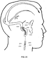
- a first view of a patient's head illustrates that the endovascular shunt devices and stents described herein can be delivered to a preferred location 102 of placement in the medial wall of the sigmoid sinus 104 of the venous system 110 of a patient 108.
- the shunt devices and stents described herein can be delivered to the other large diameter dural venous sinuses disclosed herein: the transverse sinus, straight sinus, or sagittal sinus shown in Fig. 1 .
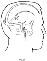
- a second view of the patients head illustrates that in general, the endovascular shunt devices can be delivered to the right or left sigmoid sinus 12A, 12B of a patient's skull 10 via either the right or left jugular vein, respectively, of the venous system.
- the sigmoid sinus lumen 12 is located between the temporal bone ( Figs. 4-6 ) and the cerebellum.
- a shunt 20 is implanted into a sigmoid sinus wall 16, so that one end communicates with CSF located in the cistern or CSF space 18 around the cerebellum 19.
- the device of the present disclosure uses the body's natural disease control mechanisms by delivering the CSF from cistern 18 into sigmoid sinus lumen 12 of the venous system.
- the venous system of the patient can be accessed either through the femoral or jugular veins (not shown) percutaneously. It should be appreciated that the shunt device of the present disclosure can be delivered to the sigmoid sinus via other veins.
- one embodiment of the endovascular CSF shunt 20 of the present disclosure includes opposed first and second ends 22, 24.
- a one-way valve 26 is located at first end 22.
- CSF can travel through shunt 20 and out end 22, however, other fluid (e.g., blood) cannot enter the shunt from open end 22.
- a helical tip 30 is located at second end 24. As will be described further herein, helical tip 30 has a closed sharpened end 31 that is adapted to penetrate sinus wall 16. Tip 30 includes a plurality of apertures 34 through which the CSF enters the tip. A hollow passageway 32 extends from tip 30 and open end 22, such that the CSF fluid entering through apertures 34 can pass through valve 26 and pass from an outlet 36.
- a delivery catheter 40 is delivered to the venous system proximate the brain via the femoral or jugular vein.
- Catheter 40 is inserted into sigmoid sinus lumen 12 at a proximal location 13 toward the neck and inserted toward a distal end 15, which is toward the brain.
- Delivery catheter 40 includes a second lumen 44 and a shunt delivery port 42.
- Lumen 44 directs the entire catheter to the correct location with for example, a guide wire, to allow injection of intravenous contrast to visualize the venous lumen.
- Lumen 44 also supports balloons 46 that can be deployed to temporarily occlude venous flow during stunt implantation.
- Shunt 20 is positioned at an end of an internal catheter 48 that is manipulated through catheter 40 and port 42. To prevent thrombosis within the sigmoid sinus and around the endovascular shunt, shunt 20 can be provided with an anti-thrombic coating.
- catheter 48 facilitates twisting of shunt 20 so that it penetrates through sigmoid sinus wall 12.
- Catheter 48 includes a hollow lumen to allow CSF withdrawal after shunt penetration of the sigmoid sinus wall to confirm that CSF is flowing through the shunt.
- catheter 48 must be rigid enough to allow twisting of the shunt such that it penetrates the sigmoid sinus wall.
- helical tip 30 extends into cistern 18 and CSF located therein.
- a projection 28 located on shunt 20 between the ends abuts the wall and prevents the shunt from passing therethrough.
- internal catheter 48 is detached. The CSF can also be aspirated back prior to detachment of catheter 48.
- shunt 20 is implanted as shown in Fig. 6 .
- CSF 50 draining from outlet 36 from CSF space 18 is delivered to the venous blood flow 17 where it mixes with the blood and passes through the blood stream
- shunt 20 can incorporate different tips at its end and different mechanisms for penetrating the dura.
- the endovascular CSF shunt devices described herein can be placed into a patient percutaneously via a catheter inserted into the venous system of the body through a needle hole, without the need for open surgery, creating a burr hole in the skull, or passing a catheter through cerebellum to access a CSF-filled ventricle.
- the device can be inserted without general anesthesia, which is not possible with current cerebrospinal fluid shunts.
- the device also will allow for more physiologic drainage of cerebrospinal fluid since the device is shunting cerebrospinal fluid into the same cerebral venous system that occurs naturally in normal people.
- Specialized stabilization devices and delivery guide catheters have also been developed to facilitate implantation and stabilization of endovascular cerebral spinal fluid shunt (eCSFS) devices within the sigmoid sinus, transverse sinus, straight sinus, or sagittal sinus of a patient.
- eCSFS endovascular cerebral spinal fluid shunt
- an eCSFS device which is implanted in a wall of the sigmoid sinus of a patient or other sinus described herein can migrate (e.g., dislodge) from the wall, degrading the ability of the eCSFS device to drain cerebral spinal fluid from the patient's subarachnoid space.
- a stent-like device is used to anchor the eCSFS device into the wall of the aforementioned sinus and to provide a platform to prevent migration of the eCSFS device after deployment.
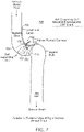
- a stent 700 is implemented as a self-expanding coil, which is coupled to an eCSFS device 702.
- the eCSFS device 702 includes a hollow-pointed perforated cannula 703, a platform 705 including a flow control mechanism (e.g., a one-way valve), and a drainage tube 707.
- the stent 700 is deployed within the sigmoid sinus 704 of a patient with the hollow-pointed cannula 703 inserted through the wall of the sigmoid sinus 704, through the arachnoid layer 706, and into the patient's subarachnoid space 708.
- CSF in the subarachnoid space 708 passes through the perforations in the hollow-pointed cannula 703, through the flow regulation mechanism in the platform 705, and out of the drainage tube 707 into the sigmoid sinus 704.
- the self-expanding coil type stent 700 is a coiled, spring-like member (e.g., a fine platinum or nitinol wire spring) which, when deployed, applies a constant outward radial force against the sigmoid sinus wall such that the stent 700 is anchored in place within the sigmoid sinus 704 by compressive force. Since the eCSFS device 702 is coupled to the stent 700, the stent 700 acts to anchor the eCSFS device 702 in place.
- a coiled, spring-like member e.g., a fine platinum or nitinol wire spring
- the outward radial force applied by the stent 700 presses the eCSFS device 702 against the sigmoid sinus wall, thereby further stabilizing the position of the eCSFS device 702 in the sigmoid sinus wall.
- the stent 700 is first compressed (e.g., by twisting the coiled, spring-like member to reduce its diameter) and then loaded into a delivery catheter.
- the delivery catheter is endovascularly guided to a desired location in the sigmoid sinus 704 or other sinus described herein.
- the compressed stent is released into the sigmoid sinus 704, causing the stent to decompress.
- the diameter of the stent increases until the stent 700 conforms to the inner surface of the sigmoid sinus 704.
- the decompression of the stent 700 is not sufficiently forceful to push the hollow-pointed cannula 703 through the wall of the sigmoid sinus 704 and through the arachnoid layer 706.
- a force generating actuator e.g., a balloon
- the delivery catheter is inserted into the coils 710 of the stent 700, such that when expanded, the hollow-pointed cannula 703 is forced through the wall of the sigmoid sinus 704, through the arachnoid layer 706, and into the subarachnoid space 708.
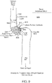
- a stent 800 is implemented as a self- expanding circular basket, which is coupled to an eCSFS device 802.
- the eCSFS device 802 includes a hollow-pointed perforated cannula 803, a platform 805 including a flow control mechanism (e.g., a one-way valve), and a drainage tube 807.
- the stent 800 is deployed within the sigmoid sinus 804 of a patient with the hollow-pointed cannula 803 inserted through the wall of the sigmoid sinus 804, through the arachnoid layer 806, and into the patient's subarachnoid space 808.
- cerebrospinal fluid in the subarachnoid space 808 passes through the perforations in the hollow-pointed cannula 803, through the flow regulation mechanism in the platform 805, and out of the drainage tube 807 into the sigmoid sinus 804.
- the stent 800 includes multiple collapsible tines 810 (e.g., thin platinum or nitinol wires) interconnected by webs 812 in a configuration similar to the support ribs of an umbrella.
- the end of each tine 810 includes a barbed tip 814.
- the tines 810 of the stent 810 make contact with the inner surface of the sigmoid sinus wall and the barbs 814 collectively anchor the stent 800 to the sigmoid sinus wall, thereby preventing the stent 800 and the eCSFS device 802 from becoming dislodged.
- the tines 810 of the stent 800 are first collapsed in a manner similar to closing an umbrella and the collapsed stent 800 is loaded into a delivery catheter.
- the delivery catheter is endovascularly guided to a desired location in the sigmoid sinus 804 or other sinus described herein.
- the collapsed stent 800 is released into the sigmoid sinus 804, wherein the tines 810 of the stent 800 open in a manner similar to an umbrella opening.
- the barbed tips 814 of the tines 810 make contact with and latch into the inner surface of the sigmoid sinus 804, anchoring the stent 800 in place.
- the opening of the tines 810 of the stent 800 does not push the hollow-pointed cannula 803 through the wall of the sigmoid sinus 804 and through the arachnoid layer 806.
- a force generating actuator e.g., a balloon
- the delivery catheter is provided by the delivery catheter and positioned adjacent to the hollow pointed cannula 803, such that when expanded, the hollow-pointed cannula 803 is forced through the wall of the sigmoid sinus 804, through the arachnoid layer 806, and into the subarachnoid space 808.
- a stent 900 is implemented as a self- expanding circumferential type stent, which is coupled to an eCSFS device 902.
- the eCSFS device 902 includes a hollow-pointed perforated cannula 903, a platform 905 including a flow control mechanism (e.g., a one-way valve), and a drainage tube 907.
- the stent 900 is deployed within the sigmoid sinus 904 of a patient with the hollow-pointed cannula 903 inserted through the wall of the sigmoid sinus 904, through the arachnoid layer 906, and into the patient's subarachnoid space 908.
- cerebrospinal fluid in the subarachnoid space 908 passes through the perforations in the hollow-pointed cannula 903, through the flow regulation mechanism in the platform 905, and out of the drainage tube 907 into the sigmoid sinus 904.
- the stent 900 has the form of a mesh tube (e.g., a tubular mesh of fine platinum or nitinol wire) which, when expanded, conforms to an inner surface of the sigmoid sinus 904.
- the expanded stent 900 applies a constant outward radial force against the sigmoid sinus wall such that the stent 900 is anchored in place within the sigmoid sinus 904 by compressive force. Since the eCSFS device 902 is coupled to the stent 900, the stent 900 also acts to anchor the eCSFS device 902 in place.
- the outward radial force applied by the stent 900 presses the eCSFS device 902 against the sigmoid sinus wall, thereby further stabilizing the position of the eCSFS device 902 in the sigmoid sinus wall.
- the stent 900 is first compressed to reduce its diameter and fitted onto a force generating actuator (e.g., a balloon) provided by the delivery catheter.
- a force generating actuator e.g., a balloon
- the delivery catheter is endovascularly guided to a desired location in the sigmoid sinus 904 or other sinus described herein.
- the balloon of the delivery catheter is caused to expand, thereby expanding the stent 900 such that it conforms to the inner surface of the sigmoid sinus 904.
- the expansion of the balloon also forces the hollow-pointed cannula 903 through the wall of the sigmoid sinus 904, through the arachnoid layer 906, and into the subarachnoid space 908.
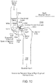
- a stent 1000 is implemented as a self-expanding coil type stent which includes a number of individual coils 1010 interconnected by one or more connecting members 1012 and coupled to an eCSFS device 1002.
- the eCSFS device 1002 includes a hollow-pointed perforated cannula 1003, a platform 1005 including a flow control mechanism (e.g., a one-way valve), and a drainage tube 1007.
- a flow control mechanism e.g., a one-way valve
- the stent 1000 is deployed within the sigmoid sinus 1004 of a patient with the hollow-pointed cannula 1003 inserted through the wall of the sigmoid sinus 1004, through the arachnoid layer 1006, and into the patient's subarachnoid space 1008.
- cerebrospinal fluid in the subarachnoid space 1008 passes through the perforations in the hollow-pointed cannula 1003, through the flow regulation mechanism in the platform 1005, and out of the drainage tube 1007 into the sigmoid sinus 1004.
- the individual coils 1010 of the stent 1000 are fine platinum or nitinol wire coils, which can expand to conform to an inner surface of the sigmoid sinus 1004.
- the coils 1010 of the stent 1000 apply a constant outward radial force against the sigmoid sinus wall such that the stent 1000 is anchored in place within the sigmoid sinus 1004 by compressive force. Since the eCSFS device 1002 is coupled to the stent 1000, the stent 1000 also acts to anchor the eCSFS device 1002 in place.
- the outward radial force applied by the stent 1000 presses the eCSFS device 1002 against the sigmoid sinus wall, thereby further stabilizing the position of the eCSFS device 1002 in the sigmoid sinus wall.
- the stent 1000 is first compressed, including compressing each of the coils 1010 of the stent 1000 to reduce its diameter.
- the compressed stent 1000 is then loaded into a delivery catheter.
- the delivery catheter is endovascularly guided to a desired location in the sigmoid sinus 1004 or other sinus described herein.
- the compressed stent 1000 is released into the sigmoid sinus 1004, allowing the stent 1000, including the coils 1010 to decompress.
- the diameter of the coils 1010 increases until the coils 1010 conform to the inner surface of the sigmoid sinus 1004 at the delivery location.
- the decompression of the stent 1000 is not sufficiently forceful to push the hollow-pointed cannula 1003 through the wall of the sigmoid sinus 1004 and through the arachnoid layer 1006.
- a force generating actuator e.g., a balloon
- the delivery catheter is inserted into the coils 1010 of the stent 1000 such that when expanded, the hollow-pointed cannula 1003 is forced through the wall of the sigmoid sinus 1004, through the arachnoid layer 1006, and into the subarachnoid space 1008.
- one or more of the stents described above include a port structure attached to the stent.
- the port enables subsequent repositioning or revision of the cannula and/or flow control mechanism of the eCSFS device. That is, a stent guided stable port is first established between the sigmoid sinus (or other sinus described herein) and the intradural subarachnoid space.
- the port incorporates a self-sealing port to enable replacement of any cannula and/or flow control mechanisms without leaving an open puncture site between the sigmoid sinus and the subarachnoid space.
- the port system obviates the need for multiple repeated punctures, especially when a cannula and/or flow control mechanism requires replacement.
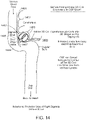
- a self-expanding circumferential type stent 1100 is deployed within the sigmoid sinus 1104 of a patient.
- a self-sealing port 1105 is mounted on the stent 1100 in such a way that the port 1105 is held against an inner surface of the patient's sigmoid sinus 1104.
- An expanded view 1107 of the port 1105 shows that, in some examples, the port 1105 includes a self-sealing, penetrable, antithrombotic membrane 1113 surrounded by a ring 1109.
- the membrane 1113 is penetrable due to a number of slits 1111 which are cut through the membrane 1113.
- the slits 1111 are cut in such a way (e.g., a spiral cut resembling that of a camera leaf shutter) that they sealingly close around any object inserted into the port 1105 and are sealingly closed when no object is inserted in the port 1105.
- the membrane 1113 is a solid elastic membrane (e.g., silastic or a silicone based alternative) which, upon penetration by an object (e.g., an eCSFS device), forms a seal around the object and, upon removal of the object, reseals itself.
- the membrane 1113 is fabricated using a material with inherent antithrombotic properties.
- the membrane 1113 includes an antithrombotic coating.
- the ring 1109 is fabricated from material such as nitinol or platinum, possibly decorated with radiopaque material markers made of gold or tantalum or another suitably radiopaque material.
- the ring 1109 includes, on its outer side, facing the inner surface of the patient's sigmoid sinus 1104, a groove with a hydrogel gasket (not shown) disposed therein. The outer side of the ring 1109 including the hydrogel gasket makes contact with the inner surface of the patient's sigmoid sinus 1104. Upon contact with sigmoid sinus blood, the hydrogel gasket swells, providing a hermetic seal that prevents sigmoid sinus blood from flowing around the port 1105 into the intracranial space.
- a self-expanding coil type stent 1200 including a self-sealing port 1205 is deployed within the sigmoid sinus 1204 of a patient.
- An eCSFS device 1213 e.g., a corkscrew type eCSFS device
- the eCSFS device 1213 can be removed and replaced without having to create another puncture site at a different location in the patient's sigmoid sinus wall.
- the port 1205 ensures that fluid passes only through the eCSFS device 1213 and does not leak into or out of the subarachnoid space through the puncture site.
- the port is deployed in a patient's sigmoid sinus with an eCSFS device already installed within the port apparatus. In other examples, the port is deployed in the patient's sigmoid sinus without an eCSFS device installed through the port and the eCSFS device is installed through the port in a later step.
- the stent devices described above may include slots or multiple miniature barbs which act to prevent migration of the stent within the smooth sinus endothelial layer of the sigmoid, transverse, straight, or sagittal sinus during and/or after deployment.
- the surface of the stent may be treated such that its outer wall is abrasive and prevents slippage within the smooth endothelial layer during and/or after deployment.
- the stent devices described above are retrievable or repositionable after deployment.
- the stent devices are constructed with an umbrella like mesh, providing the benefit of catching any foreign material that may be liberated or released by deployment of the eCSFS device.
- the umbrella like mesh is retrievable through a specialized guide catheter.
- one or more of the stents described above includes a deployment mechanism including a controllable central sharp spicule that is hollow such that it allows passage of cerebrospinal fluid.
- This mechanism will enable the perforation of the sigmoid, transverse, straight, or sagittal sinus wall and while also allowing for the spicule to be retracted into the device and removed if necessary.
- the spicule, included in an eCSFS device is inserted through a stent mounted, self-sealing port structure (as described above) and is held in place by friction in the self-sealing port structure.
- the eCSFS device including the spicule could be grabbed with an endovascular snare and pulled out of the self-sealing port structure and into the venous system.
- eCSFS device is described as having a corkscrew type intracranial aspect.
- eCSFS devices have been developed which allow safe placement of the device, stability of the device, penetration through the dura and arachnoid, apposition of the arachnoid to the dura after device deployment, and slight displacement of the brain parenchyma (e.g., the cerebellar cortex) so that it does not clog the device.
- brain parenchyma e.g., the cerebellar cortex
- a corkscrew type self-anchoring eCSFS device 1302 (similar to the corkscrew shaped shunt described above) includes a corkscrew shaped perforated cannula 1303, a platform 1305 including a flow regulation mechanism (not shown), and a drainage tube 1307.
- the corkscrew-shaped cannula 1303 In its deployed state, the corkscrew-shaped cannula 1303 is inserted through a sigmoid sinus wall, through the arachnoid layer 1306, and into the subarachnoid space 1308 of a patient. Cerebrospinal fluid flows through the perforations of the corkscrew shaped cannula 1303, through the flow control mechanism in the platform 1305, and out of the drainage tube 1307 with the flow control mechanism controlling the flow of cerebrospinal fluid.
- the eCSFS device 1302 is first loaded into a delivery catheter.
- the delivery catheter endovascularly guides the eCSFS device 1302 to a desired deployment location in the sigmoid sinus 1304.
- the tip of the corkscrew type self-anchoring eCSFS device 1302 is pressed into a wall of the sigmoid sinus 1304 and the eCSFS device 1302 is rotated such that the corkscrew shaped cannula 1303 passes through with wall of the sigmoid sinus 1304 with a screw-like motion until the platform 1305 rests against the wall of the sigmoid sinus 1304 (or other sinus described herein).
- the delivery catheter is withdrawn from the patient.
- the eCSFS device 1302 resists withdrawal from sigmoid sinus wall due to the corkscrew shape of its cannula 1303.
- a three-dimensional coil type self-anchoring eCSFS device 1402 includes a section of coiled three-dimensional-shaped perforated microcatheter tubing 1403 with a pre-defined three-dimensional coil shape, a platform 1405 including a flow regulation mechanism (e.g., a one-way valve), and a drainage tube 1407.
- the perforated tubing 1403 is disposed through a sigmoid sinus wall and into the subarachnoid space 1408 of a patient, between the brain parenchyma 1409 and the arachnoid layer 1406. Cerebrospinal fluid flows through the perforations of the tubing 1403, through the flow control mechanism in the platform 1405, and out of the drainage tube 1407 with the flow regulation mechanism controlling the flow of cerebrospinal fluid.
- the three-dimensional shape of the tubing 1403 presses against the arachnoid layer 1406, causing the platform 1405 to be pulled tight against the wall of the sigmoid sinus 1404.
- This pulling of the platform 1405 by the tubing 1403 pinches the sigmoid sinus wall and the arachnoid layer 1406 between the platform 1405 and the tubing 1403, anchoring the eCSFS device 1402 in place.
- the three-dimensional shape of the tubing 1403 pushes against the brain parenchyma 1409 to create a space for cerebrospinal fluid to pool around the tubing 1403.
- at least some portions of the tubing 1403, along with the perforations in the tubing are not in contact with the brain parenchyma 1409.
- the portions of the tubing 1403 not in contact with the brain parenchyma 1409 are less likely to become occluded and provide a consistently open, low resistance passageway for cerebrospinal fluid to flow through the valve and out of the drainage tube 1407.
- the tubing 1403 of the device 1402 is first straightened out and loaded into a delivery catheter.
- the delivery catheter is endovascularly guided to a desired location in the sigmoid sinus 1404 or other sinus described herein.
- the tubing 1403 is pressed through the wall of the sigmoid sinus 1404, through the arachnoid layer 1406, and into the subarachnoid space 1408.
- the tubing 1403 is made from a material with shape memory properties such as nitinol (i.e., nickel titanium).
- the tubing reverts to its original, predefined three-dimensional coil shape, pushing against the brain parenchyma 1409 as is described above.
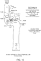
- an umbrella type self-anchoring eCSFS device 1502 includes an umbrella shaped screen 1511 covering a perforated hollow cannula 1503, a platform 1505 including a flow regulation mechanism (e.g., a one-way valve), and a drainage tube 1507.
- a flow regulation mechanism e.g., a one-way valve
- the perforated hollow cannula 1503 and the umbrella shaped screen 1511 are disposed through a sigmoid sinus wall into the subarachnoid space 1408 of a patient, between the brain parenchyma 1509 and the arachnoid layer 1506.
- Cerebrospinal fluid flows through the perforations of the cannula 1503, through the flow regulation mechanism in the platform 1505, and out of the drainage tube 1507 into the sigmoid sinus 1504 with the flow regulation mechanism controlling the flow of cerebrospinal fluid.
- the umbrella shaped screen 1511 presses against the arachnoid layer 1506, causing the platform 1505 to be pulled tight against the wall of the sigmoid sinus 1504. This pulling of the platform 1505 by the umbrella shaped screen 1511 pinches the sigmoid sinus wall and the arachnoid layer 1506 between the platform 1505 and the umbrella shaped screen 1511, anchoring the eCSFS device 1502 in place.
- the umbrella shaped screen 1511 pushes against the brain parenchyma 1509 to create a space for cerebrospinal fluid to pool around the perforated hollow cannula 1503.
- the umbrella shaped screen 1511 prevents the brain parenchyma 1509 from making contact with and occluding the perforations in the perforated hollow cannula 1503, thereby maintaining a consistently open, low resistance passageway for cerebrospinal fluid to flow through the valve and out of the drainage tube 1507.
- the umbrella shaped screen 1511 is collapsed in a manner similar to an umbrella being collapsed and the device 1502 is loaded into a delivery catheter.
- the delivery catheter is endovascularly guided to a desired location in the sigmoid sinus 1504 or other sinus described herein. Once the delivery catheter including the device 1502 reaches the desired location, the perforated hollow cannula 1503 and the collapsed umbrella shaped screen 1511 are pressed through the wall of the sigmoid sinus 1504, through the arachnoid layer 1506, and into the subarachnoid space 1508.
- the umbrella shaped screen 1511 is made from a material with shape memory properties such as nitinol (i.e., nickel titanium).
- shape memory properties such as nitinol (i.e., nickel titanium).
- the umbrella shaped screen 1511 opens to its original, predefined umbrella shape, pushing against the brain parenchyma 1509 as described above.
- the umbrella shaped screen 1511 is mechanically opened by an endovascular surgeon operating the delivery catheter.
- the umbrella type self-anchoring eCSFS device 1502 can be included as part of one or more of the stents described above.
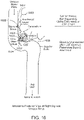
- a globe type self-anchoring eCSFS device 1602 includes a multi-filament globe-like assembly 1611 surrounding a perforated hollow cannula 1603, a platform 1605 including a flow regulation mechanism (e.g., a one-way valve), and a drainage tube 1607.
- a flow regulation mechanism e.g., a one-way valve
- the perforated hollow cannula 1603 and the multi-filament globe-like assembly 1611 are disposed through a sigmoid sinus wall into the subarachnoid space 1608 of a patient, between the brain parenchyma 1609 and the arachnoid layer 1606.
- Cerebrospinal fluid flows through the perforations of the cannula 1603, through flow regulation mechanism in the platform 1605, and out of the drainage tube 1607 into the sigmoid sinus 1605 with the flow regulation mechanism controlling the flow of cerebrospinal fluid.
- the multi-filament globe-like assembly 1611 presses against the arachnoid layer 1606, causing the platform 1605 to be pulled tight against the wall of the sigmoid sinus 1605.
- This pulling of the platform 1605 by the multi-filament globe-like assembly 1611 pinches the sigmoid sinus wall and the arachnoid layer 1606 between the platform 1605 and the multi-filament globe-like assembly 1611, anchoring the eCSFS device 1602 in place.
- the multi-filament globe-like assembly 1611 pushes against the brain parenchyma 1609 to create a space for cerebrospinal fluid to pool around the perforated hollow cannula 1603.
- the multi-filament globe-like assembly 1611 prevents the brain parenchyma 1609 from making contact with and occluding the perforations in the perforated hollow cannula 1603, thereby maintaining a consistently open, low resistance passageway for cerebrospinal fluid to flow through the valve and out of the drainage tube 1607.
- the multi-filament globe-like assembly 1611 can be made in different sizes and different shapes with different radial strengths.
- the filaments of the globe-like assembly 1611 are first compressed and the device 1602 is loaded into a delivery catheter.
- the delivery catheter is endovascularly guided to a desired location in the sigmoid sinus or other sinus described herein.
- the compressed globe-like assembly 1611 and the perforated hollow cannula 1603 are pressed through the wall of the sigmoid sinus, through the arachnoid layer, and into the subarachnoid space.
- the filaments of the globe-like assembly 1611 are made from a material with shape memory properties such as nitinol (i.e., nickel titanium).
- the globe-like assembly 1611 is gradually unsheathed, allowing the filaments of the globe-like assembly 1611 to return to their original, predefined globe-like shape, pushing against the brain parenchyma as described above.
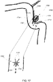
- FIG. 17 another example of a globe type self-anchoring eCSFS device 1702 includes a multi-filament globe-like assembly 1711 surrounding a perforated hollow cannula 1703, a number of radial struts 1705, a platform 1709 including a flow regulation mechanism (e.g., a one-way valve), and a drainage tube 1707.
- a flow regulation mechanism e.g., a one-way valve
- the perforated hollow cannula 1703 and the multi-filament globe-like assembly 1711 are disposed through a sigmoid sinus wall into the subarachnoid space 1708 of a patient, between the brain parenchyma (not shown) and the arachnoid layer 1706.
- Cerebrospinal fluid flows through the perforations of the cannula 1703, through the flow regulation portion in the platform 1709 and out of the drainage tube 1707 into the sigmoid sinus 1704 with the flow regulation mechanism controlling the flow of cerebrospinal fluid.
- the multi-filament globe-like assembly 1711 presses against the arachnoid layer 1706, causing the platform 1709 and the radial struts 1705 to be pulled tight against the wall of the sigmoid sinus 1705.
- This pulling of the platform 1709 and the radial struts 1705 by the multi-filament globe-like assembly 1711 pinches the sigmoid sinus wall and the arachnoid layer 1706 between the multi-filament globe-like assembly 1711 and the platform 1079 and radial struts 1705, anchoring the eCSFS device 1702 in place.
- the filaments, including the radial struts 1705 of the globe-like assembly 1711 are first compressed and the device 1702 is loaded into a delivery catheter.
- the radial struts 1705 are in a straightened state where they extend along an axial direction of the eCSFS device 1702 rather than along a radial direction of the eCSFS device 1702.
- the delivery catheter is endovascularly guided to a desired location in the sigmoid sinus 1704 or other sinus described herein.
- the compressed globe-like assembly 1711 and the perforated hollow cannula 1703 are pressed through the wall of the sigmoid sinus, through the arachnoid layer, and into the subarachnoid space.
- the filaments of the globe-like assembly 1711, including the radial struts 1705 are made from a material with shape memory properties such as nitinol (i.e., nickel titanium). In such examples, once the globe-like assembly is fully fed into the subarachnoid space (or shortly thereafter), the globe-like assembly 1711 is gradually unsheathed.
- the filaments of the globe-like assembly 1711 are allowed to return to their original, predefined globe-like shape, pushing against the brain parenchyma as described above.
- the radial struts 1705 return to their original, predefined radially extending shape, pinching the sigmoid sinus wall between the radial struts 1705 and the globe-like assembly.
- the globe-like assembly 1711 is forced into its original, globe-like, shape by a surgeon (or another operator) pulling on a filament such as a wire which is attached to the top of the globe.
- the eCSFS device 1702 includes a mesh or screen-like material which surrounds some or all of the globe-like assembly 1711, thereby preventing brain parenchyma from entering the globe-like assembly 1711 where it could potentially occlude the perforations of the cannula 1703.
- one or more of the eCSFS devices described above includes a self-sealing mechanism which prevents sinus blood (i.e., from the sigmoid, transverse, straight, or sagittal sinus) from flowing around the platform of the device into the intracranial space.
- the platform of the device may include a groove formed in its surface facing the sigmoid sinus wall and a hydrogel gasket disposed within the groove. Upon contact with sigmoid sinus blood, the hydrogel gasket swells, providing a hermetic seal which prevents sigmoid sinus blood from flowing around the platform and into the intracranial space.
- the drainage tube of the eCSFS devices described above may extend along the internal jugular vein for a certain length, effectively mimicking a ventriculo-atrial shunt.
- drainage tube of the eCSFS devices described above may be sufficiently distant from the venous sinus wall to prevent its incorporation and subsequent endothelialization in to the wall, which would result in occlusion of the eCSFS device.
- the dimensions of the intracranial portions of the eCSFS devices described above are in the range of 3 mm to 1.5cm.
- the portions of the eCSFS devices described above which are located in the sigmoid sinus lumen have a dimension of approximately 2mm to 4mm.
- the length of the drainage tubes of the eCSFS devices described above is configurable such that it reaches the superior vena cava and right atrial junction.
- the eCSFS devices described herein have a length in the range of 4 to 5 centimeters.
- the eCSFS devices (and in particular, the drainage tube and the flow regulation mechanism) have a minimum diameter of 0.5mm to minimize occlusion of the device by plaque, protein clots, and/or blood clots.
- the eCSFS devices are safe for use in a magnetic resonance imaging (MRI) machine.
- MRI magnetic resonance imaging
- the eCSFS devices are removable and/or adjustable using a loop or snare device.
- multiple eCSFS devices can be placed adjacently (i.e., within 1 mm to 5 mm) in the sigmoid sinus.
- the platforms of the eCSFS devices described herein is made of a material with shape memory properties such as nitinol (i.e., nickel titanium).
- portions of the eCSFS device which are deployed in the lumen of the sigmoid sinus are coated in an anticoagulant material such as heparin to prevent clotting of blood in, on, and around the portions of the eCSFS device.
- an anticoagulant material such as heparin
- the eCSFS device includes a mechanism for detecting whether cerebrospinal fluid is flowing through the device and wirelessly communicating that information to a technician.
- the platform or the cannula of the device may include a flow sensor which senses whether cerebrospinal fluid is flowing through the device and, in some examples, the flow rate of cerebrospinal fluid.
- Data collected using the flow sensor can be provided to wireless communication circuitry in the device which, upon request, wirelessly communicates the flow sensor data out of the patient's body to a communication device operated by the technician.
- the device may include RFID circuitry which is temporarily energized by radio frequency energy provided from outside of the patient's body. Once energized, the RFID circuitry uses the flow sensor to collect data related to the flow of cerebrospinal fluid through the device. The RFID circuitry then transmits the collected data out of the patient's body using radio frequency communications before it runs out of energy.
- the flow regulation valve in the platform of the device can be controlled (e.g., turned on, turned off, or adjusted) from outside of the patient's body (e.g., by using for example a magnet).
- the length of the drainage tube extending from the platform into the venous system can be controlled as can be the diameter of the perforations in the hollow cannula in order to affect the rate of flow of cerebrospinal fluid into the shunt.
- a pressure gradient across the eCSFS device can be regulated by the use of valves with different pressure settings.
- the eCSFS devices described above are designed with an optimal flow rate of approximately 10 cubic centimeters (cc) of cerebrospinal fluid per hour (i.e., 200 cc - 300 cc per 24 hour period).
- the eCSFS devices described above are designed to allow continuous flow of cerebrospinal fluid. In other examples, the eCSFS devices described above are designed for intermittent flow of cerebrospinal fluid.
- all of the eCSFS devices described above include flow regulation mechanism such as a one-way valve.
- delivery of an eCSFS device may require a catheterization apparatus that is specially designed for implantation of the eCSFS device in the sigmoid, transverse, straight, or sagittal sinus.
- a catheterization apparatus that is specially designed for implantation of the eCSFS device in the sigmoid, transverse, straight, or sagittal sinus.
- some patients such as those with a contralateral sinus stenosis or occlusion have a compromised alternative venous pathway.
- full occlusion of the sigmoid sinus by, for example, a balloon guide of a guide catheter might severely reduce or completely inhibit venous drainage of the cerebral tissue.
- Such a reduction in venous drainage for an extended period of time such as the time required to implant an eCSFS device is potentially dangerous for the patient.
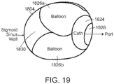
- a catheterization apparatus 1820 includes a guide catheter 1822, a delivery catheter 1824, and two (or more) stabilization balloons 1826a, 1826b.
- the guide catheter 1822 is used to endovascularly guide the catheterization apparatus 1820 to the sigmoid sinus 1804 (or other sinus described herein). While the catheterization apparatus 1820 is being guided to the delivery location, the stabilization balloons 1826a, 1826b are deflated.
- the stabilization balloons 1826a, 1826b are inflated, stabilizing the catheterization apparatus 1820 at the delivery location and causing an opening 1828 of the delivery catheter 1824 to be positioned against an inner surface of a patient's sigmoid sinus 1804.
- FIG. 19 a cross-sectional view of the end of the catheterization apparatus 1820 of FIG. 18 is shown.
- the catheterization apparatus 1820 is located within the sigmoid sinus 1804 with its stabilization balloons 1826a, 1826b inflated and the opening 1828 of the delivery catheter 1824 positioned against the inner surface of the patient's sigmoid sinus 1804. Due to the use of two (or more) stabilization balloons 1826a, 1826b, a significant portion 1830 of the lumen of the sigmoid sinus 1804 remains unoccluded, allowing for the passage of blood through the sigmoid sinus 1804 during the eCSFS device implantation procedure.
- an eCSFS device 2002 is threaded through the delivery catheter 1824, through the opening 1828 of the delivery catheter 1824, and penetrates through the wall of the sigmoid sinus 1803 through the arachnoid layer 2006, and into the subarachnoid space 2008.
- the filaments 2011 of the eCSFS device 2002 (a globe-type eCSFS device in this case) are allowed to return to their original, predefined globe-like shape, pushing against the brain parenchyma.
- the radial struts 2005 return to their original, predefined radially extending shape, pinching the sigmoid sinus wall between the radial struts 2005 and the globe-like assembly.
- a surgeon can confirm that the eCSFS device 2002 is working by aspirating cerebrospinal fluid through a drainage tube 2134 that is within the delivery catheter 1824 and attached to the eCSFS device 2002.
- the stabilization balloons 1826a, 1826b are deflated and the drainage tube 2134 is detached (e.g., by electrolytic detachment) at a detachment point 2132.
- the catheterization apparatus 1820 is withdrawn, completing the eCSFS implantation procedure.
- a catheterization apparatus 2320 has a female receptacle 2334 mounted on one or more of the stabilization balloons 2326 and attached to a drainage catheter 2336 of the catheterization apparatus 2320.
- the catheterization apparatus 2320 is navigated to the site of the eCSFS device 2302 and the female receptacle 2334 is sealingly placed over the drainage tube 2307 of the eCSFS device 2302.
- a surgeon attempts to draw cerebrospinal fluid through the eCSFS device and into the drainage catheter 2336. If cerebrospinal fluid is successfully drawn through the eCSFS device 2302, then the eCSFS device 2302 is open. Otherwise, the eCSFS device 2302 is occluded.
- the eCSFS device includes a radiopaque material that aids in guiding the catheterization apparatus 2320 to the delivery location and placing the female receptacle 2334 over the drainage tube 2307 of the eCSFS device 2302.
- the catheterization apparatus includes a steerable component in order to maintain the working port of the guide catheter in direction parallel to with the intracranial surface of the sigmoid sinus.
- the catheterization apparatus in order to evaluate a proximity of the eCSFS device to the sigmoid sinus wall and to evaluate the dural and arachnoid layers separating the device from the cerebrospinal fluid, includes a phased array ultrasound micro catheter.
- the catheterization apparatus in order to evaluate a proximity of the eCSFS device to the sigmoid sinus wall and to evaluate the dural and arachnoid layers separating the device from the cerebrospinal fluid, includes an OCT (optical coherence tomography) micro catheter imaging device.
- OCT optical coherence tomography
- the opening at the end of the delivery catheter of the catheterization apparatus is specially configured to dock with the stent mounted ports described above.
- the catheterization apparatus may include a temporary stent for stabilizing the delivery catheter and positioning the opening of the delivery catheter against the wall of the sigmoid sinus.
- the catheterization apparatus includes a single stabilization balloon with an asymmetric shape such that the delivery catheter can easily be pushed against a wall of the sigmoid sinus in an area over the puncture site.
- eCSFS devices should be dimensioned and configured to eliminate or minimize any disruption to sinus blood flow and occlusion within the sinus lumen.
- the aforementioned eCSFS deployment sites have been selected with this consideration in mind. That is, the dural venous sinuses described in this application (i.e., sigmoid, transverse, straight, or sagittal sinus) can have a relatively large diameter (e.g., 7 mm, 8 mm, 9 mm or more) compared to other dural venous sinuses.
- the increased sinus diameter accommodates eCSFS devices as described herein, while minimizing the impact of deployment procedures and a deployed device on venous blood flow within the sinus.
- a specialized catheterization apparatus has also been disclosed, which minimizes sinus occlusion during eCSFS deployment to preserve venous drainage of cerebral tissue.
- the subarachnoid portions of the eCSFS device embodiments disclosed herein can include a shielding mechanism that protects the surface of the eCSFS, and in particular any openings in the surface of the eCSFS device that are designed to enable the passage or flow of CSF therethrough, from surrounding brain parenchyma (e.g., cerebellum) with a stent-like, umbrella-type, or equivalent configuration.
- the shielding mechanisms enable continuous CSF flow through the eCSFS device and mitigate clogging by structurally separating brain parenchyma tissue from the portions of the shunt device that are implanted into the subarachnoid space.
- the shielding mechanisms are particularly important if an eCSFS device is not deployed in a well-established subarachnoid cistern or where there is little or no CSF-filled space between the arachnoid layer and the pia.
- the subarachnoid space accessible from the sigmoid sinus can include little or no CSF-filled space (e.g., 0 - 1 mm between arachnoid and pia) to accommodate the subarachnoid portion of an eCSFS device.
- the shielding aspects of the eCSFS devices address this challenge by advantageously creating, augmenting, and/or maintaining a subarachnoid cistern for eCSFS devices in such patients.
Abstract
Description
- The present application relates to shunts capable of draining cerebrospinal fluid to the venous system.
- It is known to treat hydrocephalus by draining cerebrospinal fluid (CSF) from the brain with a drain tube, catheter or shunt. See
U.S. Patent Nos. 5,385,541 and4,950,232 . These known devices are complex and invasive. The risk for infection is also increased due to the complexity of these devices. - The known shunts are limited to areas of placement due to fluid flow control; however, fluid flow still poses difficulties due to the complexity of the devices and the placement areas. Commonly, the shunts/catheters are placed through the skull of the patient. This placement requires an open surgical procedure performed under general anesthesia. The shunts/catheters also require pressure control to facilitate CSF flow. Moreover, the known shunts and methods of placements do not work in conjunction with a body's natural disease control processes.
- Thus, there is a need for an endovascular shunt that can be inserted into the venous system percutaneously, without the need for open surgery and concomitant risk of infection.
- The present disclosure relates to endovascular CSF shunts that drain CSF from the subarachnoid space around the cerebellum into a dural venous sinus. As used in the present disclosure, the phrase "dural venous sinus" and other references to the term "sinus" mean the sigmoid sinus, transverse sinus, straight sinus, or sagittal sinus.
- The present disclosure also relates to methods of draining CSF by inserting, and deploying, and optionally detaching, one or more of the shunts disclosed herein by an endovascular route through the venous system. For example, the venous system may be accessed either through the femoral vein or the jugular vein percutaneously.
- The endovascular cerebrospinal fluid shunt devices as described herein are an improvement over the standard cerebrospinal fluid shunts, because they can be placed into a patient percutaneously via a catheter inserted into the venous system of the body through a needle hole, without the need for open surgery and the skin incisions required with current shunt devices. In some patients, the shunt devices can be inserted without general anesthesia, which is not possible with current cerebrospinal fluid shunts. The shunt devices also will allow for more physiologic drainage of cerebrospinal fluid since the device is shunting cerebrospinal fluid into the same cerebral venous system that occurs naturally in people without impaired CSF drainage.
- One aspect of the present disclosure is to provide implantable shunt devices for draining fluid from a patient's subarachnoid space. The devices include a shunt having opposed first and second ends. The devices also include a one-way valve and a tip configured to penetrate the sinus "wall" (e.g., a wall of dura) to access the subarachnoid space. In some embodiments, a one-way valve is located at the first end of the shunt and a helical tip is disposed at the second end. In use, the helical tip penetrates the sigmoid sinus wall of the patient and a hollow passageway extending between the helical tip and the first end allows the CSF to be drained through the helical tip and out through the valve.
- Another aspect of the present disclosure provides methods for draining cerebrospinal fluid from a patient's subarachnoid space. The methods include providing a shunt having opposed first and second ends, delivering the shunt to the sinus wall, implanting the helical tip in the sinus wall of the patient; and draining cerebrospinal fluid from the patient.
- In another general aspect, implantable shunt devices for draining cerebrospinal fluid from a patient's subarachnoid space include a shunt having opposed first and second ends, the second end being constructed to penetrate a wall of a sinus of the patient, a one-way valve disposed at either end or between the ends of the shunt, a hollow passageway extending the length of the shunt such that cerebrospinal fluid can be drained through the second end, valve, and first end into the sinus lumen. The shunt device can also include a mechanism coupled to the shunt and configured to anchor the shunt at a desired location proximal to the subarachnoid space.
- Aspects may include one or more of the following features in various combinations as indicated in the appended claims.
- The shunt device may be sized and configured to be positioned within the sigmoid sinus, transverse sinus, straight sinus, or sagittal sinus. The shunt device can include a stent device configured for insertion into the sinus of the patient. The stent device can include a helical coil. The helical coil can be self-expanding. The stent device can include a self-expanding basket. The stent device can include a circumferential mesh. The circumferential mesh can be self-expanding. The stent device can include a plurality of individual coils coupled to a connecting member. Each coil of the plurality of coils can be self-expanding.
- The shunt device can include a helical tip configured to be positioned within the subarachnoid space. The shunt device can include a coiled cannula with a three-dimensional shape, wherein the coiled cannula is configured to be positioned within the subarachnoid space. The coiled cannula can be configured to realize its three-dimensional shape upon being positioned within the subarachnoid space. The shunt device can include an umbrella shaped screen configured to be positioned within the subarachnoid space. The umbrella shaped screen can be configured to realize its umbrella shape upon being positioned within the subarachnoid space. The shunt device can include a globe shaped screen configured to be positioned within the subarachnoid space. The globe shaped screen can be configured to realize its globe shape upon being positioned within the subarachnoid space.
- Aspects may include one or more of the following advantages.
- Among other advantages, the portions of the endovascular cerebrospinal fluid shunt (eCSFS) devices that are specifically designed be placed into the cerebral spinal fluid (CSF) space (e.g., the subarachnoid space) can be shielded from the surrounding brain parenchyma (e.g., the cerebellum) by a shielding mechanism, e.g., a stent-like or umbrella-type device, advantageously enabling the continuous flow of cerebral spinal fluid through the device. That is, certain embodiments described herein include shielding mechanisms that reduce or mitigate the potential occlusion of openings in eCSFS devices that are designed to enable the passage of CSF through the device by structurally separating, e.g., pushing back, the brain parenchyma from the subarachnoid portions of the eCSFS device. Additionally, these shielding mechanisms can also create and maintain a space for CSF to pool within the subarachnoid space. Maintaining a well-defined space for CSF to pool around the subarachnoid portion of the eCSFS device ensures that CSF will flow to the venous system and enables the shunt device to operatively maintain normal intracranial pressure by draining excess CSF from the subarachnoid space.
- The use of stents in conjunction with or as a part of the shunt devices described herein results in a better anchoring of eCSFS devices in their desired locations. The use of stents can also simplify the process of delivering and implanting eCSFS devices.
- Use of a radiopaque material to form a ring or other marker for a stent mounted port provides the advantage that the stent mounted port can be easily located using fluoroscopy techniques.
- Use of a specialized catheterization apparatus including two or more stabilization balloons permits passage of blood around the balloon and through the sigmoid sinus, transverse sinus, straight sinus, or sagittal sinus during implantation of an eCSFS device. Since blood is permitted to flow around the stabilization balloons, venous drainage of the cerebral tissue continues during implantation of the eCSFS device.
- These and other features, aspects, and advantages of the present disclosure will become more apparent from the following detailed description relative to the accompanied drawings, in which:
-
-
Fig. 1 is a schematic of an anatomy of the venous system in the skull of a human. -
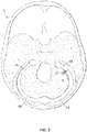
Fig. 2 is a schematic of a top view of a human skull base with the brain removed illustrating the placement of an endovascular shunt penetrating the sigmoid sinus wall into the subarachnoid space. -
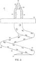
Fig. 3 is a partial cross-section of an embodiment of the endovascular shunt ofFig. 2 . -
Fig. 4 illustrates the delivery of the endovascular shunt ofFig. 3 to the CSF space of a patient's venous system. -
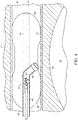
Fig. 5 illustrates the implantation of the endovascular shunt ofFig. 3 into the sigmoid sinus wall. -
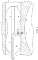
Fig. 6 illustrates the endovascular shunt ofFig. 3 implanted in the sigmoid sinus wall. -
Fig. 7 shows a self-expanding coil type stent disposed within a sigmoid sinus. -
Fig. 8 shows an alternative embodiment of a self-expanding stent disposed within a sigmoid sinus. -
Fig. 9 shows yet another alternative embodiment of a self-expanding stent disposed within a sigmoid sinus. -
Fig. 10 shows a self-expanding coil type stent disposed within a sigmoid sinus. -
Fig. 11 shows a stent-mounted port disposed within a sigmoid sinus. -
Fig. 12 shows a stent-mounted port disposed within a sigmoid sinus and having an endovascular cerebrospinal fluid shunt device inserted therein. -
Fig. 13 shows a corkscrew type self-anchoring endovascular cerebrospinal fluid shunt device. -
Fig. 14 shows three-dimensional coil type self-anchoring endovascular cerebrospinal fluid shunt device. -
Fig. 15 shows an umbrella type self-anchoring endovascular cerebrospinal fluid shunt. -
Fig. 16 shows a first globe type self-anchoring endovascular cerebrospinal fluid shunt device. -
Fig. 17 shows a second globe type self-anchoring endovascular cerebrospinal fluid shunt device. -
Fig. 18 shows a schematic of a catheterization apparatus inserted within a patient's sigmoid sinus with its stabilization balloons inflated. -
Fig. 19 shows a cross-sectional view of the catheterization apparatus ofFig. 18 . -
Fig. 20 shows a schematic of an endovascular cerebrospinal fluid shunt being implanted through the catheterization apparatus. -
Fig. 21 shows the catheterization apparatus after shunt implantation with deflation of the balloon and expansion of the globe in the subarachnoid space. -
Fig. 22 shows the catheterization apparatus being withdrawn from the patient's sigmoid sinus. -
Fig. 23 shows a catheterization apparatus for patency testing. - Referring to
Fig. 1 , a first view of a patient's head illustrates that the endovascular shunt devices and stents described herein can be delivered to apreferred location 102 of placement in the medial wall of thesigmoid sinus 104 of thevenous system 110 of apatient 108. Alternatively, the shunt devices and stents described herein can be delivered to the other large diameter dural venous sinuses disclosed herein: the transverse sinus, straight sinus, or sagittal sinus shown inFig. 1 . - Referring to
Fig. 2 , a second view of the patients head illustrates that in general, the endovascular shunt devices can be delivered to the right or left sigmoid sinus 12A, 12B of a patient'sskull 10 via either the right or left jugular vein, respectively, of the venous system. Thesigmoid sinus lumen 12 is located between the temporal bone (Figs. 4-6 ) and the cerebellum. - A
shunt 20 is implanted into asigmoid sinus wall 16, so that one end communicates with CSF located in the cistern orCSF space 18 around thecerebellum 19. The device of the present disclosure uses the body's natural disease control mechanisms by delivering the CSF fromcistern 18 intosigmoid sinus lumen 12 of the venous system. The venous system of the patient can be accessed either through the femoral or jugular veins (not shown) percutaneously. It should be appreciated that the shunt device of the present disclosure can be delivered to the sigmoid sinus via other veins. - As shown in
Fig. 3 , one embodiment of theendovascular CSF shunt 20 of the present disclosure includes opposed first and second ends 22, 24. A one-way valve 26 is located atfirst end 22. As will be described further herein, CSF can travel throughshunt 20 and outend 22, however, other fluid (e.g., blood) cannot enter the shunt fromopen end 22. - A
helical tip 30 is located atsecond end 24. As will be described further herein,helical tip 30 has a closed sharpenedend 31 that is adapted to penetratesinus wall 16.Tip 30 includes a plurality ofapertures 34 through which the CSF enters the tip. Ahollow passageway 32 extends fromtip 30 andopen end 22, such that the CSF fluid entering throughapertures 34 can pass throughvalve 26 and pass from anoutlet 36. - Referring to
Figs. 4-6 and as described above, adelivery catheter 40 is delivered to the venous system proximate the brain via the femoral or jugular vein.Catheter 40 is inserted intosigmoid sinus lumen 12 at aproximal location 13 toward the neck and inserted toward adistal end 15, which is toward the brain. -
Delivery catheter 40 includes asecond lumen 44 and ashunt delivery port 42.Lumen 44 directs the entire catheter to the correct location with for example, a guide wire, to allow injection of intravenous contrast to visualize the venous lumen.Lumen 44 also supportsballoons 46 that can be deployed to temporarily occlude venous flow during stunt implantation.Shunt 20 is positioned at an end of aninternal catheter 48 that is manipulated throughcatheter 40 andport 42. To prevent thrombosis within the sigmoid sinus and around the endovascular shunt, shunt 20 can be provided with an anti-thrombic coating. - As shown in
Fig. 5 ,internal catheter 48 facilitates twisting ofshunt 20 so that it penetrates throughsigmoid sinus wall 12.Catheter 48 includes a hollow lumen to allow CSF withdrawal after shunt penetration of the sigmoid sinus wall to confirm that CSF is flowing through the shunt. However,catheter 48 must be rigid enough to allow twisting of the shunt such that it penetrates the sigmoid sinus wall. Upon insertion,helical tip 30 extends intocistern 18 and CSF located therein. Aprojection 28 located onshunt 20 between the ends abuts the wall and prevents the shunt from passing therethrough. Upon placement,internal catheter 48 is detached. The CSF can also be aspirated back prior to detachment ofcatheter 48. - Thereafter,
delivery catheter 40 can be removed and shunt 20 is implanted as shown inFig. 6 .CSF 50 draining fromoutlet 36 fromCSF space 18 is delivered to thevenous blood flow 17 where it mixes with the blood and passes through the blood stream It also should be appreciated that shunt 20 can incorporate different tips at its end and different mechanisms for penetrating the dura. - Thus, the endovascular CSF shunt devices described herein can be placed into a patient percutaneously via a catheter inserted into the venous system of the body through a needle hole, without the need for open surgery, creating a burr hole in the skull, or passing a catheter through cerebellum to access a CSF-filled ventricle. In some patients, the device can be inserted without general anesthesia, which is not possible with current cerebrospinal fluid shunts. The device also will allow for more physiologic drainage of cerebrospinal fluid since the device is shunting cerebrospinal fluid into the same cerebral venous system that occurs naturally in normal people.
- Specialized stabilization devices and delivery guide catheters have also been developed to facilitate implantation and stabilization of endovascular cerebral spinal fluid shunt (eCSFS) devices within the sigmoid sinus, transverse sinus, straight sinus, or sagittal sinus of a patient.
- In certain situations, an eCSFS device which is implanted in a wall of the sigmoid sinus of a patient or other sinus described herein can migrate (e.g., dislodge) from the wall, degrading the ability of the eCSFS device to drain cerebral spinal fluid from the patient's subarachnoid space. In some examples, to address this problem, a stent-like device is used to anchor the eCSFS device into the wall of the aforementioned sinus and to provide a platform to prevent migration of the eCSFS device after deployment.
- Referring to
Fig. 7 , one example of astent 700 is implemented as a self-expanding coil, which is coupled to aneCSFS device 702. In some examples, theeCSFS device 702 includes a hollow-pointedperforated cannula 703, aplatform 705 including a flow control mechanism (e.g., a one-way valve), and adrainage tube 707. Thestent 700 is deployed within thesigmoid sinus 704 of a patient with the hollow-pointed cannula 703 inserted through the wall of thesigmoid sinus 704, through thearachnoid layer 706, and into the patient'ssubarachnoid space 708. In the deployed state, CSF in thesubarachnoid space 708 passes through the perforations in the hollow-pointed cannula 703, through the flow regulation mechanism in theplatform 705, and out of thedrainage tube 707 into thesigmoid sinus 704. - In general, the self-expanding
coil type stent 700 is a coiled, spring-like member (e.g., a fine platinum or nitinol wire spring) which, when deployed, applies a constant outward radial force against the sigmoid sinus wall such that thestent 700 is anchored in place within thesigmoid sinus 704 by compressive force. Since theeCSFS device 702 is coupled to thestent 700, thestent 700 acts to anchor theeCSFS device 702 in place. - Furthermore, the outward radial force applied by the
stent 700 presses theeCSFS device 702 against the sigmoid sinus wall, thereby further stabilizing the position of theeCSFS device 702 in the sigmoid sinus wall. - In some examples, to deploy the
stent 700, thestent 700 is first compressed (e.g., by twisting the coiled, spring-like member to reduce its diameter) and then loaded into a delivery catheter. The delivery catheter is endovascularly guided to a desired location in thesigmoid sinus 704 or other sinus described herein. Once the delivery catheter, including thecompressed stent 700 arrives at the desired location, the compressed stent is released into thesigmoid sinus 704, causing the stent to decompress. Upon decompression of thestent 700, the diameter of the stent increases until thestent 700 conforms to the inner surface of thesigmoid sinus 704. - In some examples, the decompression of the
stent 700 is not sufficiently forceful to push the hollow-pointed cannula 703 through the wall of thesigmoid sinus 704 and through thearachnoid layer 706. In such examples, a force generating actuator (e.g., a balloon) is provided by the delivery catheter and inserted into thecoils 710 of thestent 700, such that when expanded, the hollow-pointed cannula 703 is forced through the wall of thesigmoid sinus 704, through thearachnoid layer 706, and into thesubarachnoid space 708. - Referring to
Fig. 8 , another example of astent 800 is implemented as a self- expanding circular basket, which is coupled to aneCSFS device 802. In some examples, theeCSFS device 802 includes a hollow-pointedperforated cannula 803, aplatform 805 including a flow control mechanism (e.g., a one-way valve), and adrainage tube 807. Thestent 800 is deployed within thesigmoid sinus 804 of a patient with the hollow-pointed cannula 803 inserted through the wall of thesigmoid sinus 804, through thearachnoid layer 806, and into the patient'ssubarachnoid space 808. In the deployed state, cerebrospinal fluid in thesubarachnoid space 808 passes through the perforations in the hollow-pointed cannula 803, through the flow regulation mechanism in theplatform 805, and out of thedrainage tube 807 into thesigmoid sinus 804. - In general, the
stent 800 includes multiple collapsible tines 810 (e.g., thin platinum or nitinol wires) interconnected bywebs 812 in a configuration similar to the support ribs of an umbrella. In some examples, the end of eachtine 810 includes abarbed tip 814. When expanded, thetines 810 of thestent 810 make contact with the inner surface of the sigmoid sinus wall and thebarbs 814 collectively anchor thestent 800 to the sigmoid sinus wall, thereby preventing thestent 800 and theeCSFS device 802 from becoming dislodged. - In some examples, to deploy the
stent 800, thetines 810 of thestent 800 are first collapsed in a manner similar to closing an umbrella and thecollapsed stent 800 is loaded into a delivery catheter. The delivery catheter is endovascularly guided to a desired location in thesigmoid sinus 804 or other sinus described herein. Once the delivery catheter, including thecollapsed stent 800, arrives at the desired location, thecollapsed stent 800 is released into thesigmoid sinus 804, wherein thetines 810 of thestent 800 open in a manner similar to an umbrella opening. Upon the opening of thetines 810, thebarbed tips 814 of thetines 810 make contact with and latch into the inner surface of thesigmoid sinus 804, anchoring thestent 800 in place. - In some examples, the opening of the
tines 810 of thestent 800 does not push the hollow-pointed cannula 803 through the wall of thesigmoid sinus 804 and through thearachnoid layer 806. In such examples, a force generating actuator (e.g., a balloon) is provided by the delivery catheter and positioned adjacent to the hollow pointedcannula 803, such that when expanded, the hollow-pointed cannula 803 is forced through the wall of thesigmoid sinus 804, through thearachnoid layer 806, and into thesubarachnoid space 808. - Referring to
FIG. 9 , another example of astent 900 is implemented as a self- expanding circumferential type stent, which is coupled to aneCSFS device 902. In some examples, theeCSFS device 902 includes a hollow-pointedperforated cannula 903, aplatform 905 including a flow control mechanism (e.g., a one-way valve), and adrainage tube 907. Thestent 900 is deployed within thesigmoid sinus 904 of a patient with the hollow-pointed cannula 903 inserted through the wall of thesigmoid sinus 904, through thearachnoid layer 906, and into the patient'ssubarachnoid space 908. In the deployed state, cerebrospinal fluid in thesubarachnoid space 908 passes through the perforations in the hollow-pointed cannula 903, through the flow regulation mechanism in theplatform 905, and out of thedrainage tube 907 into thesigmoid sinus 904. - In general, the
stent 900 has the form of a mesh tube (e.g., a tubular mesh of fine platinum or nitinol wire) which, when expanded, conforms to an inner surface of thesigmoid sinus 904. The expandedstent 900 applies a constant outward radial force against the sigmoid sinus wall such that thestent 900 is anchored in place within thesigmoid sinus 904 by compressive force. Since theeCSFS device 902 is coupled to thestent 900, thestent 900 also acts to anchor theeCSFS device 902 in place. - Furthermore, the outward radial force applied by the
stent 900 presses theeCSFS device 902 against the sigmoid sinus wall, thereby further stabilizing the position of theeCSFS device 902 in the sigmoid sinus wall. - In some examples, to deploy the
stent 900, thestent 900 is first compressed to reduce its diameter and fitted onto a force generating actuator (e.g., a balloon) provided by the delivery catheter. The delivery catheter is endovascularly guided to a desired location in thesigmoid sinus 904 or other sinus described herein. Once the delivery catheter with thecompressed stent 900 fitted thereon reaches the desired location, the balloon of the delivery catheter is caused to expand, thereby expanding thestent 900 such that it conforms to the inner surface of thesigmoid sinus 904. The expansion of the balloon also forces the hollow-pointed cannula 903 through the wall of thesigmoid sinus 904, through thearachnoid layer 906, and into thesubarachnoid space 908. - Referring to
Fig. 10 , another example of astent 1000 is implemented as a self-expanding coil type stent which includes a number ofindividual coils 1010 interconnected by one or more connectingmembers 1012 and coupled to aneCSFS device 1002. In some examples, theeCSFS device 1002 includes a hollow-pointedperforated cannula 1003, aplatform 1005 including a flow control mechanism (e.g., a one-way valve), and adrainage tube 1007. Thestent 1000 is deployed within thesigmoid sinus 1004 of a patient with the hollow-pointedcannula 1003 inserted through the wall of thesigmoid sinus 1004, through thearachnoid layer 1006, and into the patient'ssubarachnoid space 1008. In the deployed state, cerebrospinal fluid in thesubarachnoid space 1008 passes through the perforations in the hollow-pointedcannula 1003, through the flow regulation mechanism in theplatform 1005, and out of thedrainage tube 1007 into thesigmoid sinus 1004. - In some examples, the
individual coils 1010 of thestent 1000 are fine platinum or nitinol wire coils, which can expand to conform to an inner surface of thesigmoid sinus 1004. When deployed, thecoils 1010 of thestent 1000 apply a constant outward radial force against the sigmoid sinus wall such that thestent 1000 is anchored in place within thesigmoid sinus 1004 by compressive force. Since theeCSFS device 1002 is coupled to thestent 1000, thestent 1000 also acts to anchor theeCSFS device 1002 in place. - Furthermore, the outward radial force applied by the
stent 1000 presses theeCSFS device 1002 against the sigmoid sinus wall, thereby further stabilizing the position of theeCSFS device 1002 in the sigmoid sinus wall. - In some examples, to deploy the
stent 1000, thestent 1000 is first compressed, including compressing each of thecoils 1010 of thestent 1000 to reduce its diameter. Thecompressed stent 1000 is then loaded into a delivery catheter. The delivery catheter is endovascularly guided to a desired location in thesigmoid sinus 1004 or other sinus described herein. Once the delivery catheter, including the compressedstent 1000 arrives at the desired location, thecompressed stent 1000 is released into thesigmoid sinus 1004, allowing thestent 1000, including thecoils 1010 to decompress. Upon decompression of thestent 1000, the diameter of thecoils 1010 increases until thecoils 1010 conform to the inner surface of thesigmoid sinus 1004 at the delivery location. - In some examples, the decompression of the
stent 1000 is not sufficiently forceful to push the hollow-pointedcannula 1003 through the wall of thesigmoid sinus 1004 and through thearachnoid layer 1006. In such examples, a force generating actuator (e.g., a balloon) is provided by the delivery catheter and inserted into thecoils 1010 of thestent 1000 such that when expanded, the hollow-pointedcannula 1003 is forced through the wall of thesigmoid sinus 1004, through thearachnoid layer 1006, and into thesubarachnoid space 1008. - In some examples, one or more of the stents described above include a port structure attached to the stent. The port enables subsequent repositioning or revision of the cannula and/or flow control mechanism of the eCSFS device. That is, a stent guided stable port is first established between the sigmoid sinus (or other sinus described herein) and the intradural subarachnoid space. The port incorporates a self-sealing port to enable replacement of any cannula and/or flow control mechanisms without leaving an open puncture site between the sigmoid sinus and the subarachnoid space. In some examples, the port system obviates the need for multiple repeated punctures, especially when a cannula and/or flow control mechanism requires replacement.
- Referring to
FIG. 11 , a self-expandingcircumferential type stent 1100 is deployed within thesigmoid sinus 1104 of a patient. A self-sealingport 1105 is mounted on thestent 1100 in such a way that theport 1105 is held against an inner surface of the patient'ssigmoid sinus 1104. An expandedview 1107 of theport 1105 shows that, in some examples, theport 1105 includes a self-sealing, penetrable,antithrombotic membrane 1113 surrounded by aring 1109. - In some examples, the
membrane 1113 is penetrable due to a number ofslits 1111 which are cut through themembrane 1113. Theslits 1111 are cut in such a way (e.g., a spiral cut resembling that of a camera leaf shutter) that they sealingly close around any object inserted into theport 1105 and are sealingly closed when no object is inserted in theport 1105. In other examples, themembrane 1113 is a solid elastic membrane (e.g., silastic or a silicone based alternative) which, upon penetration by an object (e.g., an eCSFS device), forms a seal around the object and, upon removal of the object, reseals itself. In some examples, themembrane 1113 is fabricated using a material with inherent antithrombotic properties. In other examples, themembrane 1113 includes an antithrombotic coating. - In some examples, the
ring 1109 is fabricated from material such as nitinol or platinum, possibly decorated with radiopaque material markers made of gold or tantalum or another suitably radiopaque material. In some examples, thering 1109 includes, on its outer side, facing the inner surface of the patient'ssigmoid sinus 1104, a groove with a hydrogel gasket (not shown) disposed therein. The outer side of thering 1109 including the hydrogel gasket makes contact with the inner surface of the patient'ssigmoid sinus 1104. Upon contact with sigmoid sinus blood, the hydrogel gasket swells, providing a hermetic seal that prevents sigmoid sinus blood from flowing around theport 1105 into the intracranial space. - Referring to
FIG. 12 , a self-expandingcoil type stent 1200 including a self-sealingport 1205 is deployed within thesigmoid sinus 1204 of a patient. An eCSFS device 1213 (e.g., a corkscrew type eCSFS device) is inserted through theport 1205 with itstip 1215 in the patient's subarachnoid space and itsdrainage tube 1217 located in the patient'ssigmoid sinus 1204. Due to the above-described configuration of theport 1205, theeCSFS device 1213 can be removed and replaced without having to create another puncture site at a different location in the patient's sigmoid sinus wall. Furthermore, theport 1205 ensures that fluid passes only through theeCSFS device 1213 and does not leak into or out of the subarachnoid space through the puncture site. - In some examples, the port is deployed in a patient's sigmoid sinus with an eCSFS device already installed within the port apparatus. In other examples, the port is deployed in the patient's sigmoid sinus without an eCSFS device installed through the port and the eCSFS device is installed through the port in a later step.
- In some examples, the stent devices described above may include slots or multiple miniature barbs which act to prevent migration of the stent within the smooth sinus endothelial layer of the sigmoid, transverse, straight, or sagittal sinus during and/or after deployment. In some examples, the surface of the stent may be treated such that its outer wall is abrasive and prevents slippage within the smooth endothelial layer during and/or after deployment.
- In some examples, the stent devices described above are retrievable or repositionable after deployment. In some examples, the stent devices are constructed with an umbrella like mesh, providing the benefit of catching any foreign material that may be liberated or released by deployment of the eCSFS device. In some examples, the umbrella like mesh is retrievable through a specialized guide catheter.
- In some examples, one or more of the stents described above includes a deployment mechanism including a controllable central sharp spicule that is hollow such that it allows passage of cerebrospinal fluid. This mechanism will enable the perforation of the sigmoid, transverse, straight, or sagittal sinus wall and while also allowing for the spicule to be retracted into the device and removed if necessary. For example, the spicule, included in an eCSFS device is inserted through a stent mounted, self-sealing port structure (as described above) and is held in place by friction in the self-sealing port structure. To remove the spicule, the eCSFS device including the spicule could be grabbed with an endovascular snare and pulled out of the self-sealing port structure and into the venous system.
- In the above description the eCSFS device is described as having a corkscrew type intracranial aspect. However, other examples of eCSFS devices have been developed which allow safe placement of the device, stability of the device, penetration through the dura and arachnoid, apposition of the arachnoid to the dura after device deployment, and slight displacement of the brain parenchyma (e.g., the cerebellar cortex) so that it does not clog the device.
- Referring to
Fig. 13 , a corkscrew type self-anchoring eCSFS device 1302 (similar to the corkscrew shaped shunt described above) includes a corkscrew shapedperforated cannula 1303, aplatform 1305 including a flow regulation mechanism (not shown), and adrainage tube 1307. In its deployed state, the corkscrew-shapedcannula 1303 is inserted through a sigmoid sinus wall, through thearachnoid layer 1306, and into thesubarachnoid space 1308 of a patient. Cerebrospinal fluid flows through the perforations of the corkscrew shapedcannula 1303, through the flow control mechanism in theplatform 1305, and out of thedrainage tube 1307 with the flow control mechanism controlling the flow of cerebrospinal fluid. - To deploy the corkscrew type self-anchoring
eCSFS device 1302, theeCSFS device 1302 is first loaded into a delivery catheter. The delivery catheter endovascularly guides theeCSFS device 1302 to a desired deployment location in thesigmoid sinus 1304. Once at the desired location, the tip of the corkscrew type self-anchoringeCSFS device 1302 is pressed into a wall of thesigmoid sinus 1304 and theeCSFS device 1302 is rotated such that the corkscrew shaped cannula 1303 passes through with wall of thesigmoid sinus 1304 with a screw-like motion until theplatform 1305 rests against the wall of the sigmoid sinus 1304 (or other sinus described herein). Once theeCSFS device 1302 is fully deployed, the delivery catheter is withdrawn from the patient. - In addition to the features described in earlier sections, in some examples, once deployed, the
eCSFS device 1302 resists withdrawal from sigmoid sinus wall due to the corkscrew shape of itscannula 1303. - Referring to
Fig. 14 , a three-dimensional coil type self-anchoringeCSFS device 1402 includes a section of coiled three-dimensional-shapedperforated microcatheter tubing 1403 with a pre-defined three-dimensional coil shape, aplatform 1405 including a flow regulation mechanism (e.g., a one-way valve), and adrainage tube 1407. In its deployed state, theperforated tubing 1403 is disposed through a sigmoid sinus wall and into thesubarachnoid space 1408 of a patient, between thebrain parenchyma 1409 and thearachnoid layer 1406. Cerebrospinal fluid flows through the perforations of thetubing 1403, through the flow control mechanism in theplatform 1405, and out of thedrainage tube 1407 with the flow regulation mechanism controlling the flow of cerebrospinal fluid. - In general, the three-dimensional shape of the
tubing 1403 presses against thearachnoid layer 1406, causing theplatform 1405 to be pulled tight against the wall of thesigmoid sinus 1404. This pulling of theplatform 1405 by thetubing 1403 pinches the sigmoid sinus wall and thearachnoid layer 1406 between theplatform 1405 and thetubing 1403, anchoring theeCSFS device 1402 in place. - In some examples, the three-dimensional shape of the
tubing 1403 pushes against thebrain parenchyma 1409 to create a space for cerebrospinal fluid to pool around thetubing 1403. In general, at least some portions of thetubing 1403, along with the perforations in the tubing, are not in contact with thebrain parenchyma 1409. The portions of thetubing 1403 not in contact with thebrain parenchyma 1409 are less likely to become occluded and provide a consistently open, low resistance passageway for cerebrospinal fluid to flow through the valve and out of thedrainage tube 1407. - In some examples, to deploy the three dimensional coil type self-anchoring
eCSFS device 1402, thetubing 1403 of thedevice 1402 is first straightened out and loaded into a delivery catheter. The delivery catheter is endovascularly guided to a desired location in thesigmoid sinus 1404 or other sinus described herein. Once the delivery catheter including thedevice 1402 reaches the desired location, thetubing 1403 is pressed through the wall of thesigmoid sinus 1404, through thearachnoid layer 1406, and into thesubarachnoid space 1408. In some examples, thetubing 1403 is made from a material with shape memory properties such as nitinol (i.e., nickel titanium). In such examples, as the tubing is fed into the subarachnoid space 1408 (or shortly thereafter), the tubing reverts to its original, predefined three-dimensional coil shape, pushing against thebrain parenchyma 1409 as is described above. - Referring to
Fig. 15 , an umbrella type self-anchoringeCSFS device 1502 includes an umbrella shapedscreen 1511 covering a perforatedhollow cannula 1503, aplatform 1505 including a flow regulation mechanism (e.g., a one-way valve), and adrainage tube 1507. In its deployed state, the perforatedhollow cannula 1503 and the umbrella shapedscreen 1511 are disposed through a sigmoid sinus wall into thesubarachnoid space 1408 of a patient, between thebrain parenchyma 1509 and thearachnoid layer 1506. Cerebrospinal fluid flows through the perforations of thecannula 1503, through the flow regulation mechanism in theplatform 1505, and out of thedrainage tube 1507 into thesigmoid sinus 1504 with the flow regulation mechanism controlling the flow of cerebrospinal fluid. - In general, the umbrella shaped
screen 1511 presses against thearachnoid layer 1506, causing theplatform 1505 to be pulled tight against the wall of thesigmoid sinus 1504. This pulling of theplatform 1505 by the umbrella shapedscreen 1511 pinches the sigmoid sinus wall and thearachnoid layer 1506 between theplatform 1505 and the umbrella shapedscreen 1511, anchoring theeCSFS device 1502 in place. - In some examples, the umbrella shaped
screen 1511 pushes against thebrain parenchyma 1509 to create a space for cerebrospinal fluid to pool around the perforatedhollow cannula 1503. In general, the umbrella shapedscreen 1511 prevents thebrain parenchyma 1509 from making contact with and occluding the perforations in the perforatedhollow cannula 1503, thereby maintaining a consistently open, low resistance passageway for cerebrospinal fluid to flow through the valve and out of thedrainage tube 1507. - In some examples, to deploy the umbrella type self-anchoring
eCSFS device 1502, the umbrella shapedscreen 1511 is collapsed in a manner similar to an umbrella being collapsed and thedevice 1502 is loaded into a delivery catheter. The delivery catheter is endovascularly guided to a desired location in thesigmoid sinus 1504 or other sinus described herein. Once the delivery catheter including thedevice 1502 reaches the desired location, the perforatedhollow cannula 1503 and the collapsed umbrella shapedscreen 1511 are pressed through the wall of thesigmoid sinus 1504, through thearachnoid layer 1506, and into thesubarachnoid space 1508. In some examples, the umbrella shapedscreen 1511 is made from a material with shape memory properties such as nitinol (i.e., nickel titanium). In such examples, once the umbrella shapedscreen 1511 is fully fed into the subarachnoid space 1508 (or shortly thereafter), the umbrella shapedscreen 1511 opens to its original, predefined umbrella shape, pushing against thebrain parenchyma 1509 as described above. In other examples, once the umbrella shapedscreen 1511 is fully fed into thesubarachnoid space 1504, the umbrella shapedscreen 1511 is mechanically opened by an endovascular surgeon operating the delivery catheter. - In some examples, the umbrella type self-anchoring
eCSFS device 1502 can be included as part of one or more of the stents described above. - Referring to
Fig. 16 , a globe type self-anchoringeCSFS device 1602 includes a multi-filament globe-like assembly 1611 surrounding a perforatedhollow cannula 1603, aplatform 1605 including a flow regulation mechanism (e.g., a one-way valve), and adrainage tube 1607. In its deployed state, the perforatedhollow cannula 1603 and the multi-filament globe-like assembly 1611 are disposed through a sigmoid sinus wall into thesubarachnoid space 1608 of a patient, between thebrain parenchyma 1609 and thearachnoid layer 1606. Cerebrospinal fluid flows through the perforations of thecannula 1603, through flow regulation mechanism in theplatform 1605, and out of thedrainage tube 1607 into thesigmoid sinus 1605 with the flow regulation mechanism controlling the flow of cerebrospinal fluid. - In general, the multi-filament globe-
like assembly 1611 presses against thearachnoid layer 1606, causing theplatform 1605 to be pulled tight against the wall of thesigmoid sinus 1605. This pulling of theplatform 1605 by the multi-filament globe-like assembly 1611 pinches the sigmoid sinus wall and thearachnoid layer 1606 between theplatform 1605 and the multi-filament globe-like assembly 1611, anchoring theeCSFS device 1602 in place. - In some examples, the multi-filament globe-
like assembly 1611 pushes against thebrain parenchyma 1609 to create a space for cerebrospinal fluid to pool around the perforatedhollow cannula 1603. In general, the multi-filament globe-like assembly 1611 prevents thebrain parenchyma 1609 from making contact with and occluding the perforations in the perforatedhollow cannula 1603, thereby maintaining a consistently open, low resistance passageway for cerebrospinal fluid to flow through the valve and out of thedrainage tube 1607. - In some examples, the multi-filament globe-
like assembly 1611 can be made in different sizes and different shapes with different radial strengths. - To deploy the globe type self-anchoring
eCSFS device 1602, the filaments of the globe-like assembly 1611 are first compressed and thedevice 1602 is loaded into a delivery catheter. The delivery catheter is endovascularly guided to a desired location in the sigmoid sinus or other sinus described herein. Once the delivery catheter including thedevice 1602 reaches the desired location, the compressed globe-like assembly 1611 and the perforatedhollow cannula 1603 are pressed through the wall of the sigmoid sinus, through the arachnoid layer, and into the subarachnoid space. In some examples, the filaments of the globe-like assembly 1611 are made from a material with shape memory properties such as nitinol (i.e., nickel titanium). In such examples, once the globe-like assembly 1611 is fully fed into the subarachnoid space (or shortly thereafter), the globe-like assembly 1611 is gradually unsheathed, allowing the filaments of the globe-like assembly 1611 to return to their original, predefined globe-like shape, pushing against the brain parenchyma as described above. - Referring to
FIG. 17 , another example of a globe type self-anchoringeCSFS device 1702 includes a multi-filament globe-like assembly 1711 surrounding a perforatedhollow cannula 1703, a number ofradial struts 1705, aplatform 1709 including a flow regulation mechanism (e.g., a one-way valve), and adrainage tube 1707. In its deployed state, the perforatedhollow cannula 1703 and the multi-filament globe-like assembly 1711 are disposed through a sigmoid sinus wall into thesubarachnoid space 1708 of a patient, between the brain parenchyma (not shown) and thearachnoid layer 1706. Cerebrospinal fluid flows through the perforations of thecannula 1703, through the flow regulation portion in theplatform 1709 and out of thedrainage tube 1707 into thesigmoid sinus 1704 with the flow regulation mechanism controlling the flow of cerebrospinal fluid. - In general, the multi-filament globe-
like assembly 1711 presses against thearachnoid layer 1706, causing theplatform 1709 and the radial struts 1705 to be pulled tight against the wall of thesigmoid sinus 1705. This pulling of theplatform 1709 and the radial struts 1705 by the multi-filament globe-like assembly 1711 pinches the sigmoid sinus wall and thearachnoid layer 1706 between the multi-filament globe-like assembly 1711 and the platform 1079 andradial struts 1705, anchoring theeCSFS device 1702 in place. - In some examples, to deploy the globe type self-anchoring
eCSFS device 1702, the filaments, including the radial struts 1705 of the globe-like assembly 1711 are first compressed and thedevice 1702 is loaded into a delivery catheter. When compressed within the delivery catheter, the radial struts 1705 are in a straightened state where they extend along an axial direction of theeCSFS device 1702 rather than along a radial direction of theeCSFS device 1702. The delivery catheter is endovascularly guided to a desired location in thesigmoid sinus 1704 or other sinus described herein. Once the delivery catheter including thedevice 1702 reaches the desired location, the compressed globe-like assembly 1711 and the perforatedhollow cannula 1703 are pressed through the wall of the sigmoid sinus, through the arachnoid layer, and into the subarachnoid space. In some examples, the filaments of the globe-like assembly 1711, including the radial struts 1705 are made from a material with shape memory properties such as nitinol (i.e., nickel titanium). In such examples, once the globe-like assembly is fully fed into the subarachnoid space (or shortly thereafter), the globe-like assembly 1711 is gradually unsheathed. When unsheathed, the filaments of the globe-like assembly 1711 are allowed to return to their original, predefined globe-like shape, pushing against the brain parenchyma as described above. Similarly, when unsheathed, the radial struts 1705 return to their original, predefined radially extending shape, pinching the sigmoid sinus wall between theradial struts 1705 and the globe-like assembly. - In some examples, rather than automatically returning to its original shape when unsheathed, the globe-
like assembly 1711 is forced into its original, globe-like, shape by a surgeon (or another operator) pulling on a filament such as a wire which is attached to the top of the globe. In some examples, theeCSFS device 1702 includes a mesh or screen-like material which surrounds some or all of the globe-like assembly 1711, thereby preventing brain parenchyma from entering the globe-like assembly 1711 where it could potentially occlude the perforations of thecannula 1703. - In some examples, one or more of the eCSFS devices described above includes a self-sealing mechanism which prevents sinus blood (i.e., from the sigmoid, transverse, straight, or sagittal sinus) from flowing around the platform of the device into the intracranial space. For example, the platform of the device may include a groove formed in its surface facing the sigmoid sinus wall and a hydrogel gasket disposed within the groove. Upon contact with sigmoid sinus blood, the hydrogel gasket swells, providing a hermetic seal which prevents sigmoid sinus blood from flowing around the platform and into the intracranial space.
- In some examples, the drainage tube of the eCSFS devices described above may extend along the internal jugular vein for a certain length, effectively mimicking a ventriculo-atrial shunt. In some examples, drainage tube of the eCSFS devices described above may be sufficiently distant from the venous sinus wall to prevent its incorporation and subsequent endothelialization in to the wall, which would result in occlusion of the eCSFS device.
- In some examples the dimensions of the intracranial portions of the eCSFS devices described above are in the range of 3 mm to 1.5cm. In some examples, the portions of the eCSFS devices described above which are located in the sigmoid sinus lumen have a dimension of approximately 2mm to 4mm. In some examples, the length of the drainage tubes of the eCSFS devices described above is configurable such that it reaches the superior vena cava and right atrial junction. In some examples, the eCSFS devices described herein have a length in the range of 4 to 5 centimeters.
- In some examples, the eCSFS devices (and in particular, the drainage tube and the flow regulation mechanism) have a minimum diameter of 0.5mm to minimize occlusion of the device by plaque, protein clots, and/or blood clots.
- In some examples, the eCSFS devices are safe for use in a magnetic resonance imaging (MRI) machine.
- In some examples, the eCSFS devices are removable and/or adjustable using a loop or snare device.
- In some examples, multiple eCSFS devices can be placed adjacently (i.e., within 1 mm to 5 mm) in the sigmoid sinus.
- In some examples, the platforms of the eCSFS devices described herein is made of a material with shape memory properties such as nitinol (i.e., nickel titanium).
- In some examples, portions of the eCSFS device which are deployed in the lumen of the sigmoid sinus (e.g., the platform and the drainage tube) are coated in an anticoagulant material such as heparin to prevent clotting of blood in, on, and around the portions of the eCSFS device.
- In some examples, the eCSFS device includes a mechanism for detecting whether cerebrospinal fluid is flowing through the device and wirelessly communicating that information to a technician. For example, the platform or the cannula of the device may include a flow sensor which senses whether cerebrospinal fluid is flowing through the device and, in some examples, the flow rate of cerebrospinal fluid. Data collected using the flow sensor can be provided to wireless communication circuitry in the device which, upon request, wirelessly communicates the flow sensor data out of the patient's body to a communication device operated by the technician. For example, the device may include RFID circuitry which is temporarily energized by radio frequency energy provided from outside of the patient's body. Once energized, the RFID circuitry uses the flow sensor to collect data related to the flow of cerebrospinal fluid through the device. The RFID circuitry then transmits the collected data out of the patient's body using radio frequency communications before it runs out of energy.
- In some examples, the flow regulation valve in the platform of the device can be controlled (e.g., turned on, turned off, or adjusted) from outside of the patient's body (e.g., by using for example a magnet).
- In some examples, the length of the drainage tube extending from the platform into the venous system can be controlled as can be the diameter of the perforations in the hollow cannula in order to affect the rate of flow of cerebrospinal fluid into the shunt. In some examples, a pressure gradient across the eCSFS device can be regulated by the use of valves with different pressure settings.
- In some examples, the eCSFS devices described above are designed with an optimal flow rate of approximately 10 cubic centimeters (cc) of cerebrospinal fluid per hour (i.e., 200 cc - 300 cc per 24 hour period).
- In some examples, the eCSFS devices described above are designed to allow continuous flow of cerebrospinal fluid. In other examples, the eCSFS devices described above are designed for intermittent flow of cerebrospinal fluid.
- In general, all of the eCSFS devices described above include flow regulation mechanism such as a one-way valve.
- Although the present disclosure has been described in relation to particular embodiments thereof, many other variations and modifications and other uses will become apparent to those skilled in the art. It is preferred therefore, that the present disclosure be limited not by the specific embodiments and implementations described herein, but only by the appended claims.
- In some examples, delivery of an eCSFS device may require a catheterization apparatus that is specially designed for implantation of the eCSFS device in the sigmoid, transverse, straight, or sagittal sinus. For example, some patients such as those with a contralateral sinus stenosis or occlusion have a compromised alternative venous pathway. For these patients, full occlusion of the sigmoid sinus by, for example, a balloon guide of a guide catheter might severely reduce or completely inhibit venous drainage of the cerebral tissue. Such a reduction in venous drainage for an extended period of time such as the time required to implant an eCSFS device is potentially dangerous for the patient.
- Referring to
FIG. 18 acatheterization apparatus 1820 includes aguide catheter 1822, adelivery catheter 1824, and two (or more)stabilization balloons guide catheter 1822 is used to endovascularly guide thecatheterization apparatus 1820 to the sigmoid sinus 1804 (or other sinus described herein). While thecatheterization apparatus 1820 is being guided to the delivery location, thestabilization balloons catheterization apparatus 1820 arrives at the delivery location, thestabilization balloons catheterization apparatus 1820 at the delivery location and causing anopening 1828 of thedelivery catheter 1824 to be positioned against an inner surface of a patient'ssigmoid sinus 1804. - Referring to
FIG. 19 , a cross-sectional view of the end of thecatheterization apparatus 1820 ofFIG. 18 is shown. In the cross-sectional view, thecatheterization apparatus 1820 is located within thesigmoid sinus 1804 with itsstabilization balloons opening 1828 of thedelivery catheter 1824 positioned against the inner surface of the patient'ssigmoid sinus 1804. Due to the use of two (or more)stabilization balloons significant portion 1830 of the lumen of thesigmoid sinus 1804 remains unoccluded, allowing for the passage of blood through thesigmoid sinus 1804 during the eCSFS device implantation procedure. - Referring to
FIG. 20 , with theopening 1828 of thedelivery catheter 1824 positioned against the inner surface of the patient'ssigmoid sinus 1804, aneCSFS device 2002 is threaded through thedelivery catheter 1824, through theopening 1828 of thedelivery catheter 1824, and penetrates through the wall of the sigmoid sinus 1803 through thearachnoid layer 2006, and into thesubarachnoid space 2008. Upon emerging from thedelivery catheter 1824 through theopening 1828, thefilaments 2011 of the eCSFS device 2002 (a globe-type eCSFS device in this case) are allowed to return to their original, predefined globe-like shape, pushing against the brain parenchyma. Similarly, upon emerging from thedelivery catheter 1824, the radial struts 2005 return to their original, predefined radially extending shape, pinching the sigmoid sinus wall between theradial struts 2005 and the globe-like assembly. - Referring to
FIG. 21 , with theeCSFS device 2002 implanted, a surgeon can confirm that theeCSFS device 2002 is working by aspirating cerebrospinal fluid through adrainage tube 2134 that is within thedelivery catheter 1824 and attached to theeCSFS device 2002. Once theeCSFS device 2002 is confirmed as working, thestabilization balloons drainage tube 2134 is detached (e.g., by electrolytic detachment) at adetachment point 2132. - Referring to
FIG. 22 , with theeCSFS device 2002 implanted and functioning in thesigmoid sinus 1804, thecatheterization apparatus 1820 is withdrawn, completing the eCSFS implantation procedure. - Referring to
FIG. 23 , in some examples, it is necessary to test the patency (i.e., the openness) of a previously implantedeCSFS device 2302. In one example, to do so, acatheterization apparatus 2320 has afemale receptacle 2334 mounted on one or more of the stabilization balloons 2326 and attached to adrainage catheter 2336 of thecatheterization apparatus 2320. Thecatheterization apparatus 2320 is navigated to the site of theeCSFS device 2302 and thefemale receptacle 2334 is sealingly placed over thedrainage tube 2307 of theeCSFS device 2302. A surgeon then attempts to draw cerebrospinal fluid through the eCSFS device and into thedrainage catheter 2336. If cerebrospinal fluid is successfully drawn through theeCSFS device 2302, then theeCSFS device 2302 is open. Otherwise, theeCSFS device 2302 is occluded. - In some examples, the eCSFS device includes a radiopaque material that aids in guiding the
catheterization apparatus 2320 to the delivery location and placing thefemale receptacle 2334 over thedrainage tube 2307 of theeCSFS device 2302. - In some examples, the catheterization apparatus includes a steerable component in order to maintain the working port of the guide catheter in direction parallel to with the intracranial surface of the sigmoid sinus. In some examples, in order to evaluate a proximity of the eCSFS device to the sigmoid sinus wall and to evaluate the dural and arachnoid layers separating the device from the cerebrospinal fluid, the catheterization apparatus includes a phased array ultrasound micro catheter. In other examples, in order to evaluate a proximity of the eCSFS device to the sigmoid sinus wall and to evaluate the dural and arachnoid layers separating the device from the cerebrospinal fluid, the catheterization apparatus includes an OCT (optical coherence tomography) micro catheter imaging device.
- In some examples, the opening at the end of the delivery catheter of the catheterization apparatus is specially configured to dock with the stent mounted ports described above. In some examples, rather than using stabilization balloons, the catheterization apparatus may include a temporary stent for stabilizing the delivery catheter and positioning the opening of the delivery catheter against the wall of the sigmoid sinus.
- In some examples, rather than including two separate stabilization balloons, the catheterization apparatus includes a single stabilization balloon with an asymmetric shape such that the delivery catheter can easily be pushed against a wall of the sigmoid sinus in an area over the puncture site.
- Exemplary dimensions for endovascular CSF shunt (eCSFS) device embodiments of the present disclosure are described herein. eCSFS devices should be dimensioned and configured to eliminate or minimize any disruption to sinus blood flow and occlusion within the sinus lumen. The aforementioned eCSFS deployment sites have been selected with this consideration in mind. That is, the dural venous sinuses described in this application (i.e., sigmoid, transverse, straight, or sagittal sinus) can have a relatively large diameter (e.g., 7 mm, 8 mm, 9 mm or more) compared to other dural venous sinuses. The increased sinus diameter accommodates eCSFS devices as described herein, while minimizing the impact of deployment procedures and a deployed device on venous blood flow within the sinus. A specialized catheterization apparatus has also been disclosed, which minimizes sinus occlusion during eCSFS deployment to preserve venous drainage of cerebral tissue.
- The subarachnoid portions of the eCSFS device embodiments disclosed herein can include a shielding mechanism that protects the surface of the eCSFS, and in particular any openings in the surface of the eCSFS device that are designed to enable the passage or flow of CSF therethrough, from surrounding brain parenchyma (e.g., cerebellum) with a stent-like, umbrella-type, or equivalent configuration. The shielding mechanisms enable continuous CSF flow through the eCSFS device and mitigate clogging by structurally separating brain parenchyma tissue from the portions of the shunt device that are implanted into the subarachnoid space. These shielding mechanisms are particularly important if an eCSFS device is not deployed in a well-established subarachnoid cistern or where there is little or no CSF-filled space between the arachnoid layer and the pia. For example, in patients younger than 80 years old, the subarachnoid space accessible from the sigmoid sinus can include little or no CSF-filled space (e.g., 0 - 1 mm between arachnoid and pia) to accommodate the subarachnoid portion of an eCSFS device. The shielding aspects of the eCSFS devices address this challenge by advantageously creating, augmenting, and/or maintaining a subarachnoid cistern for eCSFS devices in such patients.
- A number of embodiments have been described. Nevertheless, it will be understood that various modifications may be made without departing from the spirit and scope of the disclosure. Accordingly, other embodiments are within the scope of the following claims.
Claims (15)
- A cerebrospinal fluid shunting system comprising:
a catheterization apparatus (1820) for endovascularly delivering a cerebrospinal-fluid shunt device (20) to the wall of a dural venous sinus, the catheterization apparatus comprising:a delivery catheter (40) (1824) having a central lumen sized and configured to accommodate the cerebrospinal-fluid shunt device (20) and a stabilization member comprising an inflatable balloon (1826a)(1826b) coupled to a distal end of the delivery catheter and having an expanded state in which the dural venous sinus is partially occluded by the stabilization member and an opening (1828) of the delivery catheter is forced against an inner surface of the wall of the dural venous sinus,wherein the cerebrospinal-fluid shunt device comprises a shunt having opposed first and second ends, the second end being constructed to penetrate a wall of a dural venous sinus of the patient, a one-way valve located between the first and second ends of the shunt, a hollow passageway extending between the second end and the one-way valve such that cerebrospinal fluid can be drained through the second end and out through the valve into the sinus, a stabilizing mechanism coupled to the shunt and configured to anchor the shunt at a desired location proximal to the subarachnoid space, and a shielding mechanism coupled to the shunt and sized and configured to shield a portion of the shunt implanted in the subarachnoid space from surrounding brain parenchyma tissue. - The system according to anyone of the preceding claims, wherein the inflatable balloon has an asymmetric shape.
- The system according to claim 1, wherein the stabilization member further comprises a collapsible stent (700).
- The system according to anyone of the preceding claims, wherein the stabilization member comprises at most one inflatable balloon and wherein the inflatable balloon has an asymmetric shape to enable the delivery catheter to be easily pushed against the wall in an area over a puncture site in the wall.
- The system according to anyone of the preceding claims, further comprising wherein the catheterization apparatus further comprises a guide catheter for guiding the catheterization apparatus to the sinus while the inflatable balloon is deflated.
- The system according to anyone of the preceding claims, wherein the inflatable balloon is one of a plurality of stabilization balloons.
- The system according to anyone of the preceding claims, wherein the stabilization member, when inflated, causes the opening to be positioned at an inner surface of the sinus.
- The system according to anyone of the preceding claims, wherein the delivery catheter comprises a second lumen (44) and a shunt-delivery port (42), wherein the second lumen supports balloons (46) that are temporarily deployed to occlude venous flow.
- The system according to anyone of the preceding claims, further comprising a drainage tube (2134) that is within the delivery catheter (1824) through which cerebrospinal fluid is aspirated to confirm operation of the cerebrospinal-fluid shunt device.
- The system according to anyone of the preceding claims, further comprising a drainage tube (2134) that is within the delivery catheter (1824), the drainage tube comprising a detachment point (2132) at which the drainage tube is detached following confirmation of operation of the cerebrospinal-fluid shunt device.
- The system according to anyone of the preceding claims, wherein the inflatable balloon is one of plural inflatable balloons and wherein, when said balloons are inflated, a portion of a lumen of the sinus remains non-occluded thereby allowing passage of blood therethrough during implantation of the cerebrospinal-fluid shunt device.
- The system according to anyone of the preceding claims, further comprising a female receptacle (2334) mounted on said inflatable balloon (2326), said female receptacle being configured to form a seal when placed over a drainage tube (2307) of the cerebrospinal-fluid shunt device (2302) to permit patency of the cerebrospinal-fluid shunt device to be tested by attempting to draw cerebrospinal fluid through the cerebrospinal-fluid shunt device, wherein a successful drawing of cerebrospinal fluid indicates patency of the cerebrospinal-fluid shunt device.
- The system according to anyone of the preceding claims, further comprising an internal catheter (48) that facilitates twisting of the cerebrospinal-fluid shunt device during penetration of the wall.
- The system according to anyone of the preceding claims, further comprising an internal catheter (48) that includes a hollow lumen to allow withdrawal of cerebrospinal fluid after penetration of the wall by the cerebrospinal-fluid shunt device to confirm that cerebrospinal fluid is flowing through the cerebrospinal-fluid shunt device.
- A catheterization apparatus for endovascularly testing operability of an endovascularly-implantable shunt device implanted in the wall of a dural venous sinus and accessing a subarachnoid space, the catheterization apparatus comprising a drainage catheter and a stabilization member coupled to the drainage catheter,wherein the stabilization member includes a receptacle coupled to the drainage catheter and has an expanded state in which the dural venous sinus is partially occluded by the stabilization member and the receptacle is forced against the wall of the dural venous sinus with the endovascularly-implantable shunt device received within the receptacle, andwherein the endovascularly-implantable shunt device comprises a shunt having opposed first and second ends, the second end being constructed to penetrate a wall of a dural venous sinus of the patient, a one-way valve located between the first and second ends of the shunt, a hollow passageway extending between the second end and the one-way valve such that cerebrospinal fluid can be drained through the second end and out through the valve into the sinus, a stabilizing mechanism coupled to the shunt and configured to anchor the shunt at a desired location proximal to the subarachnoid space, and a shielding mechanism coupled to the shunt and sized and configured to shield a portion of the shunt implanted in the subarachnoid space from surrounding brain parenchyma tissue.
Applications Claiming Priority (4)
| Application Number | Priority Date | Filing Date | Title |
|---|---|---|---|
| US201461927558P | 2014-01-15 | 2014-01-15 | |
| US201414259614A | 2014-04-23 | 2014-04-23 | |
| PCT/US2015/011317 WO2015108917A1 (en) | 2014-01-15 | 2015-01-14 | Endovascular cerebrospinal fluid shunt |
| EP15701651.0A EP3094365B1 (en) | 2014-01-15 | 2015-01-14 | Endovascular cerebrospinal fluid shunt |
Related Parent Applications (1)
| Application Number | Title | Priority Date | Filing Date |
|---|---|---|---|
| EP15701651.0A Division EP3094365B1 (en) | 2014-01-15 | 2015-01-14 | Endovascular cerebrospinal fluid shunt |
Publications (1)
| Publication Number | Publication Date |
|---|---|
| EP3998100A1 true EP3998100A1 (en) | 2022-05-18 |
Family
ID=52432985
Family Applications (2)
| Application Number | Title | Priority Date | Filing Date |
|---|---|---|---|
| EP21212943.1A Pending EP3998100A1 (en) | 2014-01-15 | 2015-01-14 | Endovascular cerebrospinal fluid shunt system |
| EP15701651.0A Active EP3094365B1 (en) | 2014-01-15 | 2015-01-14 | Endovascular cerebrospinal fluid shunt |
Family Applications After (1)
| Application Number | Title | Priority Date | Filing Date |
|---|---|---|---|
| EP15701651.0A Active EP3094365B1 (en) | 2014-01-15 | 2015-01-14 | Endovascular cerebrospinal fluid shunt |
Country Status (4)
| Country | Link |
|---|---|
| US (2) | US11278708B2 (en) |
| EP (2) | EP3998100A1 (en) |
| JP (2) | JP6637430B2 (en) |
| WO (1) | WO2015108917A1 (en) |
Families Citing this family (12)
| Publication number | Priority date | Publication date | Assignee | Title |
|---|---|---|---|---|
| US20100191168A1 (en) | 2009-01-29 | 2010-07-29 | Trustees Of Tufts College | Endovascular cerebrospinal fluid shunt |
| US9737696B2 (en) | 2014-01-15 | 2017-08-22 | Tufts Medical Center, Inc. | Endovascular cerebrospinal fluid shunt |
| EP3998100A1 (en) | 2014-01-15 | 2022-05-18 | Tufts Medical Center, Inc. | Endovascular cerebrospinal fluid shunt system |
| CN107148293B (en) | 2014-10-31 | 2020-08-11 | 西瑞维斯克有限责任公司 | Methods and systems for treating hydrocephalus |
| US10272230B2 (en) | 2015-10-30 | 2019-04-30 | Cerevasc, Llc | Systems and methods for treating hydrocephalus |
| US20220401711A9 (en) * | 2016-06-20 | 2022-12-22 | Csf-Dynamics A/S | Shunt device and a method for shunting cerebrospinal fluid |
| WO2017220108A1 (en) | 2016-06-20 | 2017-12-28 | Csf-Dynamics A/S | A shunt device and a method for shunting cerebrospinal fluid |
| KR102063378B1 (en) * | 2017-11-09 | 2020-01-07 | 연세대학교 원주산학협력단 | Bone craft access port for sigmoid sinus |
| EP3762083A1 (en) | 2018-03-08 | 2021-01-13 | CereVasc, Inc. | Systems and methods for minimally invasive drug delivery to a subarachnoid space |
| US20210205105A1 (en) * | 2020-01-03 | 2021-07-08 | Stout Scientific, Llc | Procedures, Processes and Methods of Treatment for Tinnitus with Devices Used for the Same |
| FR3113233B1 (en) * | 2020-08-06 | 2023-08-11 | Marc Lenfant | EXTERNAL VENTRICULAR LEAD COMPLEX AND ULTRASOUND STYLET FOR CONTINUOUS IMAGING GUIDED PLACEMENT |
| CN117282006A (en) * | 2023-11-24 | 2023-12-26 | 通桥医疗科技有限公司 | Shunt and system for treating hydrocephalus |
Citations (5)
| Publication number | Priority date | Publication date | Assignee | Title |
|---|---|---|---|---|
| US4950232A (en) | 1987-08-11 | 1990-08-21 | Surelab Superior Research Laboratories | Cerebrospinal fluid shunt system |
| US5385541A (en) | 1992-04-24 | 1995-01-31 | Loma Linda University Medical Center | Cerebrospinal fluid shunt capable of minimal invasive revision |
| US20080249458A1 (en) * | 2007-04-09 | 2008-10-09 | Medtronic Vascular, Inc. | Intraventricular Shunt and Methods of Use Therefor |
| US20100191168A1 (en) * | 2009-01-29 | 2010-07-29 | Trustees Of Tufts College | Endovascular cerebrospinal fluid shunt |
| WO2013034602A1 (en) * | 2011-09-05 | 2013-03-14 | Steerable Instruments Bvba | Minimally-advancing luminal catheter |
Family Cites Families (250)
| Publication number | Priority date | Publication date | Assignee | Title |
|---|---|---|---|---|
| US575997A (en) | 1897-01-26 | John s | ||
| US3298372A (en) | 1963-12-17 | 1967-01-17 | Feinberg Maurice | Surgical hydrocephalus shunt sleeve for placement in a vertebra |
| NL134323C (en) | 1966-02-09 | |||
| US3894541A (en) | 1974-02-27 | 1975-07-15 | El Shafei Ismail Lotfy | Method of treating hydrocephalus |
| US4382445A (en) | 1980-12-04 | 1983-05-10 | Cosmos Research Associates | Physiological fluid shunt system and improvements therefor |
| US4413985A (en) | 1981-09-02 | 1983-11-08 | The United States Of America As Represented By The Dept. Of Health & Human Services | Hydrocephalic antenatal vent for intrauterine treatment (HAVIT) |
| US4475898A (en) | 1982-04-26 | 1984-10-09 | American Hospital Supply Corporation | Fetal ventriculo-amniotic shunt |
| US4474569A (en) | 1982-06-28 | 1984-10-02 | Denver Surgical Developments, Inc. | Antenatal shunt |
| US4631051A (en) | 1984-09-24 | 1986-12-23 | Cordis Corporation | Ventricular amniotic shunt and introducer system |
| JPH025799Y2 (en) | 1986-02-07 | 1990-02-13 | ||
| US5160325A (en) | 1986-10-06 | 1992-11-03 | C. R. Bard, Inc. | Catheter with novel lumens shapes |
| US5000731A (en) * | 1989-03-30 | 1991-03-19 | Tai-Ting Wong | Shunting device adopted in the intracranial shunting surgical operation for the treatment of hydrocephalus |
| US5976131A (en) | 1990-03-13 | 1999-11-02 | The Regents Of The University At California | Detachable endovascular occlusion device activated by alternating electric current |
| US5221261A (en) | 1990-04-12 | 1993-06-22 | Schneider (Usa) Inc. | Radially expandable fixation member |
| US5122114A (en) | 1991-02-01 | 1992-06-16 | Board Of Regents, University Of Texas System | Method of using intramedullary catheter |
| US5193546A (en) | 1991-05-15 | 1993-03-16 | Alexander Shaknovich | Coronary intravascular ultrasound imaging method and apparatus |
| US5137288A (en) | 1991-07-22 | 1992-08-11 | Cordis Corporation | Side loading wire grip |
| US5332398A (en) | 1992-02-01 | 1994-07-26 | Board Of Regents, The University Of Texas System | Intramedullary catheter |
| DE59205857D1 (en) | 1992-02-03 | 1996-05-02 | Schneider Europ Ag | Catheter with a stent |
| US5429144A (en) | 1992-10-30 | 1995-07-04 | Wilk; Peter J. | Coronary artery by-pass method |
| US5792157A (en) | 1992-11-13 | 1998-08-11 | Scimed Life Systems, Inc. | Expandable intravascular occlusion material removal devices and methods of use |
| JPH06303333A (en) | 1993-04-13 | 1994-10-28 | Ricoh Co Ltd | Facsimile equipment |
| IL105828A (en) | 1993-05-28 | 1999-06-20 | Medinol Ltd | Medical stent |
| US5496329A (en) | 1993-09-08 | 1996-03-05 | Alpha Surgical, Inc. | Method and apparatus for implanting a medical ventilation tube |
| US5405316A (en) | 1993-11-17 | 1995-04-11 | Magram; Gary | Cerebrospinal fluid shunt |
| EP0679372B1 (en) | 1994-04-25 | 1999-07-28 | Advanced Cardiovascular Systems, Inc. | Radiopaque stent markers |
| US5634475A (en) | 1994-09-01 | 1997-06-03 | Datascope Investment Corp. | Guidewire delivery assist device and system |
| US5591226A (en) | 1995-01-23 | 1997-01-07 | Schneider (Usa) Inc. | Percutaneous stent-graft and method for delivery thereof |
| US5551427A (en) | 1995-02-13 | 1996-09-03 | Altman; Peter A. | Implantable device for the effective elimination of cardiac arrhythmogenic sites |
| WO1996028116A1 (en) | 1995-03-10 | 1996-09-19 | Cardiovascular Concepts, Inc. | Tubular endoluminar prosthesis having oblique ends |
| US6283983B1 (en) | 1995-10-13 | 2001-09-04 | Transvascular, Inc. | Percutaneous in-situ coronary bypass method and apparatus |
| US6726677B1 (en) | 1995-10-13 | 2004-04-27 | Transvascular, Inc. | Stabilized tissue penetrating catheters |
| AU729466B2 (en) | 1995-10-13 | 2001-02-01 | Transvascular, Inc. | A device, system and method for interstitial transvascular intervention |
| JPH11514269A (en) | 1995-10-13 | 1999-12-07 | トランスバスキュラー インコーポレイテッド | Methods and apparatus for bypassing arterial occlusion and / or performing other transvascular approaches |
| US6302875B1 (en) | 1996-10-11 | 2001-10-16 | Transvascular, Inc. | Catheters and related devices for forming passageways between blood vessels or other anatomical structures |
| US6375615B1 (en) | 1995-10-13 | 2002-04-23 | Transvascular, Inc. | Tissue penetrating catheters having integral imaging transducers and their methods of use |
| US6283951B1 (en) | 1996-10-11 | 2001-09-04 | Transvascular, Inc. | Systems and methods for delivering drugs to selected locations within the body |
| US5746725A (en) | 1995-12-15 | 1998-05-05 | Metaphase Technology Access, Ltd. | Check valve and method for facilitating pressurization of a patient's middle ear |
| JP2000505316A (en) | 1996-02-02 | 2000-05-09 | トランスバスキュラー インコーポレイテッド | Method and apparatus for joining openings formed in adjacent blood vessels or other anatomical structures |
| DE69724255T2 (en) | 1996-02-02 | 2004-06-03 | Transvascular, Inc., Menlo Park | SYSTEM FOR INTERSTITIAL TRANSVASCULAR SURGICAL INTERVENTIONS |
| US5895398A (en) | 1996-02-02 | 1999-04-20 | The Regents Of The University Of California | Method of using a clot capture coil |
| US6709444B1 (en) | 1996-02-02 | 2004-03-23 | Transvascular, Inc. | Methods for bypassing total or near-total obstructions in arteries or other anatomical conduits |
| US20030229366A1 (en) | 1996-02-02 | 2003-12-11 | Transvascular, Inc. | Implantable lumen occluding devices and methods |
| US6638293B1 (en) | 1996-02-02 | 2003-10-28 | Transvascular, Inc. | Methods and apparatus for blocking flow through blood vessels |
| US5885258A (en) | 1996-02-23 | 1999-03-23 | Memory Medical Systems, Inc. | Medical instrument with slotted memory metal tube |
| US6096053A (en) | 1996-05-03 | 2000-08-01 | Scimed Life Systems, Inc. | Medical retrieval basket |
| US5980480A (en) | 1996-07-11 | 1999-11-09 | Cs Fluids, Inc. | Method and apparatus for treating adult-onset dementia of the alzheimer's type |
| US6066158A (en) | 1996-07-25 | 2000-05-23 | Target Therapeutics, Inc. | Mechanical clot encasing and removal wire |
| US6186972B1 (en) | 1996-09-16 | 2001-02-13 | James A. Nelson | Methods and apparatus for treating ischemic heart disease by providing transvenous myocardial perfusion |
| JP3532219B2 (en) | 1996-09-18 | 2004-05-31 | シヌ・シュント・アクティーゼルスカブ | Hydrocephalus treatment device |
| WO1998016161A1 (en) | 1996-10-11 | 1998-04-23 | Transvascular, Inc. | Methods and apparatus for bypassing arterial obstructions and/or performing other transvascular procedures |
| US6379319B1 (en) | 1996-10-11 | 2002-04-30 | Transvascular, Inc. | Systems and methods for directing and snaring guidewires |
| US6432127B1 (en) | 1996-10-11 | 2002-08-13 | Transvascular, Inc. | Devices for forming and/or maintaining connections between adjacent anatomical conduits |
| US8323305B2 (en) | 1997-02-11 | 2012-12-04 | Cardiva Medical, Inc. | Expansile device for use in blood vessels and tracts in the body and method |
| US5830230A (en) | 1997-03-07 | 1998-11-03 | Micro Therapeutics, Inc. | Method of intracranial vascular embolotherapy using self anchoring coils |
| US6126628A (en) | 1997-04-22 | 2000-10-03 | Johnson & Johnson Professional, Inc. | Fluid flow limiting device |
| US6071292A (en) | 1997-06-28 | 2000-06-06 | Transvascular, Inc. | Transluminal methods and devices for closing, forming attachments to, and/or forming anastomotic junctions in, luminal anatomical structures |
| US5984929A (en) | 1997-08-29 | 1999-11-16 | Target Therapeutics, Inc. | Fast detaching electronically isolated implant |
| US6066149A (en) | 1997-09-30 | 2000-05-23 | Target Therapeutics, Inc. | Mechanical clot treatment device with distal filter |
| US5851199A (en) | 1997-10-14 | 1998-12-22 | Peerless; Sidney A. | Otological drain tube |
| US6330884B1 (en) | 1997-11-14 | 2001-12-18 | Transvascular, Inc. | Deformable scaffolding multicellular stent |
| US6015405A (en) | 1998-01-20 | 2000-01-18 | Tricardia, L.L.C. | Device for forming holes in tissue |
| EP1054641A1 (en) | 1998-02-13 | 2000-11-29 | Ventrica Inc. | Methods and devices providing transmyocardial blood flow to the arterial vascular system of the heart |
| ATE324835T1 (en) | 1998-03-27 | 2006-06-15 | Cook Urological Inc | MINIMAL-INVASIVE DEVICE FOR CATCHING OBJECTS IN HOLLOW ORGANS |
| ATE392858T1 (en) | 1998-03-31 | 2008-05-15 | Medtronic Vascular Inc | CATHETER AND SYSTEMS FOR A PERCUTANE INSITU ARTERIO-VENOUS BYPASS |
| US6561998B1 (en) | 1998-04-07 | 2003-05-13 | Transvascular, Inc. | Transluminal devices, systems and methods for enlarging interstitial penetration tracts |
| AU4315699A (en) | 1998-05-26 | 1999-12-13 | Circulation, Inc. | Apparatus for providing coronary retroperfusion and methods of use |
| US6093199A (en) | 1998-08-05 | 2000-07-25 | Endovascular Technologies, Inc. | Intra-luminal device for treatment of body cavities and lumens and method of use |
| US6248112B1 (en) | 1998-09-30 | 2001-06-19 | C. R. Bard, Inc. | Implant delivery system |
| US7189221B2 (en) | 1998-11-10 | 2007-03-13 | Integra Life Sciences Corporation | Methods for the treatment of a normal pressure hydrocephalus |
| US7621950B1 (en) | 1999-01-27 | 2009-11-24 | Kyphon Sarl | Expandable intervertebral spacer |
| US6673089B1 (en) | 1999-03-11 | 2004-01-06 | Mindguard Ltd. | Implantable stroke treating device |
| US7214229B2 (en) | 1999-03-18 | 2007-05-08 | Fossa Medical, Inc. | Radially expanding stents |
| US6569145B1 (en) | 1999-03-25 | 2003-05-27 | Transvascular, Inc. | Pressure-controlled continuous coronary sinus occlusion device and methods of use |
| US6350271B1 (en) | 1999-05-17 | 2002-02-26 | Micrus Corporation | Clot retrieval device |
| US6126649A (en) | 1999-06-10 | 2000-10-03 | Transvascular, Inc. | Steerable catheter with external guidewire as catheter tip deflector |
| US6283947B1 (en) | 1999-07-13 | 2001-09-04 | Advanced Cardiovascular Systems, Inc. | Local drug delivery injection catheter |
| US6251116B1 (en) | 1999-07-28 | 2001-06-26 | Vasconnect, Inc. | Device for interconnecting vessels in a patient |
| US6425909B1 (en) | 1999-11-04 | 2002-07-30 | Concentric Medical, Inc. | Methods and devices for filtering fluid flow through a body structure |
| US20070129746A1 (en) | 1999-12-09 | 2007-06-07 | Mische Hans A | Methods and devices for the treatment of neurological and physiological disorders |
| US9351772B2 (en) | 1999-12-09 | 2016-05-31 | Hans A. Mische | Method and devices for the treatment of nasal sinus disorders |
| US6402771B1 (en) | 1999-12-23 | 2002-06-11 | Guidant Endovascular Solutions | Snare |
| US6575997B1 (en) | 1999-12-23 | 2003-06-10 | Endovascular Technologies, Inc. | Embolic basket |
| US6660021B1 (en) | 1999-12-23 | 2003-12-09 | Advanced Cardiovascular Systems, Inc. | Intravascular device and system |
| US9113936B2 (en) | 1999-12-23 | 2015-08-25 | Abbott Laboratories | Snare |
| US6685716B1 (en) | 2000-01-04 | 2004-02-03 | Transvascular, Inc. | Over-the-wire apparatus and method for open surgery making of fluid connection between two neighboring vessels |
| EP1253859B1 (en) | 2000-01-04 | 2009-04-15 | Medtronic Vascular, Inc. | Apparatus for creating a channel between adjacent body lumens |
| US6589164B1 (en) | 2000-02-15 | 2003-07-08 | Transvascular, Inc. | Sterility barriers for insertion of non-sterile apparatus into catheters or other medical devices |
| US6508824B1 (en) | 2000-02-18 | 2003-01-21 | Transvascular, Inc. | Catheter-based methods for enlarging blood vessels to facilitate the formation of penetration tracts, fistulas and/or blood flow channels |
| US7867186B2 (en) | 2002-04-08 | 2011-01-11 | Glaukos Corporation | Devices and methods for treatment of ocular disorders |
| US7708711B2 (en) | 2000-04-14 | 2010-05-04 | Glaukos Corporation | Ocular implant with therapeutic agents and methods thereof |
| US6663650B2 (en) | 2000-06-29 | 2003-12-16 | Concentric Medical, Inc. | Systems, methods and devices for removing obstructions from a blood vessel |
| US6730104B1 (en) | 2000-06-29 | 2004-05-04 | Concentric Medical, Inc. | Methods and devices for removing an obstruction from a blood vessel |
| US6746426B1 (en) | 2000-07-11 | 2004-06-08 | Medtronic Vascular, Inc. | Transluminally deliverable vascular blockers and methods for facilitating retrograde flow of arterial blood through veins |
| ATE404140T1 (en) | 2000-08-30 | 2008-08-15 | Univ Johns Hopkins | DEVICE FOR INTRAOCULAR ADMINISTRATION OF ACTIVE INGREDIENTS |
| WO2002022028A2 (en) | 2000-09-14 | 2002-03-21 | Cook Urological Inc. | Minimally-invasive medical retrieval device |
| NO20005469L (en) | 2000-10-30 | 2002-05-02 | Per Erik Nilsson | Device for conducting fluid from a catheter to a blood vessel |
| US6527790B2 (en) | 2000-12-07 | 2003-03-04 | Scimed Life Systems, Inc. | Intravascular balloon catheter for embolic coil delivery |
| US6569194B1 (en) | 2000-12-28 | 2003-05-27 | Advanced Cardiovascular Systems, Inc. | Thermoelastic and superelastic Ni-Ti-W alloy |
| US6602241B2 (en) | 2001-01-17 | 2003-08-05 | Transvascular, Inc. | Methods and apparatus for acute or chronic delivery of substances or apparatus to extravascular treatment sites |
| US8979801B2 (en) | 2001-01-17 | 2015-03-17 | Medtronic Vascular, Inc. | Microcatheter devices and methods for targeted substance delivery |
| US7357794B2 (en) | 2002-01-17 | 2008-04-15 | Medtronic Vascular, Inc. | Devices, systems and methods for acute or chronic delivery of substances or apparatus to extravascular treatment sites |
| US8214015B2 (en) | 2001-02-06 | 2012-07-03 | Medtronic Vascular, Inc. | In vivo localization and tracking of tissue penetrating catheters using magnetic resonance imaging |
| JP4234994B2 (en) | 2001-02-06 | 2009-03-04 | メドトロニック バスキュラー インコーポレイテッド | Guided transluminal intervention using vessel wall penetration catheters and other devices |
| US20020123786A1 (en) | 2001-03-02 | 2002-09-05 | Ventrica, Inc. | Methods and devices for bypassing an obstructed target vessel by placing the vessel in communication with a heart chamber containing blood |
| US6579302B2 (en) | 2001-03-06 | 2003-06-17 | Cordis Corporation | Total occlusion guidewire device |
| JP4667716B2 (en) | 2001-03-13 | 2011-04-13 | リヒター,ヨラム | Stent-type expansion method and apparatus |
| CA2442652C (en) | 2001-04-07 | 2011-01-04 | Glaukos Corporation | Glaucoma stent and methods thereof for glaucoma treatment |
| US6716238B2 (en) | 2001-05-10 | 2004-04-06 | Scimed Life Systems, Inc. | Stent with detachable tethers and method of using same |
| US6537300B2 (en) | 2001-05-30 | 2003-03-25 | Scimed Life Systems, Inc. | Implantable obstruction device for septal defects |
| US7455666B2 (en) | 2001-07-13 | 2008-11-25 | Board Of Regents, The University Of Texas System | Methods and apparatuses for navigating the subarachnoid space |
| US7150737B2 (en) | 2001-07-13 | 2006-12-19 | Sci/Med Life Systems, Inc. | Methods and apparatuses for navigating the subarachnoid space |
| US20070129755A1 (en) | 2005-12-05 | 2007-06-07 | Ovalis, Inc. | Clip-based systems and methods for treating septal defects |
| US6860867B2 (en) | 2001-09-20 | 2005-03-01 | The Regents Of The University Of California | Method of interventional surgery |
| US7547294B2 (en) | 2001-09-20 | 2009-06-16 | The Regents Of The University Of California | Microfabricated surgical device for interventional procedures |
| CN100479786C (en) | 2001-11-28 | 2009-04-22 | 阿普特斯内系统公司 | Endovascular aneurysm repair system |
| US6814743B2 (en) | 2001-12-26 | 2004-11-09 | Origin Medsystems, Inc. | Temporary seal and method for facilitating anastomosis |
| US7037288B2 (en) | 2002-01-14 | 2006-05-02 | Codman & Shurtleff, Inc. | Anti-block catheter |
| US7311690B2 (en) * | 2002-02-25 | 2007-12-25 | Novashunt Ag | Implantable fluid management system for the removal of excess fluid |
| US20030187495A1 (en) | 2002-04-01 | 2003-10-02 | Cully Edward H. | Endoluminal devices, embolic filters, methods of manufacture and use |
| US7048729B2 (en) | 2002-04-04 | 2006-05-23 | Meglin Allen J | Catheter and method of fluid removal from a body cavity |
| US20030195609A1 (en) | 2002-04-10 | 2003-10-16 | Scimed Life Systems, Inc. | Hybrid stent |
| DE60336643D1 (en) | 2002-04-11 | 2011-05-19 | Medtronic Vascular Inc | Devices for transluminal or transthoracic interstitial electrode placement |
| US7141041B2 (en) | 2003-03-19 | 2006-11-28 | Mercator Medsystems, Inc. | Catheters having laterally deployable needles |
| US20030220604A1 (en) | 2002-05-26 | 2003-11-27 | Al-Anazi Abdul Rahman | Al-Anazi ventriculo uterine shunt |
| US6949104B2 (en) | 2002-05-31 | 2005-09-27 | Jack Griffis | Guide wire steering handle |
| US7431729B2 (en) | 2002-06-05 | 2008-10-07 | Nmt Medical, Inc. | Patent foramen ovale (PFO) closure device with radial and circumferential support |
| DE10233085B4 (en) | 2002-07-19 | 2014-02-20 | Dendron Gmbh | Stent with guide wire |
| US20040034386A1 (en) | 2002-08-19 | 2004-02-19 | Michael Fulton | Aneurysm stent |
| US7351247B2 (en) | 2002-09-04 | 2008-04-01 | Bioconnect Systems, Inc. | Devices and methods for interconnecting body conduits |
| JP4417013B2 (en) * | 2003-01-10 | 2010-02-17 | コドマン・アンド・シャートレフ・インコーポレイテッド | Occlusion prevention catheter |
| EP1596902B1 (en) | 2003-02-18 | 2017-07-05 | Hampar Karageozian | Device for draining fluids and lowering intraocular pressure |
| US8012115B2 (en) | 2003-02-18 | 2011-09-06 | S.K. Pharmaceuticals, Inc. | Optic nerve implants |
| US7413564B2 (en) | 2003-03-06 | 2008-08-19 | Medtronic, Inc. | Slit valve catheters |
| US7715896B2 (en) | 2003-03-21 | 2010-05-11 | Boston Scientific Scimed, Inc. | Systems and methods for internal tissue penetration |
| US7241283B2 (en) | 2003-04-25 | 2007-07-10 | Ad-Tech Medical Instrument Corp. | Method for intracranial catheter treatment of brain tissue |
| EP1633320A2 (en) | 2003-05-02 | 2006-03-15 | SurModics, Inc. | Implantable controlled release bioactive agent delivery device |
| US7618434B2 (en) | 2003-05-12 | 2009-11-17 | University Of Florida Research Foundation, Inc. | Devices and methods for disruption and removal of luminal occlusions |
| US20040236309A1 (en) | 2003-05-19 | 2004-11-25 | Benson Yang | Mesh ventricular catheter with antithrombogenic coating |
| US20040236409A1 (en) | 2003-05-20 | 2004-11-25 | Pelton Alan R. | Radiopacity intraluminal medical device |
| US20040260384A1 (en) | 2003-06-17 | 2004-12-23 | Medtronic Ave | Superelastic coiled stent |
| US7318813B2 (en) | 2003-06-26 | 2008-01-15 | Codman & Shurtleff, Inc. | Self adjusting hydrocephalus valve |
| US7316692B2 (en) | 2003-08-12 | 2008-01-08 | Boston Scientific Scimed, Inc. | Laser-cut clot puller |
| US8388630B2 (en) | 2003-09-18 | 2013-03-05 | Boston Scientific Scimed, Inc. | Medical retrieval devices and methods |
| US20050080472A1 (en) | 2003-10-10 | 2005-04-14 | Atkinson Robert Emmett | Lead stabilization devices and methods |
| US7172571B2 (en) | 2003-10-31 | 2007-02-06 | Medtronic, Inc. | Apparatus and method for retrograde placement of sagittal sinus drainage catheter |
| US7118549B2 (en) | 2003-10-31 | 2006-10-10 | Codman & Shurtleff, Inc. | Shunt system including a flow control device for controlling the flow of cerebrospinal fluid out of a brain ventricle |
| US20070112291A1 (en) | 2003-11-26 | 2007-05-17 | Sinu Shunt A/S | Shunt system with coating and flow restricting component exerting a passive and essentially constant resistance to outflow |
| US20050137646A1 (en) | 2003-12-22 | 2005-06-23 | Scimed Life Systems, Inc. | Method of intravascularly delivering stimulation leads into brain |
| US20050234509A1 (en) | 2004-03-30 | 2005-10-20 | Mmt Medical, Inc. | Center joints for PFO occluders |
| US7361168B2 (en) | 2004-04-21 | 2008-04-22 | Acclarent, Inc. | Implantable device and methods for delivering drugs and other substances to treat sinusitis and other disorders |
| US20050256510A1 (en) | 2004-04-28 | 2005-11-17 | Medtronic, Inc. | Ventriculo-sinus shunting for disease treatment |
| DE602005016394D1 (en) | 2004-05-06 | 2009-10-15 | Boston Scient Ltd | STONE RETENTION DEVICE AND RELEVANT MANUFACTURING METHOD |
| CA2565970A1 (en) | 2004-05-11 | 2005-12-29 | Oregon Health And Science University | Interfacial stent and method of maintaining patency of surgical fenestrations |
| EP1773219A2 (en) | 2004-06-24 | 2007-04-18 | BCU International | Method and medical device for rapid and accurate entry through soft tissue and bone |
| US7286879B2 (en) | 2004-07-16 | 2007-10-23 | Boston Scientific Scimed, Inc. | Method of stimulating fastigium nucleus to treat neurological disorders |
| US8366735B2 (en) | 2004-09-10 | 2013-02-05 | Penumbra, Inc. | System and method for treating ischemic stroke |
| US7875049B2 (en) | 2004-10-04 | 2011-01-25 | Medtronic, Inc. | Expandable guide sheath with steerable backbone and methods for making and using them |
| US20060089704A1 (en) | 2004-10-25 | 2006-04-27 | Myles Douglas | Vascular graft and deployment system |
| US7989042B2 (en) | 2004-11-24 | 2011-08-02 | Boston Scientific Scimed, Inc. | Medical devices with highly flexible coated hypotube |
| WO2006080113A1 (en) | 2005-01-26 | 2006-08-03 | Nihon University | Medical appliance for treating inside of biological duct |
| US20060241687A1 (en) | 2005-03-16 | 2006-10-26 | Glaser Erik N | Septal occluder with pivot arms and articulating joints |
| US20060224102A1 (en) | 2005-04-05 | 2006-10-05 | Codman & Shurtleff, Inc | Subarachnoid epidural shunt |
| CN1895694A (en) | 2005-04-05 | 2007-01-17 | 科德曼及舒特莱夫公司 | Subarachnoid epidural shunt |
| US20060259063A1 (en) | 2005-04-25 | 2006-11-16 | Bates Brian L | Wire guides having distal anchoring devices |
| US8002730B2 (en) | 2005-04-29 | 2011-08-23 | Medtronic, Inc. | Anti-thrombogenic venous shunt system and method |
| US20060276738A1 (en) | 2005-06-06 | 2006-12-07 | Becker Bruce B | Lacrimal drainage bypass device and method |
| WO2007055654A1 (en) | 2005-11-09 | 2007-05-18 | Merlin Md Pte Ltd | Medical device with non-circumferential surface portion |
| US7657325B2 (en) | 2005-12-30 | 2010-02-02 | Medtronic, Inc. | Implantable medical lead including a helical fixation member |
| US20070156230A1 (en) | 2006-01-04 | 2007-07-05 | Dugan Stephen R | Stents with radiopaque markers |
| EP1979025B1 (en) | 2006-01-31 | 2012-05-30 | Francis A. Kralick | Implantable micro-system for treatment of hydrocephalus |
| WO2007089897A2 (en) | 2006-02-01 | 2007-08-09 | The Cleveland Clinic Foundation | Inflatable-deflatable passive exercise unit |
| CN101049266B (en) | 2006-04-03 | 2010-11-17 | 孟坚 | Medical use obstruction appliance, and manufacturing method |
| US8414568B2 (en) | 2006-04-04 | 2013-04-09 | The Spectranetics Corporation | Laser-assisted guidewire having a variable stiffness shaft |
| US20070260222A1 (en) | 2006-05-08 | 2007-11-08 | Kraus Robert G | Catheter having reinforcing rings and method of use |
| US7708704B2 (en) | 2006-07-31 | 2010-05-04 | Codman & Shurtleff, Pc | Interventional medical device component having an interrupted spiral section and method of making the same |
| US20080045863A1 (en) | 2006-08-17 | 2008-02-21 | Ethicon Endo-Surgery, Inc. | Guidewire structure including a medical guidewire |
| US20080057106A1 (en) | 2006-08-29 | 2008-03-06 | Erickson Signe R | Low profile bioactive agent delivery device |
| US7691080B2 (en) | 2006-09-21 | 2010-04-06 | Mercator Medsystems, Inc. | Dual modulus balloon for interventional procedures |
| GB0703379D0 (en) | 2007-02-21 | 2007-03-28 | Angiomed Ag | Stent with radiopaque marker |
| US10064635B2 (en) | 2007-04-17 | 2018-09-04 | Covidien Lp | Articulating retrieval devices |
| CN101715355A (en) * | 2007-04-23 | 2010-05-26 | 脑动力有限公司 | Securement device for shunt catheter and implantation method therefor |
| WO2008144587A2 (en) | 2007-05-18 | 2008-11-27 | Boston Scientific Scimed, Inc. | Medical implant detachment systems |
| WO2008144033A2 (en) | 2007-05-18 | 2008-11-27 | Spirus Medical, Inc. | Rotate-to-advance catheterizaton system |
| US7524512B2 (en) | 2007-07-13 | 2009-04-28 | Di Bartolomeo Joseph R | Composition and method for the prevention and relief of the symptoms of an incompetent or patulous Eustachian tube |
| US20090030400A1 (en) | 2007-07-25 | 2009-01-29 | Arani Bose | System and method for intracranial access |
| US8690816B2 (en) | 2007-08-02 | 2014-04-08 | Bioconnect Systems, Inc. | Implantable flow connector |
| WO2009036039A1 (en) | 2007-09-10 | 2009-03-19 | Sevrain Lionel C | Anti-clogging ventricular catheter using a membrane for cerebrospinal fluid drainage |
| US8376979B2 (en) | 2007-09-25 | 2013-02-19 | The Cleveland Clinic Foundation | Method and apparatus of a cardiac fluid flow path |
| US8926680B2 (en) | 2007-11-12 | 2015-01-06 | Covidien Lp | Aneurysm neck bridging processes with revascularization systems methods and products thereby |
| US10123803B2 (en) | 2007-10-17 | 2018-11-13 | Covidien Lp | Methods of managing neurovascular obstructions |
| US8585713B2 (en) | 2007-10-17 | 2013-11-19 | Covidien Lp | Expandable tip assembly for thrombus management |
| US8088140B2 (en) | 2008-05-19 | 2012-01-03 | Mindframe, Inc. | Blood flow restorative and embolus removal methods |
| US20140005586A1 (en) | 2007-12-21 | 2014-01-02 | Ara J. Feinstein | Devices, systems, and methods for repair of vascular defects |
| US20090171293A1 (en) | 2007-12-28 | 2009-07-02 | Wilson-Cook Medical Inc. | Self expanding wire guide |
| US8021380B2 (en) | 2008-01-11 | 2011-09-20 | Dustin Thompson | Obstruction removal system |
| ES2822121T3 (en) | 2008-02-20 | 2021-04-29 | Preceptis Medical Inc | Insertion system |
| EP2722068A1 (en) | 2008-04-08 | 2014-04-23 | Karolinska Institutet Innovations AB | Endoluminal medical access device |
| CN101977650A (en) | 2008-04-11 | 2011-02-16 | 曼德弗雷姆公司 | Monorail neuro-microcatheter for delivery of medical devices to treat stroke, processes and products thereby |
| WO2009129450A2 (en) | 2008-04-17 | 2009-10-22 | Yale University | Method for implanting intraocular pressure sensor |
| ES2430117T3 (en) | 2008-04-21 | 2013-11-19 | Covidien Lp | Embolic braid ball devices and placement systems |
| US8070694B2 (en) | 2008-07-14 | 2011-12-06 | Medtronic Vascular, Inc. | Fiber based medical devices and aspiration catheters |
| DE102008034534A1 (en) | 2008-07-18 | 2010-01-21 | Aesculap Ag | Puncture closure for closing a hollow organ having a puncture opening, in particular a blood vessel |
| US8945142B2 (en) | 2008-08-27 | 2015-02-03 | Cook Medical Technologies Llc | Delivery system for implanting nasal ventilation tube |
| US20100076404A1 (en) | 2008-09-19 | 2010-03-25 | Lawrence Scott Ring | Subarachnoid catheters configured to facilitate circulatory fluid flow |
| US7998103B2 (en) | 2008-12-15 | 2011-08-16 | Ismail Lotfy El Shafei | Device for implantation of retrograde ventriculo-sinus shunt |
| US8992456B1 (en) | 2009-02-17 | 2015-03-31 | N. Garrett Powell | Implantable pump for removal of cerebrospinal fluid |
| US9168172B1 (en) | 2009-02-25 | 2015-10-27 | Dr. John Berdahl | Process for treating glaucoma |
| GB2469072A (en) | 2009-03-31 | 2010-10-06 | Royal Brompton & Harefield Nhs | Guidewire with Anchor for a catheter |
| US8795317B2 (en) | 2009-07-08 | 2014-08-05 | Concentric Medical, Inc. | Embolic obstruction retrieval devices and methods |
| CA2768842A1 (en) * | 2009-07-24 | 2011-01-27 | Oregon Health And Science University | Interfacial stent and method of maintaining patency of surgical fenestrations |
| EP2531251B1 (en) * | 2010-02-02 | 2019-12-04 | Nirva Medical, LLC | Localized therapy delivery and local organ protection |
| JP4846044B1 (en) | 2010-06-30 | 2011-12-28 | テルモ株式会社 | Medical device |
| WO2012009518A1 (en) | 2010-07-16 | 2012-01-19 | Neurointerventional Therapeutics, Inc. | Guidewire and catheter system and method for treating a blood clot |
| US20120130468A1 (en) | 2010-07-27 | 2012-05-24 | Fred Khosravi | Methods and apparatus for treating neurovascular venous outflow obstruction |
| WO2012029535A1 (en) | 2010-08-31 | 2012-03-08 | テルモ株式会社 | Device for medical treatment |
| US9039749B2 (en) | 2010-10-01 | 2015-05-26 | Covidien Lp | Methods and apparatuses for flow restoration and implanting members in the human body |
| EP2629827B1 (en) | 2010-10-20 | 2015-12-30 | Stryker Corporation | Stent delivery catheter with rapid exchange capabilities |
| US20120109111A1 (en) | 2010-10-29 | 2012-05-03 | Empire Technology Development Llc | Fenestration system |
| US9301769B2 (en) | 2011-03-09 | 2016-04-05 | Neuravi Limited | Clot retrieval device for removing clot from a blood vessel |
| CN102970945A (en) | 2011-05-13 | 2013-03-13 | 斯波瑞申有限公司 | Deployment catheter |
| US10327790B2 (en) | 2011-08-05 | 2019-06-25 | Route 92 Medical, Inc. | Methods and systems for treatment of acute ischemic stroke |
| US20130144328A1 (en) | 2011-12-06 | 2013-06-06 | Boston Scientific Scimed, Inc. | Expanding distal sheath with combined embolic protection |
| US9314600B2 (en) | 2012-04-15 | 2016-04-19 | Bioconnect Systems, Inc. | Delivery system for implantable flow connector |
| US20140052160A1 (en) | 2012-08-16 | 2014-02-20 | Devinder Singh | Open surgery anastomosis device, system, and method |
| US9314248B2 (en) | 2012-11-06 | 2016-04-19 | Covidien Lp | Multi-pivot thrombectomy device |
| US8784434B2 (en) | 2012-11-20 | 2014-07-22 | Inceptus Medical, Inc. | Methods and apparatus for treating embolism |
| US9433429B2 (en) | 2013-03-14 | 2016-09-06 | Neuravi Limited | Clot retrieval devices |
| US9675786B2 (en) | 2013-03-15 | 2017-06-13 | University Of Rochester | Devices, systems and methods for diverting fluid trapped in a solid organ |
| US8715314B1 (en) | 2013-03-15 | 2014-05-06 | Insera Therapeutics, Inc. | Vascular treatment measurement methods |
| US10004621B2 (en) | 2013-04-05 | 2018-06-26 | Sanford Health | Anchoring guidewire and methods for use |
| EP2981322A1 (en) | 2013-04-05 | 2016-02-10 | Sanford Health | Anchoring guidewire and methods for use |
| WO2015020682A1 (en) * | 2013-08-07 | 2015-02-12 | The United States Of America, As Represented By The Secretary, Department Of Health And Human Service | Transvascular and transcameral device access and closure |
| US9387331B2 (en) | 2013-10-08 | 2016-07-12 | Medtronic, Inc. | Implantable medical devices having hollow cap cofire ceramic structures and methods of fabricating the same |
| US10238406B2 (en) | 2013-10-21 | 2019-03-26 | Inari Medical, Inc. | Methods and apparatus for treating embolism |
| KR102139792B1 (en) | 2014-01-13 | 2020-07-31 | 한국전자통신연구원 | Apparatus and method for adjusting position of RF infrastructure |
| US9737696B2 (en) | 2014-01-15 | 2017-08-22 | Tufts Medical Center, Inc. | Endovascular cerebrospinal fluid shunt |
| EP3998100A1 (en) | 2014-01-15 | 2022-05-18 | Tufts Medical Center, Inc. | Endovascular cerebrospinal fluid shunt system |
| EP3107613A2 (en) | 2014-02-17 | 2016-12-28 | Clearstream Technologies Limited | Anchored guidewire with markings to facilitate alignment |
| GB2527075A (en) | 2014-03-17 | 2015-12-16 | Daassist As | Percutaneous system, devices and methods |
| CN107148293B (en) | 2014-10-31 | 2020-08-11 | 西瑞维斯克有限责任公司 | Methods and systems for treating hydrocephalus |
| US9682216B2 (en) | 2014-12-05 | 2017-06-20 | Anchor Endovascular, Inc. | Anchor device for use with catheters |
| US10022251B2 (en) | 2014-12-05 | 2018-07-17 | George P. Teitelbaum | Flow diversion device |
| US10763447B2 (en) | 2015-06-09 | 2020-09-01 | Georgia Tech Research Corporation | Devices with organic semiconductor layers electrically-doped over a controlled depth |
| US10272230B2 (en) | 2015-10-30 | 2019-04-30 | Cerevasc, Llc | Systems and methods for treating hydrocephalus |
| WO2017117427A1 (en) | 2015-12-31 | 2017-07-06 | Cerevasc, Llc | Methods and systems for removing clots from blood vessels |
| WO2017220108A1 (en) | 2016-06-20 | 2017-12-28 | Csf-Dynamics A/S | A shunt device and a method for shunting cerebrospinal fluid |
| WO2018005621A1 (en) | 2016-06-29 | 2018-01-04 | The Penn State Research Foundation | Devices and methods for accessing subarachnoid space |
| WO2018071600A1 (en) | 2016-10-11 | 2018-04-19 | Cerevasc, Llc | Methods and systems for treating hydrocephalus |
| WO2018160966A1 (en) | 2017-03-02 | 2018-09-07 | Cerevasc, Llc | Catheter systems and methods for medical procedures using catheters |
-
2015
- 2015-01-14 EP EP21212943.1A patent/EP3998100A1/en active Pending
- 2015-01-14 EP EP15701651.0A patent/EP3094365B1/en active Active
- 2015-01-14 WO PCT/US2015/011317 patent/WO2015108917A1/en active Application Filing
- 2015-01-14 JP JP2016546752A patent/JP6637430B2/en active Active
-
2019
- 2019-06-18 US US16/444,982 patent/US11278708B2/en active Active
- 2019-10-04 JP JP2019183688A patent/JP2020018881A/en not_active Withdrawn
-
2022
- 2022-02-07 US US17/666,039 patent/US20220288363A1/en active Pending
Patent Citations (5)
| Publication number | Priority date | Publication date | Assignee | Title |
|---|---|---|---|---|
| US4950232A (en) | 1987-08-11 | 1990-08-21 | Surelab Superior Research Laboratories | Cerebrospinal fluid shunt system |
| US5385541A (en) | 1992-04-24 | 1995-01-31 | Loma Linda University Medical Center | Cerebrospinal fluid shunt capable of minimal invasive revision |
| US20080249458A1 (en) * | 2007-04-09 | 2008-10-09 | Medtronic Vascular, Inc. | Intraventricular Shunt and Methods of Use Therefor |
| US20100191168A1 (en) * | 2009-01-29 | 2010-07-29 | Trustees Of Tufts College | Endovascular cerebrospinal fluid shunt |
| WO2013034602A1 (en) * | 2011-09-05 | 2013-03-14 | Steerable Instruments Bvba | Minimally-advancing luminal catheter |
Also Published As
| Publication number | Publication date |
|---|---|
| WO2015108917A1 (en) | 2015-07-23 |
| US20190298977A1 (en) | 2019-10-03 |
| JP6637430B2 (en) | 2020-01-29 |
| EP3094365A1 (en) | 2016-11-23 |
| JP2020018881A (en) | 2020-02-06 |
| JP2017502775A (en) | 2017-01-26 |
| EP3094365B1 (en) | 2021-12-08 |
| US20220288363A1 (en) | 2022-09-15 |
| US11278708B2 (en) | 2022-03-22 |
Similar Documents
| Publication | Publication Date | Title |
|---|---|---|
| US11278708B2 (en) | Endovascular cerebrospinal fluid shunt | |
| US10596357B2 (en) | Endovascular cerebrospinal fluid shunt | |
| JP7075129B2 (en) | Hydrocephalus treatment methods and systems | |
| AU779358B2 (en) | Filter apparatus for ostium of left atrial appendage | |
| US6652555B1 (en) | Barrier device for covering the ostium of left atrial appendage | |
| CN107708610A (en) | System and method for being treated through conduit aorta petal | |
| AU2011299232A1 (en) | Cannula systems and methods |
Legal Events
| Date | Code | Title | Description |
|---|---|---|---|
| PUAI | Public reference made under article 153(3) epc to a published international application that has entered the european phase |
Free format text: ORIGINAL CODE: 0009012 |
|
| STAA | Information on the status of an ep patent application or granted ep patent |
Free format text: STATUS: THE APPLICATION HAS BEEN PUBLISHED |
|
| AC | Divisional application: reference to earlier application |
Ref document number: 3094365 Country of ref document: EP Kind code of ref document: P |
|
| AK | Designated contracting states |
Kind code of ref document: A1 Designated state(s): AL AT BE BG CH CY CZ DE DK EE ES FI FR GB GR HR HU IE IS IT LI LT LU LV MC MK MT NL NO PL PT RO RS SE SI SK SM TR |
|
| STAA | Information on the status of an ep patent application or granted ep patent |
Free format text: STATUS: REQUEST FOR EXAMINATION WAS MADE |
|
| 17P | Request for examination filed |
Effective date: 20221118 |
|
| RBV | Designated contracting states (corrected) |
Designated state(s): AL AT BE BG CH CY CZ DE DK EE ES FI FR GB GR HR HU IE IS IT LI LT LU LV MC MK MT NL NO PL PT RO RS SE SI SK SM TR |
|
| REG | Reference to a national code |
Ref country code: HK Ref legal event code: DE Ref document number: 40075249 Country of ref document: HK |
|
| P01 | Opt-out of the competence of the unified patent court (upc) registered |
Effective date: 20230530 |