EP3998028A1 - Surgical access device and sleeve stops for use therewith - Google Patents
Surgical access device and sleeve stops for use therewith Download PDFInfo
- Publication number
- EP3998028A1 EP3998028A1 EP21215640.0A EP21215640A EP3998028A1 EP 3998028 A1 EP3998028 A1 EP 3998028A1 EP 21215640 A EP21215640 A EP 21215640A EP 3998028 A1 EP3998028 A1 EP 3998028A1
- Authority
- EP
- European Patent Office
- Prior art keywords
- section
- sleeve stop
- cannula
- aperture
- body portion
- Prior art date
- Legal status (The legal status is an assumption and is not a legal conclusion. Google has not performed a legal analysis and makes no representation as to the accuracy of the status listed.)
- Granted
Links
Images



Classifications
-
- A—HUMAN NECESSITIES
- A61—MEDICAL OR VETERINARY SCIENCE; HYGIENE
- A61B—DIAGNOSIS; SURGERY; IDENTIFICATION
- A61B17/00—Surgical instruments, devices or methods
- A61B17/34—Trocars; Puncturing needles
- A61B17/3417—Details of tips or shafts, e.g. grooves, expandable, bendable; Multiple coaxial sliding cannulas, e.g. for dilating
- A61B17/3421—Cannulas
- A61B17/3423—Access ports, e.g. toroid shape introducers for instruments or hands
-
- A—HUMAN NECESSITIES
- A61—MEDICAL OR VETERINARY SCIENCE; HYGIENE
- A61B—DIAGNOSIS; SURGERY; IDENTIFICATION
- A61B17/00—Surgical instruments, devices or methods
- A61B17/34—Trocars; Puncturing needles
- A61B17/3417—Details of tips or shafts, e.g. grooves, expandable, bendable; Multiple coaxial sliding cannulas, e.g. for dilating
- A61B17/3421—Cannulas
-
- A—HUMAN NECESSITIES
- A61—MEDICAL OR VETERINARY SCIENCE; HYGIENE
- A61B—DIAGNOSIS; SURGERY; IDENTIFICATION
- A61B17/00—Surgical instruments, devices or methods
- A61B17/34—Trocars; Puncturing needles
- A61B17/3494—Trocars; Puncturing needles with safety means for protection against accidental cutting or pricking, e.g. limiting insertion depth, pressure sensors
- A61B17/3496—Protecting sleeves or inner probes; Retractable tips
-
- A—HUMAN NECESSITIES
- A61—MEDICAL OR VETERINARY SCIENCE; HYGIENE
- A61M—DEVICES FOR INTRODUCING MEDIA INTO, OR ONTO, THE BODY; DEVICES FOR TRANSDUCING BODY MEDIA OR FOR TAKING MEDIA FROM THE BODY; DEVICES FOR PRODUCING OR ENDING SLEEP OR STUPOR
- A61M5/00—Devices for bringing media into the body in a subcutaneous, intra-vascular or intramuscular way; Accessories therefor, e.g. filling or cleaning devices, arm rests
- A61M5/46—Devices for bringing media into the body in a subcutaneous, intra-vascular or intramuscular way; Accessories therefor, e.g. filling or cleaning devices, arm rests having means for controlling depth of insertion
-
- A—HUMAN NECESSITIES
- A61—MEDICAL OR VETERINARY SCIENCE; HYGIENE
- A61B—DIAGNOSIS; SURGERY; IDENTIFICATION
- A61B17/00—Surgical instruments, devices or methods
- A61B17/34—Trocars; Puncturing needles
- A61B2017/348—Means for supporting the trocar against the body or retaining the trocar inside the body
- A61B2017/3482—Means for supporting the trocar against the body or retaining the trocar inside the body inside
- A61B2017/3484—Anchoring means, e.g. spreading-out umbrella-like structure
-
- A—HUMAN NECESSITIES
- A61—MEDICAL OR VETERINARY SCIENCE; HYGIENE
- A61B—DIAGNOSIS; SURGERY; IDENTIFICATION
- A61B17/00—Surgical instruments, devices or methods
- A61B17/34—Trocars; Puncturing needles
- A61B2017/348—Means for supporting the trocar against the body or retaining the trocar inside the body
- A61B2017/3492—Means for supporting the trocar against the body or retaining the trocar inside the body against the outside of the body
-
- A—HUMAN NECESSITIES
- A61—MEDICAL OR VETERINARY SCIENCE; HYGIENE
- A61B—DIAGNOSIS; SURGERY; IDENTIFICATION
- A61B90/00—Instruments, implements or accessories specially adapted for surgery or diagnosis and not covered by any of the groups A61B1/00 - A61B50/00, e.g. for luxation treatment or for protecting wound edges
- A61B90/03—Automatic limiting or abutting means, e.g. for safety
- A61B2090/033—Abutting means, stops, e.g. abutting on tissue or skin
- A61B2090/036—Abutting means, stops, e.g. abutting on tissue or skin abutting on tissue or skin
-
- A—HUMAN NECESSITIES
- A61—MEDICAL OR VETERINARY SCIENCE; HYGIENE
- A61M—DEVICES FOR INTRODUCING MEDIA INTO, OR ONTO, THE BODY; DEVICES FOR TRANSDUCING BODY MEDIA OR FOR TAKING MEDIA FROM THE BODY; DEVICES FOR PRODUCING OR ENDING SLEEP OR STUPOR
- A61M39/00—Tubes, tube connectors, tube couplings, valves, access sites or the like, specially adapted for medical use
- A61M39/02—Access sites
- A61M39/0247—Transcutaneous or percutaneous access sites to the inside of the body
- A61M2039/0279—Transcutaneous or percutaneous access sites to the inside of the body for introducing medical instruments into the body, e.g. endoscope, surgical tools
Definitions
- the present disclosure relates to a surgical access device. More particularly, the present disclosure relates to sleeve stops for use with a surgical access device.
- Endoscopic and laparoscopic minimally invasive procedures have been used for introducing medical devices inside a patient and for viewing portions of the patient's anatomy.
- a surgeon may insert a rigid or flexible endoscope inside the patient to render images of the anatomical site.
- a trocar assembly typically includes a cannula and an obturator.
- the cannula remains in place for use during the laparoscopic procedure, and the obturator includes a tip for penetrating body tissue.
- endoscopic surgical procedures surgery is performed in any hollow organ or tissue of the body through a small incision or through a narrow endoscopic tube (e.g., a cannula) inserted through a small entrance wound in the skin.
- endoscopic procedures surgical operations in the abdomen are performed through small incisions (usually about 0.5 to about 1.5 cm). Laparoscopic and endoscopic procedures often require the surgeon to act on organs, tissues and vessels far removed from the incision.
- a sleeve stop that is usable with trocar assemblies and is configured to help prevent over-insertion or over-travel of the trocar assembly within a surgical site.
- the present disclosure relates to a surgical access device including a cannula and a sleeve stop.
- the cannula includes a housing and an elongated portion extending distally from the housing.
- the elongated portion defines a channel extending therethrough.
- a distal portion of the elongated portion is configured for engaging tissue.
- the sleeve stop is configured for selective engagement with the elongated portion of the cannula and is configured to limit distal advancement of the cannula with respect to tissue.
- the sleeve stop is a unitary structure and includes a body portion having a first section and a second section. The first section and the second section are interconnected by a living hinge. The first section is configured to selectively engage the second section.
- the first section of the body portion of the sleeve stop may include a finger
- the second section of the body portion of the sleeve stop may include a receptacle configured for slidingly receiving the finger.
- the finger and the receptacle may include a plurality of teeth.
- engagement between the plurality of teeth of the finger and the plurality of teeth of the receptacle may help maintain a size of an aperture defined between the first section of the body portion of the sleeve stop and the second portion of the body portion of the sleeve stop.
- the sleeve stop may be made from a single material, such as plastic.
- the surgical access device may include a stopping block positionable on the elongated portion of the cannula and distally of the sleeve stop.
- the stopping block may be configured to contact tissue and to prevent the sleeve stop from contacting tissue.
- the present disclosure also relates to a surgical access device including a cannula and a sleeve stop.
- the cannula includes a housing and an elongated portion extending distally from the housing.
- the elongated portion defines a channel extending therethrough, and a distal portion of the elongated portion is configured for engaging tissue.
- the sleeve stop is configured for selective engagement with the elongated portion of the cannula, and is configured to limit distal advancement of the cannula with respect to tissue.
- the sleeve stop includes an adjustable member and a body portion having a first section and a second section. The first section is pivotable relative to the second section about a pivot.
- the first section and the second section define an aperture therebetween for slidable reception of the cannula.
- the adjustable member is configured to threadably engage a threaded aperture of the first section of the sleeve stop and a threaded aperture of the second section of the sleeve stop.
- rotation of the adjustable member in a first direction relative to the first section of the sleeve stop may cause a diameter of the aperture to increase
- rotation of the adjustable member in a second direction relative to the first section of the sleeve stop may cause the diameter of the aperture to decrease
- the adjustable member may include a wing nut.
- first section of the sleeve stop may include a semi-circular portion and an extension portion
- second section of the sleeve stop may include a semi-circular portion and an extension portion.
- the threaded aperture of the first section of the sleeve stop may be on the extension of the first section
- the threaded aperture of the second section of the sleeve stop may be on the extension of the second section.
- the surgical access device may include a stopping block positionable on the elongated portion of the cannula and distal of the sleeve stop.
- the stopping block may be configured to contact tissue and to prevent the sleeve stop from contacting tissue.
- distal refers to that portion of the instrument, or component thereof which is farther from the user while the term “proximal” refers to that portion of the instrument or component thereof which is closer to the user.
- the surgical access device includes a trocar assembly which may be employed during surgery (e.g., laparoscopic surgery) and may, in various embodiments, provide for the sealed access of laparoscopic surgical instruments into an insufflated body cavity, such as the abdominal cavity.
- the trocar assemblies of the present disclosure include a cannula and an obturator insertable therethrough. The cannula and obturator are separate components but are capable of being selectively connected together.
- the obturator may be inserted into and through the cannula until the handle of the obturator engages, e.g., selectively locks into, a proximal housing of the cannula.
- the trocar assembly is employed to tunnel through an anatomical structure, e.g., the abdominal wall, either by making a new passage through the structure or by passing through an existing opening through the structure.
- the obturator is removed, leaving the cannula in place in the structure, e.g., in the incision created by the trocar assembly.
- the proximal housing of the cannula may include seals or valves that prevent the escape of insufflation gases from the body cavity, while also allowing surgical instruments to be inserted into the body cavity.
- a surgical access device including a cannula and an obturator are described in U.S. Patent No. 10,022,149 to Holsten et al., issued on July 17, 2018 , and U.S. Patent Application Publication No. 2018/0085145 to Okoniewski et al., filed on November 13, 2017 , the entire content of each of which being incorporated by reference herein.
- Surgical access device 100 includes a cannula 200, and an obturator 300.
- the obturator 300 is insertable through a channel 210 defined by an elongated portion 220 of cannula 200. Additionally, obturator 300 is selectively engageable with or attachable to cannula 200. More particularly, a proximal portion 302 of obturator 300 is selectively engageable with or attachable to a proximal portion or housing 202 of cannula 200.
- a distal end 310 of obturator 300 is advanced into tissue "T" to create or enlarge an incision or opening in tissue "T” ( FIG. 4 ).
- a distal end 230 of cannula 200 can be used to create or enlarge an opening in tissue "T," without the use of an obturator, for instance.
- the present disclosure includes various embodiments of sleeve stops that are positionable on cannula 200, and which are configured to limit the distance cannula 200 can be advanced with respect to the tissue "T.”
- Sleeve stop 500 is a spring-loaded clamp, and includes a ring portion 510, and two extensions 520, 522.
- Ring portion 510 defines an aperture 512 therethrough which is sized to engage an outer circumference of elongated portion 220 of cannula 200.
- Extensions 520, 522 extend from and are an integral part of ring portion 510.
- ring portion 510 and extensions 520, 522 are a unitary structure.
- sleeve stop 500 may be formed of a single wire formed into the illustrated shape or a similar shape.
- extensions 520, 522 When extensions 520, 522 are moved toward one another (e.g., by squeezing them together), the diameter of aperture 512 changes from a first, smaller diameter to a second, larger diameter. Extensions 520, 522 are biased (e.g., spring-loaded) away from each other, thereby biasing aperture 512 towards its first, smaller diameter.
- aperture 512 In its initial, biased position, aperture 512, defined by ring portion 510 of sleeve stop 500, is configured to fixedly or non-slidingly engage elongated portion 220 of cannula 200. In its second, non-biased position, aperture 512 is at least slightly larger than an outer diameter of elongated portion 220 of cannula 200 thereby enabling sleeve stop 500 to be repositioned along elongated portion 220 of cannula 200.
- a stopping block 550 is also positionable on elongated portion 220 of cannula 200, and distal of sleeve stop 500.
- Stopping block 550 is configured to contact tissue, and is configured to prevent sleeve stop 500 from contacting tissue, for example.
- Stopping block 550 includes an aperture 560 having a larger diameter than an outer diameter of elongated portion 220 of cannula 200, thereby allowing stopping block 550 to slidingly engage elongated portion 220 of cannula 200.
- a user moves extensions 520, 522 of sleeve stop 500 toward each other to enlarge aperture 512, slides sleeve stop 500 to a desired position along elongated portion 220 of cannula 200, and releases extensions 520, 522 to decrease the size of aperture 512 such that sleeve stop 500 is fixedly or non-slidingly positioned on elongated portion 220 of cannula 200.
- Sleeve stop 600 is configured to engage elongated portion 220 of cannula 200, and is usable with stopping block 550, as discussed above.
- Sleeve stop 600 includes a body portion 610 defining an aperture 620, a lever 630, and a link 640 interconnecting body portion 610 and lever 630.
- Body portion 610 includes a first section 610a that is pivotably connected to a second section 610b with a first pivot 612. Together, first section 610a and second section 610b define aperture 620 therebetween, which is sized to engage an outer circumference of elongated portion 220 of cannula 200.
- Link 640 includes a slot 642 configured to slidingly engage a pin 614 of second section 610b of body portion 610.
- Link 640 is pivotably engaged with lever 630 by a second pivot 635.
- Lever 630 is pivotable about second pivot 635 in the general direction of arrow "A" in FIG. 5 when transitioning from a first position (shown) to a second position (not shown), and in the general direction of arrow "B" in FIG. 5 when transitioning from the second position to the first position.
- link 640 slides relative to second section 610b of body portion 610 (i.e., pin 614 of second section 610b slides within slot 642 of link 640), such that the diameter defined by aperture 620 changes.
- the diameter defined by aperture 620 is relatively small such that sleeve stop 600 is configured to fixedly or non-slidingly engage elongated portion 220 of cannula 200.
- the diameter defined by aperture 620 is relatively large (i.e., larger than an outer diameter of elongated portion 220 of cannula 200) such that sleeve stop 600 is configured to be repositioned along elongated portion 220 of cannula 200.
- a user moves lever 630 of sleeve stop 600 in the general direction of arrow "A" away from first section 610a of body portion 610 thereby enlarging aperture 620, slides or repositions sleeve stop 600 to a desired position along elongated portion 220 of cannula 200, and moves lever 630 in the general direction of arrow "B" toward first section 610a of body portion 610 to decrease the size of aperture 620 such that sleeve stop 600 is fixedly or non-slidingly positioned on elongated portion 220 of cannula 200.
- Sleeve stop 600 is also usable with stopping block 550 in a similar manner as shown herein and described above with regard to sleeve stop 500.
- sleeve stop 600 helps prevent further insertion of cannula 200 with respect to the tissue "T.”
- sleeve stop 600 and/or stopping block 550 can be removed from cannula 200, sterilized, and re-used.
- Sleeve stop 700 is configured to engage elongated portion 220 of cannula 200, and is usable with stopping block 550, as discussed above.
- Sleeve stop 700 includes a body portion 710 having a first section 710a and a second section 710b, which are pivotable with respect to each other about pivot 711, and which together define an aperture 720 that is sized to engage an outer circumference of elongated portion 220 of cannula 200.
- Sleeve stop 700 also includes an adjustable member 730 (e.g., a wing nut) rotatably engageable with first section 710a and second section 710b of body portion 710.
- Adjustable member 730 includes a threaded portion (hidden from view in the figures), which is configured to engage corresponding threaded sections of respective extensions 712a, 712b of first section 710a and second section 710b of body portion 710.
- a first direction e.g., clockwise
- extension 712a of first section 710a moves toward extension 712b of second section 710b (about pivot 711), thereby reducing the size of aperture 720 such that sleeve stop 700 fixedly or non-slidingly engages elongated portion 220 of cannula 200 and is unable to slide relative thereto.
- adjustable member 730 As adjustable member 730 is rotated in a second direction (e.g., counter-clockwise) relative to body portion 710, extension 712a of first section 710a moves away from extension 712b of second section 710b (about pivot 711), thereby increasing the size of aperture 720 such that sleeve stop 700 is repositionable along elongated portion 220 of cannula 200.
- a second direction e.g., counter-clockwise
- a user rotates adjustable member 730 of sleeve stop 700 in the second direction, for instance, to thereby enlarge aperture 720, slides sleeve stop 700 to a desired position along elongated portion 220 of cannula 200, and rotates adjustable member 730 in the first, opposite direction, for instance, to decrease the size of aperture 720 such that sleeve stop 700 is fixedly or non-slidingly positioned on elongated portion 220 of cannula 200.
- Sleeve stop 700 is also usable with stopping block 550 in a similar manner as shown herein and described above with regard to sleeve stop 500.
- sleeve stop 700 helps prevent further insertion of cannula 200 with respect to the tissue "T.”
- sleeve stop 700 and/or stopping block 550 can be removed from cannula 200, sterilized, and re-used.
- Sleeve stop 800 is configured to engage elongated portion 220 of cannula 200, and is usable with stopping block 550, as discussed above.
- Sleeve stop 800 is a unitary structure and includes a body portion 810 having a first section 810a and a second section 810b interconnected by a living hinge 820. It is envisioned that an entirety of sleeve stop 800 is made from a single material, e.g., plastic. Together, first section 810a and second section 810b define an aperture 812.
- First section 810a of body portion 810 includes a finger 830 having a plurality of teeth 832.
- Second section 810b of body portion 810 includes a receptacle 840 having a plurality of teeth 842 for slidingly receiving finger 830.
- sleeve stop 800 When aperture 812 is larger than an outer diameter of elongated portion 220 of cannula 200 (e.g., FIG. 8 ), sleeve stop 800 is able to be repositionable along elongated portion 220 of cannula 200. When aperture 812 is equal to or smaller than the outer diameter of elongated portion 220 of cannula 200 (e.g., FIG. 9 ), sleeve stop 800 fixedly engages elongated portion 220 of cannula 200 and is unable to slide relative thereto.
- a user is able to position sleeve stop 800 around elongated portion 220 of cannula 200 when sleeve stop 800 is in an open position ( FIG. 8 ), slide sleeve stop 800 to a desired position along elongated portion 220 of cannula 200, and insert at least a portion of finger 830 into receptacle 840 to decrease the size of aperture 812 and to maintain the position of first section 810a of body portion 810 relative to second section 810b of body portion 810 ( FIG. 9 ) such that sleeve stop 800 is fixedly or non-slidingly positioned on elongated portion 220 of cannula 200.
- Sleeve stop 800 is also usable with stopping block 550 in a similar manner as shown herein and described above with regard to sleeve stop 500. Accordingly, the use of sleeve stop 800 helps prevent further insertion of cannula 200 with respect to the tissue. Following the surgical procedure, for instance, sleeve stop 800 and/or stopping block 550 can be removed from cannula 200, sterilized, and re-used.
- Sleeve stop 900 is configured to engage elongated portion 220 of cannula 200, and is usable with stopping block 550, as discussed above.
- Sleeve stop 900 includes a body portion 910 having a first section 910a and a second section 910b interconnected by a living hinge 920. Together, first section 910a and second section 910b define an aperture 912.
- First section 910a of body portion 910 includes a finger 930 having a lip 932.
- Second section 910b of body portion 910 includes a receptacle 940 for receiving lip 932 of finger 930.
- first section 910a and second section 910b of body portion 910 are in a closed position ( FIG. 11 ), which corresponds to a desired size of aperture 912.
- aperture 912 is larger than an outer diameter of elongated portion 220 of cannula 200 such that sleeve stop 900 is able to be repositionable along elongated portion 220 of cannula 200.
- first section 910a and second section 910b of body portion 910 are a closed position ( FIG.
- aperture 912 is equal to or smaller than the outer diameter of elongated portion 220 of cannula 200 such that sleeve stop 900 fixedly engages elongated portion 220 of cannula 200 and is unable to slide relative thereto.
- a user is able to position sleeve stop 900 around elongated portion 220 of cannula 200 when sleeve stop 900 is in an open position ( FIG. 10 ), slide sleeve stop 900 to a desired position along elongated portion 220 of cannula 200, and insert lip 932 of finger 930 into receptacle 940 to decrease the size of aperture 912 and to maintain the position of first section 910a of body portion 910 relative to second section 910b of body portion 910 ( FIG. 11 ) such that sleeve stop 900 is fixedly or non-slidingly positioned on elongated portion 220 of cannula 200.
- Sleeve stop 900 is also usable with stopping block 550 in a similar manner as shown herein and described above with regard to sleeve stop 500. Accordingly, the use of sleeve stop 900 helps prevent further insertion of cannula 200 with respect to the tissue. Following the surgical procedure, for instance, sleeve stop 900 and/or stopping block 550 can be removed from cannula 200, sterilized, and re-used.
Landscapes
- Health & Medical Sciences (AREA)
- Life Sciences & Earth Sciences (AREA)
- Surgery (AREA)
- Animal Behavior & Ethology (AREA)
- Public Health (AREA)
- Heart & Thoracic Surgery (AREA)
- Biomedical Technology (AREA)
- Veterinary Medicine (AREA)
- Engineering & Computer Science (AREA)
- General Health & Medical Sciences (AREA)
- Nuclear Medicine, Radiotherapy & Molecular Imaging (AREA)
- Pathology (AREA)
- Medical Informatics (AREA)
- Molecular Biology (AREA)
- Anesthesiology (AREA)
- Hematology (AREA)
- Vascular Medicine (AREA)
- Surgical Instruments (AREA)
Abstract
Description
- The present disclosure relates to a surgical access device. More particularly, the present disclosure relates to sleeve stops for use with a surgical access device.
- Endoscopic and laparoscopic minimally invasive procedures have been used for introducing medical devices inside a patient and for viewing portions of the patient's anatomy. To view a desired anatomical site, a surgeon may insert a rigid or flexible endoscope inside the patient to render images of the anatomical site.
- Typically, a trocar assembly includes a cannula and an obturator. The cannula remains in place for use during the laparoscopic procedure, and the obturator includes a tip for penetrating body tissue. In endoscopic surgical procedures, surgery is performed in any hollow organ or tissue of the body through a small incision or through a narrow endoscopic tube (e.g., a cannula) inserted through a small entrance wound in the skin. In laparoscopic procedures, surgical operations in the abdomen are performed through small incisions (usually about 0.5 to about 1.5 cm). Laparoscopic and endoscopic procedures often require the surgeon to act on organs, tissues and vessels far removed from the incision.
- Accordingly, it may be helpful to provide a sleeve stop that is usable with trocar assemblies and is configured to help prevent over-insertion or over-travel of the trocar assembly within a surgical site.
- The present disclosure relates to a surgical access device including a cannula and a sleeve stop. The cannula includes a housing and an elongated portion extending distally from the housing. The elongated portion defines a channel extending therethrough. A distal portion of the elongated portion is configured for engaging tissue. The sleeve stop is configured for selective engagement with the elongated portion of the cannula and is configured to limit distal advancement of the cannula with respect to tissue. The sleeve stop is a unitary structure and includes a body portion having a first section and a second section. The first section and the second section are interconnected by a living hinge. The first section is configured to selectively engage the second section.
- In disclosed embodiments, the first section of the body portion of the sleeve stop may include a finger, and the second section of the body portion of the sleeve stop may include a receptacle configured for slidingly receiving the finger. It is further disclosed that the finger and the receptacle may include a plurality of teeth. In embodiments, engagement between the plurality of teeth of the finger and the plurality of teeth of the receptacle may help maintain a size of an aperture defined between the first section of the body portion of the sleeve stop and the second portion of the body portion of the sleeve stop.
- It is also disclosed that the sleeve stop may be made from a single material, such as plastic.
- It is further disclosed that the surgical access device may include a stopping block positionable on the elongated portion of the cannula and distally of the sleeve stop. The stopping block may be configured to contact tissue and to prevent the sleeve stop from contacting tissue.
- The present disclosure also relates to a surgical access device including a cannula and a sleeve stop. The cannula includes a housing and an elongated portion extending distally from the housing. The elongated portion defines a channel extending therethrough, and a distal portion of the elongated portion is configured for engaging tissue. The sleeve stop is configured for selective engagement with the elongated portion of the cannula, and is configured to limit distal advancement of the cannula with respect to tissue. The sleeve stop includes an adjustable member and a body portion having a first section and a second section. The first section is pivotable relative to the second section about a pivot. The first section and the second section define an aperture therebetween for slidable reception of the cannula. The adjustable member is configured to threadably engage a threaded aperture of the first section of the sleeve stop and a threaded aperture of the second section of the sleeve stop.
- In disclosed embodiments, rotation of the adjustable member in a first direction relative to the first section of the sleeve stop may cause a diameter of the aperture to increase, and rotation of the adjustable member in a second direction relative to the first section of the sleeve stop may cause the diameter of the aperture to decrease.
- It is also disclosed that the adjustable member may include a wing nut.
- It is further disclosed that the first section of the sleeve stop may include a semi-circular portion and an extension portion, and the second section of the sleeve stop may include a semi-circular portion and an extension portion. In embodiments, the threaded aperture of the first section of the sleeve stop may be on the extension of the first section, and the threaded aperture of the second section of the sleeve stop may be on the extension of the second section.
- Additionally, it is disclosed that the surgical access device may include a stopping block positionable on the elongated portion of the cannula and distal of the sleeve stop. The stopping block may be configured to contact tissue and to prevent the sleeve stop from contacting tissue.
- Various embodiments of the present disclosure are illustrated herein with reference to the accompanying drawings, wherein:
-
FIG. 1 is a perspective view of a trocar assembly including a cannula and an obturator; -
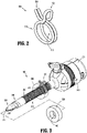
FIG. 2 is a perspective view of a first embodiment of a sleeve stop for use with the cannula ofFIG. 1 ; -
FIG. 3 is an assembly view of the trocar assembly ofFIG. 1 , the first embodiment of the sleeve stop ofFIG. 2 , and a stopping block; -
FIG. 4 is a perspective view of the trocar assembly ofFIGS. 1 and3 including the first embodiment of the sleeve stop ofFIGS. 2 and 3 and the stopping block ofFIG. 3 engaged with tissue; -
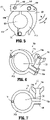
FIG. 5 is a top view of a second embodiment of a sleeve stop; -
FIG. 6 is a perspective view of a third embodiment of a sleeve stop; -
FIG. 7 is a side view of the third embodiment of the sleeve stop ofFIG. 6 ; -
FIGS. 8 and 9 are side views of a fourth embodiment of a sleeve stop; and -
FIGS. 10 and 11 are perspective views of a fifth embodiment of a sleeve stop. - Embodiments of the presently disclosed surgical access device and sleeve stops are described in detail with reference to the drawings, wherein like reference numerals designate corresponding elements in each of the several views.
- As used herein, the term "distal" refers to that portion of the instrument, or component thereof which is farther from the user while the term "proximal" refers to that portion of the instrument or component thereof which is closer to the user.
- Various embodiments of a surgical access device are described herein. Generally, the surgical access device includes a trocar assembly which may be employed during surgery (e.g., laparoscopic surgery) and may, in various embodiments, provide for the sealed access of laparoscopic surgical instruments into an insufflated body cavity, such as the abdominal cavity. As will be described in additional detail below, the trocar assemblies of the present disclosure include a cannula and an obturator insertable therethrough. The cannula and obturator are separate components but are capable of being selectively connected together. For example, the obturator may be inserted into and through the cannula until the handle of the obturator engages, e.g., selectively locks into, a proximal housing of the cannula. In this initial position, the trocar assembly is employed to tunnel through an anatomical structure, e.g., the abdominal wall, either by making a new passage through the structure or by passing through an existing opening through the structure. Once the trocar assembly has tunneled through the anatomical structure, the obturator is removed, leaving the cannula in place in the structure, e.g., in the incision created by the trocar assembly. The proximal housing of the cannula may include seals or valves that prevent the escape of insufflation gases from the body cavity, while also allowing surgical instruments to be inserted into the body cavity. Further details of a surgical access device including a cannula and an obturator are described in
U.S. Patent No. 10,022,149 to Holsten et al., issued on July 17, 2018 U.S. Patent Application Publication No. 2018/0085145 to Okoniewski et al., filed on November 13, 2017 , the entire content of each of which being incorporated by reference herein. - With initial reference to
FIG. 1 , asurgical access device 100 is shown.Surgical access device 100 includes acannula 200, and anobturator 300. Theobturator 300 is insertable through achannel 210 defined by anelongated portion 220 ofcannula 200. Additionally,obturator 300 is selectively engageable with or attachable tocannula 200. More particularly, aproximal portion 302 ofobturator 300 is selectively engageable with or attachable to a proximal portion orhousing 202 ofcannula 200. In use, whenobturator 300 is engaged withcannula 200, adistal end 310 ofobturator 300 is advanced into tissue "T" to create or enlarge an incision or opening in tissue "T" (FIG. 4 ). Alternatively, adistal end 230 ofcannula 200 can be used to create or enlarge an opening in tissue "T," without the use of an obturator, for instance. In either situation, it may be important to limit or control the insertion depth ofcannula 200 with respect to the tissue "T" to help provide optimal access to the target tissue, and to minimize accidental contact between portions ofcannula 200 orobturator 300 with tissue located distally of the target tissue. The present disclosure includes various embodiments of sleeve stops that are positionable oncannula 200, and which are configured to limit thedistance cannula 200 can be advanced with respect to the tissue "T." - With particular reference to
FIGS. 2-4 , a first embodiment of a sleeve stop is shown and is indicated byreference character 500.Sleeve stop 500 is a spring-loaded clamp, and includes aring portion 510, and twoextensions Ring portion 510 defines anaperture 512 therethrough which is sized to engage an outer circumference ofelongated portion 220 ofcannula 200.Extensions ring portion 510. In embodiments,ring portion 510 andextensions sleeve stop 500 may be formed of a single wire formed into the illustrated shape or a similar shape. - When
extensions aperture 512 changes from a first, smaller diameter to a second, larger diameter.Extensions aperture 512 towards its first, smaller diameter. - In its initial, biased position,
aperture 512, defined byring portion 510 ofsleeve stop 500, is configured to fixedly or non-slidingly engageelongated portion 220 ofcannula 200. In its second, non-biased position,aperture 512 is at least slightly larger than an outer diameter ofelongated portion 220 ofcannula 200 thereby enablingsleeve stop 500 to be repositioned alongelongated portion 220 ofcannula 200.. - Additionally, as shown in
FIGS. 3 and4 , a stoppingblock 550 is also positionable onelongated portion 220 ofcannula 200, and distal ofsleeve stop 500. Stoppingblock 550 is configured to contact tissue, and is configured to prevent sleeve stop 500 from contacting tissue, for example. Stoppingblock 550 includes anaperture 560 having a larger diameter than an outer diameter ofelongated portion 220 ofcannula 200, thereby allowing stoppingblock 550 to slidingly engageelongated portion 220 ofcannula 200. - In use, a user moves
extensions sleeve stop 500 toward each other to enlargeaperture 512, slidessleeve stop 500 to a desired position alongelongated portion 220 ofcannula 200, and releasesextensions aperture 512 such thatsleeve stop 500 is fixedly or non-slidingly positioned onelongated portion 220 ofcannula 200. With particular reference toFIGS. 3 and4 , whendistal end 230 of cannula 200 (and/or obturator 300) is inserted into tissue "T," adistal face 552 of stoppingblock 550 contacts the tissue "T," and adistal face 501 of sleeve stop 500 contacts a proximal face (not visible inFIGS. 3 or4 ) of stoppingblock 550. This engagement between the tissue "T" and stoppingblock 550, and between stoppingblock 500 andsleeve stop 500 helps prevent further insertion ofcannula 200 with respect to the tissue "T." Following the surgical procedure, for instance,sleeve stop 500 and/or stoppingblock 550 can be removed fromcannula 200, sterilized, and re-used. - Referring now to
FIG. 5 , a second embodiment of a sleeve stop is shown and is indicated byreference character 600.Sleeve stop 600 is configured to engageelongated portion 220 ofcannula 200, and is usable with stoppingblock 550, as discussed above.Sleeve stop 600 includes abody portion 610 defining anaperture 620, alever 630, and alink 640 interconnectingbody portion 610 andlever 630.Body portion 610 includes afirst section 610a that is pivotably connected to asecond section 610b with afirst pivot 612. Together,first section 610a andsecond section 610b defineaperture 620 therebetween, which is sized to engage an outer circumference ofelongated portion 220 ofcannula 200. -
Link 640 includes aslot 642 configured to slidingly engage apin 614 ofsecond section 610b ofbody portion 610.Link 640 is pivotably engaged withlever 630 by asecond pivot 635.Lever 630 is pivotable aboutsecond pivot 635 in the general direction of arrow "A" inFIG. 5 when transitioning from a first position (shown) to a second position (not shown), and in the general direction of arrow "B" inFIG. 5 when transitioning from the second position to the first position. Aslever 630 pivots, link 640 slides relative tosecond section 610b of body portion 610 (i.e., pin 614 ofsecond section 610b slides withinslot 642 of link 640), such that the diameter defined byaperture 620 changes. Whenlever 630 is in its first position (shown), the diameter defined byaperture 620 is relatively small such thatsleeve stop 600 is configured to fixedly or non-slidingly engageelongated portion 220 ofcannula 200. Whenlever 640 is in its second position, the diameter defined byaperture 620 is relatively large (i.e., larger than an outer diameter ofelongated portion 220 of cannula 200) such thatsleeve stop 600 is configured to be repositioned alongelongated portion 220 ofcannula 200. - In use, a user moves
lever 630 ofsleeve stop 600 in the general direction of arrow "A" away fromfirst section 610a ofbody portion 610 thereby enlargingaperture 620, slides or repositions sleeve stop 600 to a desired position alongelongated portion 220 ofcannula 200, and moveslever 630 in the general direction of arrow "B" towardfirst section 610a ofbody portion 610 to decrease the size ofaperture 620 such thatsleeve stop 600 is fixedly or non-slidingly positioned onelongated portion 220 ofcannula 200.Sleeve stop 600 is also usable with stoppingblock 550 in a similar manner as shown herein and described above with regard to sleeve stop 500. Accordingly, the use ofsleeve stop 600 helps prevent further insertion ofcannula 200 with respect to the tissue "T." Following the surgical procedure, for instance,sleeve stop 600 and/or stoppingblock 550 can be removed fromcannula 200, sterilized, and re-used. - Referring now to
FIGS. 6 and 7 , a third embodiment of a sleeve stop is shown and is indicated byreference character 700.Sleeve stop 700 is configured to engageelongated portion 220 ofcannula 200, and is usable with stoppingblock 550, as discussed above.Sleeve stop 700 includes abody portion 710 having afirst section 710a and asecond section 710b, which are pivotable with respect to each other aboutpivot 711, and which together define anaperture 720 that is sized to engage an outer circumference ofelongated portion 220 ofcannula 200.Sleeve stop 700 also includes an adjustable member 730 (e.g., a wing nut) rotatably engageable withfirst section 710a andsecond section 710b ofbody portion 710. -
Adjustable member 730 includes a threaded portion (hidden from view in the figures), which is configured to engage corresponding threaded sections ofrespective extensions first section 710a andsecond section 710b ofbody portion 710. Asadjustable member 730 is rotated in a first direction (e.g., clockwise) relative tobody portion 710,extension 712a offirst section 710a moves towardextension 712b ofsecond section 710b (about pivot 711), thereby reducing the size ofaperture 720 such that sleeve stop 700 fixedly or non-slidingly engageselongated portion 220 ofcannula 200 and is unable to slide relative thereto. Asadjustable member 730 is rotated in a second direction (e.g., counter-clockwise) relative tobody portion 710,extension 712a offirst section 710a moves away fromextension 712b ofsecond section 710b (about pivot 711), thereby increasing the size ofaperture 720 such thatsleeve stop 700 is repositionable alongelongated portion 220 ofcannula 200. - In use, a user rotates
adjustable member 730 ofsleeve stop 700 in the second direction, for instance, to thereby enlargeaperture 720, slidessleeve stop 700 to a desired position alongelongated portion 220 ofcannula 200, and rotatesadjustable member 730 in the first, opposite direction, for instance, to decrease the size ofaperture 720 such thatsleeve stop 700 is fixedly or non-slidingly positioned onelongated portion 220 ofcannula 200.Sleeve stop 700 is also usable with stoppingblock 550 in a similar manner as shown herein and described above with regard to sleeve stop 500. Accordingly, the use ofsleeve stop 700 helps prevent further insertion ofcannula 200 with respect to the tissue "T." Following the surgical procedure, for instance,sleeve stop 700 and/or stoppingblock 550 can be removed fromcannula 200, sterilized, and re-used. - Referring now to
FIGS. 8-9 , a fourth embodiment of a sleeve stop is shown and is indicated byreference character 800.Sleeve stop 800 is configured to engageelongated portion 220 ofcannula 200, and is usable with stoppingblock 550, as discussed above.Sleeve stop 800 is a unitary structure and includes abody portion 810 having afirst section 810a and asecond section 810b interconnected by aliving hinge 820. It is envisioned that an entirety ofsleeve stop 800 is made from a single material, e.g., plastic. Together,first section 810a andsecond section 810b define anaperture 812.First section 810a ofbody portion 810 includes afinger 830 having a plurality ofteeth 832.Second section 810b ofbody portion 810 includes areceptacle 840 having a plurality ofteeth 842 for slidingly receivingfinger 830. - Engagement between plurality of
teeth 832 offinger 830 and plurality ofteeth 842 of receptacle helps maintain a desired portion offinger 830 withinreceptacle 840, which corresponds to a desired size ofaperture 812. Whenaperture 812 is larger than an outer diameter ofelongated portion 220 of cannula 200 (e.g.,FIG. 8 ),sleeve stop 800 is able to be repositionable alongelongated portion 220 ofcannula 200. Whenaperture 812 is equal to or smaller than the outer diameter ofelongated portion 220 of cannula 200 (e.g.,FIG. 9 ), sleeve stop 800 fixedly engageselongated portion 220 ofcannula 200 and is unable to slide relative thereto. - In use, a user is able to position sleeve stop 800 around
elongated portion 220 ofcannula 200 whensleeve stop 800 is in an open position (FIG. 8 ),slide sleeve stop 800 to a desired position alongelongated portion 220 ofcannula 200, and insert at least a portion offinger 830 intoreceptacle 840 to decrease the size ofaperture 812 and to maintain the position offirst section 810a ofbody portion 810 relative tosecond section 810b of body portion 810 (FIG. 9 ) such thatsleeve stop 800 is fixedly or non-slidingly positioned onelongated portion 220 ofcannula 200.Sleeve stop 800 is also usable with stoppingblock 550 in a similar manner as shown herein and described above with regard to sleeve stop 500. Accordingly, the use ofsleeve stop 800 helps prevent further insertion ofcannula 200 with respect to the tissue. Following the surgical procedure, for instance,sleeve stop 800 and/or stoppingblock 550 can be removed fromcannula 200, sterilized, and re-used. - Referring now to
FIGS. 10-11 , a fifth embodiment of a sleeve stop is shown and is indicated byreference character 900.Sleeve stop 900 is configured to engageelongated portion 220 ofcannula 200, and is usable with stoppingblock 550, as discussed above.Sleeve stop 900 includes abody portion 910 having afirst section 910a and asecond section 910b interconnected by aliving hinge 920. Together,first section 910a andsecond section 910b define anaperture 912.First section 910a ofbody portion 910 includes afinger 930 having alip 932.Second section 910b ofbody portion 910 includes areceptacle 940 for receivinglip 932 offinger 930. - Engagement between
lip 932 offinger 930 andreceptacle 940 helps maintainfirst section 910a andsecond section 910b ofbody portion 910 in a closed position (FIG. 11 ), which corresponds to a desired size ofaperture 912. Whenfirst section 910a andsecond section 910b ofbody portion 910 are in an open position (FIG. 10 ),aperture 912 is larger than an outer diameter ofelongated portion 220 ofcannula 200 such thatsleeve stop 900 is able to be repositionable alongelongated portion 220 ofcannula 200. Whenfirst section 910a andsecond section 910b ofbody portion 910 are a closed position (FIG. 11 ),aperture 912 is equal to or smaller than the outer diameter ofelongated portion 220 ofcannula 200 such that sleeve stop 900 fixedly engageselongated portion 220 ofcannula 200 and is unable to slide relative thereto. - In use, a user is able to position sleeve stop 900 around
elongated portion 220 ofcannula 200 whensleeve stop 900 is in an open position (FIG. 10 ),slide sleeve stop 900 to a desired position alongelongated portion 220 ofcannula 200, and insertlip 932 offinger 930 intoreceptacle 940 to decrease the size ofaperture 912 and to maintain the position offirst section 910a ofbody portion 910 relative tosecond section 910b of body portion 910 (FIG. 11 ) such thatsleeve stop 900 is fixedly or non-slidingly positioned onelongated portion 220 ofcannula 200.Sleeve stop 900 is also usable with stoppingblock 550 in a similar manner as shown herein and described above with regard to sleeve stop 500. Accordingly, the use ofsleeve stop 900 helps prevent further insertion ofcannula 200 with respect to the tissue. Following the surgical procedure, for instance,sleeve stop 900 and/or stoppingblock 550 can be removed fromcannula 200, sterilized, and re-used. - While the above description contains many specifics, these specifics should not be construed as limitations on the scope of the present disclosure, but merely as illustrations of various embodiments thereof. Therefore, the above description should not be construed as limiting, but merely as exemplifications of various embodiments. Those skilled in the art will envision other modifications within the scope and spirit of the claims appended hereto.
- The invention may be described by reference to the following numbered paragraphs:
- 1. A surgical access device comprising: a cannula having a housing and an elongated portion extending distally from the housing, the elongated portion defining a channel extending therethrough, a distal portion of the elongated portion configured for engaging tissue; and a sleeve stop configured for selective engagement with the elongated portion of the cannula, and configured to limit distal advancement of the cannula with respect to tissue, the sleeve stop being a unitary structure and including a body portion having a first section and a second section, the first section and the second section are interconnected by a living hinge, wherein the first section is configured to selectively engage the second section.
- 2. The surgical access device according to
paragraph 1, wherein the first section of the body portion of the sleeve stop includes a finger, and wherein the second section of the body portion of the sleeve stop includes a receptacle configured for slidingly receiving the finger. - 3. The surgical access device according to paragraph 2, wherein the finger includes a plurality of teeth.
- 4. The surgical access device according to paragraph 3, wherein the receptacle includes a plurality of teeth.
- 5. The surgical access device according to paragraph 4, wherein engagement between the plurality of teeth of the finger and the plurality of teeth of the receptacle helps maintain a size of an aperture defined between the first section of the body portion of the sleeve stop and the second portion of the body portion of the sleeve stop.
- 6. The surgical access device according to
paragraph 1, wherein engagement between the first section of the body portion of the sleeve stop and the second portion of the body portion of the sleeve stop defines an aperture therebetween. - 7. The surgical access device according to
paragraph 1, wherein the sleeve stop is made from a single material. - 8. The surgical access device according to paragraph 7, wherein the sleeve stop is made from plastic.
- 9. The surgical access device according to
paragraph 1, further including a stopping block positionable on the elongated portion of the cannula and distally of the sleeve stop, the stopping block configured to contact tissue and to prevent the sleeve stop from contacting tissue. - 10. A surgical access device comprising: a cannula having a housing and an elongated portion extending distally from the housing, the elongated portion defining a channel extending therethrough, a distal portion of the elongated portion configured for engaging tissue; and a sleeve stop configured for selective engagement with the elongated portion of the cannula, and configured to limit distal advancement of the cannula with respect to tissue, the sleeve stop including an adjustable member and a body portion having a first section and a second section, the first section being pivotable relative to the second section about a pivot, the first section and the second section defining an aperture therebetween for slidable reception of the cannula, the adjustable member configured to threadably engage a threaded aperture of the first section of the sleeve stop and a threaded aperture of the second section of the sleeve stop.
- 11. The surgical access device according to paragraph 10, wherein rotation of the adjustable member in a first direction relative to the first section of the sleeve stop causes a diameter of the aperture to increase, and wherein rotation of the adjustable member in a second direction relative to the first section of the sleeve stop causes the diameter of the aperture to decrease.
- 12. The surgical access device according to paragraph 10, wherein the adjustable member includes a wing nut.
- 13. The surgical access device according to paragraph 10, wherein the first section of the sleeve stop includes a semi-circular portion and an extension portion, and wherein the second section of the sleeve stop includes a semi-circular portion and an extension portion.
- 14. The surgical access device according to paragraph 13, wherein the threaded aperture of the first section of the sleeve stop is on the extension of the first section, and wherein the threaded aperture of the second section of the sleeve stop is on the extension of the second section.
- 15. The surgical access device according to paragraph 10, further including a stopping block positionable on the elongated portion of the cannula and distally of the sleeve stop, the stopping block configured to contact tissue and to prevent the sleeve stop from contacting tissue.
Claims (12)
- A sleeve stop for use with a surgical access device, the sleeve stop comprising:a body portion having a first section and a second section, the first section including a threaded aperture, the second section including a threaded aperture, the first section being pivotable relative to the second section about a pivot, the first section and the second section defining an aperture therebetween for slidable reception of a cannula; andan adjustable member disposed in mechanical cooperation with the threaded aperture of the first section and with the threaded aperture of the second section, wherein rotation of the adjustable member relative to the first section causes a diameter of the aperture to change.
- The sleeve stop according to claim 1, wherein rotation of the adjustable member in a first direction relative to the first section of the sleeve stop causes the diameter of the aperture to increase.
- The sleeve stop according to claim 2, wherein rotation of the adjustable member in a second direction relative to the first section of the sleeve stop causes the diameter of the aperture to decrease.
- The sleeve stop according to any preceding claim, wherein the adjustable member includes a wing nut.
- The sleeve stop according to any preceding claim, wherein the first section of the body portion includes a semi-circular portion and an extension portion, and the second section of the body portion includes a semi-circular portion and an extension portion.
- The sleeve stop according to claim 5, wherein the threaded aperture of the first section is formed within the extension of the first section.
- The sleeve stop according to claim 6, wherein the threaded aperture of the second section is formed within the extension of the second section.
- The sleeve stop according to any preceding claim, wherein engagement between the adjustable member, the first section, and the second section helps maintain a size of the aperture defined between the first section and the second section.
- The sleeve stop according to any preceding claim, wherein an entirety of the adjustable member is rotatable relative to the first section of the body portion.
- The sleeve stop according to claim 9, wherein the entirety of the adjustable member is rotatable relative to the second section of the body portion.
- The sleeve stop according to any preceding claim, wherein the pivot extends through the first section of the body portion.
- The sleeve stop according to claim 11, wherein the pivot extends through the second section of the body portion.
Applications Claiming Priority (2)
| Application Number | Priority Date | Filing Date | Title |
|---|---|---|---|
| US16/237,788 US20200205855A1 (en) | 2019-01-02 | 2019-01-02 | Surgical access device and sleeve stops for use therewith |
| EP19218663.3A EP3677202A1 (en) | 2019-01-02 | 2019-12-20 | Surgical access device and sleeve stops for use therewith |
Related Parent Applications (1)
| Application Number | Title | Priority Date | Filing Date |
|---|---|---|---|
| EP19218663.3A Division EP3677202A1 (en) | 2019-01-02 | 2019-12-20 | Surgical access device and sleeve stops for use therewith |
Publications (2)
| Publication Number | Publication Date |
|---|---|
| EP3998028A1 true EP3998028A1 (en) | 2022-05-18 |
| EP3998028B1 EP3998028B1 (en) | 2024-06-26 |
Family
ID=69411149
Family Applications (2)
| Application Number | Title | Priority Date | Filing Date |
|---|---|---|---|
| EP19218663.3A Withdrawn EP3677202A1 (en) | 2019-01-02 | 2019-12-20 | Surgical access device and sleeve stops for use therewith |
| EP21215640.0A Active EP3998028B1 (en) | 2019-01-02 | 2019-12-20 | Surgical access device and sleeve stops for use therewith |
Family Applications Before (1)
| Application Number | Title | Priority Date | Filing Date |
|---|---|---|---|
| EP19218663.3A Withdrawn EP3677202A1 (en) | 2019-01-02 | 2019-12-20 | Surgical access device and sleeve stops for use therewith |
Country Status (5)
| Country | Link |
|---|---|
| US (2) | US20200205855A1 (en) |
| EP (2) | EP3677202A1 (en) |
| JP (1) | JP2020108739A (en) |
| AU (1) | AU2019271936A1 (en) |
| CA (1) | CA3063882A1 (en) |
Families Citing this family (7)
| Publication number | Priority date | Publication date | Assignee | Title |
|---|---|---|---|---|
| KR102689313B1 (en) | 2019-03-26 | 2024-07-30 | 콘메드 코포레이션 | Gas circulation system with gas-sealed access cap and valve-sealed access cap for robotic-assisted surgical procedures |
| USD1018848S1 (en) * | 2019-11-04 | 2024-03-19 | Cilag Gmbh International | Trocar |
| US11633211B2 (en) | 2020-05-01 | 2023-04-25 | Cilag Gmbh International | Pinch to release cannula depth limiter |
| US12213699B2 (en) * | 2020-05-01 | 2025-02-04 | Cilag Gmbh International | Threaded cannula depth limiter |
| US11980392B2 (en) | 2020-05-01 | 2024-05-14 | Cilag Gmbh International | Pinch-to-clamp cannula depth limiter |
| US11986215B2 (en) | 2020-05-01 | 2024-05-21 | Cilag Gmbh International | Universal size multi-walled elastomer cannula depth limiter |
| US12402912B2 (en) | 2020-05-01 | 2025-09-02 | Cilag Gmbh International | Multi-diameter cannula depth limiter |
Citations (6)
| Publication number | Priority date | Publication date | Assignee | Title |
|---|---|---|---|---|
| US5713869A (en) * | 1995-03-08 | 1998-02-03 | Morejon; Orlando | Trocar assembly |
| US5716369A (en) * | 1994-03-25 | 1998-02-10 | Riza; Erol D. | Apparatus facilitating suturing in laparoscopic surgery |
| DE102005047527A1 (en) * | 2005-10-04 | 2007-04-05 | Rheinisch-Westfälisch Technische Hochschule Aachen | Trocar sleeve retaining device for minimal invasive surgery such as laproscopy, has retaining arms whose one end is arranged on retainer and another end is supported at surgery region such as skin of patient |
| US20180085145A1 (en) | 2015-05-15 | 2018-03-29 | Covidien Lp | Surgical access device |
| WO2018094478A1 (en) * | 2016-11-28 | 2018-05-31 | Inova Medical Pty Ltd | Percutaneous drainage device |
| US10022149B2 (en) | 2012-09-28 | 2018-07-17 | Covidien Lp | Optical trocar visualization system and apparatus |
Family Cites Families (15)
| Publication number | Priority date | Publication date | Assignee | Title |
|---|---|---|---|---|
| US2876027A (en) * | 1957-02-26 | 1959-03-03 | William B Sulmonetti | Locking swivel type clamp assembly |
| US5147316A (en) * | 1990-11-19 | 1992-09-15 | Castillenti Thomas A | Laparoscopic trocar with self-locking port sleeve |
| US5267970A (en) * | 1991-11-01 | 1993-12-07 | Origin Medsystems, Inc. | Device for anchoring trocar sleeve |
| US5551421A (en) * | 1992-04-01 | 1996-09-03 | Noureldin; Abdel H. | Device for securement of an endotracheal tube in a patient's mouth |
| US5364367A (en) * | 1993-04-30 | 1994-11-15 | Minnesota Mining And Manufacturing Company | Cannula anchor |
| JPH0874814A (en) * | 1994-09-06 | 1996-03-19 | Daiwa Kasei Kogyo Kk | Clamp |
| US20020109057A1 (en) * | 1998-11-09 | 2002-08-15 | Wooten Donald W. | Adjustable weapon auxiliary mount |
| US20040138702A1 (en) * | 2001-05-31 | 2004-07-15 | Kenneth Peartree | Balloon cannula with over-center clamp |
| JP3087166U (en) * | 2002-01-08 | 2002-07-19 | 呉春▲りょう▼ | Quick-release bar body fasteners |
| JP2004201741A (en) * | 2002-12-24 | 2004-07-22 | Terumo Corp | Blood pressure cuff |
| US7691089B2 (en) * | 2005-06-21 | 2010-04-06 | Tyco Healthcare Group Lp | Adjustable trocar washer |
| US7507210B2 (en) * | 2006-05-01 | 2009-03-24 | Ethicon Endo-Surgery, Inc. | Biopsy cannula adjustable depth stop |
| AU2007283152A1 (en) * | 2006-08-10 | 2008-02-14 | Unomedical A/S | A fixation device for holding a medical instrument |
| US20100286478A1 (en) * | 2009-04-23 | 2010-11-11 | Usgi Medical, Inc. | Flexible surgery access systems |
| JP2014061933A (en) * | 2012-09-24 | 2014-04-10 | Sumitomo Wiring Syst Ltd | Binding band |
-
2019
- 2019-01-02 US US16/237,788 patent/US20200205855A1/en not_active Abandoned
- 2019-11-26 AU AU2019271936A patent/AU2019271936A1/en not_active Abandoned
- 2019-12-04 JP JP2019219457A patent/JP2020108739A/en active Pending
- 2019-12-05 CA CA3063882A patent/CA3063882A1/en active Pending
- 2019-12-20 EP EP19218663.3A patent/EP3677202A1/en not_active Withdrawn
- 2019-12-20 EP EP21215640.0A patent/EP3998028B1/en active Active
-
2021
- 2021-02-08 US US17/169,934 patent/US20210161557A1/en not_active Abandoned
Patent Citations (6)
| Publication number | Priority date | Publication date | Assignee | Title |
|---|---|---|---|---|
| US5716369A (en) * | 1994-03-25 | 1998-02-10 | Riza; Erol D. | Apparatus facilitating suturing in laparoscopic surgery |
| US5713869A (en) * | 1995-03-08 | 1998-02-03 | Morejon; Orlando | Trocar assembly |
| DE102005047527A1 (en) * | 2005-10-04 | 2007-04-05 | Rheinisch-Westfälisch Technische Hochschule Aachen | Trocar sleeve retaining device for minimal invasive surgery such as laproscopy, has retaining arms whose one end is arranged on retainer and another end is supported at surgery region such as skin of patient |
| US10022149B2 (en) | 2012-09-28 | 2018-07-17 | Covidien Lp | Optical trocar visualization system and apparatus |
| US20180085145A1 (en) | 2015-05-15 | 2018-03-29 | Covidien Lp | Surgical access device |
| WO2018094478A1 (en) * | 2016-11-28 | 2018-05-31 | Inova Medical Pty Ltd | Percutaneous drainage device |
Also Published As
| Publication number | Publication date |
|---|---|
| US20210161557A1 (en) | 2021-06-03 |
| EP3677202A1 (en) | 2020-07-08 |
| EP3998028B1 (en) | 2024-06-26 |
| JP2020108739A (en) | 2020-07-16 |
| US20200205855A1 (en) | 2020-07-02 |
| CA3063882A1 (en) | 2020-07-02 |
| AU2019271936A1 (en) | 2020-07-16 |
Similar Documents
| Publication | Publication Date | Title |
|---|---|---|
| EP3998028B1 (en) | Surgical access device and sleeve stops for use therewith | |
| US9017250B2 (en) | Seal anchor with non-parallel lumens | |
| US9226770B2 (en) | Optical penetrating adapter for surgical portal | |
| US20150327848A1 (en) | Integral foam port | |
| JP2011218174A (en) | Bariatric foam port | |
| EP2353527A2 (en) | Port fixation with varying thread diameter | |
| JP5377336B2 (en) | Surgical visual access device | |
| US20210228198A1 (en) | Surgical access device with adjustable length | |
| EP1889580A2 (en) | Surgical seal assembly | |
| EP4070745A1 (en) | Surgical access device including an anchor having a suture retention mechanism | |
| EP2233093A1 (en) | Seal device with adjustable aperture | |
| US11457949B2 (en) | Surgical access device and seal guard for use therewith | |
| EP1738701A1 (en) | Beveled access apparatus with locking ribs elements | |
| US12419665B2 (en) | Surgical access device with rotatably actuated fixation mechanism | |
| US11864752B2 (en) | Endoscopic stitching device for supporting suture needles in various orientations |
Legal Events
| Date | Code | Title | Description |
|---|---|---|---|
| PUAI | Public reference made under article 153(3) epc to a published international application that has entered the european phase |
Free format text: ORIGINAL CODE: 0009012 |
|
| STAA | Information on the status of an ep patent application or granted ep patent |
Free format text: STATUS: THE APPLICATION HAS BEEN PUBLISHED |
|
| AC | Divisional application: reference to earlier application |
Ref document number: 3677202 Country of ref document: EP Kind code of ref document: P |
|
| AK | Designated contracting states |
Kind code of ref document: A1 Designated state(s): AL AT BE BG CH CY CZ DE DK EE ES FI FR GB GR HR HU IE IS IT LI LT LU LV MC MK MT NL NO PL PT RO RS SE SI SK SM TR |
|
| STAA | Information on the status of an ep patent application or granted ep patent |
Free format text: STATUS: REQUEST FOR EXAMINATION WAS MADE |
|
| 17P | Request for examination filed |
Effective date: 20221107 |
|
| RBV | Designated contracting states (corrected) |
Designated state(s): AL AT BE BG CH CY CZ DE DK EE ES FI FR GB GR HR HU IE IS IT LI LT LU LV MC MK MT NL NO PL PT RO RS SE SI SK SM TR |
|
| STAA | Information on the status of an ep patent application or granted ep patent |
Free format text: STATUS: EXAMINATION IS IN PROGRESS |
|
| 17Q | First examination report despatched |
Effective date: 20231030 |
|
| GRAP | Despatch of communication of intention to grant a patent |
Free format text: ORIGINAL CODE: EPIDOSNIGR1 |
|
| STAA | Information on the status of an ep patent application or granted ep patent |
Free format text: STATUS: GRANT OF PATENT IS INTENDED |
|
| INTG | Intention to grant announced |
Effective date: 20240219 |
|
| GRAS | Grant fee paid |
Free format text: ORIGINAL CODE: EPIDOSNIGR3 |
|
| GRAA | (expected) grant |
Free format text: ORIGINAL CODE: 0009210 |
|
| STAA | Information on the status of an ep patent application or granted ep patent |
Free format text: STATUS: THE PATENT HAS BEEN GRANTED |
|
| AC | Divisional application: reference to earlier application |
Ref document number: 3677202 Country of ref document: EP Kind code of ref document: P |
|
| AK | Designated contracting states |
Kind code of ref document: B1 Designated state(s): AL AT BE BG CH CY CZ DE DK EE ES FI FR GB GR HR HU IE IS IT LI LT LU LV MC MK MT NL NO PL PT RO RS SE SI SK SM TR |
|
| REG | Reference to a national code |
Ref country code: GB Ref legal event code: FG4D |
|
| REG | Reference to a national code |
Ref country code: CH Ref legal event code: EP |
|
| REG | Reference to a national code |
Ref country code: DE Ref legal event code: R096 Ref document number: 602019054433 Country of ref document: DE |
|
| PG25 | Lapsed in a contracting state [announced via postgrant information from national office to epo] |
Ref country code: BG Free format text: LAPSE BECAUSE OF FAILURE TO SUBMIT A TRANSLATION OF THE DESCRIPTION OR TO PAY THE FEE WITHIN THE PRESCRIBED TIME-LIMIT Effective date: 20240626 |
|
| PG25 | Lapsed in a contracting state [announced via postgrant information from national office to epo] |
Ref country code: FI Free format text: LAPSE BECAUSE OF FAILURE TO SUBMIT A TRANSLATION OF THE DESCRIPTION OR TO PAY THE FEE WITHIN THE PRESCRIBED TIME-LIMIT Effective date: 20240626 Ref country code: HR Free format text: LAPSE BECAUSE OF FAILURE TO SUBMIT A TRANSLATION OF THE DESCRIPTION OR TO PAY THE FEE WITHIN THE PRESCRIBED TIME-LIMIT Effective date: 20240626 |
|
| REG | Reference to a national code |
Ref country code: LT Ref legal event code: MG9D |
|
| PG25 | Lapsed in a contracting state [announced via postgrant information from national office to epo] |
Ref country code: GR Free format text: LAPSE BECAUSE OF FAILURE TO SUBMIT A TRANSLATION OF THE DESCRIPTION OR TO PAY THE FEE WITHIN THE PRESCRIBED TIME-LIMIT Effective date: 20240927 |
|
| PG25 | Lapsed in a contracting state [announced via postgrant information from national office to epo] |
Ref country code: LV Free format text: LAPSE BECAUSE OF FAILURE TO SUBMIT A TRANSLATION OF THE DESCRIPTION OR TO PAY THE FEE WITHIN THE PRESCRIBED TIME-LIMIT Effective date: 20240626 |
|
| REG | Reference to a national code |
Ref country code: NL Ref legal event code: MP Effective date: 20240626 |
|
| PG25 | Lapsed in a contracting state [announced via postgrant information from national office to epo] |
Ref country code: NO Free format text: LAPSE BECAUSE OF FAILURE TO SUBMIT A TRANSLATION OF THE DESCRIPTION OR TO PAY THE FEE WITHIN THE PRESCRIBED TIME-LIMIT Effective date: 20240926 Ref country code: LV Free format text: LAPSE BECAUSE OF FAILURE TO SUBMIT A TRANSLATION OF THE DESCRIPTION OR TO PAY THE FEE WITHIN THE PRESCRIBED TIME-LIMIT Effective date: 20240626 Ref country code: HR Free format text: LAPSE BECAUSE OF FAILURE TO SUBMIT A TRANSLATION OF THE DESCRIPTION OR TO PAY THE FEE WITHIN THE PRESCRIBED TIME-LIMIT Effective date: 20240626 Ref country code: GR Free format text: LAPSE BECAUSE OF FAILURE TO SUBMIT A TRANSLATION OF THE DESCRIPTION OR TO PAY THE FEE WITHIN THE PRESCRIBED TIME-LIMIT Effective date: 20240927 Ref country code: FI Free format text: LAPSE BECAUSE OF FAILURE TO SUBMIT A TRANSLATION OF THE DESCRIPTION OR TO PAY THE FEE WITHIN THE PRESCRIBED TIME-LIMIT Effective date: 20240626 Ref country code: BG Free format text: LAPSE BECAUSE OF FAILURE TO SUBMIT A TRANSLATION OF THE DESCRIPTION OR TO PAY THE FEE WITHIN THE PRESCRIBED TIME-LIMIT Effective date: 20240626 Ref country code: RS Free format text: LAPSE BECAUSE OF FAILURE TO SUBMIT A TRANSLATION OF THE DESCRIPTION OR TO PAY THE FEE WITHIN THE PRESCRIBED TIME-LIMIT Effective date: 20240926 |
|
| PG25 | Lapsed in a contracting state [announced via postgrant information from national office to epo] |
Ref country code: NL Free format text: LAPSE BECAUSE OF FAILURE TO SUBMIT A TRANSLATION OF THE DESCRIPTION OR TO PAY THE FEE WITHIN THE PRESCRIBED TIME-LIMIT Effective date: 20240626 |
|
| REG | Reference to a national code |
Ref country code: AT Ref legal event code: MK05 Ref document number: 1697040 Country of ref document: AT Kind code of ref document: T Effective date: 20240626 |
|
| PG25 | Lapsed in a contracting state [announced via postgrant information from national office to epo] |
Ref country code: NL Free format text: LAPSE BECAUSE OF FAILURE TO SUBMIT A TRANSLATION OF THE DESCRIPTION OR TO PAY THE FEE WITHIN THE PRESCRIBED TIME-LIMIT Effective date: 20240626 |
|
| PG25 | Lapsed in a contracting state [announced via postgrant information from national office to epo] |
Ref country code: PT Free format text: LAPSE BECAUSE OF FAILURE TO SUBMIT A TRANSLATION OF THE DESCRIPTION OR TO PAY THE FEE WITHIN THE PRESCRIBED TIME-LIMIT Effective date: 20241028 |
|
| PG25 | Lapsed in a contracting state [announced via postgrant information from national office to epo] |
Ref country code: PT Free format text: LAPSE BECAUSE OF FAILURE TO SUBMIT A TRANSLATION OF THE DESCRIPTION OR TO PAY THE FEE WITHIN THE PRESCRIBED TIME-LIMIT Effective date: 20241028 |
|
| PG25 | Lapsed in a contracting state [announced via postgrant information from national office to epo] |
Ref country code: PL Free format text: LAPSE BECAUSE OF FAILURE TO SUBMIT A TRANSLATION OF THE DESCRIPTION OR TO PAY THE FEE WITHIN THE PRESCRIBED TIME-LIMIT Effective date: 20240626 |
|
| PG25 | Lapsed in a contracting state [announced via postgrant information from national office to epo] |
Ref country code: EE Free format text: LAPSE BECAUSE OF FAILURE TO SUBMIT A TRANSLATION OF THE DESCRIPTION OR TO PAY THE FEE WITHIN THE PRESCRIBED TIME-LIMIT Effective date: 20240626 |
|
| PG25 | Lapsed in a contracting state [announced via postgrant information from national office to epo] |
Ref country code: AT Free format text: LAPSE BECAUSE OF FAILURE TO SUBMIT A TRANSLATION OF THE DESCRIPTION OR TO PAY THE FEE WITHIN THE PRESCRIBED TIME-LIMIT Effective date: 20240626 Ref country code: IS Free format text: LAPSE BECAUSE OF FAILURE TO SUBMIT A TRANSLATION OF THE DESCRIPTION OR TO PAY THE FEE WITHIN THE PRESCRIBED TIME-LIMIT Effective date: 20241026 |
|
| PG25 | Lapsed in a contracting state [announced via postgrant information from national office to epo] |
Ref country code: CZ Free format text: LAPSE BECAUSE OF FAILURE TO SUBMIT A TRANSLATION OF THE DESCRIPTION OR TO PAY THE FEE WITHIN THE PRESCRIBED TIME-LIMIT Effective date: 20240626 |
|
| PG25 | Lapsed in a contracting state [announced via postgrant information from national office to epo] |
Ref country code: SK Free format text: LAPSE BECAUSE OF FAILURE TO SUBMIT A TRANSLATION OF THE DESCRIPTION OR TO PAY THE FEE WITHIN THE PRESCRIBED TIME-LIMIT Effective date: 20240626 Ref country code: RO Free format text: LAPSE BECAUSE OF FAILURE TO SUBMIT A TRANSLATION OF THE DESCRIPTION OR TO PAY THE FEE WITHIN THE PRESCRIBED TIME-LIMIT Effective date: 20240626 |
|
| PG25 | Lapsed in a contracting state [announced via postgrant information from national office to epo] |
Ref country code: ES Free format text: LAPSE BECAUSE OF FAILURE TO SUBMIT A TRANSLATION OF THE DESCRIPTION OR TO PAY THE FEE WITHIN THE PRESCRIBED TIME-LIMIT Effective date: 20240626 Ref country code: SM Free format text: LAPSE BECAUSE OF FAILURE TO SUBMIT A TRANSLATION OF THE DESCRIPTION OR TO PAY THE FEE WITHIN THE PRESCRIBED TIME-LIMIT Effective date: 20240626 |
|
| PG25 | Lapsed in a contracting state [announced via postgrant information from national office to epo] |
Ref country code: SM Free format text: LAPSE BECAUSE OF FAILURE TO SUBMIT A TRANSLATION OF THE DESCRIPTION OR TO PAY THE FEE WITHIN THE PRESCRIBED TIME-LIMIT Effective date: 20240626 Ref country code: SK Free format text: LAPSE BECAUSE OF FAILURE TO SUBMIT A TRANSLATION OF THE DESCRIPTION OR TO PAY THE FEE WITHIN THE PRESCRIBED TIME-LIMIT Effective date: 20240626 Ref country code: RO Free format text: LAPSE BECAUSE OF FAILURE TO SUBMIT A TRANSLATION OF THE DESCRIPTION OR TO PAY THE FEE WITHIN THE PRESCRIBED TIME-LIMIT Effective date: 20240626 Ref country code: PL Free format text: LAPSE BECAUSE OF FAILURE TO SUBMIT A TRANSLATION OF THE DESCRIPTION OR TO PAY THE FEE WITHIN THE PRESCRIBED TIME-LIMIT Effective date: 20240626 Ref country code: IS Free format text: LAPSE BECAUSE OF FAILURE TO SUBMIT A TRANSLATION OF THE DESCRIPTION OR TO PAY THE FEE WITHIN THE PRESCRIBED TIME-LIMIT Effective date: 20241026 Ref country code: ES Free format text: LAPSE BECAUSE OF FAILURE TO SUBMIT A TRANSLATION OF THE DESCRIPTION OR TO PAY THE FEE WITHIN THE PRESCRIBED TIME-LIMIT Effective date: 20240626 Ref country code: EE Free format text: LAPSE BECAUSE OF FAILURE TO SUBMIT A TRANSLATION OF THE DESCRIPTION OR TO PAY THE FEE WITHIN THE PRESCRIBED TIME-LIMIT Effective date: 20240626 Ref country code: CZ Free format text: LAPSE BECAUSE OF FAILURE TO SUBMIT A TRANSLATION OF THE DESCRIPTION OR TO PAY THE FEE WITHIN THE PRESCRIBED TIME-LIMIT Effective date: 20240626 Ref country code: AT Free format text: LAPSE BECAUSE OF FAILURE TO SUBMIT A TRANSLATION OF THE DESCRIPTION OR TO PAY THE FEE WITHIN THE PRESCRIBED TIME-LIMIT Effective date: 20240626 |
|
| PG25 | Lapsed in a contracting state [announced via postgrant information from national office to epo] |
Ref country code: IT Free format text: LAPSE BECAUSE OF FAILURE TO SUBMIT A TRANSLATION OF THE DESCRIPTION OR TO PAY THE FEE WITHIN THE PRESCRIBED TIME-LIMIT Effective date: 20240626 |
|
| REG | Reference to a national code |
Ref country code: DE Ref legal event code: R097 Ref document number: 602019054433 Country of ref document: DE |
|
| PG25 | Lapsed in a contracting state [announced via postgrant information from national office to epo] |
Ref country code: DK Free format text: LAPSE BECAUSE OF FAILURE TO SUBMIT A TRANSLATION OF THE DESCRIPTION OR TO PAY THE FEE WITHIN THE PRESCRIBED TIME-LIMIT Effective date: 20240626 |
|
| PLBE | No opposition filed within time limit |
Free format text: ORIGINAL CODE: 0009261 |
|
| STAA | Information on the status of an ep patent application or granted ep patent |
Free format text: STATUS: NO OPPOSITION FILED WITHIN TIME LIMIT |
|
| 26N | No opposition filed |
Effective date: 20250327 |
|
| PG25 | Lapsed in a contracting state [announced via postgrant information from national office to epo] |
Ref country code: MC Free format text: LAPSE BECAUSE OF FAILURE TO SUBMIT A TRANSLATION OF THE DESCRIPTION OR TO PAY THE FEE WITHIN THE PRESCRIBED TIME-LIMIT Effective date: 20240626 |
|
| REG | Reference to a national code |
Ref country code: CH Ref legal event code: PL |
|
| PG25 | Lapsed in a contracting state [announced via postgrant information from national office to epo] |
Ref country code: LU Free format text: LAPSE BECAUSE OF NON-PAYMENT OF DUE FEES Effective date: 20241220 |
|
| GBPC | Gb: european patent ceased through non-payment of renewal fee |
Effective date: 20241220 |
|
| PG25 | Lapsed in a contracting state [announced via postgrant information from national office to epo] |
Ref country code: SE Free format text: LAPSE BECAUSE OF FAILURE TO SUBMIT A TRANSLATION OF THE DESCRIPTION OR TO PAY THE FEE WITHIN THE PRESCRIBED TIME-LIMIT Effective date: 20240626 |
|
| REG | Reference to a national code |
Ref country code: BE Ref legal event code: MM Effective date: 20241231 |
|
| PG25 | Lapsed in a contracting state [announced via postgrant information from national office to epo] |
Ref country code: GB Free format text: LAPSE BECAUSE OF NON-PAYMENT OF DUE FEES Effective date: 20241220 Ref country code: BE Free format text: LAPSE BECAUSE OF NON-PAYMENT OF DUE FEES Effective date: 20241231 |
|
| PG25 | Lapsed in a contracting state [announced via postgrant information from national office to epo] |
Ref country code: FR Free format text: LAPSE BECAUSE OF NON-PAYMENT OF DUE FEES Effective date: 20241231 |
|
| PG25 | Lapsed in a contracting state [announced via postgrant information from national office to epo] |
Ref country code: CH Free format text: LAPSE BECAUSE OF NON-PAYMENT OF DUE FEES Effective date: 20241231 |
|
| PG25 | Lapsed in a contracting state [announced via postgrant information from national office to epo] |
Ref country code: IE Free format text: LAPSE BECAUSE OF NON-PAYMENT OF DUE FEES Effective date: 20241220 |
|
| PGFP | Annual fee paid to national office [announced via postgrant information from national office to epo] |
Ref country code: DE Payment date: 20251126 Year of fee payment: 7 |
|
| PG25 | Lapsed in a contracting state [announced via postgrant information from national office to epo] |
Ref country code: CY Free format text: LAPSE BECAUSE OF FAILURE TO SUBMIT A TRANSLATION OF THE DESCRIPTION OR TO PAY THE FEE WITHIN THE PRESCRIBED TIME-LIMIT Effective date: 20240626 |
|
| PG25 | Lapsed in a contracting state [announced via postgrant information from national office to epo] |
Ref country code: TR Free format text: LAPSE BECAUSE OF FAILURE TO SUBMIT A TRANSLATION OF THE DESCRIPTION OR TO PAY THE FEE WITHIN THE PRESCRIBED TIME-LIMIT Effective date: 20240626 |
|
| PG25 | Lapsed in a contracting state [announced via postgrant information from national office to epo] |
Ref country code: HU Free format text: LAPSE BECAUSE OF FAILURE TO SUBMIT A TRANSLATION OF THE DESCRIPTION OR TO PAY THE FEE WITHIN THE PRESCRIBED TIME-LIMIT; INVALID AB INITIO Effective date: 20191220 |
|
| PG25 | Lapsed in a contracting state [announced via postgrant information from national office to epo] |
Ref country code: SI Free format text: LAPSE BECAUSE OF FAILURE TO SUBMIT A TRANSLATION OF THE DESCRIPTION OR TO PAY THE FEE WITHIN THE PRESCRIBED TIME-LIMIT Effective date: 20240626 |
|
| PG25 | Lapsed in a contracting state [announced via postgrant information from national office to epo] |
Ref country code: LT Free format text: LAPSE BECAUSE OF FAILURE TO SUBMIT A TRANSLATION OF THE DESCRIPTION OR TO PAY THE FEE WITHIN THE PRESCRIBED TIME-LIMIT Effective date: 20240626 |