EP3996325A1 - Forwarding device, key management server device, communication system, forwarding method, and computer-readable medium - Google Patents
Forwarding device, key management server device, communication system, forwarding method, and computer-readable medium Download PDFInfo
- Publication number
- EP3996325A1 EP3996325A1 EP21193345.2A EP21193345A EP3996325A1 EP 3996325 A1 EP3996325 A1 EP 3996325A1 EP 21193345 A EP21193345 A EP 21193345A EP 3996325 A1 EP3996325 A1 EP 3996325A1
- Authority
- EP
- European Patent Office
- Prior art keywords
- key
- management server
- packet
- server device
- processing module
- Prior art date
- Legal status (The legal status is an assumption and is not a legal conclusion. Google has not performed a legal analysis and makes no representation as to the accuracy of the status listed.)
- Pending
Links
Images


Classifications
-
- H—ELECTRICITY
- H04—ELECTRIC COMMUNICATION TECHNIQUE
- H04L—TRANSMISSION OF DIGITAL INFORMATION, e.g. TELEGRAPHIC COMMUNICATION
- H04L9/00—Cryptographic mechanisms or cryptographic arrangements for secret or secure communications; Network security protocols
- H04L9/08—Key distribution or management, e.g. generation, sharing or updating, of cryptographic keys or passwords
- H04L9/0816—Key establishment, i.e. cryptographic processes or cryptographic protocols whereby a shared secret becomes available to two or more parties, for subsequent use
- H04L9/0852—Quantum cryptography
-
- H—ELECTRICITY
- H04—ELECTRIC COMMUNICATION TECHNIQUE
- H04L—TRANSMISSION OF DIGITAL INFORMATION, e.g. TELEGRAPHIC COMMUNICATION
- H04L47/00—Traffic control in data switching networks
- H04L47/10—Flow control; Congestion control
- H04L47/24—Traffic characterised by specific attributes, e.g. priority or QoS
-
- H—ELECTRICITY
- H04—ELECTRIC COMMUNICATION TECHNIQUE
- H04L—TRANSMISSION OF DIGITAL INFORMATION, e.g. TELEGRAPHIC COMMUNICATION
- H04L9/00—Cryptographic mechanisms or cryptographic arrangements for secret or secure communications; Network security protocols
- H04L9/08—Key distribution or management, e.g. generation, sharing or updating, of cryptographic keys or passwords
- H04L9/0816—Key establishment, i.e. cryptographic processes or cryptographic protocols whereby a shared secret becomes available to two or more parties, for subsequent use
- H04L9/0819—Key transport or distribution, i.e. key establishment techniques where one party creates or otherwise obtains a secret value, and securely transfers it to the other(s)
- H04L9/083—Key transport or distribution, i.e. key establishment techniques where one party creates or otherwise obtains a secret value, and securely transfers it to the other(s) involving central third party, e.g. key distribution center [KDC] or trusted third party [TTP]
-
- H—ELECTRICITY
- H04—ELECTRIC COMMUNICATION TECHNIQUE
- H04L—TRANSMISSION OF DIGITAL INFORMATION, e.g. TELEGRAPHIC COMMUNICATION
- H04L9/00—Cryptographic mechanisms or cryptographic arrangements for secret or secure communications; Network security protocols
- H04L9/08—Key distribution or management, e.g. generation, sharing or updating, of cryptographic keys or passwords
- H04L9/0816—Key establishment, i.e. cryptographic processes or cryptographic protocols whereby a shared secret becomes available to two or more parties, for subsequent use
- H04L9/0852—Quantum cryptography
- H04L9/0855—Quantum cryptography involving additional nodes, e.g. quantum relays, repeaters, intermediate nodes or remote nodes
-
- H—ELECTRICITY
- H04—ELECTRIC COMMUNICATION TECHNIQUE
- H04L—TRANSMISSION OF DIGITAL INFORMATION, e.g. TELEGRAPHIC COMMUNICATION
- H04L9/00—Cryptographic mechanisms or cryptographic arrangements for secret or secure communications; Network security protocols
- H04L9/08—Key distribution or management, e.g. generation, sharing or updating, of cryptographic keys or passwords
- H04L9/0861—Generation of secret information including derivation or calculation of cryptographic keys or passwords
-
- H—ELECTRICITY
- H04—ELECTRIC COMMUNICATION TECHNIQUE
- H04L—TRANSMISSION OF DIGITAL INFORMATION, e.g. TELEGRAPHIC COMMUNICATION
- H04L9/00—Cryptographic mechanisms or cryptographic arrangements for secret or secure communications; Network security protocols
- H04L9/08—Key distribution or management, e.g. generation, sharing or updating, of cryptographic keys or passwords
- H04L9/0894—Escrow, recovery or storing of secret information, e.g. secret key escrow or cryptographic key storage
-
- H—ELECTRICITY
- H04—ELECTRIC COMMUNICATION TECHNIQUE
- H04L—TRANSMISSION OF DIGITAL INFORMATION, e.g. TELEGRAPHIC COMMUNICATION
- H04L9/00—Cryptographic mechanisms or cryptographic arrangements for secret or secure communications; Network security protocols
- H04L9/14—Cryptographic mechanisms or cryptographic arrangements for secret or secure communications; Network security protocols using a plurality of keys or algorithms
-
- H—ELECTRICITY
- H04—ELECTRIC COMMUNICATION TECHNIQUE
- H04W—WIRELESS COMMUNICATION NETWORKS
- H04W12/00—Security arrangements; Authentication; Protecting privacy or anonymity
- H04W12/009—Security arrangements; Authentication; Protecting privacy or anonymity specially adapted for networks, e.g. wireless sensor networks, ad-hoc networks, RFID networks or cloud networks
-
- H—ELECTRICITY
- H04—ELECTRIC COMMUNICATION TECHNIQUE
- H04W—WIRELESS COMMUNICATION NETWORKS
- H04W84/00—Network topologies
- H04W84/02—Hierarchically pre-organised networks, e.g. paging networks, cellular networks, WLAN [Wireless Local Area Network] or WLL [Wireless Local Loop]
- H04W84/04—Large scale networks; Deep hierarchical networks
- H04W84/042—Public Land Mobile systems, e.g. cellular systems
Definitions
- the present disclosure relates to a forwarding device, a key management server device, a communication system, a forwarding method, and a computer-readable medium.
- An application programming interface is used in acquiring encryption keys/decryption keys generated from key management server devices by using quantum key distribution (QKD).
- QKD quantum key distribution
- a forwarding device or a host
- a router acquires a decryption key from a key management server device by using the API and decrypts the packet.
- a forwarding device which is connected to a key management server device configured to generate a decryption key by using quantum key distribution, includes a receiving module, a packet reception processing module, a decryption processing module, and a forward processing module.
- the receiving module is configured to receive information specifying a decryption target packet from a mobile phone network management server device.
- the packet reception processing module is configured to receive a reception packet.
- the decryption processing module is configured to decrypt the reception packet when the reception packet is the decryption target packet specified from the mobile phone network management server device.
- the forward processing module is configured to forward the decrypted reception packet or the undecrypted reception packet.
- a packet indicates a transmission unit of information transmitted and received via a network, and frames at L2, and segments and datagrams at L4 are also referred to as packets for the sake of convenience in the description of the following arrangements. Those referred to as packets include information such as headers and footers at L2.
- FIG. 1 is a diagram illustrating a system configuration example of a communication system 100 according to the first arrangement.
- the communication system 100 of the first arrangement includes routers 10a and 10b, key management server devices 20a and 20b, a mobile phone network management server device 30, and networks 101 to 106.
- routers 10a and 10b will be simply referred to as a router 10 when not distinguished from each other.
- key management server devices 20a and 20b will be simply referred to as a key management server device 20 when not distinguished from each other.
- the routers 10a and 10b are connected together via the network 102.
- the network 102 is, for example, a network in a mobile phone network.
- the router 10a is also connected to the network 101 so as to forward a packet received through the network 101 to the router 10b.
- the router 10b is also connected to the network 103 so as to forward the packet forwarded from the router 10a to an external device connected to the network 103.
- the routers 10a and 10b may be installed in a section of mobile backhaul between a core network device and a base station device.
- the networks 101, 102, and 103 correspond to the mobile backhaul.
- the core network device is, for instance, an Evolved Packet Core (EPC) or a 5G Core network (5GC).
- the base station device is, for instance, a Base Band Unit (BBU) or a Central Unit (CU).
- BBU Base Band Unit
- CU Central Unit
- the routers 10a and 10b may be also installed in a section of mobile fronthaul between a base band device and a wireless device.
- the networks 101, 102, and 103 correspond to the mobile fronthaul.
- the base band device is, for instance, a Base Band Unit (BBU) or a Distributed Unit (DU).
- the wireless device is, for instance, a Remote Radio Head (RRH) or a Radio Unit (RU).
- RRH Remote Radio Head
- RU Radio Unit
- the routers 10a and 10b may be installed in a section of mobile midhaul between the CU and the DU.
- the networks 101, 102, and 103 correspond to the mobile midhaul.
- GTP-U GTP user data tunneling; GPRS Tunneling Protocol; GPRS: General Packet Radio Service
- eCPRI eCPRI protocol
- the router 10a is connected to the key management server device 20a.
- the router 10b is connected to the key management server device 20b.
- the router 10a acquires an encryption key for encrypting the packet to be forwarded to the router 10b from the key management server device 20a.
- the router 10b acquires a decryption key for decrypting the packet received from the router 10a from the key management server device 20b.
- the router 10a may attach authentication data to the packet without encrypting the packet, and the router 10b may verify the authentication data. In any case, the router 10a acquires a key from the key management server device 20a along with the packet forwarding process, and the router 10b acquires a key corresponding to the key used in the router 10a from the key management server device 20b.
- router 10 and the key management server device 20 may be mounted in the same housing as one device, or may be mounted as separate devices.
- the key management server devices 20a and 20b are connected together via the network 104.
- the networks 102 and 104 may be an identical network or different networks.
- the key management server devices 20a and 20b are connected to each other via an optical fiber network.
- the key management server devices 20a and 20b can safely share a bit string with each other by quantum cryptography.
- the key management server devices 20a and 20b transmit and receive a control message for generating/sharing the decryption key corresponding to the encryption key. For example, a key identifier for identifying each key, and a length of key (key length) are adjusted by the control message. Information included in the control message is referred to as key information. Meanwhile, a bit string indicating the encryption key and the decryption key itself is referred to as a key value.
- the mobile phone network management server device 30 is connected to the router 10a via the network 105.
- the mobile phone network management server device 30 transmits information specifying a packet to be encrypted to the router 10a.
- the mobile phone network management server device 30 is also connected to the router 10b via the network 106.
- the mobile phone network management server device 30 transmits information specifying a packet to be decrypted to the router 10b.
- the networks 102, 105, and 106 may be an identical network or different networks from one another. Alternatively, some of the networks 102, 105, and 106 may be an identical network, and the remaining network may be a different network therefrom.
- the packets to be encrypted and decrypted are specified based on, for instance, a TEID (an identifier for a tunnel endpoint) field included in a GTP-U header, a QFI (an identifier indicating the quality-of-service of a flow) field, and a PC_ID (an identifier for continuous IQ data; e.g., a physical channel, layer, and antenna port) included in an eCPRI protocol.
- the mobile phone network management server device 30 may specify a bearer identifier (Evolved Packet System (EPS) Bearer ID; EBI) instead of directly specifying the TEID.
- EPS Evolved Packet System
- An extended Antenna-Carrier (eAxC) identifier (composed of a combination of a DU port identifier, a band sector identifier, a component carrier, and a RU port identifier) defined in O-RAN fronthaul specifications may be used for the PC_ID.
- the mobile phone network management server device 30 is, for example, the core network device included in the backhaul in the mobile phone network. More specifically, in the case of the 5G core, at least one of an Access and Mobility Management Function (AMF) for configuring setting over an N2 interface, a Session Management Function (SMF) for configuring setting over an N4 interface, a Policy Control Function (PCF) for providing policy control, and an Application Function (AF) for receiving a request from the outside serves as the mobile phone network management server device 30.
- AMF Access and Mobility Management Function
- SMF Session Management Function
- PCF Policy Control Function
- AF Application Function
- a user or an operator may set that data needs to be encrypted from the outside via the AF.
- an external server that configures such setting can also be considered as the mobile phone network management server device 30.
- PCRF Policy and Charging Rules Function
- PCEF Policy and Charging Enforcement Function
- an instruction may be given from the mobile phone network management server device 30 having information of a physical position of an antenna, a distance (may be a value estimated from delay) to the antenna, and confidentiality of an application installed under the antenna, separately from the above configuration, as a server to specify the PC_ID.
- the mobile phone network management server device 30 uniquely specifies a series of packets transmitted and received between specific nodes or specific applications, instructs the router 10a to encrypt the specified packets (flows, bearers, and slices), and instructs the router 10b to decrypt the specified packets (flows, bearers, and slices).
- the target of encryption or decryption specified by the mobile phone network management server device 30 may be one packet as well as a plurality of packets (flows).
- the mobile phone network management server device 30 can further specify a flow not to be encrypted for the router 10a, and a flow not to be decrypted for the router 10b.
- the router 10a may obtain information such as a Secure Application Entity (SAE) ID of the router 10b together with the instruction from the mobile phone network management server device 30, or may identify the SAE ID of the router 10b based on the instruction.
- SAE Secure Application Entity
- an N2 interface or an N4 interface described in GPP TS23.501, Diameter, GTP-control (GTP-C), REST, eCPRI, and NETCONF are used.
- a protocol used for setting is, for instance, a Packet Forwarding Control Protocol (PFCP) for the N4 interface, and a Next Generation Application Protocol (NGAP) for the N2 interface.
- PFCP Packet Forwarding Control Protocol
- NGAP Next Generation Application Protocol
- whether to perform encryption (decryption), its method or the like may be specified as some of Quality of Service (QoS) parameters in the case of the backhaul or the midhaul.
- QoS Quality of Service
- the mobile phone network management server device 30 and the router 10a may share a file and a memory, through which the mobile phone network management server device 30 may give the instruction to the router 10a. The same applies to the instruction to the router 10b from the mobile phone network management server device 30.
- FIG. 2 is a diagram illustrating a function configuration example of the router 10a that encrypts a packet according to the first arrangement.
- the router 10a of the first arrangement includes a receiving module 11, a packet reception processing module 12, an encryption processing module 13, an encryption key reception processing module 14, a storage control module 15, a storage 16, and a forward processing module 17.
- the receiving module 11 receives, for example, information specifying a packet to be encrypted (encryption target packet) from the mobile phone network management server device 30.
- the receiving module 11 also receives, for example, information specifying a packet not to be encrypted from the mobile phone network management server device 30. More specifically, for instance, the receiving module 11 may receive the information specifying (instructing) the encryption target packet (or the encryption non-target packet) as some of the QoS parameters of packet communication from the mobile phone network management server device 30.
- the receiving module 11 informs the encryption processing module 13 whether to encrypt the instructed packet.
- the packet reception processing module 12 When receiving a packet from the network 101, the packet reception processing module 12 inputs the packet to the encryption processing module 13.
- the encryption processing module 13 When the received packet is instructed to be encrypted by the mobile phone network management server device 30, the encryption processing module 13 inputs a request to read an encryption key having a specified key length to the storage control module 15, and acquires the encryption key from the storage control module 15. The encryption processing module 13 then encrypts the packet, and inputs the encrypted packet to the forward processing module 17. Meanwhile, when the received packet is instructed not to be encrypted by the mobile phone network management server device 30, the encryption processing module 13 inputs the packet to the forward processing module 17 without giving the encryption process.
- the encryption key reception processing module 14 When receiving an encryption key from the key management server device 20a, the encryption key reception processing module 14 inputs the encryption key to the storage control module 15.
- the storage control module 15 When receiving the encryption key from the encryption key reception processing module 14, the storage control module 15 stores the encryption key in the storage 16. Additionally, when receiving a request to read the encryption key having a specified key length from the encryption processing module 13, the storage control module 15 reads the encryption key having the specified key length from the storage 16, and inputs the encryption key and the key identifier identifying the encryption key to the encryption processing module 13.
- the storage control module 15 may keep acquiring the encryption key from the key management server device 20a via the encryption key reception processing module 14 independently of the operation of the encryption processing module 13. Alternatively, the storage control module 15 may acquire the encryption key from the key management server device 20a via the encryption key reception processing module 14 when instructed by the encryption processing module 13.
- the encryption key is acquired, for example, by using a communication protocol such as ETSI GS QKD 014.
- the encryption key may be also acquired, for example, via a key file generated by the key management server device 20a. Additionally, the encryption key may be acquired, for example, on a shared memory when the router 10a and the key management server device 20a are mounted in the same housing as one device.
- the forward processing module 17 When receiving the encrypted packet or the unencrypted packet from the encryption processing module 13, the forward processing module 17 forwards the packet to the router 10b through the network 102.
- FIG. 3 is a diagram illustrating a function configuration example of the router 10b that decrypts a packet according to the first arrangement.
- the router 10b basically performs a similar operation to that of the router 10a.
- the routers 10a and 10b differ in processing performed on the packet. While the router 10a performs encryption, the router 10b performs decryption.
- the router 10b of the first arrangement includes the receiving module 11, the packet reception processing module 12, the storage control module 15, the storage 16, the forward processing module 17, a decryption key reception processing module 18, and a decryption processing module 19.
- a packet header includes the presence/absence of encryption.
- the packet header includes a key identifier and an encryption algorithm of a key used for encryption.
- the packet header includes information identifying the encrypted region.
- the receiving module 11 receives, for example, information specifying a packet to be decrypted (decryption target packet) from the mobile phone network management server device 30.
- the receiving module 11 also receives, for example, information specifying a packet not to be decrypted from the mobile phone network management server device 30. More specifically, for instance, the receiving module 11 may receive the information specifying (instructing) the decryption target packet (or the decryption non-target packet) as some of the QoS parameters of packet communication from the mobile phone network management server device 30.
- the receiving module 11 informs the decryption processing module 19 whether to decrypt the instructed packet.
- the packet reception processing module 12 When receiving the packet from the network 102, the packet reception processing module 12 inputs the packet to the decryption processing module 19.
- the decryption key reception processing module 18 acquires a decryption key from the key management server device 20b independently of the packet reception process.
- the decryption key reception processing module 18 inputs the decryption key to the storage control module 15.
- the decryption key is acquired, for example, by using a communication protocol such as ETSI GS QKD 014.
- the decryption key may be also acquired, for example, via a key file generated by the key management server device 20b. Additionally, the decryption key may be acquired, for example, through a shared memory when the router 10b and the key management server device 20b are mounted in the same housing as one device.
- the storage control module 15 When receiving the decryption key from the decryption key reception processing module 18, the storage control module 15 stores the decryption key in the storage 16. The storage 16 accumulates decryption keys independently of the packet reception process. When receiving a request to read the decryption key from the decryption processing module 19, the storage control module 15 reads the decryption key from the storage 16, and inputs the decryption key to the decryption processing module 19.
- the storage control module 15 keeps acquiring the decryption key from the key management server device 20b via the decryption key reception processing module 18 independently of the operation of the decryption processing module 19. This enables the decryption processing module 19 to decrypt the packet by using the decryption key supplied from the key management server device 20b without requesting the key management server device 20b to generate the decryption key.
- the decryption processing module 19 decrypts the packet instructed from the receiving module 11. In decrypting the packet, the decryption processing module 19 extracts identification information (typically, the key identifier) of the decryption key corresponding to the encryption key used for encrypting the packet from header information or the like of the packet, and acquires the decryption key corresponding to the identification information from the storage 16 via the storage control module 15.
- identification information typically, the key identifier
- the storage control module 15 requests the decryption key from the key management server device 20b via the decryption key reception processing module 18.
- the storage control module 15 directly inputs the decryption key to the decryption processing module 19 without storing the decryption key in the storage 16. This allows the decryption key to be given to the decryption processing module 19 as quickly as possible, thereby quickly performing the decryption process.
- the decryption processing module 19 may wait for a predetermined time and request the storage control module 15 to read the decryption key.
- the decryption processing module 19 discards the packet without decrypting the packet. Additionally, when the decryption key for decrypting the packet has not been supplied from the key management server device 20b at the time of packet decryption, the decryption processing module 19 may wait for a notification from the storage control module 15 for a predetermined time. When receiving no notification after passage of the predetermined time, the decryption processing module 19 may discard the packet without decrypting the packet.
- the decryption processing module 19 decrypts the packet and inputs the decrypted packet to the forward processing module 17.
- the forward processing module 17 When receiving the decrypted packet from the decryption processing module 19, the forward processing module 17 forwards the packet to the external device connected to the network 103.
- FIG. 4 is a diagram illustrating a function configuration example of the key management server device 20a that supplies an encryption key according to the first arrangement.
- the key management server device 20a of the first arrangement includes a key distribution processing module 21, a storage 22, a control signal processing module 23, an encryption key generation module 24, and a supply module 25.
- the key distribution processing module 21 shares a bit string with the key management server device 20b via the network 104 by using quantum key distribution (quantum cryptography). Note that the key distribution processing module 21 may be mounted separately from the key management server device 20a as a quantum key distribution processing device.
- the storage 22 accumulates bit strings shared by the key distribution processing module 21.
- the control signal processing module 23 transmits the control signal including the key information such as the identification information (typically, the key identifier), the key length, and offset information of the encryption key (the decryption key in the key management server device 20b) to the key management server device 20b that generates the decryption key, in addition to control regarding the sharing of the bit string.
- the offset information is information indicating where to extract the encryption key (the decryption key) from the shared bit string.
- the encryption key generation module 24 generates the encryption key according to a request for the encryption key from the router 10a or autonomously. For example, the key length of the encryption key is specified by the request for the encryption key from the router 10a. Alternatively, for instance, the encryption key generation module 24 autonomously generates the encryption key having a predetermined key length. The encryption key generation module 24 extracts the encryption key having the key length from the bit string to generate the encryption key, and generates the key identifier identifying the encryption key.
- the supply module 25 supplies the router 10a with the encryption key generated by the encryption key generation module 24 according to the request for the encryption key from the router 10a or autonomously.
- the encryption key is supplied to the router 10a using the bit string (key value) indicating the encryption key itself and the key identifier identifying the encryption key.
- FIG. 5 is a diagram illustrating a function configuration example of the key management server device 20b that supplies a decryption key according to the first arrangement.
- the key management server device 20b of the first arrangement includes a key distribution processing module 21, a storage 22, a control signal processing module 23, a supply module 25, and a decryption key generation module 26.
- the key distribution processing module 21 shares the bit string with the key management server device 20a via the network 104 by using quantum key distribution (quantum cryptography). Note that the key distribution processing module 21 may be mounted separately from the key management server device 20b as a quantum key distribution processing device.
- the storage 22 accumulates the bit strings shared by the key distribution processing module 21.
- the control signal processing module 23 receives the control signal including the key information such as the identification information (typically, the key identifier), the key length, and the offset information of the decryption key (the encryption key in the key management server device 20a) from the key management server device 20a, in addition to control regarding the sharing of the bit string.
- the key information such as the identification information (typically, the key identifier), the key length, and the offset information of the decryption key (the encryption key in the key management server device 20a) from the key management server device 20a, in addition to control regarding the sharing of the bit string.
- the decryption key generation module 26 Upon receiving the control signal, the decryption key generation module 26 generates the decryption key corresponding to the encryption key from the bit string on the basis of the key identification information and the key length without waiting for a request to generate the decryption key from the router 10b. This allows the decryption key to be acquired more quickly when the router 10b decrypts the packet received from the router 10a. Consequently, the forward throughput/forward speed of the router 10b can be improved. Note that the bit position to extract the decryption key from the shared bit string is specified, for example, by the offset information included in the control signal.
- the supply module 25 supplies the decryption key generated by the decryption key generation module 26 to the router 10b.
- FIG. 6 is a diagram for explaining an example of a communication method according to the first arrangement.
- the receiving module 11 of the router 10a receives information specifying a packet to be encrypted from the mobile phone network management server device 30 (step S1-1).
- the receiving module 11 of the router 10b receives information specifying a packet to be decrypted from the mobile phone network management server device 30 (step S1-2).
- the packet reception processing module 12 of the router 10a receives a packet from the external device connected to the network 101 (step S2).
- the encryption processing module 13 of the router 10a then transmits a request to generate an encryption key having the same length as the packet received by the process at the step S2 to the key management server device 20a (step S3).
- the encryption key generation module 24 generates the encryption key
- the control signal processing module 23 notifies the key management server device 20b of the key information (the key identification information and the key length) of the generated encryption key (step S4).
- the supply module 25 of the key management server device 20a then supplies the encryption key to the router 10a (step S5-1). Meanwhile, in the key management server device 20b, the decryption key generation module 26 generates a decryption key corresponding to the encryption key supplied by the process at the step S5-1 from the bit string shared with the key management server device 20a on the basis of the key identification information and the key length notified at the step S4 without waiting for a request to generate the decryption key from the router 10b. The supply module 25 supplies (pushes) the decryption key to the router 10b (step S5-2).
- the request to generate the decryption key is, for example, calling of Get key or Get key with key IDs of a Key Delivery API described in ETSI GS QKD 014.
- the router 10b may issue the request to generate the decryption key to the key management server device on TCP, UDP, or other transport protocols.
- the request to generate the decryption key may be issued through interprocess communication.
- the encryption processing module 13 of the router 10a encrypts the packet by using the encryption key supplied by the process at the step S5-1, and forwards the encrypted packet to the router 10b through the network 102 (step S6). Note that a packet not specified by the process at the step S1-1 is forwarded without being encrypted at the step S6.
- the packet reception processing module 12 of the router 10b receives the packet forwarded by the process at the step S6.
- the decryption processing module 19 decrypts the packet by using the decryption key supplied by the process at the step S5-2, and the forward processing module 17 forwards the packet to the external device connected to the network 103 (step S7). Note that a packet not specified by the process at the step S1-2 is forwarded without being decrypted at the step S7.
- the communication system 100 of the first arrangement includes the mobile phone network management server device 30, the key management server device 20a (first key management server device), the key management server device 20b (second key management server device), the router 10a (first forwarding device), and the router 10b (second forwarding device).
- the receiving module 11 receives the information specifying the encryption target packet from the mobile phone network management server device 30.
- the packet reception processing module 12 receives a first reception packet through the network 101 (first network).
- the encryption processing module 13 transmits the request to generate the encryption key to the first key management server device, and encrypts the first reception packet by using the encryption key supplied from the first key management server device.
- the forward processing module 17 (first forward processing module) forwards the encrypted first reception packet or the unencrypted first reception packet to the second forwarding device through the network 102 (second network).
- the key distribution processing module 21 shares the bit string by quantum key distribution.
- the encryption key generation module 24 generates the encryption key for encrypting the encryption target packet from the bit string in response to the request to generate the encryption key transmitted from the first forwarding device.
- the control signal processing module 23 transmits the control signal including the key identification information for identifying the encryption key and the key length indicating the length of the encryption key to the second key management server device.
- the packet reception processing module 12 receives a second reception packet through the second network.
- the decryption processing module 19 decrypts the second reception packet by using the decryption key supplied from the second key management server device without transmitting the request to generate the decryption key to the second key management server device.
- the forward processing module 17 (second forward processing module) forwards the decrypted second reception packet or the undecrypted second reception packet.
- the key distribution processing module 21 shares the bit string by quantum key distribution.
- the control signal processing module 23 receives the control signal.
- the decryption key generation module 26 Upon receiving the control signal, the decryption key generation module 26 generates the decryption key corresponding to the encryption key from the bit string based on the key identification information and the key length without waiting for the request to generate the decryption key from the second forwarding device.
- the supply module 25 supplies the decryption key to the second forwarding device.
- the communication system 100 of the first arrangement can perform the QKD encryption and decryption without degrading the communication performance of a mobile phone network.
- the above configuration enables the router 10a (QKD compatible router) to receive control information (the information specifying the encryption target packet (flow)) from the mobile phone network.
- the router 10a can thereby identify traffic to be protected by the QKD encryption key within traffic passing through the router 10a.
- the control information from the mobile phone network is also transmitted to the QKD key management server devices 20a and 20b.
- the key management server devices 20a and 20b are adjusted such that both endpoints of communication to be protected can share a required encryption key. That is, communication over the mobile phone network can be selectively protected by QKD.
- the communication to be protected can be appropriately encrypted without degrading the communication performance of the wide-area IP network even when an encryption router (VPN router) using QKD is installed at a main point in the network.
- a key distribution processing speed using QKD is slower than a communication speed of the mobile phone network.
- the communication performance of the mobile phone network is degraded if the encryption router (VPN router) using QKD is installed at a main point in the network.
- the control signal further includes router identification information identifying the router 10b to be supplied with the decryption key.
- the router identification information includes, for example, an IP address, a port number, and a host name of each router 10.
- the supply module 25 supplies the decryption key to the router identified by the router identification information.
- the receiving module 11 of the router 10a of the modification When a flow to be encrypted is specified from the mobile phone network management server device 30, the receiving module 11 of the router 10a of the modification generates a SAE ID corresponding to the flow, and additionally sets the SAE ID to itself.
- the receiving module 11 generates a SAE ID corresponding to the flow by, for example, combining a SAE ID set to the router 10a itself and information identifying the flow.
- the receiving module 11 connects the SAE ID set to the router 10a itself and the information identifying the flow to generate a new SAE ID. Additionally, for instance, the receiving module 11 connects the SAE ID set to the router 10a itself and a hash value of the information identifying the flow to generate a new SAE ID. Moreover, for example, the receiving module 11 generates a hash value obtained from the SAE ID set to the router 10a itself and the information identifying the flow as a new SAE ID.
- the new SAE ID corresponding to the flow may be global unique, or may be unique (local unique) only between the routers 10a and 10b.
- the receiving module 11 of the router 10a receiving the instruction from the mobile phone network management server device 30 generates the SAE ID corresponding to the flow to be encrypted according to a certain rule.
- the receiving module 11 of the router 10b also generates a SAE ID corresponding to a flow to be decrypted in a similar method.
- the SAE IDs generated by the respective receiving modules 11 may be transmitted and received, for instance, between the routers 10a and 10b, or on a control signal communication channel via the key management server devices 20. Additionally, for example, the router 10a may estimate the SAE ID to be newly generated by the router 10b from the SAE ID of the router 10b itself and the information identifying the flow to be decrypted by the router 10b. The same applies to the router 10b.
- FIG. 7 is a diagram illustrating a system configuration example of a communication system 100-2 according to the second arrangement.
- the communication system 100-2 of the second arrangement includes the routers 10a to 10d, the key management server devices 20a and 20b, the mobile phone network management server device 30, and the networks 101 to 107.
- routers 10c and 10d and a network 107 are added to the configuration of the first arrangement. Since the routers 10c and 10d have an identical configuration, a case of the router 10c will be described later as an example using FIG. 8 .
- the routers 10a and 10b are connected together via the network 107.
- the packet encrypted by the router 10a is forwarded to the router 10b through the network 107.
- the networks 102 and 107 may be an identical network or different networks.
- the packet encrypted by the router 10a may be also forwarded to the router 10b through the router 10c, the network 102, and the router 10d without connecting the routers 10a and 10b to the network 107.
- a Software Defined Networking (SDN) compatible router and a Network Service Header (NSH) defined by RFC8300 may be used as a method for achieving a route change of the second arrangement.
- SDN Software Defined Networking
- NSH Network Service Header
- the receiving module 11 gives a NSH header describing a function type and an order of a service to the specific packet.
- the forward processing module 17 then forwards the packet specified by the NSH header to the router 10a.
- the forward processing module 17 forwards other packets (packets not instructed from the mobile phone network management server device 30) and a packet received from the router 10a to the network 102.
- FIG. 8 is a diagram illustrating a function configuration example of the router 10c that receives a route change instruction according to the second arrangement.
- the router 10c of the second arrangement includes the receiving module 11, the packet reception processing module 12, and the forward processing module 17.
- the receiving module 11 receives an instruction (specification) to forward a specific packet to the router 10a from the mobile phone network management server device 30.
- the forward processing module 17 forwards the specified packet to the router 10a.
- the forward processing module 17 forwards other packets (packets not instructed from the mobile phone network management server device 30) and a packet received from the router 10a to the network 102.
- the routers 10a and 10b may be connected to the mobile phone network management server device 30, or do not have to be connected to the mobile phone network management server device 30.
- FIG. 7 illustrates a configuration in which the routers 10a and 10b have connection with the mobile phone network management server device 30.
- the routers 10a and 10b encrypt and decrypt the packet instructed from the mobile phone network management server device 30 in a similar manner to the first arrangement.
- the router 10a When the routers 10a and 10b have no connection with the mobile phone network management server device 30, the router 10a performs encryption according to a predetermined rule, for example, by always encrypting the received packet or encrypting only a specific packet. The same applies to the router 10b that performs decryption.
- FIG. 9 is a diagram for explaining an example of a system configuration of a communication system 100-3 and a communication method according to the third arrangement.
- two key management server devices 20e and 20f are added between the key management server devices 20a and 20b.
- the key management server device 20a shares the bit string with the key management server device 20e via a quantum cryptographic communication channel. Additionally, the key management server device 20b shares the bit string with the key management server device 20f via a quantum cryptographic communication channel. Thus, the key management server devices 20a and 20b cannot directly share the bit string in the third arrangement.
- the control signal processing module 23 of the key management server device 20a protects (encrypts) the key information used for decrypting the packet in the router 10b by using the bit string shared with the adjacent key management server device 20e, and transmits the key information to the key management server device 20e.
- the key information of the third arrangement includes not only the key identification information and the key length but also the key value used for the decryption key.
- the control signal processing module 23 of the key management server device 20e transmits the key information used for decrypting the packet in the router 10b to the adjacent key management server device 20f in a similar manner.
- the key information used for decrypting the packet forwarded by the router 10a is delivered to the key management server device 20b in a bucket brigade manner through the key management server devices 20 (step S4-1 to step S4-3).
- the supply module 25 of the key management server device 20a supplies the encryption key to the router 10a (step S5-1). Meanwhile, in the key management server device 20b, the decryption key generation module 26 generates the decryption key by using the key value included in the key information notified by the process at the step S4-3 without waiting for a request to generate the decryption key from the router 10b.
- the supply module 25 supplies (pushes) the decryption key to the router 10b (step S5-2).
- the key management server devices 20a and 20e share the bit string in advance by the key distribution processing modules 21. Thus, a portion of the bit string may be extracted and used as the key value of the decryption key used in the router 10b. That is, the key management server device 20a may newly generate the decryption key to be used in the router 10b, protect the decryption key by using the bit string shared with the key management server device 20e, and transmit the decryption key to the key management server device 20e. Alternatively, the key management server device 20a may instruct the key management server device 20e to use a portion of the bit string shared with the key management server device 20e as the key value of the decryption key used in the router 10b.
- control signal processing module 23 of the key management server device 20a may directly transmit the key identification information and the key length shared between the key management server devices 20a and 20b to the key management server device 20b, without being relayed in a bucket brigade manner by the key management server devices 20e and 20f.
- the key identification information and the key length may be encrypted or transmitted in clear text.
- the key management server device 20a may protect (encrypt) the decryption key to be used in the router 10b by using the bit string shared with the key management server device 20b and transmit the decryption key to the key management server device 20b.
- the key distribution processing module 21 of the key management server device 20a shares the bit string with the facing key management server device 20e by quantum key distribution.
- the control signal processing module 23 of the key management server device 20a encrypts the decryption key by using the shared bit string, and transmits the control signal including the encrypted decryption key and the key identification information identifying the decryption key to the facing key management server device 20e.
- the key distribution processing module 21 of the key management server device 20e shares the bit string with the facing key management server device 20f by quantum key distribution.
- the control signal processing module 23 of the key management server device 20e encrypts the decryption key (the decryption key received from the key management server device 20a) by using the shared bit string, and transmits the control signal including the encrypted decryption key and the key identification information identifying the decryption key to the facing key management server device 20f.
- the key distribution processing module 21 of the key management server device 20f shares the bit string with the facing key management server device 20b by quantum key distribution.
- the control signal processing module 23 of the key management server device 20f encrypts the decryption key (the decryption key received from the key management server device 20e) by using the shared bit string, and transmits the control signal including the encrypted decryption key and the key identification information identifying the decryption key to the facing key management server device 20b.
- the supply module 25 of the key management server device 20b Upon receiving the control signal from the key management server device 20f, the supply module 25 of the key management server device 20b supplies the decryption key to the router 10b without waiting for the request to generate the decryption key from the router 10b.
- the packet reception processing module 12 receives the packet encrypted with the encryption key corresponding to the decryption key identified by the key identification information.
- the decryption processing module 19 decrypts the packet by using the decryption key supplied from the key management server device 20b without requesting the key management server device 20b to generate the decryption key.
- the communication system 100-3 of the third arrangement can provide similar effects to those of the first arrangement even when the bit string cannot be directly shared between the key management server devices 20a and 20b. Additionally, the communication system 100-3 of the third arrangement enables the decryption key for decrypting the encrypted packet to be acquired from the key management server device 20b without receiving the encrypted packet.
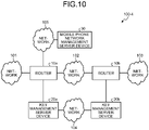
- FIG. 10 is a diagram illustrating a system configuration example of a communication system 100-4 according to the fourth arrangement.
- the communication system 100-4 of the fourth arrangement includes the routers 10a and 10b, the key management server devices 20a and 20b, the mobile phone network management server device 30, and the networks 101 to 105.
- the network 106 between the mobile phone network management server device 30 and the router 10b is deleted from the configuration of the first arrangement.
- FIG. 11 is a diagram illustrating a function configuration example of the router 10b that decrypts a packet according to the fourth arrangement.
- the router 10b of the fourth arrangement includes the packet reception processing module 12, the storage control module 15, the storage 16, the forward processing module 17, the decryption key reception processing module 18, and the decryption processing module 19.
- the router 10b does not include the receiving module 11.
- the decryption processing module 19 determines whether the received packet is encrypted from a header or the like of the packet. When the packet is encrypted, the decryption processing module 19 acquires the decryption key and performs the decryption process in a similar manner to the first arrangement. Other operations of the router 10b are similar to those of the first arrangement.
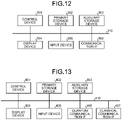
- FIG. 12 is a diagram illustrating a hardware configuration example of the router 10 according to the first to fourth arrangements.
- the router 10 includes a control device 301, a primary storage device 302, an auxiliary storage device 303, a display device 304, an input device 305, and a communication interface (IF) 306.
- IF communication interface
- the control device 301, the primary storage device 302, the auxiliary storage device 303, the display device 304, the input device 305, and the communication IF 306 are connected together via a bus 310.
- the control device 301 executes a computer program read into the primary storage device 302 from the auxiliary storage device 303.
- the primary storage device 302 is a memory such as a read only memory (ROM) and a random access memory (RAM).
- the auxiliary storage device 303 is, for example, a hard disk drive (HDD) or a memory card.
- the display device 304 displays a state or the like of the router 10.
- the input device 305 receives an input from a user.
- the communication IF 306 is an interface to be connected to the networks 101 to 103 and 105 to 107 and the key management server device 20. Note that the router 10 does not have to include the display device 304 and the input device 305. When the router 10 does not include the display device 304 and the input device 305, for example, a display function and an input function of an external terminal connected via the communication IF 306 may be used.
- FIG. 13 is a diagram illustrating a hardware configuration example of the key management server device 20 according to the first to fourth arrangements.
- the key management server device 20 of the first to fourth arrangements includes a control device 401, a primary storage device 402, an auxiliary storage device 403, a display device 404, an input device 405, a quantum communication IF 406, and a classical communication IF 407.
- the control device 401, the primary storage device 402, the auxiliary storage device 403, the display device 404, the input device 405, the quantum communication IF 406, and the classical communication IF 407 are connected together via a bus 410.
- the control device 401 executes a computer program read into the primary storage device 402 from the auxiliary storage device 403.
- the primary storage device 402 is a memory such as a ROM and a RAM.
- the auxiliary storage device 403 is, for example, an HDD or a memory card.
- the display device 404 displays a state or the like of the key management server device 20.
- the input device 405 receives an input from a user. Note that the key management server device 20 does not have to include the display device 404 and the input device 405.
- the quantum communication IF 406 is an interface to be connected to a quantum cryptographic communication channel (the network 104).
- the classical communication IF 407 is an interface to be connected to a control signal communication channel and the router 10.
- the computer program executed by the router 10 and the key management server device 20 of the first to fourth arrangements is provided as a computer program product by being recorded in a computer-readable storage medium such as a CD-ROM, a memory card, a CD-R, and a digital versatile disc (DVD) in the form of an installable or executable file.
- a computer-readable storage medium such as a CD-ROM, a memory card, a CD-R, and a digital versatile disc (DVD) in the form of an installable or executable file.
- the computer program executed by the router 10 and the key management server device 20 of the first to fourth arrangements may also be stored in a computer connected to a network such as the Internet and may be provided by being downloaded via the network.
- the computer program executed by the router 10 and the key management server device 20 of the first to fourth arrangements may also be provided via a network such as the Internet without being downloaded.
- the computer program executed by the router 10 and the key management server device 20 of the first to fourth arrangements may also be provided by being previously incorporated in a ROM or the like.
- the computer program executed by the router 10 of the first to fourth arrangements is configured by a module including a function achievable by the computer program within the function configuration of the router 10 of the first to fourth arrangements.
- the control device 301 reads and executes the computer program from a storage medium such as the auxiliary storage device 303 such that the function achieved by the computer program is loaded in the primary storage device 302. That is, the function achieved by the computer program is generated on the primary storage device 302.
- the computer program executed by the key management server device 20 of the first to fourth arrangements is configured by a module including a function achievable by the computer program within the function configuration of the key management server device 20 of the first and second arrangements.
- the control device 401 reads and executes the computer program from a storage medium such as the auxiliary storage device 403 such that the function achieved by the computer program is loaded in the primary storage device 402. That is, the function achieved by the computer program is generated on the primary storage device 402.
- the functions of the router 10 and the key management server device 20 of the first to fourth arrangements may be partially or wholly achieved by hardware such as an integrated circuit (IC).
- IC integrated circuit
- the IC is, for example, a processing module that executes dedicated processing.
- each processor may achieve one of the functions or two or more of the functions.
- the above router 10 may be a switch that forwards frames (packets) at L2 layer. That is, the above arrangements can be applied to a forwarding device such as a router, a switch, and a gateway.
- packets may be encrypted and decrypted partially, not entirely.
- the uppermost layer protocol is encrypted partially other than a specified condition or entirely, out of protocols instructed to be encrypted or decrypted.
- a data portion (payload portion) of the uppermost layer protocol may be encrypted or decrypted.
- a UDP data portion (payload portion) excluding a UDP header may be encrypted and decrypted. If the entire packet is encrypted, a problem occurs in forwarding the packet, or it becomes difficult to specify a decryption target under the same conditions on the decryption side.
- the mobile phone network management server device 30 may specify a portion to be encrypted or decrypted.
- the mobile phone network management server device 30 may notify the router 10 of an encryption target portion (decryption target portion) including a start position and an end position to perform encryption or decryption in a packet, together with encryption/decryption conditions for each flow.
- the start position and the end position may be notified, for example, using the number of bytes (the number of octets) of the offset from the start of the packet.
- the router 10 encrypts or decrypts the specified portion of the packet based on such an instruction.
- the encryption target portion (decryption target portion) may be transmitted by being embedded in a frame header or data.
- a portion not to be encrypted (portion not to be decrypted), not the encryption target portion (decryption target portion) may be transmitted.
- the encryption processing module 13 of the router 10a (the decryption processing module 19 of the router 10b) recalculates an Ethernet checksum since data is changed by encryption (decryption). If the checksums of IPv4, UDP, TCP, and other protocols are changed, the checksums may be recalculated and provided.
Abstract
According to an arrangement, a forwarding device (10b), which is connected to a key management server device (20b) configured to generate a decryption key by using quantum key distribution, includes a receiving module (11), a packet reception processing module (12), a decryption processing module (19), and a forward processing module (17). The receiving module (11) is configured to receive information specifying a decryption target packet from a mobile phone network management server device (30). The packet reception processing module (12) is configured to receive a reception packet. The decryption processing module (19) is configured to decrypt the reception packet when the reception packet is the decryption target packet specified from the mobile phone network management server device (30). The forward processing module (17) is configured to forward the decrypted reception packet or the undecrypted reception packet.
Description
- The present disclosure relates to a forwarding device, a key management server device, a communication system, a forwarding method, and a computer-readable medium.
- An application programming interface (API) is used in acquiring encryption keys/decryption keys generated from key management server devices by using quantum key distribution (QKD). When receiving a one-time encrypted packet, a forwarding device (or a host) such as a router acquires a decryption key from a key management server device by using the API and decrypts the packet.
- However, in the conventional techniques described above, it is difficult to perform QKD encryption and decryption without degrading the communication performance of a mobile phone network.
-
-
FIG. 1 is a diagram illustrating a system configuration example of a communication system according to a first arrangement; -
FIG. 2 is a diagram illustrating a function configuration example of a router that encrypts a packet according to the first arrangement; -
FIG. 3 is a diagram illustrating a function configuration example of a router that decrypts a packet according to the first arrangement; -
FIG. 4 is a diagram illustrating a function configuration example of a key management server device that supplies an encryption key according to the first arrangement; -
FIG. 5 is a diagram illustrating a function configuration example of a key management server device that supplies a decryption key according to the first arrangement; -
FIG. 6 is a diagram for explaining an example of a communication method according to the first arrangement; -
FIG. 7 is a diagram illustrating a system configuration example of a communication system according to a second arrangement; -
FIG. 8 is a diagram illustrating a function configuration example of a router that receives a route change instruction according to the second arrangement; -
FIG. 9 is a diagram for explaining a system configuration example of a communication system and an example of a communication method according to a third arrangement; -
FIG. 10 is a diagram illustrating a system configuration example of a communication system according to a fourth arrangement; -
FIG. 11 is a diagram illustrating a function configuration example of a router that decrypts a packet according to the fourth arrangement; -
FIG. 12 is a diagram illustrating a hardware configuration example of the router according to the first to fourth arrangements; and -
FIG. 13 is a diagram illustrating a hardware configuration example of the key management sever device according to the first to fourth arrangements. - According to an arrangement, a forwarding device, which is connected to a key management server device configured to generate a decryption key by using quantum key distribution, includes a receiving module, a packet reception processing module, a decryption processing module, and a forward processing module. The receiving module is configured to receive information specifying a decryption target packet from a mobile phone network management server device. The packet reception processing module is configured to receive a reception packet. The decryption processing module is configured to decrypt the reception packet when the reception packet is the decryption target packet specified from the mobile phone network management server device. The forward processing module is configured to forward the decrypted reception packet or the undecrypted reception packet.
- Hereinafter, arrangements of a forwarding device, a key management server device, a communication system, a forwarding method, and a computer program product will be described in detail with reference to the accompanying drawings.
- Note that a packet indicates a transmission unit of information transmitted and received via a network, and frames at L2, and segments and datagrams at L4 are also referred to as packets for the sake of convenience in the description of the following arrangements. Those referred to as packets include information such as headers and footers at L2.
- First, a system configuration example of a communication system of a first arrangement will be described.
-
FIG. 1 is a diagram illustrating a system configuration example of acommunication system 100 according to the first arrangement. Thecommunication system 100 of the first arrangement includesrouters management server devices management server device 30, andnetworks 101 to 106. - Hereinafter, the
routers management server devices - The
routers network 102. Thenetwork 102 is, for example, a network in a mobile phone network. - The
router 10a is also connected to thenetwork 101 so as to forward a packet received through thenetwork 101 to therouter 10b. Therouter 10b is also connected to thenetwork 103 so as to forward the packet forwarded from therouter 10a to an external device connected to thenetwork 103. - In the first arrangement, a case in which the
communication system 100 controls communication through thenetworks 101 to 106 included in the mobile phone network will be described below. - For example, the
routers networks - For example, the
routers networks
For example, for a network configuration using the Distributed Unit (DU), therouters networks - For instance, in the backhaul and the midhaul, user data is transmitted and received via a GTP-U (GTP user data tunneling; GPRS Tunneling Protocol; GPRS: General Packet Radio Service) protocol. In the fronthaul, user data is transmitted and received via an eCPRI protocol.
- The
router 10a is connected to the keymanagement server device 20a. Therouter 10b is connected to the keymanagement server device 20b. Therouter 10a acquires an encryption key for encrypting the packet to be forwarded to therouter 10b from the keymanagement server device 20a. Meanwhile, therouter 10b acquires a decryption key for decrypting the packet received from therouter 10a from the keymanagement server device 20b. - Although the arrangements describe packet encryption and decryption processes for the sake of convenience, the packet encryption and decryption processes do not necessarily have to be performed. In some applications, the
router 10a may attach authentication data to the packet without encrypting the packet, and therouter 10b may verify the authentication data. In any case, therouter 10a acquires a key from the keymanagement server device 20a along with the packet forwarding process, and therouter 10b acquires a key corresponding to the key used in therouter 10a from the keymanagement server device 20b. - Note that the router 10 and the key management server device 20 may be mounted in the same housing as one device, or may be mounted as separate devices.
- The key
management server devices network 104. Thenetworks management server devices management server devices management server devices - The mobile phone network
management server device 30 is connected to therouter 10a via thenetwork 105. The mobile phone networkmanagement server device 30 transmits information specifying a packet to be encrypted to therouter 10a. The mobile phone networkmanagement server device 30 is also connected to therouter 10b via thenetwork 106. The mobile phone networkmanagement server device 30 transmits information specifying a packet to be decrypted to therouter 10b. - Note that the
networks networks - The packets to be encrypted and decrypted are specified based on, for instance, a TEID (an identifier for a tunnel endpoint) field included in a GTP-U header, a QFI (an identifier indicating the quality-of-service of a flow) field, and a PC_ID (an identifier for continuous IQ data; e.g., a physical channel, layer, and antenna port) included in an eCPRI protocol. When the core network device is the EPC, the mobile phone network
management server device 30 may specify a bearer identifier (Evolved Packet System (EPS) Bearer ID; EBI) instead of directly specifying the TEID. An extended Antenna-Carrier (eAxC) identifier (composed of a combination of a DU port identifier, a band sector identifier, a component carrier, and a RU port identifier) defined in O-RAN fronthaul specifications may be used for the PC_ID. - The mobile phone network
management server device 30 is, for example, the core network device included in the backhaul in the mobile phone network. More specifically, in the case of the 5G core, at least one of an Access and Mobility Management Function (AMF) for configuring setting over an N2 interface, a Session Management Function (SMF) for configuring setting over an N4 interface, a Policy Control Function (PCF) for providing policy control, and an Application Function (AF) for receiving a request from the outside serves as the mobile phone networkmanagement server device 30. Note that a user or an operator may set that data needs to be encrypted from the outside via the AF. In this case, an external server that configures such setting can also be considered as the mobile phone networkmanagement server device 30. Additionally, in the case of the EPC, a Policy and Charging Rules Function (PCRF), described in 3GPP TS23.401, for providing policy management, or a Policy and Charging Enforcement Function (PCEF) for providing communication control serves as the mobile phone networkmanagement server device 30. - When the fronthaul is encrypted, an instruction may be given from the mobile phone network
management server device 30 having information of a physical position of an antenna, a distance (may be a value estimated from delay) to the antenna, and confidentiality of an application installed under the antenna, separately from the above configuration, as a server to specify the PC_ID. - The mobile phone network
management server device 30 uniquely specifies a series of packets transmitted and received between specific nodes or specific applications, instructs therouter 10a to encrypt the specified packets (flows, bearers, and slices), and instructs therouter 10b to decrypt the specified packets (flows, bearers, and slices). Note that the target of encryption or decryption specified by the mobile phone networkmanagement server device 30 may be one packet as well as a plurality of packets (flows). - The mobile phone network
management server device 30 can further specify a flow not to be encrypted for therouter 10a, and a flow not to be decrypted for therouter 10b. - The
router 10a may obtain information such as a Secure Application Entity (SAE) ID of therouter 10b together with the instruction from the mobile phone networkmanagement server device 30, or may identify the SAE ID of therouter 10b based on the instruction. - To instruct the
router 10a from the mobile phone networkmanagement server device 30, for example, an N2 interface or an N4 interface described in GPP TS23.501, Diameter, GTP-control (GTP-C), REST, eCPRI, and NETCONF are used. In the case of the N2 interface and the N4 interface, a protocol used for setting is, for instance, a Packet Forwarding Control Protocol (PFCP) for the N4 interface, and a Next Generation Application Protocol (NGAP) for the N2 interface. Note that whether to perform encryption (decryption), its method or the like may be specified as some of Quality of Service (QoS) parameters in the case of the backhaul or the midhaul. Additionally, for example, the mobile phone networkmanagement server device 30 and therouter 10a may share a file and a memory, through which the mobile phone networkmanagement server device 30 may give the instruction to therouter 10a. The same applies to the instruction to therouter 10b from the mobile phone networkmanagement server device 30. -
FIG. 2 is a diagram illustrating a function configuration example of therouter 10a that encrypts a packet according to the first arrangement. Therouter 10a of the first arrangement includes a receivingmodule 11, a packetreception processing module 12, anencryption processing module 13, an encryption key reception processing module 14, astorage control module 15, astorage 16, and aforward processing module 17. - The receiving
module 11 receives, for example, information specifying a packet to be encrypted (encryption target packet) from the mobile phone networkmanagement server device 30. The receivingmodule 11 also receives, for example, information specifying a packet not to be encrypted from the mobile phone networkmanagement server device 30. More specifically, for instance, the receivingmodule 11 may receive the information specifying (instructing) the encryption target packet (or the encryption non-target packet) as some of the QoS parameters of packet communication from the mobile phone networkmanagement server device 30. When receiving the instruction from the mobile phone networkmanagement server device 30, the receivingmodule 11 informs theencryption processing module 13 whether to encrypt the instructed packet. - When receiving a packet from the
network 101, the packetreception processing module 12 inputs the packet to theencryption processing module 13. - When the received packet is instructed to be encrypted by the mobile phone network
management server device 30, theencryption processing module 13 inputs a request to read an encryption key having a specified key length to thestorage control module 15, and acquires the encryption key from thestorage control module 15. Theencryption processing module 13 then encrypts the packet, and inputs the encrypted packet to theforward processing module 17. Meanwhile, when the received packet is instructed not to be encrypted by the mobile phone networkmanagement server device 30, theencryption processing module 13 inputs the packet to theforward processing module 17 without giving the encryption process. - When receiving an encryption key from the key
management server device 20a, the encryption key reception processing module 14 inputs the encryption key to thestorage control module 15. - When receiving the encryption key from the encryption key reception processing module 14, the
storage control module 15 stores the encryption key in thestorage 16. Additionally, when receiving a request to read the encryption key having a specified key length from theencryption processing module 13, thestorage control module 15 reads the encryption key having the specified key length from thestorage 16, and inputs the encryption key and the key identifier identifying the encryption key to theencryption processing module 13. - Note that the
storage control module 15 may keep acquiring the encryption key from the keymanagement server device 20a via the encryption key reception processing module 14 independently of the operation of theencryption processing module 13. Alternatively, thestorage control module 15 may acquire the encryption key from the keymanagement server device 20a via the encryption key reception processing module 14 when instructed by theencryption processing module 13. - The encryption key is acquired, for example, by using a communication protocol such as ETSI GS QKD 014. The encryption key may be also acquired, for example, via a key file generated by the key
management server device 20a. Additionally, the encryption key may be acquired, for example, on a shared memory when therouter 10a and the keymanagement server device 20a are mounted in the same housing as one device. - When receiving the encrypted packet or the unencrypted packet from the
encryption processing module 13, theforward processing module 17 forwards the packet to therouter 10b through thenetwork 102. -
FIG. 3 is a diagram illustrating a function configuration example of therouter 10b that decrypts a packet according to the first arrangement. Therouter 10b basically performs a similar operation to that of therouter 10a. Therouters router 10a performs encryption, therouter 10b performs decryption. Therouter 10b of the first arrangement includes the receivingmodule 11, the packetreception processing module 12, thestorage control module 15, thestorage 16, theforward processing module 17, a decryption keyreception processing module 18, and adecryption processing module 19. - A packet header includes the presence/absence of encryption. In the presence of encryption, the packet header includes a key identifier and an encryption algorithm of a key used for encryption. When a payload is only partially encrypted, the packet header includes information identifying the encrypted region.
- The receiving
module 11 receives, for example, information specifying a packet to be decrypted (decryption target packet) from the mobile phone networkmanagement server device 30. The receivingmodule 11 also receives, for example, information specifying a packet not to be decrypted from the mobile phone networkmanagement server device 30. More specifically, for instance, the receivingmodule 11 may receive the information specifying (instructing) the decryption target packet (or the decryption non-target packet) as some of the QoS parameters of packet communication from the mobile phone networkmanagement server device 30. When receiving the instruction from the mobile phone networkmanagement server device 30, the receivingmodule 11 informs thedecryption processing module 19 whether to decrypt the instructed packet. - When receiving the packet from the
network 102, the packetreception processing module 12 inputs the packet to thedecryption processing module 19. - Meanwhile, the decryption key
reception processing module 18 acquires a decryption key from the keymanagement server device 20b independently of the packet reception process. When receiving the decryption key from the keymanagement server device 20b, the decryption keyreception processing module 18 inputs the decryption key to thestorage control module 15. - The decryption key is acquired, for example, by using a communication protocol such as ETSI GS QKD 014. The decryption key may be also acquired, for example, via a key file generated by the key
management server device 20b. Additionally, the decryption key may be acquired, for example, through a shared memory when therouter 10b and the keymanagement server device 20b are mounted in the same housing as one device. - When receiving the decryption key from the decryption key
reception processing module 18, thestorage control module 15 stores the decryption key in thestorage 16. Thestorage 16 accumulates decryption keys independently of the packet reception process. When receiving a request to read the decryption key from thedecryption processing module 19, thestorage control module 15 reads the decryption key from thestorage 16, and inputs the decryption key to thedecryption processing module 19. - Note that the
storage control module 15 keeps acquiring the decryption key from the keymanagement server device 20b via the decryption keyreception processing module 18 independently of the operation of thedecryption processing module 19. This enables thedecryption processing module 19 to decrypt the packet by using the decryption key supplied from the keymanagement server device 20b without requesting the keymanagement server device 20b to generate the decryption key. - The
decryption processing module 19 decrypts the packet instructed from the receivingmodule 11. In decrypting the packet, thedecryption processing module 19 extracts identification information (typically, the key identifier) of the decryption key corresponding to the encryption key used for encrypting the packet from header information or the like of the packet, and acquires the decryption key corresponding to the identification information from thestorage 16 via thestorage control module 15. - When the
storage 16 does not have the decryption key corresponding to the encryption key (when the decryption key has not been supplied from the keymanagement server device 20b), thestorage control module 15 requests the decryption key from the keymanagement server device 20b via the decryption keyreception processing module 18. When the decryption key is inputted from the decryption keyreception processing module 18, thestorage control module 15 directly inputs the decryption key to thedecryption processing module 19 without storing the decryption key in thestorage 16. This allows the decryption key to be given to thedecryption processing module 19 as quickly as possible, thereby quickly performing the decryption process. - When the decryption key for decrypting the packet has not been supplied from the key
management server device 20b at the time of packet decryption, thedecryption processing module 19 may wait for a predetermined time and request thestorage control module 15 to read the decryption key. - When the decryption key cannot be acquired even after a predetermined number of requests for the
storage control module 15 to read the decryption key, thedecryption processing module 19 discards the packet without decrypting the packet. Additionally, when the decryption key for decrypting the packet has not been supplied from the keymanagement server device 20b at the time of packet decryption, thedecryption processing module 19 may wait for a notification from thestorage control module 15 for a predetermined time. When receiving no notification after passage of the predetermined time, thedecryption processing module 19 may discard the packet without decrypting the packet. - When acquiring the decryption key from the
storage control module 15, thedecryption processing module 19 decrypts the packet and inputs the decrypted packet to theforward processing module 17. - When receiving the decrypted packet from the
decryption processing module 19, theforward processing module 17 forwards the packet to the external device connected to thenetwork 103. -
FIG. 4 is a diagram illustrating a function configuration example of the keymanagement server device 20a that supplies an encryption key according to the first arrangement. The keymanagement server device 20a of the first arrangement includes a key distribution processing module 21, astorage 22, a controlsignal processing module 23, an encryptionkey generation module 24, and asupply module 25. - The key distribution processing module 21 shares a bit string with the key
management server device 20b via thenetwork 104 by using quantum key distribution (quantum cryptography). Note that the key distribution processing module 21 may be mounted separately from the keymanagement server device 20a as a quantum key distribution processing device. - The
storage 22 accumulates bit strings shared by the key distribution processing module 21. - The control
signal processing module 23 transmits the control signal including the key information such as the identification information (typically, the key identifier), the key length, and offset information of the encryption key (the decryption key in the keymanagement server device 20b) to the keymanagement server device 20b that generates the decryption key, in addition to control regarding the sharing of the bit string. The offset information is information indicating where to extract the encryption key (the decryption key) from the shared bit string. - The encryption
key generation module 24 generates the encryption key according to a request for the encryption key from therouter 10a or autonomously. For example, the key length of the encryption key is specified by the request for the encryption key from therouter 10a. Alternatively, for instance, the encryptionkey generation module 24 autonomously generates the encryption key having a predetermined key length. The encryptionkey generation module 24 extracts the encryption key having the key length from the bit string to generate the encryption key, and generates the key identifier identifying the encryption key. - The
supply module 25 supplies therouter 10a with the encryption key generated by the encryptionkey generation module 24 according to the request for the encryption key from therouter 10a or autonomously. The encryption key is supplied to therouter 10a using the bit string (key value) indicating the encryption key itself and the key identifier identifying the encryption key. -
FIG. 5 is a diagram illustrating a function configuration example of the keymanagement server device 20b that supplies a decryption key according to the first arrangement. The keymanagement server device 20b of the first arrangement includes a key distribution processing module 21, astorage 22, a controlsignal processing module 23, asupply module 25, and a decryptionkey generation module 26. - The key distribution processing module 21 shares the bit string with the key
management server device 20a via thenetwork 104 by using quantum key distribution (quantum cryptography). Note that the key distribution processing module 21 may be mounted separately from the keymanagement server device 20b as a quantum key distribution processing device. - The
storage 22 accumulates the bit strings shared by the key distribution processing module 21. - The control
signal processing module 23 receives the control signal including the key information such as the identification information (typically, the key identifier), the key length, and the offset information of the decryption key (the encryption key in the keymanagement server device 20a) from the keymanagement server device 20a, in addition to control regarding the sharing of the bit string. - Upon receiving the control signal, the decryption
key generation module 26 generates the decryption key corresponding to the encryption key from the bit string on the basis of the key identification information and the key length without waiting for a request to generate the decryption key from therouter 10b. This allows the decryption key to be acquired more quickly when therouter 10b decrypts the packet received from therouter 10a. Consequently, the forward throughput/forward speed of therouter 10b can be improved. Note that the bit position to extract the decryption key from the shared bit string is specified, for example, by the offset information included in the control signal. - The
supply module 25 supplies the decryption key generated by the decryptionkey generation module 26 to therouter 10b. -
FIG. 6 is a diagram for explaining an example of a communication method according to the first arrangement. First, the receivingmodule 11 of therouter 10a receives information specifying a packet to be encrypted from the mobile phone network management server device 30 (step S1-1). Meanwhile, the receivingmodule 11 of therouter 10b receives information specifying a packet to be decrypted from the mobile phone network management server device 30 (step S1-2). - Subsequently, the packet
reception processing module 12 of therouter 10a receives a packet from the external device connected to the network 101 (step S2). Theencryption processing module 13 of therouter 10a then transmits a request to generate an encryption key having the same length as the packet received by the process at the step S2 to the keymanagement server device 20a (step S3). - Subsequently, in the key
management server device 20a, the encryptionkey generation module 24 generates the encryption key, and the controlsignal processing module 23 notifies the keymanagement server device 20b of the key information (the key identification information and the key length) of the generated encryption key (step S4). - The
supply module 25 of the keymanagement server device 20a then supplies the encryption key to therouter 10a (step S5-1). Meanwhile, in the keymanagement server device 20b, the decryptionkey generation module 26 generates a decryption key corresponding to the encryption key supplied by the process at the step S5-1 from the bit string shared with the keymanagement server device 20a on the basis of the key identification information and the key length notified at the step S4 without waiting for a request to generate the decryption key from therouter 10b. Thesupply module 25 supplies (pushes) the decryption key to therouter 10b (step S5-2). Note that the request to generate the decryption key is, for example, calling of Get key or Get key with key IDs of a Key Delivery API described in ETSI GS QKD 014. Alternatively, therouter 10b may issue the request to generate the decryption key to the key management server device on TCP, UDP, or other transport protocols. When therouter 10b and the key management server device share a file system and a memory, the request to generate the decryption key may be issued through interprocess communication. - Subsequently, when the packet received by the process at the step S2 is the packet specified by the process at the step S1-1, the
encryption processing module 13 of therouter 10a encrypts the packet by using the encryption key supplied by the process at the step S5-1, and forwards the encrypted packet to therouter 10b through the network 102 (step S6). Note that a packet not specified by the process at the step S1-1 is forwarded without being encrypted at the step S6. - Subsequently, the packet
reception processing module 12 of therouter 10b receives the packet forwarded by the process at the step S6. When the packet forwarded by the process at the step S6 is the packet specified by the process at the step S1-2, thedecryption processing module 19 decrypts the packet by using the decryption key supplied by the process at the step S5-2, and theforward processing module 17 forwards the packet to the external device connected to the network 103 (step S7). Note that a packet not specified by the process at the step S1-2 is forwarded without being decrypted at the step S7. - As described above, the
communication system 100 of the first arrangement includes the mobile phone networkmanagement server device 30, the keymanagement server device 20a (first key management server device), the keymanagement server device 20b (second key management server device), therouter 10a (first forwarding device), and therouter 10b (second forwarding device). - In the
router 10a (first forwarding device), the receivingmodule 11 receives the information specifying the encryption target packet from the mobile phone networkmanagement server device 30. The packetreception processing module 12 receives a first reception packet through the network 101 (first network). When the first reception packet is the encryption target packet, theencryption processing module 13 transmits the request to generate the encryption key to the first key management server device, and encrypts the first reception packet by using the encryption key supplied from the first key management server device. The forward processing module 17 (first forward processing module) forwards the encrypted first reception packet or the unencrypted first reception packet to the second forwarding device through the network 102 (second network). - In the key
management server device 20a (first key management server device), the key distribution processing module 21 shares the bit string by quantum key distribution. When the mobile phone networkmanagement server device 30 specifies the encryption target packet for the first forwarding device, the encryptionkey generation module 24 generates the encryption key for encrypting the encryption target packet from the bit string in response to the request to generate the encryption key transmitted from the first forwarding device. The controlsignal processing module 23 transmits the control signal including the key identification information for identifying the encryption key and the key length indicating the length of the encryption key to the second key management server device. - In the
router 10b (second forwarding device), the packetreception processing module 12 receives a second reception packet through the second network. When the second reception packet is the decryption target packet, thedecryption processing module 19 decrypts the second reception packet by using the decryption key supplied from the second key management server device without transmitting the request to generate the decryption key to the second key management server device. The forward processing module 17 (second forward processing module) forwards the decrypted second reception packet or the undecrypted second reception packet. - In the key
management server device 20b (second key management server device), the key distribution processing module 21 shares the bit string by quantum key distribution. The controlsignal processing module 23 receives the control signal. Upon receiving the control signal, the decryptionkey generation module 26 generates the decryption key corresponding to the encryption key from the bit string based on the key identification information and the key length without waiting for the request to generate the decryption key from the second forwarding device. Thesupply module 25 supplies the decryption key to the second forwarding device. - Consequently, the
communication system 100 of the first arrangement can perform the QKD encryption and decryption without degrading the communication performance of a mobile phone network. More specifically, the above configuration enables therouter 10a (QKD compatible router) to receive control information (the information specifying the encryption target packet (flow)) from the mobile phone network. Therouter 10a can thereby identify traffic to be protected by the QKD encryption key within traffic passing through therouter 10a. The control information from the mobile phone network is also transmitted to the QKD keymanagement server devices management server devices - In the conventional technique, a key distribution processing speed using QKD is slower than a communication speed of the mobile phone network. Thus, the communication performance of the mobile phone network is degraded if the encryption router (VPN router) using QKD is installed at a main point in the network.
- While the case in which the
single router 10b is connected to the keymanagement server device 20b is described in the example ofFIG. 1 , a plurality of therouters 10b may be connected to the keymanagement server device 20b. When therouters 10b are connected to the keymanagement server device 20b, the control signal further includes router identification information identifying therouter 10b to be supplied with the decryption key. The router identification information includes, for example, an IP address, a port number, and a host name of each router 10. Thesupply module 25 supplies the decryption key to the router identified by the router identification information. - Next, a modification of the first arrangement will be described. In the modification, a description similar to that of the first arrangement will be omitted, and only different points from those of the first arrangement will be described.
- In the modification, a case in which a SAE ID is generated and given for each flow will be described.
- When a flow to be encrypted is specified from the mobile phone network
management server device 30, the receivingmodule 11 of therouter 10a of the modification generates a SAE ID corresponding to the flow, and additionally sets the SAE ID to itself. The receivingmodule 11 generates a SAE ID corresponding to the flow by, for example, combining a SAE ID set to therouter 10a itself and information identifying the flow. - For example, the receiving
module 11 connects the SAE ID set to therouter 10a itself and the information identifying the flow to generate a new SAE ID. Additionally, for instance, the receivingmodule 11 connects the SAE ID set to therouter 10a itself and a hash value of the information identifying the flow to generate a new SAE ID. Moreover, for example, the receivingmodule 11 generates a hash value obtained from the SAE ID set to therouter 10a itself and the information identifying the flow as a new SAE ID. - The new SAE ID corresponding to the flow may be global unique, or may be unique (local unique) only between the
routers module 11 of therouter 10a receiving the instruction from the mobile phone networkmanagement server device 30 generates the SAE ID corresponding to the flow to be encrypted according to a certain rule. The receivingmodule 11 of therouter 10b also generates a SAE ID corresponding to a flow to be decrypted in a similar method. - The SAE IDs generated by the
respective receiving modules 11 may be transmitted and received, for instance, between therouters router 10a may estimate the SAE ID to be newly generated by therouter 10b from the SAE ID of therouter 10b itself and the information identifying the flow to be decrypted by therouter 10b. The same applies to therouter 10b. - Next, a second arrangement will be described. In the second arrangement, a description similar to that of the first arrangement will be omitted, and only different points from those of the first arrangement will be described.
- In the second arrangement, a case in which a router that receives a route change instruction is added will be described.
-
FIG. 7 is a diagram illustrating a system configuration example of a communication system 100-2 according to the second arrangement. The communication system 100-2 of the second arrangement includes therouters 10a to 10d, the keymanagement server devices management server device 30, and thenetworks 101 to 107. In the second arrangement,routers network 107 are added to the configuration of the first arrangement. Since therouters router 10c will be described later as an example usingFIG. 8 . - In the example in
FIG. 7 , therouters network 107. The packet encrypted by therouter 10a is forwarded to therouter 10b through thenetwork 107. Thenetworks router 10a may be also forwarded to therouter 10b through therouter 10c, thenetwork 102, and therouter 10d without connecting therouters network 107. - Note that a Software Defined Networking (SDN) compatible router and a Network Service Header (NSH) defined by RFC8300 may be used as a method for achieving a route change of the second arrangement. In this case, to cause a specific packet instructed from the mobile phone network
management server device 30 to pass through therouters module 11 gives a NSH header describing a function type and an order of a service to the specific packet. Theforward processing module 17 then forwards the packet specified by the NSH header to therouter 10a. Theforward processing module 17 forwards other packets (packets not instructed from the mobile phone network management server device 30) and a packet received from therouter 10a to thenetwork 102. -
FIG. 8 is a diagram illustrating a function configuration example of therouter 10c that receives a route change instruction according to the second arrangement. Therouter 10c of the second arrangement includes the receivingmodule 11, the packetreception processing module 12, and theforward processing module 17. - The receiving
module 11 receives an instruction (specification) to forward a specific packet to therouter 10a from the mobile phone networkmanagement server device 30. - The
forward processing module 17 forwards the specified packet to therouter 10a. Theforward processing module 17 forwards other packets (packets not instructed from the mobile phone network management server device 30) and a packet received from therouter 10a to thenetwork 102. - The
routers management server device 30, or do not have to be connected to the mobile phone networkmanagement server device 30.FIG. 7 illustrates a configuration in which therouters management server device 30. When therouters management server device 30, therouters management server device 30 in a similar manner to the first arrangement. - When the
routers management server device 30, therouter 10a performs encryption according to a predetermined rule, for example, by always encrypting the received packet or encrypting only a specific packet. The same applies to therouter 10b that performs decryption. - Next, a third arrangement will be described. In the third arrangement, a description similar to that of the first arrangement will be omitted, and only different points from those of the first arrangement will be described.
- In the third arrangement, a case in which one or more key management server devices 20 exist between the key
management server devices -
FIG. 9 is a diagram for explaining an example of a system configuration of a communication system 100-3 and a communication method according to the third arrangement. In the example ofFIG. 9 , two keymanagement server devices management server devices - In the third arrangement, the key
management server device 20a shares the bit string with the keymanagement server device 20e via a quantum cryptographic communication channel. Additionally, the keymanagement server device 20b shares the bit string with the keymanagement server device 20f via a quantum cryptographic communication channel. Thus, the keymanagement server devices - In the third arrangement, the control
signal processing module 23 of the keymanagement server device 20a protects (encrypts) the key information used for decrypting the packet in therouter 10b by using the bit string shared with the adjacent keymanagement server device 20e, and transmits the key information to the keymanagement server device 20e. Note that the key information of the third arrangement includes not only the key identification information and the key length but also the key value used for the decryption key. The controlsignal processing module 23 of the keymanagement server device 20e transmits the key information used for decrypting the packet in therouter 10b to the adjacent keymanagement server device 20f in a similar manner. As described above, the key information used for decrypting the packet forwarded by therouter 10a is delivered to the keymanagement server device 20b in a bucket brigade manner through the key management server devices 20 (step S4-1 to step S4-3). - The
supply module 25 of the keymanagement server device 20a supplies the encryption key to therouter 10a (step S5-1). Meanwhile, in the keymanagement server device 20b, the decryptionkey generation module 26 generates the decryption key by using the key value included in the key information notified by the process at the step S4-3 without waiting for a request to generate the decryption key from therouter 10b. Thesupply module 25 supplies (pushes) the decryption key to therouter 10b (step S5-2). - Note that a description on the steps S1-1, S1-2, S2, S3, S6 and S7, which is similar to that of the first arrangement (see
FIG. 6 ), is omitted. - The key
management server devices router 10b. That is, the keymanagement server device 20a may newly generate the decryption key to be used in therouter 10b, protect the decryption key by using the bit string shared with the keymanagement server device 20e, and transmit the decryption key to the keymanagement server device 20e. Alternatively, the keymanagement server device 20a may instruct the keymanagement server device 20e to use a portion of the bit string shared with the keymanagement server device 20e as the key value of the decryption key used in therouter 10b. - Moreover, the control
signal processing module 23 of the keymanagement server device 20a may directly transmit the key identification information and the key length shared between the keymanagement server devices management server device 20b, without being relayed in a bucket brigade manner by the keymanagement server devices - When no additional key management server device 20 exists between the key
management server devices FIG. 1 , the keymanagement server device 20a may protect (encrypt) the decryption key to be used in therouter 10b by using the bit string shared with the keymanagement server device 20b and transmit the decryption key to the keymanagement server device 20b. - As described above, in the communication system 100-3 of the third arrangement, the key distribution processing module 21 of the key
management server device 20a shares the bit string with the facing keymanagement server device 20e by quantum key distribution. The controlsignal processing module 23 of the keymanagement server device 20a encrypts the decryption key by using the shared bit string, and transmits the control signal including the encrypted decryption key and the key identification information identifying the decryption key to the facing keymanagement server device 20e. - Similarly, the key distribution processing module 21 of the key
management server device 20e shares the bit string with the facing keymanagement server device 20f by quantum key distribution. The controlsignal processing module 23 of the keymanagement server device 20e encrypts the decryption key (the decryption key received from the keymanagement server device 20a) by using the shared bit string, and transmits the control signal including the encrypted decryption key and the key identification information identifying the decryption key to the facing keymanagement server device 20f. - Similarly, the key distribution processing module 21 of the key
management server device 20f shares the bit string with the facing keymanagement server device 20b by quantum key distribution. The controlsignal processing module 23 of the keymanagement server device 20f encrypts the decryption key (the decryption key received from the keymanagement server device 20e) by using the shared bit string, and transmits the control signal including the encrypted decryption key and the key identification information identifying the decryption key to the facing keymanagement server device 20b. - Upon receiving the control signal from the key
management server device 20f, thesupply module 25 of the keymanagement server device 20b supplies the decryption key to therouter 10b without waiting for the request to generate the decryption key from therouter 10b. - Meanwhile, in the
router 10b, the packetreception processing module 12 receives the packet encrypted with the encryption key corresponding to the decryption key identified by the key identification information. Thedecryption processing module 19 decrypts the packet by using the decryption key supplied from the keymanagement server device 20b without requesting the keymanagement server device 20b to generate the decryption key. - Consequently, the communication system 100-3 of the third arrangement can provide similar effects to those of the first arrangement even when the bit string cannot be directly shared between the key
management server devices management server device 20b without receiving the encrypted packet. - Next, a fourth arrangement will be described. In the fourth arrangement, a description similar to that of the first arrangement will be omitted, and only different points from those of the first arrangement will be described.
- In the fourth arrangement, a case in which the mobile phone network
management server device 30 is connected to therouter 10a and is not connected to therouter 10b will be described. -
FIG. 10 is a diagram illustrating a system configuration example of a communication system 100-4 according to the fourth arrangement. The communication system 100-4 of the fourth arrangement includes therouters management server devices management server device 30, and thenetworks 101 to 105. In the fourth arrangement, thenetwork 106 between the mobile phone networkmanagement server device 30 and therouter 10b is deleted from the configuration of the first arrangement. -
FIG. 11 is a diagram illustrating a function configuration example of therouter 10b that decrypts a packet according to the fourth arrangement. Therouter 10b of the fourth arrangement includes the packetreception processing module 12, thestorage control module 15, thestorage 16, theforward processing module 17, the decryption keyreception processing module 18, and thedecryption processing module 19. In the fourth arrangement, therouter 10b does not include the receivingmodule 11. Unlike in the first arrangement, thedecryption processing module 19 determines whether the received packet is encrypted from a header or the like of the packet. When the packet is encrypted, thedecryption processing module 19 acquires the decryption key and performs the decryption process in a similar manner to the first arrangement. Other operations of therouter 10b are similar to those of the first arrangement. - Lastly, hardware configuration examples of the router 10 and the key management server device 20 of the first to fourth arrangements will be described.
-
FIG. 12 is a diagram illustrating a hardware configuration example of the router 10 according to the first to fourth arrangements. The router 10 includes acontrol device 301, aprimary storage device 302, anauxiliary storage device 303, adisplay device 304, aninput device 305, and a communication interface (IF) 306. - The
control device 301, theprimary storage device 302, theauxiliary storage device 303, thedisplay device 304, theinput device 305, and the communication IF 306 are connected together via abus 310. - The
control device 301 executes a computer program read into theprimary storage device 302 from theauxiliary storage device 303. Theprimary storage device 302 is a memory such as a read only memory (ROM) and a random access memory (RAM). Theauxiliary storage device 303 is, for example, a hard disk drive (HDD) or a memory card. - The
display device 304 displays a state or the like of the router 10. Theinput device 305 receives an input from a user. The communication IF 306 is an interface to be connected to thenetworks 101 to 103 and 105 to 107 and the key management server device 20. Note that the router 10 does not have to include thedisplay device 304 and theinput device 305. When the router 10 does not include thedisplay device 304 and theinput device 305, for example, a display function and an input function of an external terminal connected via the communication IF 306 may be used. -
FIG. 13 is a diagram illustrating a hardware configuration example of the key management server device 20 according to the first to fourth arrangements. The key management server device 20 of the first to fourth arrangements includes acontrol device 401, aprimary storage device 402, anauxiliary storage device 403, adisplay device 404, aninput device 405, a quantum communication IF 406, and a classical communication IF 407. - The
control device 401, theprimary storage device 402, theauxiliary storage device 403, thedisplay device 404, theinput device 405, the quantum communication IF 406, and the classical communication IF 407 are connected together via abus 410. - The
control device 401 executes a computer program read into theprimary storage device 402 from theauxiliary storage device 403. Theprimary storage device 402 is a memory such as a ROM and a RAM. Theauxiliary storage device 403 is, for example, an HDD or a memory card. - The
display device 404 displays a state or the like of the key management server device 20. Theinput device 405 receives an input from a user. Note that the key management server device 20 does not have to include thedisplay device 404 and theinput device 405. - The quantum communication IF 406 is an interface to be connected to a quantum cryptographic communication channel (the network 104). The classical communication IF 407 is an interface to be connected to a control signal communication channel and the router 10.
- The computer program executed by the router 10 and the key management server device 20 of the first to fourth arrangements is provided as a computer program product by being recorded in a computer-readable storage medium such as a CD-ROM, a memory card, a CD-R, and a digital versatile disc (DVD) in the form of an installable or executable file.
- The computer program executed by the router 10 and the key management server device 20 of the first to fourth arrangements may also be stored in a computer connected to a network such as the Internet and may be provided by being downloaded via the network.
- The computer program executed by the router 10 and the key management server device 20 of the first to fourth arrangements may also be provided via a network such as the Internet without being downloaded.
- The computer program executed by the router 10 and the key management server device 20 of the first to fourth arrangements may also be provided by being previously incorporated in a ROM or the like.
- The computer program executed by the router 10 of the first to fourth arrangements is configured by a module including a function achievable by the computer program within the function configuration of the router 10 of the first to fourth arrangements. The
control device 301 reads and executes the computer program from a storage medium such as theauxiliary storage device 303 such that the function achieved by the computer program is loaded in theprimary storage device 302. That is, the function achieved by the computer program is generated on theprimary storage device 302. - Additionally, the computer program executed by the key management server device 20 of the first to fourth arrangements is configured by a module including a function achievable by the computer program within the function configuration of the key management server device 20 of the first and second arrangements. The
control device 401 reads and executes the computer program from a storage medium such as theauxiliary storage device 403 such that the function achieved by the computer program is loaded in theprimary storage device 402. That is, the function achieved by the computer program is generated on theprimary storage device 402. - Note that the functions of the router 10 and the key management server device 20 of the first to fourth arrangements may be partially or wholly achieved by hardware such as an integrated circuit (IC). The IC is, for example, a processing module that executes dedicated processing.
- Moreover, when a plurality of processors are used to achieve the functions, each processor may achieve one of the functions or two or more of the functions.
- For example, the above router 10 may be a switch that forwards frames (packets) at L2 layer. That is, the above arrangements can be applied to a forwarding device such as a router, a switch, and a gateway.
- Additionally, for instance, packets may be encrypted and decrypted partially, not entirely. Preferably, the uppermost layer protocol is encrypted partially other than a specified condition or entirely, out of protocols instructed to be encrypted or decrypted. For example, a data portion (payload portion) of the uppermost layer protocol may be encrypted or decrypted. For instance, when encryption and decryption are performed on a flow forwarded over IPv4 and having UDP destination port No. 1234, a UDP data portion (payload portion) excluding a UDP header may be encrypted and decrypted. If the entire packet is encrypted, a problem occurs in forwarding the packet, or it becomes difficult to specify a decryption target under the same conditions on the decryption side. These problems can be solved by encrypting only the data portion.
- Moreover, for example, the mobile phone network
management server device 30 may specify a portion to be encrypted or decrypted. For instance, the mobile phone networkmanagement server device 30 may notify the router 10 of an encryption target portion (decryption target portion) including a start position and an end position to perform encryption or decryption in a packet, together with encryption/decryption conditions for each flow. The start position and the end position may be notified, for example, using the number of bytes (the number of octets) of the offset from the start of the packet. The router 10 encrypts or decrypts the specified portion of the packet based on such an instruction. Additionally, the encryption target portion (decryption target portion) may be transmitted by being embedded in a frame header or data. Moreover, conversely, a portion not to be encrypted (portion not to be decrypted), not the encryption target portion (decryption target portion), may be transmitted. - Additionally, for instance, the
encryption processing module 13 of therouter 10a (thedecryption processing module 19 of therouter 10b) recalculates an Ethernet checksum since data is changed by encryption (decryption). If the checksums of IPv4, UDP, TCP, and other protocols are changed, the checksums may be recalculated and provided. - While certain arrangements have been described, these arrangements have been presented by way of example only, and are not intended to limit the scope of the claims. Indeed, the devices described herein may be embodied in a variety of other forms; furthermore various omissions, substitutions and changes in the form of the devices described herein may be made.
Claims (8)
- A forwarding device (10b) connected to a key management server device (20b) configured to generate a decryption key by using quantum key distribution, the forwarding device comprising:a receiving module (11) configured to receive information specifying a decryption target packet from a mobile phone network management server device (30);a packet reception processing module (12) configured to receive a reception packet;a decryption processing module (19) configured to decrypt the reception packet when the reception packet is the decryption target packet specified from the mobile phone network management server device (30); anda forward processing module (17) configured to forward the decrypted reception packet or the undecrypted reception packet.
- The forwarding device (10b) according to claim 1, wherein
the decryption processing module (19) is configured to decrypt the reception packet by using a decryption key supplied from the key management server device (20b) without transmitting a request to generate the decryption key to the key management server device (20b) when the reception packet is the decryption target packet. - The forwarding device (10b) according to claim 1 or 2, wherein
the mobile phone network management server device (30) is a core network device included in backhaul in a mobile phone network. - The forwarding device (10b) according to claim 3, wherein
the receiving module (11) is configured to receive the information specifying the decryption target packet as some of Quality of Service (QoS) parameters of packet communication from the mobile phone network management server device (30). - A forwarding device (10a) connected to a key management server device (20a) configured to generate an encryption key by using quantum key distribution, the forwarding device (10a) comprising:a receiving module (11) configured to receive information specifying an encryption target packet from a mobile phone network management server device (30);a packet reception processing module (12) configured to receive a reception packet;an encryption processing module (13) configured to transmit a request to generate an encryption key to the key management server device (20a) and to encrypt the reception packet by using the encryption key supplied from the key management server device (20a), when the reception packet is the encryption target packet; anda forward processing module (17) configured to forward the encrypted reception packet or the unencrypted reception packet.
- A key management server device (20a) connected to a forwarding device (10a), the key management server device (20a) comprising:a key distribution processing module (21) configured to share a bit string by quantum key distribution;an encryption key generation module (24) configured to generate an encryption key for encrypting an encryption target packet from the bit string in response to a request to generate the encryption key transmitted from the forwarding device (10a) when a mobile phone network management server device (30) specifies the encryption target packet for the forwarding device (10a); anda control signal processing module (23) configured to transmit a control signal including key identification information identifying the encryption key and a key length indicating a length of the encryption key to a counterpart key management server device (20b).
- A communication system (100) comprising:a mobile phone network management server device (30);a first key management server device (20a);a second key management server device (20b);a first forwarding device (10a); anda second forwarding device (10b),the first forwarding device (10a) comprising:a receiving module (11) configured to receive information specifying an encryption target packet from the mobile phone network management server device (30);a packet reception processing module (12) configured to receive a first reception packet through a first network (101);an encryption processing module (13) configured to transmit a request to generate an encryption key to the first key management server device (20a) and to encrypt the first reception packet by using the encryption key supplied from the first key management server device (20a), when the first reception packet is the encryption target packet; anda first forward processing module (17) configured to forward the encrypted first reception packet or the unencrypted first reception packet to the second forwarding device (10b) through a second network (102),the first key management server device (20a) comprising:a key distribution processing module (21) configured to share a bit string by quantum key distribution;an encryption key generation module (24) configured to generate the encryption key for encrypting the encryption target packet from the bit string in response to the request to generate the encryption key transmitted from the first forwarding device (10a) when the mobile phone network management server device (30) specifies the encryption target packet for the first forwarding device (10a); anda control signal processing module (23) configured to transmit a control signal including key identification information identifying the encryption key and a key length indicating a length of the encryption key to the second key management server device (20b),the second forwarding device (10b) comprising:a packet reception processing module (12) configured to receive a second reception packet through the second network (102);a decryption processing module (19) configured to decrypt the second reception packet when the second reception packet is a decryption target packet; anda second forward processing module (17) configured to forward the decrypted second reception packet or the undecrypted second reception packet, andthe second key management server device (20b) comprising:a key distribution processing module (21) configured to share the bit string by quantum key distribution;a control signal processing module (23) configured to receive the control signal;a decryption key generation module (26) configured to generate a decryption key corresponding to the encryption key from the bit string based on the key identification information and the key length, upon receiving the control signal without waiting for a request to generate the decryption key from the second forwarding device (10b); anda supply module (25) configured to supply the decryption key to the second forwarding device (10b).
- A computer program product comprising a computer-readable medium including programmed instructions, the instructions causing a forwarding device (10b), which is connected to a key management server device (20b) configured to generate a decryption key by using quantum key distribution, to execute:receiving information specifying a decryption target packet from a mobile phone network management server device (30) (S1-2);receiving a reception packet (S6);decrypting the reception packet when the reception packet is the decryption target packet specified from the mobile phone network management server device (30) (S7); andforwarding the decrypted reception packet or the undecrypted reception packet (S7).
Applications Claiming Priority (1)
| Application Number | Priority Date | Filing Date | Title |
|---|---|---|---|
| JP2020186158A JP7395455B2 (en) | 2020-11-06 | 2020-11-06 | Transfer device, key management server device, communication system, transfer method and program |
Publications (1)
| Publication Number | Publication Date |
|---|---|
| EP3996325A1 true EP3996325A1 (en) | 2022-05-11 |
Family
ID=77519058
Family Applications (1)
| Application Number | Title | Priority Date | Filing Date |
|---|---|---|---|
| EP21193345.2A Pending EP3996325A1 (en) | 2020-11-06 | 2021-08-26 | Forwarding device, key management server device, communication system, forwarding method, and computer-readable medium |
Country Status (3)
| Country | Link |
|---|---|
| US (1) | US20220150059A1 (en) |
| EP (1) | EP3996325A1 (en) |
| JP (1) | JP7395455B2 (en) |
Cited By (1)
| Publication number | Priority date | Publication date | Assignee | Title |
|---|---|---|---|---|
| US11516721B1 (en) * | 2021-07-13 | 2022-11-29 | Qualcomm Incorporated | Extended antenna-carrier allocation policy for simplified switching |
Families Citing this family (2)
| Publication number | Priority date | Publication date | Assignee | Title |
|---|---|---|---|---|
| WO2024073144A2 (en) * | 2022-09-30 | 2024-04-04 | Comcast Cable Communications, Llc | Methods and apparatuses for managing a multipath connection |
| CN115955306B (en) * | 2022-12-30 | 2023-11-14 | 北京海泰方圆科技股份有限公司 | Data encryption transmission method and device, electronic equipment and storage medium |
Citations (2)
| Publication number | Priority date | Publication date | Assignee | Title |
|---|---|---|---|---|
| US20170324714A1 (en) * | 2016-05-04 | 2017-11-09 | Cisco Technology, Inc. | Authenticated group context in transitive ip network domains |
| US20190149327A1 (en) * | 2017-11-14 | 2019-05-16 | Alibaba Group Holding Limited | Method and system for quantum key distribution and data processing |
Family Cites Families (9)
| Publication number | Priority date | Publication date | Assignee | Title |
|---|---|---|---|---|
| CN101065940B (en) | 2004-11-29 | 2013-02-20 | 国际商业机器公司 | Relay device and method for communication between communication terminal and server |
| CN108156180B (en) | 2013-06-08 | 2021-04-09 | 科大国盾量子技术股份有限公司 | Communication key distribution method based on Android intelligent mobile terminal |
| CN103916239A (en) | 2014-04-09 | 2014-07-09 | 长春大学 | Quantum secret communication gateway system for financial security network |
| US9998434B2 (en) * | 2015-01-26 | 2018-06-12 | Listat Ltd. | Secure dynamic communication network and protocol |
| GB2534918B (en) | 2015-02-05 | 2019-07-24 | Toshiba Res Europe Limited | A quantum communication system and a quantum communication method |
| CN106161359B (en) * | 2015-04-02 | 2019-09-17 | 阿里巴巴集团控股有限公司 | It authenticates the method and device of user, register the method and device of wearable device |
| WO2018201506A1 (en) | 2017-05-05 | 2018-11-08 | 华为技术有限公司 | Communication method and related device |
| US10554397B2 (en) | 2017-09-27 | 2020-02-04 | The Boeing Company | Quantum-based data encryption |
| US11438148B2 (en) * | 2020-03-27 | 2022-09-06 | Ahp-Tech Inc. | Quantum computing-threat-resistant method and system for use on cryptography key exchanging processes |
-
2020
- 2020-11-06 JP JP2020186158A patent/JP7395455B2/en active Active
-
2021
- 2021-08-26 EP EP21193345.2A patent/EP3996325A1/en active Pending
- 2021-08-31 US US17/463,238 patent/US20220150059A1/en active Pending
Patent Citations (2)
| Publication number | Priority date | Publication date | Assignee | Title |
|---|---|---|---|---|
| US20170324714A1 (en) * | 2016-05-04 | 2017-11-09 | Cisco Technology, Inc. | Authenticated group context in transitive ip network domains |
| US20190149327A1 (en) * | 2017-11-14 | 2019-05-16 | Alibaba Group Holding Limited | Method and system for quantum key distribution and data processing |
Non-Patent Citations (1)
| Title |
|---|
| 3GPP TS23.401 |
Cited By (1)
| Publication number | Priority date | Publication date | Assignee | Title |
|---|---|---|---|---|
| US11516721B1 (en) * | 2021-07-13 | 2022-11-29 | Qualcomm Incorporated | Extended antenna-carrier allocation policy for simplified switching |
Also Published As
| Publication number | Publication date |
|---|---|
| JP2022075398A (en) | 2022-05-18 |
| US20220150059A1 (en) | 2022-05-12 |
| JP7395455B2 (en) | 2023-12-11 |
Similar Documents
| Publication | Publication Date | Title |
|---|---|---|
| EP3996325A1 (en) | Forwarding device, key management server device, communication system, forwarding method, and computer-readable medium | |
| KR102263336B1 (en) | Security Implementation Methods, Devices and Systems | |
| EP2853070B1 (en) | Multi-tunnel virtual private network | |
| US9871766B2 (en) | Secure path determination between devices | |
| US7912063B2 (en) | Secure communications for wireless mesh network access points | |
| WO2018205427A1 (en) | Key configuration method, apparatus and system | |
| US9369550B2 (en) | Protocol for layer two multiple network links tunnelling | |
| CN108601043B (en) | Method and apparatus for controlling wireless access point | |
| US10044841B2 (en) | Methods and systems for creating protocol header for embedded layer two packets | |
| JP2006101051A (en) | Server, vpn client, vpn system, and software | |
| KR100748698B1 (en) | Apparatus and method of packet processing in security communication system | |
| CN110858822B (en) | Media access control security protocol message transmission method and related device | |
| US20220278970A1 (en) | Anonymous communication over virtual, modular and distributed satellite communications network | |
| KR20140122335A (en) | Method for constructing virtual private network, method for packet forwarding and gateway apparatus using the methods | |
| CN101572644A (en) | Data encapsulation method and equipment thereof | |
| CN105337954A (en) | Method and device for encryption and decryption of IP message in satellite communication | |
| US11006346B2 (en) | X2 service transmission method and network device | |
| US20180262473A1 (en) | Encrypted data packet | |
| JP2005244379A (en) | Vpn system, vpn apparatus, and encryption key distribution method used for them | |
| US20220150058A1 (en) | Forwarding device, key management server device, communication system, forwarding method, and computer program product | |
| KR101837064B1 (en) | Apparatus and method for secure communication | |
| JP2005210380A (en) | Method and system for peer-to-peer communication | |
| CN110650476B (en) | Management frame encryption and decryption | |
| US20220400405A1 (en) | Methods and apparatus for reducing communications delay | |
| EP4175227A1 (en) | Security for communication protocols |
Legal Events
| Date | Code | Title | Description |
|---|---|---|---|
| PUAI | Public reference made under article 153(3) epc to a published international application that has entered the european phase |
Free format text: ORIGINAL CODE: 0009012 |
|
| STAA | Information on the status of an ep patent application or granted ep patent |
Free format text: STATUS: REQUEST FOR EXAMINATION WAS MADE |
|
| 17P | Request for examination filed |
Effective date: 20210826 |
|
| AK | Designated contracting states |
Kind code of ref document: A1 Designated state(s): AL AT BE BG CH CY CZ DE DK EE ES FI FR GB GR HR HU IE IS IT LI LT LU LV MC MK MT NL NO PL PT RO RS SE SI SK SM TR |
|
| STAA | Information on the status of an ep patent application or granted ep patent |
Free format text: STATUS: EXAMINATION IS IN PROGRESS |
|
| 17Q | First examination report despatched |
Effective date: 20230928 |