EP3996237A1 - Battery control system, battery pack, electrical vehicle, and id setting method for battery control system - Google Patents
Battery control system, battery pack, electrical vehicle, and id setting method for battery control system Download PDFInfo
- Publication number
- EP3996237A1 EP3996237A1 EP21754243.0A EP21754243A EP3996237A1 EP 3996237 A1 EP3996237 A1 EP 3996237A1 EP 21754243 A EP21754243 A EP 21754243A EP 3996237 A1 EP3996237 A1 EP 3996237A1
- Authority
- EP
- European Patent Office
- Prior art keywords
- battery controller
- battery
- signal path
- high level
- level voltage
- Prior art date
- Legal status (The legal status is an assumption and is not a legal conclusion. Google has not performed a legal analysis and makes no representation as to the accuracy of the status listed.)
- Pending
Links
Images



Classifications
-
- B—PERFORMING OPERATIONS; TRANSPORTING
- B60—VEHICLES IN GENERAL
- B60L—PROPULSION OF ELECTRICALLY-PROPELLED VEHICLES; SUPPLYING ELECTRIC POWER FOR AUXILIARY EQUIPMENT OF ELECTRICALLY-PROPELLED VEHICLES; ELECTRODYNAMIC BRAKE SYSTEMS FOR VEHICLES IN GENERAL; MAGNETIC SUSPENSION OR LEVITATION FOR VEHICLES; MONITORING OPERATING VARIABLES OF ELECTRICALLY-PROPELLED VEHICLES; ELECTRIC SAFETY DEVICES FOR ELECTRICALLY-PROPELLED VEHICLES
- B60L53/00—Methods of charging batteries, specially adapted for electric vehicles; Charging stations or on-board charging equipment therefor; Exchange of energy storage elements in electric vehicles
- B60L53/30—Constructional details of charging stations
- B60L53/31—Charging columns specially adapted for electric vehicles
-
- B—PERFORMING OPERATIONS; TRANSPORTING
- B60—VEHICLES IN GENERAL
- B60L—PROPULSION OF ELECTRICALLY-PROPELLED VEHICLES; SUPPLYING ELECTRIC POWER FOR AUXILIARY EQUIPMENT OF ELECTRICALLY-PROPELLED VEHICLES; ELECTRODYNAMIC BRAKE SYSTEMS FOR VEHICLES IN GENERAL; MAGNETIC SUSPENSION OR LEVITATION FOR VEHICLES; MONITORING OPERATING VARIABLES OF ELECTRICALLY-PROPELLED VEHICLES; ELECTRIC SAFETY DEVICES FOR ELECTRICALLY-PROPELLED VEHICLES
- B60L1/00—Supplying electric power to auxiliary equipment of vehicles
-
- B—PERFORMING OPERATIONS; TRANSPORTING
- B60—VEHICLES IN GENERAL
- B60L—PROPULSION OF ELECTRICALLY-PROPELLED VEHICLES; SUPPLYING ELECTRIC POWER FOR AUXILIARY EQUIPMENT OF ELECTRICALLY-PROPELLED VEHICLES; ELECTRODYNAMIC BRAKE SYSTEMS FOR VEHICLES IN GENERAL; MAGNETIC SUSPENSION OR LEVITATION FOR VEHICLES; MONITORING OPERATING VARIABLES OF ELECTRICALLY-PROPELLED VEHICLES; ELECTRIC SAFETY DEVICES FOR ELECTRICALLY-PROPELLED VEHICLES
- B60L53/00—Methods of charging batteries, specially adapted for electric vehicles; Charging stations or on-board charging equipment therefor; Exchange of energy storage elements in electric vehicles
- B60L53/30—Constructional details of charging stations
- B60L53/305—Communication interfaces
-
- B—PERFORMING OPERATIONS; TRANSPORTING
- B60—VEHICLES IN GENERAL
- B60L—PROPULSION OF ELECTRICALLY-PROPELLED VEHICLES; SUPPLYING ELECTRIC POWER FOR AUXILIARY EQUIPMENT OF ELECTRICALLY-PROPELLED VEHICLES; ELECTRODYNAMIC BRAKE SYSTEMS FOR VEHICLES IN GENERAL; MAGNETIC SUSPENSION OR LEVITATION FOR VEHICLES; MONITORING OPERATING VARIABLES OF ELECTRICALLY-PROPELLED VEHICLES; ELECTRIC SAFETY DEVICES FOR ELECTRICALLY-PROPELLED VEHICLES
- B60L58/00—Methods or circuit arrangements for monitoring or controlling batteries or fuel cells, specially adapted for electric vehicles
- B60L58/10—Methods or circuit arrangements for monitoring or controlling batteries or fuel cells, specially adapted for electric vehicles for monitoring or controlling batteries
-
- B—PERFORMING OPERATIONS; TRANSPORTING
- B60—VEHICLES IN GENERAL
- B60L—PROPULSION OF ELECTRICALLY-PROPELLED VEHICLES; SUPPLYING ELECTRIC POWER FOR AUXILIARY EQUIPMENT OF ELECTRICALLY-PROPELLED VEHICLES; ELECTRODYNAMIC BRAKE SYSTEMS FOR VEHICLES IN GENERAL; MAGNETIC SUSPENSION OR LEVITATION FOR VEHICLES; MONITORING OPERATING VARIABLES OF ELECTRICALLY-PROPELLED VEHICLES; ELECTRIC SAFETY DEVICES FOR ELECTRICALLY-PROPELLED VEHICLES
- B60L58/00—Methods or circuit arrangements for monitoring or controlling batteries or fuel cells, specially adapted for electric vehicles
- B60L58/10—Methods or circuit arrangements for monitoring or controlling batteries or fuel cells, specially adapted for electric vehicles for monitoring or controlling batteries
- B60L58/18—Methods or circuit arrangements for monitoring or controlling batteries or fuel cells, specially adapted for electric vehicles for monitoring or controlling batteries of two or more battery modules
-
- G—PHYSICS
- G01—MEASURING; TESTING
- G01R—MEASURING ELECTRIC VARIABLES; MEASURING MAGNETIC VARIABLES
- G01R31/00—Arrangements for testing electric properties; Arrangements for locating electric faults; Arrangements for electrical testing characterised by what is being tested not provided for elsewhere
- G01R31/36—Arrangements for testing, measuring or monitoring the electrical condition of accumulators or electric batteries, e.g. capacity or state of charge [SoC]
- G01R31/382—Arrangements for monitoring battery or accumulator variables, e.g. SoC
-
- G—PHYSICS
- G01—MEASURING; TESTING
- G01R—MEASURING ELECTRIC VARIABLES; MEASURING MAGNETIC VARIABLES
- G01R31/00—Arrangements for testing electric properties; Arrangements for locating electric faults; Arrangements for electrical testing characterised by what is being tested not provided for elsewhere
- G01R31/36—Arrangements for testing, measuring or monitoring the electrical condition of accumulators or electric batteries, e.g. capacity or state of charge [SoC]
- G01R31/396—Acquisition or processing of data for testing or for monitoring individual cells or groups of cells within a battery
-
- H—ELECTRICITY
- H01—ELECTRIC ELEMENTS
- H01M—PROCESSES OR MEANS, e.g. BATTERIES, FOR THE DIRECT CONVERSION OF CHEMICAL ENERGY INTO ELECTRICAL ENERGY
- H01M10/00—Secondary cells; Manufacture thereof
- H01M10/42—Methods or arrangements for servicing or maintenance of secondary cells or secondary half-cells
- H01M10/48—Accumulators combined with arrangements for measuring, testing or indicating the condition of cells, e.g. the level or density of the electrolyte
- H01M10/482—Accumulators combined with arrangements for measuring, testing or indicating the condition of cells, e.g. the level or density of the electrolyte for several batteries or cells simultaneously or sequentially
-
- H—ELECTRICITY
- H02—GENERATION; CONVERSION OR DISTRIBUTION OF ELECTRIC POWER
- H02J—ELECTRIC POWER NETWORKS; CIRCUIT ARRANGEMENTS OR SYSTEMS FOR SUPPLYING OR DISTRIBUTING ELECTRIC POWER; SYSTEMS FOR STORING ELECTRIC ENERGY
- H02J7/00—Circuit arrangements for charging or discharging batteries or for supplying loads from batteries
- H02J7/40—Circuit arrangements for charging or discharging batteries or for supplying loads from batteries characterised by the exchange of charge or discharge related data
-
- H—ELECTRICITY
- H02—GENERATION; CONVERSION OR DISTRIBUTION OF ELECTRIC POWER
- H02J—ELECTRIC POWER NETWORKS; CIRCUIT ARRANGEMENTS OR SYSTEMS FOR SUPPLYING OR DISTRIBUTING ELECTRIC POWER; SYSTEMS FOR STORING ELECTRIC ENERGY
- H02J7/00—Circuit arrangements for charging or discharging batteries or for supplying loads from batteries
- H02J7/40—Circuit arrangements for charging or discharging batteries or for supplying loads from batteries characterised by the exchange of charge or discharge related data
- H02J7/42—Circuit arrangements for charging or discharging batteries or for supplying loads from batteries characterised by the exchange of charge or discharge related data with electronic devices having internal batteries, e.g. mobile phones
-
- H—ELECTRICITY
- H02—GENERATION; CONVERSION OR DISTRIBUTION OF ELECTRIC POWER
- H02J—ELECTRIC POWER NETWORKS; CIRCUIT ARRANGEMENTS OR SYSTEMS FOR SUPPLYING OR DISTRIBUTING ELECTRIC POWER; SYSTEMS FOR STORING ELECTRIC ENERGY
- H02J7/00—Circuit arrangements for charging or discharging batteries or for supplying loads from batteries
- H02J7/50—Circuit arrangements for charging or discharging batteries or for supplying loads from batteries acting upon multiple batteries simultaneously or sequentially
-
- H—ELECTRICITY
- H02—GENERATION; CONVERSION OR DISTRIBUTION OF ELECTRIC POWER
- H02J—ELECTRIC POWER NETWORKS; CIRCUIT ARRANGEMENTS OR SYSTEMS FOR SUPPLYING OR DISTRIBUTING ELECTRIC POWER; SYSTEMS FOR STORING ELECTRIC ENERGY
- H02J7/00—Circuit arrangements for charging or discharging batteries or for supplying loads from batteries
- H02J7/80—Circuit arrangements for charging or discharging batteries or for supplying loads from batteries including monitoring or indicating arrangements
-
- B—PERFORMING OPERATIONS; TRANSPORTING
- B60—VEHICLES IN GENERAL
- B60L—PROPULSION OF ELECTRICALLY-PROPELLED VEHICLES; SUPPLYING ELECTRIC POWER FOR AUXILIARY EQUIPMENT OF ELECTRICALLY-PROPELLED VEHICLES; ELECTRODYNAMIC BRAKE SYSTEMS FOR VEHICLES IN GENERAL; MAGNETIC SUSPENSION OR LEVITATION FOR VEHICLES; MONITORING OPERATING VARIABLES OF ELECTRICALLY-PROPELLED VEHICLES; ELECTRIC SAFETY DEVICES FOR ELECTRICALLY-PROPELLED VEHICLES
- B60L2240/00—Control parameters of input or output; Target parameters
- B60L2240/40—Drive Train control parameters
- B60L2240/54—Drive Train control parameters related to batteries
- B60L2240/547—Voltage
-
- B—PERFORMING OPERATIONS; TRANSPORTING
- B60—VEHICLES IN GENERAL
- B60Y—INDEXING SCHEME RELATING TO ASPECTS CROSS-CUTTING VEHICLE TECHNOLOGY
- B60Y2200/00—Type of vehicle
- B60Y2200/90—Vehicles comprising electric prime movers
- B60Y2200/91—Electric vehicles
-
- H—ELECTRICITY
- H02—GENERATION; CONVERSION OR DISTRIBUTION OF ELECTRIC POWER
- H02J—ELECTRIC POWER NETWORKS; CIRCUIT ARRANGEMENTS OR SYSTEMS FOR SUPPLYING OR DISTRIBUTING ELECTRIC POWER; SYSTEMS FOR STORING ELECTRIC ENERGY
- H02J7/00—Circuit arrangements for charging or discharging batteries or for supplying loads from batteries
- H02J7/60—Circuit arrangements for charging or discharging batteries or for supplying loads from batteries including safety or protection arrangements
-
- Y—GENERAL TAGGING OF NEW TECHNOLOGICAL DEVELOPMENTS; GENERAL TAGGING OF CROSS-SECTIONAL TECHNOLOGIES SPANNING OVER SEVERAL SECTIONS OF THE IPC; TECHNICAL SUBJECTS COVERED BY FORMER USPC CROSS-REFERENCE ART COLLECTIONS [XRACs] AND DIGESTS
- Y02—TECHNOLOGIES OR APPLICATIONS FOR MITIGATION OR ADAPTATION AGAINST CLIMATE CHANGE
- Y02T—CLIMATE CHANGE MITIGATION TECHNOLOGIES RELATED TO TRANSPORTATION
- Y02T10/00—Road transport of goods or passengers
- Y02T10/60—Other road transportation technologies with climate change mitigation effect
- Y02T10/70—Energy storage systems for electromobility, e.g. batteries
-
- Y—GENERAL TAGGING OF NEW TECHNOLOGICAL DEVELOPMENTS; GENERAL TAGGING OF CROSS-SECTIONAL TECHNOLOGIES SPANNING OVER SEVERAL SECTIONS OF THE IPC; TECHNICAL SUBJECTS COVERED BY FORMER USPC CROSS-REFERENCE ART COLLECTIONS [XRACs] AND DIGESTS
- Y02—TECHNOLOGIES OR APPLICATIONS FOR MITIGATION OR ADAPTATION AGAINST CLIMATE CHANGE
- Y02T—CLIMATE CHANGE MITIGATION TECHNOLOGIES RELATED TO TRANSPORTATION
- Y02T10/00—Road transport of goods or passengers
- Y02T10/60—Other road transportation technologies with climate change mitigation effect
- Y02T10/7072—Electromobility specific charging systems or methods for batteries, ultracapacitors, supercapacitors or double-layer capacitors
-
- Y—GENERAL TAGGING OF NEW TECHNOLOGICAL DEVELOPMENTS; GENERAL TAGGING OF CROSS-SECTIONAL TECHNOLOGIES SPANNING OVER SEVERAL SECTIONS OF THE IPC; TECHNICAL SUBJECTS COVERED BY FORMER USPC CROSS-REFERENCE ART COLLECTIONS [XRACs] AND DIGESTS
- Y02—TECHNOLOGIES OR APPLICATIONS FOR MITIGATION OR ADAPTATION AGAINST CLIMATE CHANGE
- Y02T—CLIMATE CHANGE MITIGATION TECHNOLOGIES RELATED TO TRANSPORTATION
- Y02T90/00—Enabling technologies or technologies with a potential or indirect contribution to GHG emissions mitigation
- Y02T90/10—Technologies relating to charging of electric vehicles
- Y02T90/12—Electric charging stations
-
- Y—GENERAL TAGGING OF NEW TECHNOLOGICAL DEVELOPMENTS; GENERAL TAGGING OF CROSS-SECTIONAL TECHNOLOGIES SPANNING OVER SEVERAL SECTIONS OF THE IPC; TECHNICAL SUBJECTS COVERED BY FORMER USPC CROSS-REFERENCE ART COLLECTIONS [XRACs] AND DIGESTS
- Y02—TECHNOLOGIES OR APPLICATIONS FOR MITIGATION OR ADAPTATION AGAINST CLIMATE CHANGE
- Y02T—CLIMATE CHANGE MITIGATION TECHNOLOGIES RELATED TO TRANSPORTATION
- Y02T90/00—Enabling technologies or technologies with a potential or indirect contribution to GHG emissions mitigation
- Y02T90/10—Technologies relating to charging of electric vehicles
- Y02T90/16—Information or communication technologies improving the operation of electric vehicles
Definitions
- the present disclosure relates to technology that allocates IDs to a plurality of battery controllers of a battery control system in a sequential order.
- a battery pack for devices requiring high capacity and high voltage such as electric vehicles generally includes a plurality of battery modules connected in series.
- a battery control system having a multi slave system is disclosed to efficiently manage the plurality of battery modules.
- the battery control system includes a plurality of battery controllers provided in a one-to-one relationship with the plurality of battery modules to monitor and control the state of the plurality of battery modules.
- the plurality of battery controllers may be all managed by one of them or a separate upper level controller. For smooth transmission and reception of data between the plurality of battery controllers and/or between the plurality of battery controllers and the upper level controller, it is necessary to set an ID as a unique identifier for each battery controller.
- Patent Literature 1 discloses wherein a master as the upper level controller allocates IDs to a plurality of slaves as battery controllers in a sequential order.
- the ID allocation according to Patent Literature 1 needs the master, making the process complicated, and involves detecting a potential difference between the electrode (positive or negative) of each of the plurality of batteries and the ground.
- Patent Literature 1 Korean Patent Publication No. 10-2011-0013747 (Publication Date: February 10, 2011 )
- the present disclosure is designed to solve the above-described problem, and therefore the present disclosure is directed to providing a battery control system in which IDs are sequentially allocated to a plurality of battery controllers in the order in which the battery controllers are connected to one another without intervention of an upper level controller, a battery pack, an electric vehicle and an ID setting method for the battery control system.
- a battery control system includes first to third signal paths, and first to n th battery controllers interconnected through the first to third signal paths.
- n is a natural number of 2 or greater.
- the first battery controller is configured to collect ID information indicating an ID allocation status of the first to n th battery controllers through the first signal path, set an ID of the first battery controller based on the ID information, and output the high level voltage to the second battery controller through the second signal path.
- the i th battery controller When the high level voltage outputted by the i-1 th battery controller is inputted to the i th battery controller through the second signal path, the i th battery controller is configured to collect the ID information through the first signal path, set an ID of the i th battery controller based on the ID information collected by the i th battery controller, and output the high level voltage to the second signal path.
- i is a natural number of 2 ⁇ n.
- the high level voltage outputted to the second signal path by the n th battery controller is inputted to all the first to n th battery controllers through the third signal path.
- Each battery controller is configured to output a response signal indicating completion of the ID setting sequence to the first signal path when the high level voltage is inputted through the third signal path.
- Each battery controller includes a communication terminal, an input terminal, an output terminal and a check terminal.
- the communication terminal of each battery controller is coupled to the first signal path to collect the ID information.
- the input terminal of the first battery controller is coupled to an external power source through the second signal path, wherein the external power source outputs the high level voltage.
- the input terminal of the i th battery controller is coupled to the output terminal of the i-1 th battery controller through the second signal path, wherein the high level voltage is outputted from the output terminal of the i-1 th battery controller.
- the check terminal of each battery controller is coupled to the output terminal of the n th battery controller through the third signal path.
- the j th battery controller may be configured to output an error message from the communication terminal of the j th battery controller when the high level voltage is inputted to the check terminal of the j th battery controller before the high level voltage is outputted from the output terminal of the j th battery controller.
- j is a natural number of n or smaller.
- the j th battery controller may be configured to set the ID of the j th battery controller being equal to a sum of a maximum value of the ID information collected by the j th battery controller and a predetermined increment.
- j is a natural number of n or smaller.
- the j th battery controller may be configured to output the ID set for the j th battery controller through the communication terminal at least one time while the high level voltage is inputted to the input terminal of the j th battery controller.
- j is a natural number of n or smaller.
- the j th battery controller may be configured to output the high level voltage from the output terminal of the j th battery controller while the high level voltage is inputted to the input terminal of the j th battery controller.
- j is a natural number of n or smaller.
- the j th battery controller may be configured to terminate the ID setting sequence in response to the high level voltage being inputted to the check terminal of the j th battery controller while the high level voltage is outputted from the output terminal of the j th battery controller.
- j is a natural number of n or smaller.
- the battery control system may further include a sequence termination circuit including a resistor coupled between the input terminal of the first battery controller and the external power source; and a first switch electrically coupled between the resistor and a ground.
- the first switch may be turned on in response to the high level voltage outputted to the third signal path. When the first switch is turned on, the high level voltage from the external power source may be shut off from the input terminal of the first battery controller.
- the battery control system may further include a second switch coupled between the input terminal of the first battery controller and the external power source.
- the second switch is turned off in response to the high level voltage outputted to the third signal path. When the second switch is turned off, the high level voltage from the external power source may be shut off from the input terminal of the first battery controller.
- a battery pack according to another aspect of the present disclosure includes the battery control system.
- An electric vehicle includes the battery pack.
- An ID setting method for the battery control system includes collecting, by the j th battery controller, the ID information indicating the ID allocation status of the first to n th battery controllers through the first signal path when the high level voltage is inputted to the j th battery controller through the second signal path, setting, by the j th battery controller, the ID of the j th battery controller based on the ID information, outputting, by the j th battery controller, the high level voltage to the second signal path after the ID setting of the j th battery controller is completed, and outputting, by the j th battery controller, the response signal indicating completion of the ID setting sequence of the j th battery controller to the first signal path when the high level voltage is inputted to the j th battery controller through the third signal path after the high level voltage is outputted to the second signal path by the j th battery controller.
- IDs may be sequentially allocated to a plurality of battery controllers in the order in which the battery controllers are connected to one another without intervention of an upper level controller.
- At least one of the plurality of battery controllers may detect an error situation in progress of the
- control unit refers to a processing unit of at least one function or operation, and this may be implemented by hardware and software either alone or in combination.
- FIG. 1 is a diagram exemplarily showing a configuration of an electric vehicle according to the present disclosure.
- the electric vehicle 1 includes a battery pack BP, a relay 20, an inverter 30, an electric motor 40 and an external power source 50.
- the battery pack BP may supply power required to drive the electric motor 40 of the electric vehicle 1.
- the battery pack BP includes a plurality of battery modules BM 1 ⁇ BM n .
- the subscript symbol n used as the reference symbol is a natural number of 2 or greater, and the symbol j is a natural number of n or smaller.
- the plurality of battery modules BM 1 ⁇ BM n is connected in series and/or in parallel.
- Each of the plurality of battery modules BM 1 ⁇ BM n includes at least one battery cell BC.
- the battery cell BC may be a lithium ion battery cell BC.
- the battery cell BC is not limited to a particular type and may include any type of battery cell that can be repeated recharged.
- the relay 20 is installed on a power line PL connecting the battery pack BP to the inverter 30.
- the relay 20 is controlled to be turned on/off in response to a switching signal from a battery control system 100.
- the inverter 30 is provided to convert the direct current from the battery pack BP to an alternating current in response to a control signal from the battery control system 100 while the relay 20 is in a turn-on state.
- the electric motor 40 is a 3-phase alternating motor, and works by the alternating current power generated by the inverter 30.
- the external power source 50 is installed in the electric vehicle 1 to supply electrical energy required for the operation of a peripheral device (not shown) installed in the electric vehicle 1.
- the external power source 50 may include a lead storage battery.
- the peripheral device may include a heater, an air conditioner, a lighting or the like.
- the battery pack BP further includes the battery control system 100.
- the battery control system 100 includes a plurality of battery controllers SC 1 ⁇ SC n .
- the battery control system 100 may further include an upper level controller MC.
- the plurality of battery controllers SC 1 ⁇ SC n is provided in a one-to-one relationship with the plurality of battery modules BM 1 ⁇ BM n .
- the following description of the battery controller SC j is common to the plurality of battery controllers SC 1 ⁇ SC n respectively.
- the battery controller SC j is configured to monitor a state (for example, voltage, current, temperature, State of Charge, State of Health) of the battery module BM j .
- the battery controller SC j may include a sensing unit 11, a control unit 12 and a communication unit 13.
- the sensing unit 11 may include at least one of a voltage detection circuit, a current detection circuit and a temperature detection circuit.
- the voltage detection circuit may measure a voltage across each battery cell BC included in the battery module BM j and output a signal indicating the measured voltage of each battery cell BC to the control unit 12.
- the current detection circuit may detect a current flowing through the battery module BM j , and output a signal indicating the detected current to the control unit 12.
- the temperature detection circuit may detect a temperature of the battery module BM j , and output a signal indicating the detected temperature to the control unit 12.
- the control unit 12 may be implemented in hardware using at least one of application specific integrated circuits (ASICs), digital signal processors (DSPs), digital signal processing devices (DSPDs), programmable logic devices (PLDs), field programmable gate arrays (FPGAs), microprocessors or electrical units for performing other functions.
- ASICs application specific integrated circuits
- DSPs digital signal processors
- DSPDs digital signal processing devices
- PLDs programmable logic devices
- FPGAs field programmable gate arrays
- microprocessors or electrical units for performing other functions.
- the control unit 12 may have memory embedded therein. The memory may store programs and data necessary to perform methods as described below.
- the memory may include, for example, at least one type of storage medium of flash memory type, hard disk type, Solid State Disk (SSD) type, Silicon Disk Drive (SDD) type, multimedia card micro type, random access memory (RAM), static random access memory (SRAM), read-only memory (ROM), electrically erasable programmable read-only memory (EEPROM) or programmable read-only memory (PROM).
- the control unit 12 may generate battery information indicating the state of the battery module BM j based on the signals from the sensing unit 11, and store the generated battery information in the memory.
- the communication unit 13 is operably coupled to the control unit 12, and transmits the battery information from the control unit 12 to the upper level controller MC and/or the other battery controller SC.
- the operably coupled refers to connection between two elements to transmit and receive a signal in one or two directions.
- the power required for the operation of the battery controller SC j may be supplied from the battery module BM j and/or the external power source 50. Before an ID setting sequence as described below is executed, the battery controller SC j may have an arbitrary identifier set to a predetermined initial value (for example, 0).
- the external power source 50 provides a high level voltage (for example, 12V) as a signal for commanding to start the ID setting sequence for the plurality of battery controllers SC 1 ⁇ SC n .
- the high level voltage represents a voltage signal of a predetermined voltage (for example, 3V) or above. Accordingly, when the battery pack BP is installed in the electric vehicle 1 and the battery control system 100 is electrically coupled to the external power source 50, the ID setting sequence for the plurality of battery controllers SC 1 ⁇ SC n may automatically start.
- the upper level controller MC is configured to manage all the plurality of battery modules BM 1 ⁇ BM n using the plurality of battery controllers SC 1 ⁇ SC n .
- the upper level controller MC may communicate with the battery controller SC j via a wired network such as local area network (LAN), controller area network (CAN) and/or a wireless network such as Bluetooth, Zigbee and WiFi.
- LAN local area network
- CAN controller area network
- WiFi wireless network
- the upper level controller MC controls the charge/discharge of the plurality of battery modules BM 1 ⁇ BM n based on the battery information from the plurality of battery controllers SC 1 ⁇ SC n .
- the upper level controller MC may turn off the relay 20 to protect the battery module BM j .
- the hardware configuration of the upper level controller MC may be the same as that of the battery controller SC j except that the sensing unit 11 may be omitted.
- the upper level controller MC is omitted from the battery control system 100, and instead, one (for example, SC 1 ) of the plurality of battery controllers SC 1 ⁇ SC n may take charge of the function (position) of the upper level controller MC.
- the battery controller (for example, SC 1 ) in charge of the function of the upper level controller MC may be referred to as 'master', and each of the remaining battery controllers SC may be referred to as 'slave'.
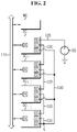
- FIG. 2 is a diagram schematically showing a signal network for setting IDs of a plurality of battery controllers according to a first embodiment of the present disclosure.
- the battery control system 100 further includes a first signal path 110, a second signal path 120 and a third signal path 130.
- Each of the plurality of battery controllers SC 1 ⁇ SC n includes a communication terminal A, an input terminal B, an output terminal C and a check terminal D.
- the communication unit 13 of the battery controller SC j may be operably coupled to the communication terminal A, the input terminal B, the output terminal C and the check terminal D of the battery controller SC j .
- the communication terminal A of the battery controller SC j is coupled to the first signal path 110.
- the battery controller SC j outputs a value indicating an ID set for the battery controller SC j to the first signal path 110.
- the battery controller SC j may output an initial value indicating that the ID was not set to the first signal path 110.
- the battery controller SC j collects data indicating the ID set for the other battery controller SC through the first signal path 110.
- the first signal path 110 serves as a communication channel for transmission and reception of ID information between the plurality of battery controllers SC 1 ⁇ SC n .
- the ID information indicates the ID allocation status of the plurality of battery controllers SC 1 ⁇ SC n .
- the ID information may include information indicating to which one of the plurality of battery controllers SC 1 ⁇ SC n the ID has been set, and information indicating the value of the ID set for each battery controller SC.
- the maximum value of the ID information collected at a specific time point being 3 indicates that the value of the ID set for the battery controller SC 1 is 1, the value of the ID set for the battery controller SC 2 is 2, the value of the ID set for the battery controller SC 3 is 3, and the IDs for the battery controller SC 4 ⁇ SC n are not yet set.
- the second signal path 120 may be a series communication channel that connects the input terminal B and the output terminal C of each of the plurality of battery controllers SC 1 ⁇ SC n from the output of the external power source 50.
- the battery controller SC a may be disposed at the upstream of the battery controller SC b
- the battery controller SC b may be disposed at the downstream of the battery controller SC a .
- the battery controller may be disposed at the upstream, and as the length of signal transmission to the external power source 50 is longer, the battery controller may be disposed at the downstream.
- the input terminal B and the output terminal C of each of the plurality of battery controllers SC 1 ⁇ SC n are coupled with a daisy chain through the second signal path 120.
- the input terminal B of the first battery controller SC 1 may be coupled to the external power source 50 by the second signal path 120.
- the high level voltage from the external power source 50 is applied to the input terminal B of the first battery controller SC 1 disposed at the most upstream through the second signal path 120.
- the output terminal C of the first battery controller SC 1 is coupled to the input terminal B of the second battery controller SC 2 by the second signal path 120.
- the input terminal B of the i th battery controller SC 1 is coupled to the output terminal C of the i-1 th battery controller SC i-1 by the second signal path 120. Accordingly, a series communication channel in which the input terminal B and the output terminal C of each of the plurality of battery controllers SC 1 ⁇ SC n are connected in a sequential order is formed from the external power source 50 to the output terminal C of the n th battery controller SC n .
- the check terminal D of the battery controller SC j is coupled to the third signal path 130.
- the third signal path 130 may be a parallel communication channel connected in common to the check terminal D of each of the plurality of battery controllers SC 1 ⁇ SC n . That is, as shown, the check terminals D of all the plurality of battery controllers SC 1 ⁇ SC n are connected in parallel by the third signal path 130.
- the output terminal C and the check terminal D of the n th battery controller SC n disposed at the most downstream are connected in common to a node N.
- the output terminal C of the n th battery controller SC n is coupled to the node N through the second signal path 120
- the check terminal D of the n th battery controller SC n is coupled to the node N through the third signal path 130. That is, the third signal path 130 may be coupled to the second signal path 120 through the node N.
- the n th battery controller SC n when the n th battery controller SC n outputs a specific voltage level (for example, the high level voltage) of signal from its output terminal C, the corresponding signal may be inputted to the check terminals D of all the plurality of battery controllers SC 1 ⁇ SC n through the third signal path 130 substantially at the same time.
- a specific voltage level for example, the high level voltage
- a terminal in 'high state H' indicates that the high level voltage is being inputted or outputted. Additionally, in the specification, a terminal in 'low state L' indicates that a low level voltage is being inputted or outputted.
- the low level voltage is the concept that is contrary to the high level voltage, and represents a voltage signal having a voltage level lower than the predetermined voltage.
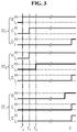
- FIG. 3 is a timing chart schematically showing the ID setting sequence using the signal network of FIG. 2 .
- all the plurality of battery controllers SC 1 ⁇ SC n may be in an ID setting standby state.
- the ID setting standby state indicates that all of the input terminal B, the output terminal C and the check terminal D of the battery controller SC j have the low state L.
- the input terminal B of the first battery controller SC 1 is shifted from the low state L to the high state H by the high level voltage from the external power source 50.
- the first battery controller SC 1 sets its ID in response to the input terminal B of the first battery controller SC 1 being the high state H. Before the time point T 0 , an ID is set for none of the plurality of battery controllers SC 1 ⁇ SC n .That is, the maximum value of the ID information collected through the first signal path 110 before the time point T 0 is equal to the initial value. Assume that the initial value is 0.
- the first battery controller SC sets 1, which is the sum of the initial value of 0 and a predetermined increment of 1, as its ID, and transmits data indicating the set ID to the first signal path 110 at least one time after the time point To.
- the ID of the first battery controller SC 1 was set based on the ID information collected by the battery controller SC 2 -SC n disposed at the downstream of the first battery controller SC 1 through the first signal path 110. Subsequently, at time point T 1 , the first battery controller SC 1 may output the high level voltage from the output terminal C of the first battery controller SC 1 .
- the input terminal B of the second battery controller SC 2 is shifted from the low state L to the high state H by the high level voltage from the output terminal C of the first battery controller SC 1 .
- the second battery controller SC 2 sets its ID in response to the input terminal B of the second battery controller SC 2 being the high state H.
- the maximum value of the ID information will be 1.
- the second battery controller SC 2 sets 2, which is the sum of the maximum value 1 of the ID information and the increment 1, as its ID, and transmits data indicating the set ID to the first signal path 110 at least one time.
- the second battery controller SC 2 may output the high level voltage from the output terminal C of the second battery controller SC 2 .
- each battery controller may periodically or aperiodically output data indicating the ID to the first signal path 110 multiple times until the ID setting sequence is completed for all the plurality of battery controllers SC 1 ⁇ SC n .
- the ID of each battery controller SC has been described as being set in ascending order by the increment from 1.
- the initial value and the increment may be values other than 0 and 1, respectively.
- the n th battery controller SC n may output the high level voltage from its output terminal C.
- the high level voltage outputted from the output terminal C of the n th battery controller SC n is applied to the third signal path 130 electrically coupled to the output terminal C of the n th battery controller SC n through the node N. Accordingly, the check terminals D of all the plurality of battery controllers SC 1 ⁇ SC n are shifted from the low state L to the high state H.
- the battery controller SC j may transmit a response signal indicating that the ID setting of the battery controller SC j is completed to the first signal path 110, and shift its output terminal C from the high state H to the low state L. Accordingly, it is possible to save the power unnecessarily consumed to keep the output terminal C in the high state H, and remove the risk of an electrical circuit of other electrical component in the battery pack BP.
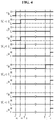
- FIG. 4 is a timing chart referenced in describing the detection of an error situation in progress of the ID setting sequence using the signal network of FIG. 2 .
- a process from time point T 10 to time point T 12 is the same as the process from the time point To to the time point T 2 shown in FIG. 3 , and repetitive descriptions are omitted herein.
- the ID setting procedure for the j th battery controller SC j starts.
- the check terminals D of all the plurality of battery controllers SC 1 ⁇ SC n have been unintentionally shifted from the low state L to the high state H. This indicates that any defect occurs in the time point Tx.
- the third signal path 130 is electrically shorted directly to the external power source 50 at the time point Tx, the situation of FIG. 3 may occur.
- the situation of FIG. 3 may occur.
- the j th battery controller SC j may output an error message from its communication terminal A.
- the j th battery controller SC j may output an error message from its communication terminal A.
- each of the plurality of battery controllers SC 1 ⁇ SC n may perform an error removal operation in response to the received error message.
- the error removal operation may include, for example, initiating the ID already set or resetting the communication unit 13.
- the upper level controller MC may disallow the turn-on of the relay 20 in response to the received error message.
- each of the plurality of battery controllers SC 1 ⁇ SC n may output an error removal message through the first signal path 110 in response to both the output terminal C and the check terminal D having the low state L.
- the error removal message indicates that the error situation was resolved by the error removal operation.
- the upper level controller MC may allow the turn-on of the relay 20.
- FIG. 5 is a diagram schematically showing a signal network for setting IDs of a plurality of battery controllers according to a second embodiment of the present disclosure.
- the second embodiment of FIG. 5 is different from the first embodiment of FIG. 2 in that the battery control system 100 further includes a sequence termination circuit 200. Accordingly, in describing the second embodiment, repetitive descriptions in common with the first embodiment are omitted herein.
- the sequence termination circuit 200 includes a resistor R and a switch SW 1 .
- a series circuit of the resistor R and the switch SW 1 is electrically coupled between the output of the external power source 50 and the ground.
- the input terminal B of the first battery controller SC 1 is connected to the external power source 50 through the resistor R. That is, the input terminal B of the first battery controller SC 1 is coupled to a connection point of the resistor R and the switch SW 1 .
- an N-channel MOSFET is used as the switch SW 1 .
- the drain and source of the N channel MOSFET are electrically coupled to the resistor R and the ground respectively.
- the gate of the N-channel MOSFET is electrically coupled to the third signal path 130.
- the sequence termination circuit 200 may further include an RC circuit 210.
- the RC circuit 210 may be a parallel circuit of a resistor and a capacitor, and protects the switch SW 1 by suppressing a rapid voltage change in gate-source voltage of the switch SW 1 .
- the third signal path 130 has the high level voltage as described above.
- the switch SW 1 is turned off in response to the third signal path 130 having the low level voltage.
- the switch SW 1 is turned on in response to the third signal path 130 having the high level voltage.
- a current path is formed between the resistor R and the ground, and the input terminal B of the first battery controller SC 1 is shifted from the high state H to the low state L. That is, the high level voltage from the external power source 50 is shut off from the input terminal B of the first battery controller SC 1 . Accordingly, compared to when the ID setting sequence was normally completed but the input terminal B of the first battery controller SC 1 is kept in the high state H by the external power source 50, it is possible to reduce the risk of an electrical short with other electrical component.
- FIG. 6 is a diagram schematically showing a signal network for setting IDs of a plurality of battery controllers according to a third embodiment of the present disclosure.
- the third embodiment of FIG. 6 is different from the first embodiment of FIG. 2 in that the battery control system 100 further includes a switch SW 2 . Accordingly, in describing the third embodiment, repetitive descriptions in common with the first embodiment are omitted herein.
- the switch SW 2 is coupled between the external power source 50 and the input terminal B of the first battery controller SC 1 .
- a P-channel MOSFET is used as the switch SW 2 .
- the drain and source of the P-channel MOSFET are electrically coupled to the input terminal B of the first battery controller SC and the output of the external power source 50 respectively.
- the gate of the P-channel MOSFET is electrically coupled to the third signal path 130.
- the switch SW 2 is turned on in response to the third signal path 130 having the low level voltage. Accordingly, while the output terminal C of the n th battery controller SC n is kept in the low state L, the input terminal B of the first battery controller SC 1 is kept in the high state H by the external power source 50.
- the switch SW 2 is turned off in response to the third signal path 130 having the high level voltage.
- the switch SW 2 is turned off, the input terminal B of the first battery controller SC 1 is shifted from the high state H to the low state L. That is, the high level voltage from the external power source 50 is shut off from the input terminal B of the first battery controller SC 1 . Accordingly, compared to when the ID setting sequence was normally completed but the input terminal B of the first battery controller SC 1 is kept in the high state H, it is possible to reduce the risk of an electrical short with other electrical component.
- FIG. 7 is a flowchart schematically showing a control method for setting an ID of a battery controller.
- the method of FIG. 7 may start when the input terminal B of the j th battery controller SC j whose ID is not set is shifted from low to high level.
- the method of FIG. 7 relates to the ID setting sequence of the j th battery controller SC j , and is equally applied to each of the plurality of battery controllers SC 1 ⁇ SC n .
- step S710 the j th battery controller SC j collects ID information indicating the ID allocation status of the plurality of battery controllers SC 1 ⁇ SC n through the first signal path 110.
- step S720 the j th battery controller SC j sets an ID of the j th battery controller SC j based on the ID information.
- the j th battery controller SC j may output data indicating the ID set for the j th battery controller SC j to the first signal path 110.
- step S730 the j th battery controller SC j outputs a high level voltage to the second signal path 120. That is, the j th battery controller SC j shifts the output terminal C of the j th battery controller SC j from the low state L to the high state H.
- step S740 the j th battery controller SC j determines whether the high level voltage from the third signal path 130 was inputted to the check terminal D of the j th battery controller SC j . That is, the j th battery controller SC j determines whether the check terminal D of the j th battery controller SC j was shifted from the low state L to the high state H.
- step S750 is performed.
- the j th battery controller SC j may output an error message.
- step S750 the j th battery controller SC j outputs a response signal indicating the completion of the ID setting sequence of the j th battery controller SC j to the first signal path 110.
- the response signal may include a value of the ID set to the j th battery controller SC j .
- the response signal outputted by each battery controller is inputted to the upper level controller MC or the battery controller (for example, SC 1 ) in charge of the function (position) of the upper level controller MC through the first signal path 110.
- the upper level controller MC or the battery controller (for example, SC 1 ) in charge of the function (position) of the upper level controller MC may determine that the ID setting has been normally completed for all the plurality of battery controllers SC 1 ⁇ SC n , and otherwise, may output the error message to the first signal path 110.
- the number of times the response signal has been received may be the total number of response signals sequentially outputted to the first signal path 110 for the period during which a predetermined standby time has passed since the start of the ID setting sequence.
- the upper level controller MC or the battery controller (for example, SC 1 ) in charge of the function (position) of the upper level controller MC may control the plurality of battery controllers SC 1 ⁇ SC n using each ID.
- FIG. 8 is a flowchart schematically showing another control method for setting an ID of a battery controller.
- the method of FIG. 8 may start when the input terminal B of the j th battery controller SC whose ID is not set is shifted from low to high level.
- the method of FIG. 8 relates to the ID setting sequence of the j th battery controller SC j , and is equally applied to each of the plurality of battery controllers SC 1 ⁇ SC n .
- step S800 the j th battery controller SC j determines whether at least one of the output terminal C or the check terminal D of the j th battery controller SC j is in the high state H.
- step S810 is performed.
- step S860 is performed.
- step S810 the j th battery controller SC j collects ID information indicating the ID allocation status of the plurality of battery controllers SC 1 ⁇ SC n through the first signal path 110.
- step S820 the j th battery controller SC j sets an ID of the j th battery controller SC j based on the ID information.
- the j th battery controller SC j may output data indicating the ID set for the j th battery controller SC j to the first signal channel at least one time.
- step S822 the j th battery controller SC j determines whether the check terminal D of the j th battery controller SC j is in the high state H.
- step S860 is performed.
- step S830 is performed.
- step S830 the j th battery controller SC j outputs a high level voltage to the second signal path 120. That is, the j th battery controller SC j shifts the output terminal C of the j th battery controller S j C from the low state L to the high state H.
- step S840 the j th battery controller SC j determines whether the high level voltage from the third signal path 130 was inputted to the check terminal D of the j th battery controller SC j . That is, the j th battery controller SC determines whether the check terminal D of the j th battery controller SC was shifted from the low state L to the high state H.
- step S850 is performed.
- step S860 may be performed.
- step S850 the j th battery controller SC j outputs a response signal indicating the completion of the ID setting sequence of the j th battery controller SC j to the first signal path 110.
- step S860 the j th battery controller SC j outputs an error message to the first signal path 110.
Landscapes
- Engineering & Computer Science (AREA)
- Power Engineering (AREA)
- Transportation (AREA)
- Mechanical Engineering (AREA)
- Life Sciences & Earth Sciences (AREA)
- Sustainable Development (AREA)
- Sustainable Energy (AREA)
- General Physics & Mathematics (AREA)
- Physics & Mathematics (AREA)
- Manufacturing & Machinery (AREA)
- Chemical & Material Sciences (AREA)
- Chemical Kinetics & Catalysis (AREA)
- Electrochemistry (AREA)
- General Chemical & Material Sciences (AREA)
- Charge And Discharge Circuits For Batteries Or The Like (AREA)
- Secondary Cells (AREA)
- Electric Propulsion And Braking For Vehicles (AREA)
Abstract
Description
- The present disclosure relates to technology that allocates IDs to a plurality of battery controllers of a battery control system in a sequential order.
- The present application claims the benefit of
Korean Patent Application No. 10-2020-0017878 filed on February 13, 2020 - Recently, there has been a rapid increase in the demand for portable electronic products such as laptop computers, video cameras and mobile phones, and with the extensive development of electric vehicles, accumulators for energy storage, robots and satellites, many studies are being made on high performance batteries that can be recharged repeatedly.
- Currently, commercially available batteries include nickel-cadmium batteries, nickel-hydrogen batteries, nickel-zinc batteries, lithium batteries and the like, and among them, lithium batteries have little or no memory effect, and thus they are gaining more attention than nickel-based batteries for their advantages that recharging can be done whenever it is convenient, the self-discharge rate is very low and the energy density is high.
- A battery pack for devices requiring high capacity and high voltage such as electric vehicles generally includes a plurality of battery modules connected in series.
- A battery control system having a multi slave system is disclosed to efficiently manage the plurality of battery modules. The battery control system includes a plurality of battery controllers provided in a one-to-one relationship with the plurality of battery modules to monitor and control the state of the plurality of battery modules. The plurality of battery controllers may be all managed by one of them or a separate upper level controller. For smooth transmission and reception of data between the plurality of battery controllers and/or between the plurality of battery controllers and the upper level controller, it is necessary to set an ID as a unique identifier for each battery controller.
-
Patent Literature 1 discloses wherein a master as the upper level controller allocates IDs to a plurality of slaves as battery controllers in a sequential order. However, the ID allocation according toPatent Literature 1 needs the master, making the process complicated, and involves detecting a potential difference between the electrode (positive or negative) of each of the plurality of batteries and the ground. - (Patent Literature 1)
Korean Patent Publication No. 10-2011-0013747 (Publication Date: February 10, 2011 - The present disclosure is designed to solve the above-described problem, and therefore the present disclosure is directed to providing a battery control system in which IDs are sequentially allocated to a plurality of battery controllers in the order in which the battery controllers are connected to one another without intervention of an upper level controller, a battery pack, an electric vehicle and an ID setting method for the battery control system.
- These and other objects and advantages of the present disclosure may be understood by the following description and will be apparent from the embodiments of the present disclosure. In addition, it will be readily understood that the objects and advantages of the present disclosure may be realized by the means set forth in the appended claims and a combination thereof.
- A battery control system according to an aspect of the present disclosure includes first to third signal paths, and first to nth battery controllers interconnected through the first to third signal paths. n is a natural number of 2 or greater. When a high level voltage as a command to start an ID setting sequence is inputted to the first battery controller through the second signal path, the first battery controller is configured to collect ID information indicating an ID allocation status of the first to nth battery controllers through the first signal path, set an ID of the first battery controller based on the ID information, and output the high level voltage to the second battery controller through the second signal path. When the high level voltage outputted by the i-1th battery controller is inputted to the ith battery controller through the second signal path, the ith battery controller is configured to collect the ID information through the first signal path, set an ID of the ith battery controller based on the ID information collected by the ith battery controller, and output the high level voltage to the second signal path. i is a natural number of 2~n. The high level voltage outputted to the second signal path by the nth battery controller is inputted to all the first to nth battery controllers through the third signal path. Each battery controller is configured to output a response signal indicating completion of the ID setting sequence to the first signal path when the high level voltage is inputted through the third signal path.
- Each battery controller includes a communication terminal, an input terminal, an output terminal and a check terminal. The communication terminal of each battery controller is coupled to the first signal path to collect the ID information. The input terminal of the first battery controller is coupled to an external power source through the second signal path, wherein the external power source outputs the high level voltage. The input terminal of the ith battery controller is coupled to the output terminal of the i-1th battery controller through the second signal path, wherein the high level voltage is outputted from the output terminal of the i-1th battery controller. The check terminal of each battery controller is coupled to the output terminal of the nth battery controller through the third signal path.
- The jth battery controller may be configured to output an error message from the communication terminal of the jth battery controller when the high level voltage is inputted to the check terminal of the jth battery controller before the high level voltage is outputted from the output terminal of the jth battery controller. j is a natural number of n or smaller.
- The jth battery controller may be configured to set the ID of the jth battery controller being equal to a sum of a maximum value of the ID information collected by the jth battery controller and a predetermined increment. j is a natural number of n or smaller.
- When the ID of the jth battery controller is set, the jth battery controller may be configured to output the ID set for the jth battery controller through the communication terminal at least one time while the high level voltage is inputted to the input terminal of the jth battery controller. j is a natural number of n or smaller.
- When the ID of the jth battery controller is set, the jth battery controller may be configured to output the high level voltage from the output terminal of the jth battery controller while the high level voltage is inputted to the input terminal of the jth battery controller. j is a natural number of n or smaller.
- The jth battery controller may be configured to terminate the ID setting sequence in response to the high level voltage being inputted to the check terminal of the jth battery controller while the high level voltage is outputted from the output terminal of the jth battery controller. j is a natural number of n or smaller.
- The battery control system may further include a sequence termination circuit including a resistor coupled between the input terminal of the first battery controller and the external power source; and a first switch electrically coupled between the resistor and a ground. The first switch may be turned on in response to the high level voltage outputted to the third signal path. When the first switch is turned on, the high level voltage from the external power source may be shut off from the input terminal of the first battery controller.
- The battery control system may further include a second switch coupled between the input terminal of the first battery controller and the external power source. The second switch is turned off in response to the high level voltage outputted to the third signal path. When the second switch is turned off, the high level voltage from the external power source may be shut off from the input terminal of the first battery controller.
- A battery pack according to another aspect of the present disclosure includes the battery control system.
- An electric vehicle according to still another aspect of the present disclosure includes the battery pack.
- An ID setting method for the battery control system according to yet another aspect of the present disclosure includes collecting, by the jth battery controller, the ID information indicating the ID allocation status of the first to nth battery controllers through the first signal path when the high level voltage is inputted to the jth battery controller through the second signal path, setting, by the jth battery controller, the ID of the jth battery controller based on the ID information, outputting, by the jth battery controller, the high level voltage to the second signal path after the ID setting of the jth battery controller is completed, and outputting, by the jth battery controller, the response signal indicating completion of the ID setting sequence of the jth battery controller to the first signal path when the high level voltage is inputted to the jth battery controller through the third signal path after the high level voltage is outputted to the second signal path by the jth battery controller.
- According to at least one of the embodiments of the present disclosure, IDs may be sequentially allocated to a plurality of battery controllers in the order in which the battery controllers are connected to one another without intervention of an upper level controller.
- According to at least one of the embodiments of the present disclosure, at least one of the plurality of battery controllers may detect an error situation in progress of the
- ID setting sequence, and automatically share the error situation with the remaining battery controllers.
- The effects of the present disclosure are not limited to the effects mentioned above, and these and other effects will be clearly understood by those skilled in the art from the appended claims.
- The accompanying drawings illustrate a preferred embodiment of the present disclosure, and together with the detailed description of the present disclosure described below, serve to provide a further understanding of the technical aspects of the present disclosure, and thus the present disclosure should not be construed as being limited to the drawings.
-
FIG. 1 is a diagram exemplarily showing a configuration of an electric vehicle according to the present disclosure. -
FIG. 2 is a diagram schematically showing a signal network for setting IDs of a plurality of battery controllers according to a first embodiment of the present disclosure. -
FIG. 3 is a timing chart schematically showing an ID setting sequence using the signal network ofFIG. 2 . -
FIG. 4 is a timing chart referenced in describing the detection of an error situation in progress of an ID setting sequence using the signal network ofFIG. 2 . -
FIG. 5 is a diagram schematically showing a signal network for setting IDs of a plurality of battery controllers according to a second embodiment of the present disclosure. -
FIG. 6 is a diagram schematically showing a signal network for setting IDs of a plurality of battery controllers according to a third embodiment of the present disclosure. -
FIG. 7 is a flowchart schematically showing a control method for setting an ID of a battery controller. -
FIG. 8 is a flowchart schematically showing another control method for setting an ID of a battery controller. - Hereinafter, the preferred embodiments of the present disclosure will be described in detail with reference to the accompanying drawings. Prior to the description, it should be understood that the terms or words used in the specification and the appended claims should not be construed as being limited to general and dictionary meanings, but rather interpreted based on the meanings and concepts corresponding to the technical aspects of the present disclosure on the basis of the principle that the inventor is allowed to define the terms appropriately for the best explanation.
- Therefore, the embodiments described herein and illustrations shown in the drawings are just a most preferred embodiment of the present disclosure, but not intended to fully describe the technical aspects of the present disclosure, so it should be understood that a variety of other equivalents and modifications could have been made thereto at the time that the application was filed.
- The terms including the ordinal number such as "first", "second" and the like, are used to distinguish one element from another among various elements, but not intended to limit the elements by the terms.
- Unless the context clearly indicates otherwise, it will be understood that the term "comprises" when used in this specification, specifies the presence of stated elements, but does not preclude the presence or addition of one or more other elements. Additionally, the term "control unit" as used herein refers to a processing unit of at least one function or operation, and this may be implemented by hardware and software either alone or in combination.
- In addition, throughout the specification, it will be further understood that when an element is referred to as being "connected to" another element, it can be directly connected to the other element or intervening elements may be present.
-
FIG. 1 is a diagram exemplarily showing a configuration of an electric vehicle according to the present disclosure. - Referring to
FIG. 1 , theelectric vehicle 1 includes a battery pack BP, arelay 20, aninverter 30, anelectric motor 40 and anexternal power source 50. - The battery pack BP may supply power required to drive the
electric motor 40 of theelectric vehicle 1. The battery pack BP includes a plurality of battery modules BM1~BMn. In the specification, the subscript symbol n used as the reference symbol is a natural number of 2 or greater, and the symbol j is a natural number of n or smaller. The plurality of battery modules BM1~BMn is connected in series and/or in parallel. Each of the plurality of battery modules BM1~BMn includes at least one battery cell BC. The battery cell BC may be a lithium ion battery cell BC. The battery cell BC is not limited to a particular type and may include any type of battery cell that can be repeated recharged. - The
relay 20 is installed on a power line PL connecting the battery pack BP to theinverter 30. Therelay 20 is controlled to be turned on/off in response to a switching signal from abattery control system 100. - The
inverter 30 is provided to convert the direct current from the battery pack BP to an alternating current in response to a control signal from thebattery control system 100 while therelay 20 is in a turn-on state. Theelectric motor 40 is a 3-phase alternating motor, and works by the alternating current power generated by theinverter 30. - The
external power source 50 is installed in theelectric vehicle 1 to supply electrical energy required for the operation of a peripheral device (not shown) installed in theelectric vehicle 1. For example, theexternal power source 50 may include a lead storage battery. The peripheral device may include a heater, an air conditioner, a lighting or the like. - The battery pack BP further includes the
battery control system 100. - The
battery control system 100 includes a plurality of battery controllers SC1~SCn. Thebattery control system 100 may further include an upper level controller MC. - The plurality of battery controllers SC1~SCn is provided in a one-to-one relationship with the plurality of battery modules BM1~BMn. The following description of the battery controller SCj is common to the plurality of battery controllers SC1~SCn respectively.
- The battery controller SCj is configured to monitor a state (for example, voltage, current, temperature, State of Charge, State of Health) of the battery module BMj. The battery controller SCj may include a
sensing unit 11, acontrol unit 12 and acommunication unit 13. - The
sensing unit 11 may include at least one of a voltage detection circuit, a current detection circuit and a temperature detection circuit. The voltage detection circuit may measure a voltage across each battery cell BC included in the battery module BMj and output a signal indicating the measured voltage of each battery cell BC to thecontrol unit 12. The current detection circuit may detect a current flowing through the battery module BMj, and output a signal indicating the detected current to thecontrol unit 12. The temperature detection circuit may detect a temperature of the battery module BMj, and output a signal indicating the detected temperature to thecontrol unit 12. - The
control unit 12 may be implemented in hardware using at least one of application specific integrated circuits (ASICs), digital signal processors (DSPs), digital signal processing devices (DSPDs), programmable logic devices (PLDs), field programmable gate arrays (FPGAs), microprocessors or electrical units for performing other functions. Thecontrol unit 12 may have memory embedded therein. The memory may store programs and data necessary to perform methods as described below. The memory may include, for example, at least one type of storage medium of flash memory type, hard disk type, Solid State Disk (SSD) type, Silicon Disk Drive (SDD) type, multimedia card micro type, random access memory (RAM), static random access memory (SRAM), read-only memory (ROM), electrically erasable programmable read-only memory (EEPROM) or programmable read-only memory (PROM). Thecontrol unit 12 may generate battery information indicating the state of the battery module BMj based on the signals from thesensing unit 11, and store the generated battery information in the memory. - The
communication unit 13 is operably coupled to thecontrol unit 12, and transmits the battery information from thecontrol unit 12 to the upper level controller MC and/or the other battery controller SC. The operably coupled refers to connection between two elements to transmit and receive a signal in one or two directions. - The power required for the operation of the battery controller SCj may be supplied from the battery module BMj and/or the
external power source 50. Before an ID setting sequence as described below is executed, the battery controller SCj may have an arbitrary identifier set to a predetermined initial value (for example, 0). - The
external power source 50 provides a high level voltage (for example, 12V) as a signal for commanding to start the ID setting sequence for the plurality of battery controllers SC1~SCn.In the specification, the high level voltage represents a voltage signal of a predetermined voltage (for example, 3V) or above. Accordingly, when the battery pack BP is installed in theelectric vehicle 1 and thebattery control system 100 is electrically coupled to theexternal power source 50, the ID setting sequence for the plurality of battery controllers SC1~SCn may automatically start. - The upper level controller MC is configured to manage all the plurality of battery modules BM1~BMn using the plurality of battery controllers SC1~SCn.The upper level controller MC may communicate with the battery controller SCj via a wired network such as local area network (LAN), controller area network (CAN) and/or a wireless network such as Bluetooth, Zigbee and WiFi. After the ID setting has been normally completed for the plurality of battery controllers SC1~SCn, the upper level controller MC controls the charge/discharge of the plurality of battery modules BM1~BMn based on the battery information from the plurality of battery controllers SC1~SCn.For example, when the battery information from the battery controller SCj indicates an abnormal condition (for example, overvoltage, overdischarge, overheat) of at least one battery cell BC in the battery module BMj, the upper level controller MC may turn off the
relay 20 to protect the battery module BMj. The hardware configuration of the upper level controller MC may be the same as that of the battery controller SCj except that thesensing unit 11 may be omitted. - Alternatively, the upper level controller MC is omitted from the
battery control system 100, and instead, one (for example, SC1) of the plurality of battery controllers SC1~SCn may take charge of the function (position) of the upper level controller MC. In this case, the battery controller (for example, SC1) in charge of the function of the upper level controller MC may be referred to as 'master', and each of the remaining battery controllers SC may be referred to as 'slave'. -
FIG. 2 is a diagram schematically showing a signal network for setting IDs of a plurality of battery controllers according to a first embodiment of the present disclosure. - Referring to
FIGS. 1 and2 , thebattery control system 100 further includes afirst signal path 110, asecond signal path 120 and athird signal path 130. Each of the plurality of battery controllers SC1~SCn includes a communication terminal A, an input terminal B, an output terminal C and a check terminal D. Thecommunication unit 13 of the battery controller SCj may be operably coupled to the communication terminal A, the input terminal B, the output terminal C and the check terminal D of the battery controller SCj. - The communication terminal A of the battery controller SCj is coupled to the
first signal path 110. The battery controller SCj outputs a value indicating an ID set for the battery controller SCj to thefirst signal path 110. When the ID is not yet set for the battery controller SCj, the battery controller SCj may output an initial value indicating that the ID was not set to thefirst signal path 110. The battery controller SCj collects data indicating the ID set for the other battery controller SC through thefirst signal path 110. That is, thefirst signal path 110 serves as a communication channel for transmission and reception of ID information between the plurality of battery controllers SC1~SCn.The ID information indicates the ID allocation status of the plurality of battery controllers SC1~SCn.The ID information may include information indicating to which one of the plurality of battery controllers SC1~SCn the ID has been set, and information indicating the value of the ID set for each battery controller SC. For example, in case that the value of the ID is sequentially set for the plurality of battery controllers SC1~SCn in an ascending order of from 1 to n, the maximum value of the ID information collected at a specific time point being 3 indicates that the value of the ID set for the battery controller SC1 is 1, the value of the ID set for the battery controller SC2 is 2, the value of the ID set for the battery controller SC3 is 3, and the IDs for the battery controller SC4~SCn are not yet set. - The
second signal path 120 may be a series communication channel that connects the input terminal B and the output terminal C of each of the plurality of battery controllers SC1~SCn from the output of theexternal power source 50. In the specification, where n ≥ b > a > 0 (each of a and b is a natural number), the battery controller SCa may be disposed at the upstream of the battery controller SCb, and the battery controller SCb may be disposed at the downstream of the battery controller SCa. That is, in the series signal channel by thesecond signal path 120, as the length of signal transmission to theexternal power source 50 is shorter, the battery controller may be disposed at the upstream, and as the length of signal transmission to theexternal power source 50 is longer, the battery controller may be disposed at the downstream. - The input terminal B and the output terminal C of each of the plurality of battery controllers SC1~SCn are coupled with a daisy chain through the
second signal path 120. In detail, the input terminal B of the first battery controller SC1 may be coupled to theexternal power source 50 by thesecond signal path 120. In case that the battery pack BP is installed in theelectric vehicle 1, the high level voltage from theexternal power source 50 is applied to the input terminal B of the first battery controller SC1 disposed at the most upstream through thesecond signal path 120. The output terminal C of the first battery controller SC1 is coupled to the input terminal B of the second battery controller SC2 by thesecond signal path 120. When i is a natural number of 2~n, the input terminal B of the ith battery controller SC1 is coupled to the output terminal C of the i-1th battery controller SCi-1 by thesecond signal path 120. Accordingly, a series communication channel in which the input terminal B and the output terminal C of each of the plurality of battery controllers SC1~SCn are connected in a sequential order is formed from theexternal power source 50 to the output terminal C of the nth battery controller SCn. - The check terminal D of the battery controller SCj is coupled to the
third signal path 130. Thethird signal path 130 may be a parallel communication channel connected in common to the check terminal D of each of the plurality of battery controllers SC1~SCn. That is, as shown, the check terminals D of all the plurality of battery controllers SC1~SCn are connected in parallel by thethird signal path 130. - The output terminal C and the check terminal D of the nth battery controller SCn disposed at the most downstream are connected in common to a node N. Referring to
FIG. 2 , the output terminal C of the nth battery controller SCn is coupled to the node N through thesecond signal path 120, and the check terminal D of the nth battery controller SCn is coupled to the node N through thethird signal path 130. That is, thethird signal path 130 may be coupled to thesecond signal path 120 through the node N. Accordingly, when the nth battery controller SCn outputs a specific voltage level (for example, the high level voltage) of signal from its output terminal C, the corresponding signal may be inputted to the check terminals D of all the plurality of battery controllers SC1~SCn through thethird signal path 130 substantially at the same time. - In the specification, a terminal in 'high state H' indicates that the high level voltage is being inputted or outputted. Additionally, in the specification, a terminal in 'low state L' indicates that a low level voltage is being inputted or outputted. In the specification, the low level voltage is the concept that is contrary to the high level voltage, and represents a voltage signal having a voltage level lower than the predetermined voltage.
-
FIG. 3 is a timing chart schematically showing the ID setting sequence using the signal network ofFIG. 2 . Before thebattery control system 100 is coupled to theexternal power source 50, all the plurality of battery controllers SC1~SCn may be in an ID setting standby state. The ID setting standby state indicates that all of the input terminal B, the output terminal C and the check terminal D of the battery controller SCj have the low state L. - Referring to
FIGS. 1 to 3 , at time point T0, the input terminal B of the first battery controller SC1 is shifted from the low state L to the high state H by the high level voltage from theexternal power source 50. - The first battery controller SC1 sets its ID in response to the input terminal B of the first battery controller SC1 being the high state H. Before the time point T0, an ID is set for none of the plurality of battery controllers SC1~SCn.That is, the maximum value of the ID information collected through the
first signal path 110 before the time point T0 is equal to the initial value. Assume that the initial value is 0. The first battery controller SC sets 1, which is the sum of the initial value of 0 and a predetermined increment of 1, as its ID, and transmits data indicating the set ID to thefirst signal path 110 at least one time after the time point To. Accordingly, it may be determined that the ID of the first battery controller SC1 was set based on the ID information collected by the battery controller SC2-SCn disposed at the downstream of the first battery controller SC1 through thefirst signal path 110. Subsequently, at time point T1, the first battery controller SC1 may output the high level voltage from the output terminal C of the first battery controller SC1. - At the time point T1, the input terminal B of the second battery controller SC2 is shifted from the low state L to the high state H by the high level voltage from the output terminal C of the first battery controller SC1. The second battery controller SC2 sets its ID in response to the input terminal B of the second battery controller SC2 being the high state H. As only the ID of the first battery controller SC1 was set until the time point T1, the maximum value of the ID information will be 1. The second battery controller SC2 sets 2, which is the sum of the
maximum value 1 of the ID information and theincrement 1, as its ID, and transmits data indicating the set ID to thefirst signal path 110 at least one time. Accordingly, it may be determined that the ID of the second battery controller SC2 was set based on the ID information collected by the battery controller SC3~SCn disposed at the downstream of the second battery controller SC2 through thefirst signal path 110. Subsequently, at time point T2, the second battery controller SC2 may output the high level voltage from the output terminal C of the second battery controller SC2. - The above-described process is repeated until the ID of the nth battery controller SCn disposed at the most downstream is set. When the ID is set for each battery controller, each battery controller may periodically or aperiodically output data indicating the ID to the
first signal path 110 multiple times until the ID setting sequence is completed for all the plurality of battery controllers SC1~SCn. - In the ID setting sequence according to
FIG. 2 , in the ID setting from the first battery controller SC1 to the nth battery controller SCn, the ID of each battery controller SC has been described as being set in ascending order by the increment from 1. However, this is provided for illustration, and the scope of the present disclosure is not limited thereto. Further, the initial value and the increment may be values other than 0 and 1, respectively. - At time point Tn after the ID of the nth battery controller SCn is set, the nth battery controller SCn may output the high level voltage from its output terminal C.
- At the time point Tn, the high level voltage outputted from the output terminal C of the nth battery controller SCn is applied to the
third signal path 130 electrically coupled to the output terminal C of the nth battery controller SCn through the node N. Accordingly, the check terminals D of all the plurality of battery controllers SC1~SCn are shifted from the low state L to the high state H. - In response to its check terminal D being the high state H, the battery controller SCj may transmit a response signal indicating that the ID setting of the battery controller SCj is completed to the
first signal path 110, and shift its output terminal C from the high state H to the low state L. Accordingly, it is possible to save the power unnecessarily consumed to keep the output terminal C in the high state H, and remove the risk of an electrical circuit of other electrical component in the battery pack BP. -
FIG. 4 is a timing chart referenced in describing the detection of an error situation in progress of the ID setting sequence using the signal network ofFIG. 2 . - In
FIG. 4 , a process from time point T10 to time point T12 is the same as the process from the time point To to the time point T2 shown inFIG. 3 , and repetitive descriptions are omitted herein. - Referring to
FIG. 4 , at time point T1j, when the input terminal B of the jth battery controller SCj is shifted from the low state L to the high state H, the ID setting procedure for the jth battery controller SCj starts. In this instance, at time point Tx of the period during which the output terminal C of the jth battery controller SCj is kept in the low state L, the check terminals D of all the plurality of battery controllers SC1~SCn have been unintentionally shifted from the low state L to the high state H. This indicates that any defect occurs in the time point Tx. In an example, when thethird signal path 130 is electrically shorted directly to theexternal power source 50 at the time point Tx, the situation ofFIG. 3 may occur. In another example, when the output terminal C and/or the check terminal D of the nth battery controller SCn is shifted from the low state L to the high state H at the time point Tx due to maloperation of the nth battery controller SCn, the situation ofFIG. 3 may occur. - When the output terminal C of the jth battery controller SCj is kept in the low state L but the check terminal D of the jth battery controller SCj is shifted from the low state L to the high state H, the jth battery controller SCj may output an error message from its communication terminal A.
- When the input terminal B of the jth battery controller SCj is kept in the low state L but the output terminal C and/or the check terminal D of the jth battery controller SCj is shifted from the low state L to the high state H, the jth battery controller SCj may output an error message from its communication terminal A.
- When the error message is received through the
first signal path 110, each of the plurality of battery controllers SC1~SCn may perform an error removal operation in response to the received error message. The error removal operation may include, for example, initiating the ID already set or resetting thecommunication unit 13. When the error message is received through thefirst signal path 110, the upper level controller MC may disallow the turn-on of therelay 20 in response to the received error message. - After the error removal operation is performed, each of the plurality of battery controllers SC1~SCn may output an error removal message through the
first signal path 110 in response to both the output terminal C and the check terminal D having the low state L. The error removal message indicates that the error situation was resolved by the error removal operation. When the error removal message is received through thefirst signal path 110, the upper level controller MC may allow the turn-on of therelay 20. -
FIG. 5 is a diagram schematically showing a signal network for setting IDs of a plurality of battery controllers according to a second embodiment of the present disclosure. - The second embodiment of
FIG. 5 is different from the first embodiment ofFIG. 2 in that thebattery control system 100 further includes asequence termination circuit 200. Accordingly, in describing the second embodiment, repetitive descriptions in common with the first embodiment are omitted herein. - Referring to
FIG. 5 , thesequence termination circuit 200 includes a resistor R and a switch SW1. A series circuit of the resistor R and the switch SW1 is electrically coupled between the output of theexternal power source 50 and the ground. The input terminal B of the first battery controller SC1 is connected to theexternal power source 50 through the resistor R. That is, the input terminal B of the first battery controller SC1 is coupled to a connection point of the resistor R and the switch SW1. - In
FIG. 5 , for example, an N-channel MOSFET is used as the switch SW1. The drain and source of the N channel MOSFET are electrically coupled to the resistor R and the ground respectively. The gate of the N-channel MOSFET is electrically coupled to thethird signal path 130. Thesequence termination circuit 200 may further include anRC circuit 210. TheRC circuit 210 may be a parallel circuit of a resistor and a capacitor, and protects the switch SW1 by suppressing a rapid voltage change in gate-source voltage of the switch SW1. - When the ID setting is normally completed from the first battery controller SC1 to the nth battery controller SCn, the
third signal path 130 has the high level voltage as described above. - The switch SW1 is turned off in response to the
third signal path 130 having the low level voltage. The switch SW1 is turned on in response to thethird signal path 130 having the high level voltage. When the switch SW1 is turned on, a current path is formed between the resistor R and the ground, and the input terminal B of the first battery controller SC1 is shifted from the high state H to the low state L. That is, the high level voltage from theexternal power source 50 is shut off from the input terminal B of the first battery controller SC1. Accordingly, compared to when the ID setting sequence was normally completed but the input terminal B of the first battery controller SC1 is kept in the high state H by theexternal power source 50, it is possible to reduce the risk of an electrical short with other electrical component. -
FIG. 6 is a diagram schematically showing a signal network for setting IDs of a plurality of battery controllers according to a third embodiment of the present disclosure. - The third embodiment of
FIG. 6 is different from the first embodiment ofFIG. 2 in that thebattery control system 100 further includes a switch SW2. Accordingly, in describing the third embodiment, repetitive descriptions in common with the first embodiment are omitted herein. - The switch SW2 is coupled between the
external power source 50 and the input terminal B of the first battery controller SC1. InFIG. 6 , for example, a P-channel MOSFET is used as the switch SW2. The drain and source of the P-channel MOSFET are electrically coupled to the input terminal B of the first battery controller SC and the output of theexternal power source 50 respectively. The gate of the P-channel MOSFET is electrically coupled to thethird signal path 130. - The switch SW2 is turned on in response to the
third signal path 130 having the low level voltage. Accordingly, while the output terminal C of the nth battery controller SCn is kept in the low state L, the input terminal B of the first battery controller SC1 is kept in the high state H by theexternal power source 50. - The switch SW2 is turned off in response to the
third signal path 130 having the high level voltage. When the switch SW2 is turned off, the input terminal B of the first battery controller SC1 is shifted from the high state H to the low state L. That is, the high level voltage from theexternal power source 50 is shut off from the input terminal B of the first battery controller SC1. Accordingly, compared to when the ID setting sequence was normally completed but the input terminal B of the first battery controller SC1 is kept in the high state H, it is possible to reduce the risk of an electrical short with other electrical component. -
FIG. 7 is a flowchart schematically showing a control method for setting an ID of a battery controller. The method ofFIG. 7 may start when the input terminal B of the jth battery controller SCj whose ID is not set is shifted from low to high level. The method ofFIG. 7 relates to the ID setting sequence of the jth battery controller SCj, and is equally applied to each of the plurality of battery controllers SC1~SCn. - Referring to
FIGS. 1 to 7 , in step S710, the jth battery controller SCj collects ID information indicating the ID allocation status of the plurality of battery controllers SC1~SCn through thefirst signal path 110. - In step S720, the jth battery controller SCj sets an ID of the jth battery controller SCj based on the ID information. The jth battery controller SCj may output data indicating the ID set for the jth battery controller SCj to the
first signal path 110. - In step S730, the jth battery controller SCj outputs a high level voltage to the
second signal path 120. That is, the jth battery controller SCj shifts the output terminal C of the jth battery controller SCj from the low state L to the high state H. - In step S740, the jth battery controller SCj determines whether the high level voltage from the
third signal path 130 was inputted to the check terminal D of the jth battery controller SCj. That is, the jth battery controller SCj determines whether the check terminal D of the jth battery controller SCj was shifted from the low state L to the high state H. When a value of the step S740 is "Yes", step S750 is performed. When the check terminal D of the jth battery controller SCj is not shifted from the low state L to the high state H at the lapse of a predetermined time after the time point at which the output terminal C of the jth battery controller SCj is shifted from the low state L to the high state H, the jth battery controller SCj may output an error message. - In step S750, the jth battery controller SCj outputs a response signal indicating the completion of the ID setting sequence of the jth battery controller SCj to the
first signal path 110. The response signal may include a value of the ID set to the jth battery controller SCj. - The response signal outputted by each battery controller is inputted to the upper level controller MC or the battery controller (for example, SC1) in charge of the function (position) of the upper level controller MC through the
first signal path 110. - When the number of times the response signal has been received and/or the maximum value of the ID included in the response signal is equal to the maximum value of the ID information, the upper level controller MC or the battery controller (for example, SC1) in charge of the function (position) of the upper level controller MC may determine that the ID setting has been normally completed for all the plurality of battery controllers SC1~SCn, and otherwise, may output the error message to the
first signal path 110. The number of times the response signal has been received may be the total number of response signals sequentially outputted to thefirst signal path 110 for the period during which a predetermined standby time has passed since the start of the ID setting sequence. - When it is determined that the ID setting has been normally completed, the upper level controller MC or the battery controller (for example, SC1) in charge of the function (position) of the upper level controller MC may control the plurality of battery controllers SC1~SCn using each ID.
-
FIG. 8 is a flowchart schematically showing another control method for setting an ID of a battery controller. The method ofFIG. 8 may start when the input terminal B of the jth battery controller SC whose ID is not set is shifted from low to high level. The method ofFIG. 8 relates to the ID setting sequence of the jth battery controller SCj, and is equally applied to each of the plurality of battery controllers SC1~SCn. - Referring to
FIGS. 1 to 6 and8 , in step S800, the jth battery controller SCj determines whether at least one of the output terminal C or the check terminal D of the jth battery controller SCj is in the high state H. When a value of the step S800 is "No", step S810 is performed. When the value of the step S800 is "Yes", the step S860 is performed. - In step S810, the jth battery controller SCj collects ID information indicating the ID allocation status of the plurality of battery controllers SC1~SCn through the
first signal path 110. - In step S820, the jth battery controller SCj sets an ID of the jth battery controller SCj based on the ID information. The jth battery controller SCj may output data indicating the ID set for the jth battery controller SCj to the first signal channel at least one time.
- In step S822, the jth battery controller SCj determines whether the check terminal D of the jth battery controller SCj is in the high state H. When a value of the step S822 is "Yes", step S860 is performed. When the value of the step S822 is "No", the step S830 is performed.
- In step S830, the jth battery controller SCj outputs a high level voltage to the
second signal path 120. That is, the jth battery controller SCj shifts the output terminal C of the jth battery controller SjC from the low state L to the high state H. - In step S840, the jth battery controller SCj determines whether the high level voltage from the
third signal path 130 was inputted to the check terminal D of the jth battery controller SCj. That is, the jth battery controller SC determines whether the check terminal D of the jth battery controller SC was shifted from the low state L to the high state H. When a value of the step S840 is "Yes", step S850 is performed. When the check terminal D of the jth battery controller SCj is not shifted from the low state L to the high state H at the lapse of a predetermined time from the time point at which the output terminal C of the jth battery controller SCj is shifted from the low state L to the high state H, step S860 may be performed. - In step S850, the jth battery controller SCj outputs a response signal indicating the completion of the ID setting sequence of the jth battery controller SCj to the
first signal path 110. - In step S860, the jth battery controller SCj outputs an error message to the
first signal path 110. - The embodiments of the present disclosure described hereinabove are not implemented only through the apparatus and method, and may be implemented through programs that perform functions corresponding to the configurations of the embodiments of the present disclosure or recording media having the programs recorded thereon, and such implementation may be easily achieved by those skilled in the art from the disclosure of the embodiments previously described.
- While the present disclosure has been hereinabove described with regard to a limited number of embodiments and drawings, the present disclosure is not limited thereto and it is obvious to those skilled in the art that various modifications and changes may be made thereto within the technical aspects of the present disclosure and the equivalent scope of the appended claims.
- Additionally, as many substitutions, modifications and changes may be made to the present disclosure described hereinabove by those skilled in the art without departing from the technical aspects of the present disclosure, the present disclosure is not limited by the above-described embodiments and the accompanying drawings, and some or all of the embodiments may be selectively combined to allow various modifications.
Claims (12)
- A battery control system, comprising:first to third signal paths; andfirst to nth battery controllers interconnected through the first to third signal paths, wherein n is a natural number of 2 or greater,wherein the first battery controller is configured to:when a high level voltage as a command to start an ID setting sequence is inputted to the first battery controller through the second signal path, collect ID information indicating an ID allocation status of the first to nth battery controllers through the first signal path, set an ID of the first battery controller based on the ID information, and output the high level voltage to the second battery controller through the second signal path,the ith battery controller is configured to:when the high level voltage outputted by the i-1th battery controller is inputted to the ith battery controller through the second signal path, collect the ID information through the first signal path, set an ID of the ith battery controller based on the ID information collected by the ith battery controller, and output the high level voltage to the second signal path, wherein i is a natural number of 2~n,wherein the high level voltage outputted to the second signal path by the nth battery controller is inputted to all the first to nth battery controllers through the third signal path, andeach battery controller is configured to output a response signal indicating completion of the ID setting sequence to the first signal path when the high level voltage is inputted through the third signal path.
- The battery control system according to claim 1, wherein each battery controller includes a communication terminal, an input terminal, an output terminal and a check terminal,the communication terminal of each battery controller is coupled to the first signal path to collect the ID information,the input terminal of the first battery controller is coupled to an external power source through the second signal path, wherein the external power source outputs the high level voltage,the input terminal of the ith battery controller is coupled to the output terminal of the i-1th battery controller through the second signal path, wherein the high level voltage is outputted from the output terminal of the i-1th battery controller, andthe check terminal of each battery controller is coupled to the output terminal of the nth battery controller through the third signal path.
- The battery control system according to claim 2, wherein the jth battery controller is configured to output an error message from the communication terminal of the jth battery controller when the high level voltage is inputted to the check terminal of the jth battery controller before the high level voltage is outputted from the output terminal of the jth battery controller, and
j is a natural number of n or smaller. - The battery control system according to claim 2, wherein the jth battery controller is configured to set the ID of the jth battery controller being equal to a sum of a maximum value of the ID information collected by the jth battery controller and a predetermined increment, and
j is a natural number of n or smaller. - The battery control system according to claim 2, wherein when the ID of the jth battery controller is set, the jth battery controller is configured to output the ID set for the jth battery controller through the communication terminal at least one time while the high level voltage is inputted to the input terminal of the jth battery controller, and
j is a natural number of n or smaller. - The battery control system according to claim 2, wherein when the ID of the jth battery controller is set, the jth battery controller is configured to output the high level voltage from the output terminal of the jth battery controller while the high level voltage is inputted to the input terminal of the jth battery controller, and
j is a natural number of n or smaller. - The battery control system according to claim 2, wherein the jth battery controller is configured to terminate the ID setting sequence in response to the high level voltage being inputted to the check terminal of the jth battery controller while the high level voltage is outputted from the output terminal of the jth battery controller, and
j is a natural number of n or smaller. - The battery control system according to claim 2, further comprising:a sequence termination circuit including a resistor coupled between the input terminal of the first battery controller and the external power source; and a first switch electrically coupled between the resistor and a ground,wherein the first switch is turned on in response to the high level voltage outputted to the third signal path, andwhen the first switch is turned on, the high level voltage from the external power source is shut off from the input terminal of the first battery controller.
- The battery control system according to claim 2, further comprising:a second switch coupled between the input terminal of the first battery controller and the external power source,wherein the second switch is turned off in response to the high level voltage outputted to the third signal path, andwhen the second switch is turned off, the high level voltage from the external power source is shut off from the input terminal of the first battery controller.
- A battery pack comprising the battery control system according to any one of claims 1 to 9.
- An electric vehicle comprising the battery pack according to claim 10.
- An ID setting method for the battery control system according to any one of claims 2 to 9, comprising:collecting, by the jth battery controller, the ID information indicating the ID allocation status of the first to nth battery controllers through the first signal path when the high level voltage is inputted to the jth battery controller through the second signal path;setting, by the jth battery controller, the ID of the jth battery controller based on the ID information;outputting, by the jth battery controller, the high level voltage to the second signal path after the ID setting of the jth battery controller is completed; andoutputting, by the jth battery controller, the response signal indicating completion of the ID setting sequence of the jth battery controller to the first signal path when the high level voltage is inputted to the jth battery controller through the third signal path after the high level voltage is outputted to the second signal path by the jth battery controller.
Applications Claiming Priority (2)
| Application Number | Priority Date | Filing Date | Title |
|---|---|---|---|
| KR1020200017878A KR102861413B1 (en) | 2020-02-13 | 2020-02-13 | Battery control system, battery pack, electric vehicle, and control method for the battery control system |
| PCT/KR2021/001504 WO2021162348A1 (en) | 2020-02-13 | 2021-02-04 | Battery control system, battery pack, electrical vehicle, and id setting method for battery control system |
Publications (2)
| Publication Number | Publication Date |
|---|---|
| EP3996237A1 true EP3996237A1 (en) | 2022-05-11 |
| EP3996237A4 EP3996237A4 (en) | 2022-11-23 |
Family
ID=77292499
Family Applications (1)
| Application Number | Title | Priority Date | Filing Date |
|---|---|---|---|
| EP21754243.0A Pending EP3996237A4 (en) | 2020-02-13 | 2021-02-04 | BATTERY CONTROL SYSTEM, BATTERY PACK, ELECTRIC VEHICLE AND ID SETTING METHOD FOR BATTERY CONTROL SYSTEM |
Country Status (6)
| Country | Link |
|---|---|
| US (1) | US12049154B2 (en) |
| EP (1) | EP3996237A4 (en) |
| JP (1) | JP7207792B2 (en) |
| KR (1) | KR102861413B1 (en) |
| CN (1) | CN113924227B (en) |
| WO (1) | WO2021162348A1 (en) |
Families Citing this family (5)
| Publication number | Priority date | Publication date | Assignee | Title |
|---|---|---|---|---|
| KR102861413B1 (en) * | 2020-02-13 | 2025-09-17 | 주식회사 엘지에너지솔루션 | Battery control system, battery pack, electric vehicle, and control method for the battery control system |
| JP7211567B2 (en) * | 2020-08-21 | 2023-01-24 | 株式会社村田製作所 | storage system |
| CN121114775A (en) * | 2020-11-27 | 2025-12-12 | 株式会社Lg新能源 | Battery diagnostic devices, battery diagnostic methods, battery packs and vehicles |
| US12079150B2 (en) * | 2021-03-17 | 2024-09-03 | Tmeic Corporation | Bus connection system |
| KR102932304B1 (en) * | 2021-08-30 | 2026-02-27 | 주식회사 엘지에너지솔루션 | Battery management apparatus and operating method of the same |
Family Cites Families (48)
| Publication number | Priority date | Publication date | Assignee | Title |
|---|---|---|---|---|
| JP2005217945A (en) | 2004-01-30 | 2005-08-11 | Mitsumi Electric Co Ltd | Communication apparatus and communication method of communication system |
| WO2009076418A1 (en) | 2007-12-11 | 2009-06-18 | Antonio Trigiani | Battery management system |
| JP4796119B2 (en) | 2008-12-09 | 2011-10-19 | 三菱重工業株式会社 | Battery device |
| KR101687433B1 (en) | 2009-06-10 | 2016-12-16 | 에이일이삼 시스템즈, 엘엘씨 | System and method for communicating notice to limit degradation within a battery pack |
| KR101156342B1 (en) * | 2009-08-03 | 2012-06-13 | 삼성에스디아이 주식회사 | Battery id setting system and driving method thereof |
| US8258747B2 (en) * | 2010-05-13 | 2012-09-04 | GM Global Technology Operations LLC | Method for automatic battery controller identification and cell indexing via a multi-purpose signal line |
| JP5640474B2 (en) * | 2010-06-07 | 2014-12-17 | ソニー株式会社 | Battery system |
| US8525477B2 (en) * | 2010-07-15 | 2013-09-03 | O2Micro, Inc. | Assigning addresses to multiple cascade battery modules in electric or electric hybrid vehicles |
| KR101245279B1 (en) * | 2010-10-11 | 2013-03-19 | 주식회사 엘지화학 | Method and System for setting up sequent ID of multi-slave in battery pack |
| EP2636208A4 (en) * | 2010-11-05 | 2016-05-18 | Alelion Batteries Ab | Battery module system and method for initialising battery modules |
| JP5259752B2 (en) * | 2011-02-04 | 2013-08-07 | 株式会社日立製作所 | Vehicle travel motor control device and vehicle equipped with the same |
| JP5902149B2 (en) | 2011-03-10 | 2016-04-13 | 三洋電機株式会社 | Power supply system and identification information setting method for power supply system |
| US9446679B2 (en) * | 2011-03-28 | 2016-09-20 | Sanyo Electric Co., Ltd. | Battery system, electric vehicle, mobile unit, electric power storage device and power supply device |
| JP5561239B2 (en) | 2011-05-20 | 2014-07-30 | 三菱自動車工業株式会社 | Automatic numbering device |
| KR101386080B1 (en) * | 2011-09-05 | 2014-04-17 | 주식회사 엘지화학 | Method and system for identifier allowcation of multi-slave in battery pack |
| US8645580B2 (en) | 2011-09-06 | 2014-02-04 | Semiconductor Components Industries, Llc | Circuit and electronic module for automatic addressing |
| KR101455443B1 (en) * | 2011-09-26 | 2014-10-28 | 주식회사 엘지화학 | Method for allocating unique identifier and Battery management system using the same |
| JP2013077520A (en) | 2011-09-30 | 2013-04-25 | Toshiba Corp | Storage battery device, and method and program for controlling storage battery device |
| US9774193B2 (en) | 2011-10-26 | 2017-09-26 | Eetrex, Inc. | Battery cell charge balancing |
| KR101561885B1 (en) * | 2011-11-25 | 2015-10-21 | 주식회사 엘지화학 | System and method for identifier allowcation of multi-bms |
| KR101539689B1 (en) * | 2012-02-20 | 2015-07-27 | 주식회사 엘지화학 | System and method for identifier allowcation of multi-bms |
| CN104395770B (en) * | 2012-05-24 | 2016-12-14 | 日立汽车系统株式会社 | Battery control device |
| US8904049B2 (en) * | 2012-08-23 | 2014-12-02 | Lg Chem, Ltd. | Battery pack monitoring system and method for assigning a binary ID to a microprocessor in the battery pack monitoring system |
| KR20150054789A (en) | 2012-09-10 | 2015-05-20 | 르네사스 일렉트로닉스 가부시키가이샤 | Semiconductor device and battery voltage monitoring device |
| KR101433478B1 (en) * | 2012-12-17 | 2014-09-18 | 넥스콘 테크놀러지 주식회사 | A Method of Auto CAN ID Setting for Energy Storage System Slave Battery Management System |
| KR101768251B1 (en) | 2013-04-05 | 2017-08-30 | 삼성에스디아이 주식회사 | Battery Pack Providing Confirmation For Normal Connection Of Battery Module |
| KR102210890B1 (en) * | 2013-06-05 | 2021-02-02 | 삼성에스디아이 주식회사 | Battery management system, and method of managing the same |
| US9477616B2 (en) | 2013-08-07 | 2016-10-25 | Micron Technology, Inc. | Devices, systems, and methods of reducing chip select |
| KR101632350B1 (en) * | 2013-09-09 | 2016-06-21 | 주식회사 엘지화학 | System and method for communication identifier allowcation of multi-bms |
| JP6262475B2 (en) * | 2013-09-10 | 2018-01-17 | ローム株式会社 | Voltage detector |
| KR101754948B1 (en) * | 2014-10-07 | 2017-07-06 | 주식회사 엘지화학 | Method and System for Allocating Communication ID of Battery Management Module |
| US10794957B2 (en) * | 2015-12-17 | 2020-10-06 | Lg Chem, Ltd. | Battery module and cell configuration recognition system for ID assignment |
| CA3012430A1 (en) * | 2016-01-29 | 2017-08-03 | Nantenergy, Inc. | Automatic addressing of battery nodes in a battery system |
| KR102123671B1 (en) | 2016-02-22 | 2020-06-16 | 주식회사 엘지화학 | Method allocating identifier for battery management system |
| KR102005394B1 (en) * | 2017-03-16 | 2019-10-01 | 주식회사 엘지화학 | A method of automatically setting the communication terminal resistance of an energy storage device(ESS) |
| KR102101910B1 (en) * | 2017-03-28 | 2020-04-17 | 주식회사 엘지화학 | Method for avoiding id duplicate allocation of battery module |
| JP2018207350A (en) * | 2017-06-06 | 2018-12-27 | 株式会社デンソーテン | COMMUNICATION SYSTEM, COMMUNICATION DEVICE, AND COMMUNICATION METHOD |
| KR102173778B1 (en) * | 2017-07-25 | 2020-11-03 | 주식회사 엘지화학 | Battery management unit and a battery pack including the same |
| JP7035738B2 (en) * | 2018-04-06 | 2022-03-15 | トヨタ自動車株式会社 | Vehicles and how to charge the vehicle |
| WO2019214824A1 (en) * | 2018-05-09 | 2019-11-14 | Byton Limited | Flexibly configurable traction battery |
| KR102669130B1 (en) | 2018-08-09 | 2024-05-23 | 엘지전자 주식회사 | Laundry Treatment Apparatus) |
| KR20200031931A (en) * | 2018-09-17 | 2020-03-25 | 주식회사 엘지화학 | System and method for recognition of BMS |
| KR102258814B1 (en) * | 2018-10-04 | 2021-07-14 | 주식회사 엘지에너지솔루션 | System and method for communicating between BMS |
| KR102510886B1 (en) * | 2018-11-23 | 2023-03-16 | 삼성에스디아이 주식회사 | A slave module and a number assignment system including the slave module |
| JP7021646B2 (en) * | 2019-02-05 | 2022-02-17 | 株式会社デンソー | Battery monitoring device |
| KR102869522B1 (en) * | 2019-11-13 | 2025-10-10 | 삼성에스디아이 주식회사 | Battery system and method of allocating CAN ID |
| KR102861413B1 (en) * | 2020-02-13 | 2025-09-17 | 주식회사 엘지에너지솔루션 | Battery control system, battery pack, electric vehicle, and control method for the battery control system |
| JP7211567B2 (en) * | 2020-08-21 | 2023-01-24 | 株式会社村田製作所 | storage system |
-
2020
- 2020-02-13 KR KR1020200017878A patent/KR102861413B1/en active Active
-
2021
- 2021-02-04 EP EP21754243.0A patent/EP3996237A4/en active Pending
- 2021-02-04 US US17/615,510 patent/US12049154B2/en active Active
- 2021-02-04 CN CN202180003540.3A patent/CN113924227B/en active Active
- 2021-02-04 JP JP2021565734A patent/JP7207792B2/en active Active
- 2021-02-04 WO PCT/KR2021/001504 patent/WO2021162348A1/en not_active Ceased
Also Published As
| Publication number | Publication date |
|---|---|
| JP2022531864A (en) | 2022-07-12 |
| CN113924227A (en) | 2022-01-11 |
| CN113924227B (en) | 2023-05-30 |
| KR102861413B1 (en) | 2025-09-17 |
| EP3996237A4 (en) | 2022-11-23 |
| WO2021162348A1 (en) | 2021-08-19 |
| KR20210103299A (en) | 2021-08-23 |
| JP7207792B2 (en) | 2023-01-18 |
| US20220314832A1 (en) | 2022-10-06 |
| US12049154B2 (en) | 2024-07-30 |
Similar Documents
| Publication | Publication Date | Title |
|---|---|---|
| EP3561940B1 (en) | Master battery management unit and battery pack including same | |
| US11718188B2 (en) | Wireless battery management system and battery pack including same | |
| EP3557687B1 (en) | Battery management unit and battery pack including same | |
| US12049154B2 (en) | Battery control system, battery pack, electric vehicle, and id setting method for the battery control system | |
| US10571523B2 (en) | Wireless battery management system and battery pack including same | |
| US11349159B2 (en) | Battery management system and battery pack including same | |
| US11356824B2 (en) | Wireless control system, wireless control method, and battery pack | |
| JP7127248B2 (en) | Battery management system, battery management method, battery pack and electric vehicle | |
| US20260038893A1 (en) | Wireless battery management system, wireless battery management method and electric vehicle | |
| US20230243894A1 (en) | Charge/Discharge Test System and Charge/Discharge Test Method | |
| EP3644183B1 (en) | Apparatus and method for diagnosing communication abnormality | |
| US11428742B2 (en) | Wireless control system, wireless connection method, and battery pack | |
| EP4068562A1 (en) | Battery management system, battery management method, battery pack, and electric vehicle | |
| KR101613230B1 (en) | Wired communication unit changing communication protocol when malfunction has occurred in the communication line and wired communication system including thereof |
Legal Events
| Date | Code | Title | Description |
|---|---|---|---|
| STAA | Information on the status of an ep patent application or granted ep patent |
Free format text: STATUS: THE INTERNATIONAL PUBLICATION HAS BEEN MADE |
|
| PUAI | Public reference made under article 153(3) epc to a published international application that has entered the european phase |
Free format text: ORIGINAL CODE: 0009012 |
|
| STAA | Information on the status of an ep patent application or granted ep patent |
Free format text: STATUS: REQUEST FOR EXAMINATION WAS MADE |
|
| 17P | Request for examination filed |
Effective date: 20220204 |
|
| AK | Designated contracting states |
Kind code of ref document: A1 Designated state(s): AL AT BE BG CH CY CZ DE DK EE ES FI FR GB GR HR HU IE IS IT LI LT LU LV MC MK MT NL NO PL PT RO RS SE SI SK SM TR |
|
| A4 | Supplementary search report drawn up and despatched |
Effective date: 20221026 |
|
| RIC1 | Information provided on ipc code assigned before grant |
Ipc: B60L 53/30 20190101ALI20221020BHEP Ipc: B60L 53/31 20190101ALI20221020BHEP Ipc: B60L 58/18 20190101ALI20221020BHEP Ipc: H02J 7/00 20060101AFI20221020BHEP |
|
| DAV | Request for validation of the european patent (deleted) | ||
| DAX | Request for extension of the european patent (deleted) |