EP3996195A1 - Cylindrical battery and battery pack including same - Google Patents
Cylindrical battery and battery pack including same Download PDFInfo
- Publication number
- EP3996195A1 EP3996195A1 EP20870910.5A EP20870910A EP3996195A1 EP 3996195 A1 EP3996195 A1 EP 3996195A1 EP 20870910 A EP20870910 A EP 20870910A EP 3996195 A1 EP3996195 A1 EP 3996195A1
- Authority
- EP
- European Patent Office
- Prior art keywords
- connection portion
- positive electrode
- cylindrical battery
- electrode tab
- extended
- Prior art date
- Legal status (The legal status is an assumption and is not a legal conclusion. Google has not performed a legal analysis and makes no representation as to the accuracy of the status listed.)
- Pending
Links
Images


Classifications
-
- H—ELECTRICITY
- H01—ELECTRIC ELEMENTS
- H01M—PROCESSES OR MEANS, e.g. BATTERIES, FOR THE DIRECT CONVERSION OF CHEMICAL ENERGY INTO ELECTRICAL ENERGY
- H01M50/00—Constructional details or processes of manufacture of the non-active parts of electrochemical cells other than fuel cells, e.g. hybrid cells
- H01M50/50—Current conducting connections for cells or batteries
- H01M50/531—Electrode connections inside a battery casing
-
- H—ELECTRICITY
- H01—ELECTRIC ELEMENTS
- H01M—PROCESSES OR MEANS, e.g. BATTERIES, FOR THE DIRECT CONVERSION OF CHEMICAL ENERGY INTO ELECTRICAL ENERGY
- H01M50/00—Constructional details or processes of manufacture of the non-active parts of electrochemical cells other than fuel cells, e.g. hybrid cells
- H01M50/50—Current conducting connections for cells or batteries
- H01M50/531—Electrode connections inside a battery casing
- H01M50/533—Electrode connections inside a battery casing characterised by the shape of the leads or tabs
-
- H—ELECTRICITY
- H01—ELECTRIC ELEMENTS
- H01M—PROCESSES OR MEANS, e.g. BATTERIES, FOR THE DIRECT CONVERSION OF CHEMICAL ENERGY INTO ELECTRICAL ENERGY
- H01M50/00—Constructional details or processes of manufacture of the non-active parts of electrochemical cells other than fuel cells, e.g. hybrid cells
- H01M50/10—Primary casings; Jackets or wrappings
- H01M50/102—Primary casings; Jackets or wrappings characterised by their shape or physical structure
- H01M50/107—Primary casings; Jackets or wrappings characterised by their shape or physical structure having curved cross-section, e.g. round or elliptic
-
- H—ELECTRICITY
- H01—ELECTRIC ELEMENTS
- H01M—PROCESSES OR MEANS, e.g. BATTERIES, FOR THE DIRECT CONVERSION OF CHEMICAL ENERGY INTO ELECTRICAL ENERGY
- H01M50/00—Constructional details or processes of manufacture of the non-active parts of electrochemical cells other than fuel cells, e.g. hybrid cells
- H01M50/10—Primary casings; Jackets or wrappings
- H01M50/147—Lids or covers
- H01M50/148—Lids or covers characterised by their shape
- H01M50/152—Lids or covers characterised by their shape for cells having curved cross-section, e.g. round or elliptic
-
- H—ELECTRICITY
- H01—ELECTRIC ELEMENTS
- H01M—PROCESSES OR MEANS, e.g. BATTERIES, FOR THE DIRECT CONVERSION OF CHEMICAL ENERGY INTO ELECTRICAL ENERGY
- H01M50/00—Constructional details or processes of manufacture of the non-active parts of electrochemical cells other than fuel cells, e.g. hybrid cells
- H01M50/10—Primary casings; Jackets or wrappings
- H01M50/172—Arrangements of electric connectors penetrating the casing
- H01M50/174—Arrangements of electric connectors penetrating the casing adapted for the shape of the cells
- H01M50/179—Arrangements of electric connectors penetrating the casing adapted for the shape of the cells for cells having curved cross-section, e.g. round or elliptic
-
- H—ELECTRICITY
- H01—ELECTRIC ELEMENTS
- H01M—PROCESSES OR MEANS, e.g. BATTERIES, FOR THE DIRECT CONVERSION OF CHEMICAL ENERGY INTO ELECTRICAL ENERGY
- H01M50/00—Constructional details or processes of manufacture of the non-active parts of electrochemical cells other than fuel cells, e.g. hybrid cells
- H01M50/50—Current conducting connections for cells or batteries
- H01M50/528—Fixed electrical connections, i.e. not intended for disconnection
-
- Y—GENERAL TAGGING OF NEW TECHNOLOGICAL DEVELOPMENTS; GENERAL TAGGING OF CROSS-SECTIONAL TECHNOLOGIES SPANNING OVER SEVERAL SECTIONS OF THE IPC; TECHNICAL SUBJECTS COVERED BY FORMER USPC CROSS-REFERENCE ART COLLECTIONS [XRACs] AND DIGESTS
- Y02—TECHNOLOGIES OR APPLICATIONS FOR MITIGATION OR ADAPTATION AGAINST CLIMATE CHANGE
- Y02E—REDUCTION OF GREENHOUSE GAS [GHG] EMISSIONS, RELATED TO ENERGY GENERATION, TRANSMISSION OR DISTRIBUTION
- Y02E60/00—Enabling technologies; Technologies with a potential or indirect contribution to GHG emissions mitigation
- Y02E60/10—Energy storage using batteries
Definitions
- the present disclosure relates to a cylindrical battery and a battery pack including the same.
- lithium secondary batteries such as lithium ion batteries and lithium ion polymer batteries, which have advantages such as high energy density, discharge voltage, and output stability, is very high.
- Secondary batteries may be classified based on the structure of an electrode assembly, in which a positive electrode, a negative electrode, and a separator interposed between the positive electrode and the negative electrode are stacked.
- the electrode assembly may include a jelly-roll (wound) type structure in which a long sheet type positive electrode and a long sheet type negative electrode are wound in a state where a separator is disposed therebetween, or a stacked (laminated) type structure in which pluralities of positive electrodes and negative electrodes, which are cut into predetermined unit sizes, are sequentially stacked in a state where separators are disposed therebetween.
- the stacked/folded type electrode assembly has an improved structure, which is a combination of the jelly-roll type electrode assembly and the stacked type electrode assembly.
- the stacked/folded type electrode assembly has a structure in which unit cells stacked with certain units of the positive electrodes and the negative electrodes are sequentially wound with a separation film while a separator is interposed therebetween.
- Electrodes assemblies are mounted in a pouch case, a cylindrical can, a prismatic case, and the like depending on the purpose of use to produce a battery.
- the cylindrical battery has the advantages of being easy to manufacture and having a high energy density per weight, and thus, is used as an energy source for various devices ranging from portable computers to electric vehicles.
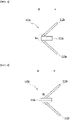
- FIGS. 1 and 2 are schematic diagrams showing a process of folding a positive electrode tab of a conventional cylindrical battery.
- the cylindrical battery 30 folds a positive electrode tab 31 using a jig 11 and a folding knife 12 of the cylindrical battery manufacturing apparatus.
- the positive electrode tab 31 is welded to a connection portion 33 of a top cap 32, and the jig 11 located on one side of the top cap 32 is moved in the first direction A to press the top cap 32, and simultaneously, the folding knife 12 located on the other side of the top cap 32 is moved in the second direction B to press a folded portion 34.
- the jig 11 and the folding knife 12 are mutually separated by a height H.
- the positive electrode tab 31 has a thin band shape with a thickness of about 0.05 to 0.3 mm, so that when the folded portion 34 is pressed and bent by the folding knife 12, the physical durability and rigidity of the folded portion 34 become weak. Thus, when a strong stress acts or a continuous stress acts on the folded portion 34 due to external vibration, there is a problem in that the folded portion 34 is disconnected.
- a cylindrical battery according to one embodiment of the present disclosure is a cylindrical battery in which electrode assembly is built into a battery case, wherein a top cap is mounted at the upper part of the electrode assembly, the top cap and the electrode assembly are electrically connected by a positive electrode tab, and the positive electrode tab includes an extension portion protruding from the folded portion of the positive electrode tab.
- the positive electrode tab may include a first connection portion and a second connection portion that are interconnected at the folded portion.
- One side of the first connection portion may be connected to the connection portion of the top cap, and the other side of the first connection portion may be connected to the folded portion.
- One side of the second connection portion may be connected to the electrode assembly, and the other side of the second connection portion may be connected to the folded portion.
- the extension portion may include a first bent portion that is bent and extended from the end of the first connection portion and a second bent portion that is bent and extended from the end of the second connection portion, and the first bent portion and the second bent portion may be mutually contacted and welded.
- the extension portion may be extended in a direction opposite to the direction in which the first connection portion and the second connection portion are extended at the folded portion.
- the extension portion may be extended in the direction in which the first connection portion and the second connection portion are extended at the folded portion, and may be formed between the first connection portion and the second connection portion.
- the extension portion may be extended in a direction opposite to the direction in which the first connection portion and the second connection portion are extended at the folded portion.
- the extension portion may include a stress distribution induction portion between the first connection portion and the second connection portion.
- the stress distribution induction portion may be a notch.
- the stress distribution induction portion may be formed in the direction in which the extension portion is extended.
- the positive electrode tab may include two or more of the extension portions.
- the positive electrode tab may include two or more folded portions.
- the positive electrode tab may be Z-shaped.
- a battery pack including the cylindrical battery according to the present disclosure as a unit battery can be provided.
- the cylindrical battery according to the embodiment of the present disclosure can prevent stress from being concentrating on the folded portion by forming an extension portion at the folded portion of the positive electrode tab.
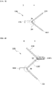
- FIG. 3 is a schematic view showing a cylindrical battery according to one embodiment of the present disclosure.
- FIG. 4 is a schematic diagram showing the positive electrode tab of FIG. 3 .
- the cylindrical battery 100 may include a top cap 101, an electrode assembly 102, and a battery case 103.
- the electrode assembly 102 may be built in the battery case 103, and a top cap 101 may be mounted at the upper part of the electrode assembly 102.
- the positive electrode tab 110 may include an extension portion 111, a first connection portion 112 and a second connection portion 113.
- One side of the first connection portion 112 may be electrically connected to a connection portion 104 of the top cap 101.
- the other side of the first connection portion 112 may have a structure connected to the folded portion S.
- One side of the second connection portion 113 may be electrically connected to the electrode assembly 102.
- the other side of the second connection portion 113 may have a structure connected to the folded portion S.
- the extension portion 111 may be extended in a direction opposite to the direction B in which the first connection portion 112 and the second connection portion 113 are extended at the folded portion S.
- the thickness T of the extension portion 111 is not particularly limited, but may be formed to be thicker than the thickness T1 of the first connection portion 112. When the thickness T of the extension portion 111 is thicker than the thickness T1 of the first connection portion 112, it becomes easy to disperse the stress concentrated in the folded portion S toward the extension portion 111.
- the thickness T of the extension portion 111 is preferably formed within a range of 100% to 600% of the thickness T1 of the first connection portion 112.
- the second connection portion 113 may be formed in a thickness identical to the thickness T1 of the first connection portion 112.
- the length L of the extension portion 111 is not particularly limited, but may be formed within a range of 10% to 40% of the diameter D (see FIG. 3 ) of the electrode assembly 102.
- the stress to be transmitted to the folded portion S due to an external impact can be dispersed toward the extension portion 111, thus making it possible to prevent the folded portion S of the positive electrode tab 110 from being disconnected.
- FIG. 5 is a schematic diagram showing a positive electrode tab according to another embodiment of the present disclosure.
- the positive electrode tab 110a may include an extension portion 111a, a first connection portion 112a, and a second connection portion 113a.
- the extension portion 111a may be extended in a direction B in which the first connection portion 112a and the second connection portion 113a are extended at the folded portion Sa.
- the extension portion 111a may be extended between the first connection portion 112a and the second connection portion 113a.
- FIG. 6 is a schematic diagram showing a positive electrode tab according to another embodiment of the present disclosure.
- the positive electrode tab 110b may include an extension portion 111b, a first connection portion 112b, and a second connection portion 113b.
- the extension portion 111b may have a structure extending simultaneously in the direction B in which the first connection portion 112b and the second connection portion 113b are extended at the folded portion Sb, and in the direction opposite thereto.
- the stress to be transmitted to the positive electrode tab 110b due to an external impact may be simultaneously dispersed in a direction B in which the first connection portion 112b and the second connection portion 113b are extended, and in the direction opposite thereto.
- FIG. 7 is a schematic diagram showing a positive electrode tab according to another embodiment of the present disclosure.
- the positive electrode tab 110c may include an extension portion 111c, a first connection portion 112c, and a second connection portion 113c.
- the extension portion 111c may have a structure extending to a direction opposite to the direction B in which the first connection portion 112c and the second connection portion 113c are extended at the folded portion Sc.
- the extension portion 111c may include a stress distribution induction portion 114 between the first connection portion 112c and the second connection portion 113c.
- the stress dispersion induction portion 114 may be a notch.
- the stress distribution induction portion 114 may be formed in a direction in which the extension portion 111c is formed.
- the stress to be transmitted to the positive electrode tab 110c due to external impact may be dispersed in the direction in which the stress distribution induction portion 114 is formed.
- the operator can to disperse the stress in a desired direction by forming the stress dispersion induction portion 114 in a specific direction.
- FIG. 8 is a schematic diagram showing a positive electrode tab according to another embodiment of the present disclosure.
- the positive electrode tab 110d may include a first extension portion 111d, a second extension portion 111d-1, a first connection portion 112d, a second connection portion 113d, and a third connection portion 115d.
- a first extension portion 111d may be formed between the first connection portion 112d and the second connection portion 113d.
- a second extension portion 111d-1 may be formed between the second connection portion 113d and the third connection portion 115d.
- the positive electrode tab 110d may be Z-shaped as a whole.
- the first bent portion S1 may be formed at a portion where the first connection portion 112d and the second connection portion 113d are connected.
- the second bent portion S2 may be formed at a portion where the second connection portion 113d and the third connection portion 115d are connected.
- the first extension portion 111d may have a structure extending in a direction opposite to the direction B in which the first connection portion 112d is extended.
- the second extension portion 111d-1 may have a structure extending in the direction B in which the first connection portion 112d is extended.
- the stress to be transmitted to the positive electrode tab 110d due to an external impact can be dispersed in the first extension portion 111d and the second extension portion 111d-1 and removed immediately.
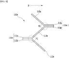
- FIG. 9 is a schematic diagram showing a positive electrode tab according to another embodiment of the present disclosure.
- the positive electrode tab 110e may include a first extension portion 111e, a second extension portion 111e-1, a first connection portion 112e, a second connection portion 113e, and a third connection portion 115e.
- a first extension portion 111e may be formed between the first connection portion 112e and the second connection portion 113e.
- a second extension portion 111e-1 may be formed between the second connection portion 113e and the third connection portion 115e.
- the positive electrode tab 110d may be Z-shaped as a whole
- a first bent portion P1 may be formed at a portion where the first connection portion 112e and the second connection portion 113e are connected.
- a second bent portion P2 may be formed at a portion where the second connection portion 113e and the third connection portion 115e are connected.
- the first extension portion 111e includes a first bent portion 112p that is bent and extended at the end of the first connection portion 112e, and a second bent portion 113p that is bent and extended at the end of the second connection portion 113e.
- the first bent portion 112p and the second bent portion 113p may have a structure extending in a direction opposite to the direction B in which the first connection portion 112e is extended. At this time, the first bent portion 112p and the second bent portion 113p may be mutually contacted and welded.
- the second extension portion 111e-1 may have a structure extending in the direction B in which the first connection portion 112e is extended.
- the second extension portion 111e-1 may include a third bent portion 113p' that is bent and extended at an end part on the side opposite to the end part of the second connection portion 113e on which the second bent portion 113p is formed, and a fourth bent portion 115p bent and extended at the end of the third connection portion 115e.
- the third bent portion 113p' and the fourth bent portion 115p may have a structure extending in a direction B in which the first connection portion 112e is extended. In this case, the third bent portion 113p' and the fourth bent portion 115p may be mutually contacted and welded.
- the stress to be transmitted to the positive electrode tab 110e due to an external impact may be dispersed in the first extension portion 111e and the second extension portion 111e-1 and can be rapidly removed.
- the positive electrode tab 110e has been described based on a case in which the positive electrode tab 110e has a Z-shape as a whole, but the contents concerning the first extension portion 111e described in the present embodiment may be modified and applied to the extension portion 111 of the embodiment in FIG. 4 .
- one or more cylindrical batteries according to the embodiment of the present disclosure can be packaged in a pack case to form a battery pack.
- the above-mentioned cylindrical battery and a battery pack may be applied to various devices. These devices may be applied to vehicles such as an electric bicycle, an electric vehicle, a hybrid vehicle, but the present disclosure is not limited thereto but can be applied to transportation means such as an electric bicycle, an electric vehicle, a hybrid vehicle, but the present disclosure is not limited thereto and can be applied to various devices that can use the cylindrical battery and the battery pack including the same, which also belongs to the scope of the present disclosure.
Landscapes
- Chemical & Material Sciences (AREA)
- Chemical Kinetics & Catalysis (AREA)
- Electrochemistry (AREA)
- General Chemical & Material Sciences (AREA)
- Connection Of Batteries Or Terminals (AREA)
- Sealing Battery Cases Or Jackets (AREA)
- Battery Mounting, Suspending (AREA)
Abstract
Description
- This application claims the benefit of
Korean Patent Application No. 10-2019-0122562 filed on October 2, 2019 Korean Patent Application No. 10-2020-0118906 filed on September 16, 2020 - The present disclosure relates to a cylindrical battery and a battery pack including the same.
- Recently, as energy prices are increasing due to the depletion of fossil fuels and increasing attention is being paid to environmental pollution, the demand for environmentally-friendly alternative energy sources acts as an essential factor for future life. Thus, research into techniques for generating various kinds of power, such as nuclear energy, solar energy, wind energy, and tidal power, is underway, and power storage apparatuses for more efficient use of the generated energy are also drawing much attention.
- Moreover, as technology development and demands for mobile devices and battery vehicles increase, the demand for batteries as energy sources is rapidly increasing. Accordingly, much research on batteries capable of meeting various needs has been carried out. In particular, in terms of the material for batteries, the demand for lithium secondary batteries, such as lithium ion batteries and lithium ion polymer batteries, which have advantages such as high energy density, discharge voltage, and output stability, is very high.
- Secondary batteries may be classified based on the structure of an electrode assembly, in which a positive electrode, a negative electrode, and a separator interposed between the positive electrode and the negative electrode are stacked. Typically, the electrode assembly may include a jelly-roll (wound) type structure in which a long sheet type positive electrode and a long sheet type negative electrode are wound in a state where a separator is disposed therebetween, or a stacked (laminated) type structure in which pluralities of positive electrodes and negative electrodes, which are cut into predetermined unit sizes, are sequentially stacked in a state where separators are disposed therebetween. Recently, in order to solve the problems involved in the jelly-roll type electrode assembly and the stack type electrode assembly, there has been developed a stacked/folded type electrode assembly having an improved structure, which is a combination of the jelly-roll type electrode assembly and the stacked type electrode assembly. The stacked/folded type electrode assembly has a structure in which unit cells stacked with certain units of the positive electrodes and the negative electrodes are sequentially wound with a separation film while a separator is interposed therebetween.
- These electrode assemblies are mounted in a pouch case, a cylindrical can, a prismatic case, and the like depending on the purpose of use to produce a battery.
- Among them, the cylindrical battery has the advantages of being easy to manufacture and having a high energy density per weight, and thus, is used as an energy source for various devices ranging from portable computers to electric vehicles.
-
FIGS. 1 and 2 are schematic diagrams showing a process of folding a positive electrode tab of a conventional cylindrical battery. - Referring to
FIGS. 1 and 2 , thecylindrical battery 30 folds apositive electrode tab 31 using ajig 11 and afolding knife 12 of the cylindrical battery manufacturing apparatus. Thepositive electrode tab 31 is welded to aconnection portion 33 of atop cap 32, and thejig 11 located on one side of thetop cap 32 is moved in the first direction A to press thetop cap 32, and simultaneously, thefolding knife 12 located on the other side of thetop cap 32 is moved in the second direction B to press a foldedportion 34. Thejig 11 and thefolding knife 12 are mutually separated by a height H. - Generally, the
positive electrode tab 31 has a thin band shape with a thickness of about 0.05 to 0.3 mm, so that when the foldedportion 34 is pressed and bent by the foldingknife 12, the physical durability and rigidity of the foldedportion 34 become weak. Thus, when a strong stress acts or a continuous stress acts on the foldedportion 34 due to external vibration, there is a problem in that the foldedportion 34 is disconnected. - It is an object of the present disclosure to provide a cylindrical battery that can prevent the positive electrode tab from being disconnected by external vibration, and a battery pack including the same.
- However, the problem to be solved by embodiments of the present disclosure is not limited to the above-described problems, and can be variously expanded within the scope of the technical idea included in the present disclosure.
- A cylindrical battery according to one embodiment of the present disclosure is a cylindrical battery in which electrode assembly is built into a battery case, wherein a top cap is mounted at the upper part of the electrode assembly, the top cap and the electrode assembly are electrically connected by a positive electrode tab, and the positive electrode tab includes an extension portion protruding from the folded portion of the positive electrode tab.
- The positive electrode tab may include a first connection portion and a second connection portion that are interconnected at the folded portion.
- One side of the first connection portion may be connected to the connection portion of the top cap, and the other side of the first connection portion may be connected to the folded portion.
- One side of the second connection portion may be connected to the electrode assembly, and the other side of the second connection portion may be connected to the folded portion.
- The extension portion may include a first bent portion that is bent and extended from the end of the first connection portion and a second bent portion that is bent and extended from the end of the second connection portion, and the first bent portion and the second bent portion may be mutually contacted and welded.
- The extension portion may be extended in a direction opposite to the direction in which the first connection portion and the second connection portion are extended at the folded portion.
- The extension portion may be extended in the direction in which the first connection portion and the second connection portion are extended at the folded portion, and may be formed between the first connection portion and the second connection portion.
- The extension portion may be extended in a direction opposite to the direction in which the first connection portion and the second connection portion are extended at the folded portion.
- The extension portion may include a stress distribution induction portion between the first connection portion and the second connection portion.
- The stress distribution induction portion may be a notch.
- The stress distribution induction portion may be formed in the direction in which the extension portion is extended.
- The positive electrode tab may include two or more of the extension portions.
- The positive electrode tab may include two or more folded portions.
- The positive electrode tab may be Z-shaped.
- A battery pack including the cylindrical battery according to the present disclosure as a unit battery can be provided.
- As described above, the cylindrical battery according to the embodiment of the present disclosure can prevent stress from being concentrating on the folded portion by forming an extension portion at the folded portion of the positive electrode tab.
-
-
FIGS. 1 and 2 are schematic diagrams showing a process of folding a positive electrode tab of a conventional cylindrical battery. -
FIG. 3 is a schematic view showing a cylindrical battery according to one embodiment of the present disclosure. -
FIG. 4 is a schematic diagram showing the positive electrode tab ofFIG. 3 . -
FIGS. 5 to 8 are schematic diagrams showing a positive electrode tab according to another embodiment of the present disclosure. -
FIG. 9 is a schematic diagram showing a positive electrode tab according to another embodiment of the present disclosure. - Hereinafter, various embodiments of the present disclosure will be described in detail with reference to the accompanying drawings so that those skilled in the art can easily implement them. The present disclosure may be modified in various different ways, and is not limited to the embodiments set forth herein.
- Further, throughout the specification, when a portion is referred to as "including" a certain component, it means that it can further include other components, without excluding the other components, unless otherwise stated.
-
FIG. 3 is a schematic view showing a cylindrical battery according to one embodiment of the present disclosure.FIG. 4 is a schematic diagram showing the positive electrode tab ofFIG. 3 . - Referring to
FIGS. 3 and 4 , thecylindrical battery 100 may include atop cap 101, anelectrode assembly 102, and abattery case 103. Theelectrode assembly 102 may be built in thebattery case 103, and atop cap 101 may be mounted at the upper part of theelectrode assembly 102. - The
positive electrode tab 110 may include anextension portion 111, afirst connection portion 112 and asecond connection portion 113. One side of thefirst connection portion 112 may be electrically connected to aconnection portion 104 of thetop cap 101. The other side of thefirst connection portion 112 may have a structure connected to the folded portion S. One side of thesecond connection portion 113 may be electrically connected to theelectrode assembly 102. The other side of thesecond connection portion 113 may have a structure connected to the folded portion S. - The
extension portion 111 may be extended in a direction opposite to the direction B in which thefirst connection portion 112 and thesecond connection portion 113 are extended at the folded portion S. The thickness T of theextension portion 111 is not particularly limited, but may be formed to be thicker than the thickness T1 of thefirst connection portion 112. When the thickness T of theextension portion 111 is thicker than the thickness T1 of thefirst connection portion 112, it becomes easy to disperse the stress concentrated in the folded portion S toward theextension portion 111. The thickness T of theextension portion 111 is preferably formed within a range of 100% to 600% of the thickness T1 of thefirst connection portion 112. Thesecond connection portion 113 may be formed in a thickness identical to the thickness T1 of thefirst connection portion 112. - The length L of the
extension portion 111 is not particularly limited, but may be formed within a range of 10% to 40% of the diameter D (seeFIG. 3 ) of theelectrode assembly 102. - With such a structure, the stress to be transmitted to the folded portion S due to an external impact can be dispersed toward the
extension portion 111, thus making it possible to prevent the folded portion S of thepositive electrode tab 110 from being disconnected. -
FIG. 5 is a schematic diagram showing a positive electrode tab according to another embodiment of the present disclosure. - Referring to
FIG. 5 , thepositive electrode tab 110a may include anextension portion 111a, afirst connection portion 112a, and asecond connection portion 113a. Theextension portion 111a may be extended in a direction B in which thefirst connection portion 112a and thesecond connection portion 113a are extended at the folded portion Sa. Theextension portion 111a may be extended between thefirst connection portion 112a and thesecond connection portion 113a. -
FIG. 6 is a schematic diagram showing a positive electrode tab according to another embodiment of the present disclosure. - Referring to
FIG. 6 , thepositive electrode tab 110b may include anextension portion 111b, afirst connection portion 112b, and asecond connection portion 113b. Theextension portion 111b may have a structure extending simultaneously in the direction B in which thefirst connection portion 112b and thesecond connection portion 113b are extended at the folded portion Sb, and in the direction opposite thereto. - With such a structure, the stress to be transmitted to the
positive electrode tab 110b due to an external impact may be simultaneously dispersed in a direction B in which thefirst connection portion 112b and thesecond connection portion 113b are extended, and in the direction opposite thereto. -
FIG. 7 is a schematic diagram showing a positive electrode tab according to another embodiment of the present disclosure. - Referring to
FIG. 7 , thepositive electrode tab 110c may include anextension portion 111c, afirst connection portion 112c, and asecond connection portion 113c. Theextension portion 111c may have a structure extending to a direction opposite to the direction B in which thefirst connection portion 112c and thesecond connection portion 113c are extended at the folded portion Sc. Further, theextension portion 111c may include a stressdistribution induction portion 114 between thefirst connection portion 112c and thesecond connection portion 113c. As an example, the stressdispersion induction portion 114 may be a notch. The stressdistribution induction portion 114 may be formed in a direction in which theextension portion 111c is formed. - With such a structure, the stress to be transmitted to the
positive electrode tab 110c due to external impact may be dispersed in the direction in which the stressdistribution induction portion 114 is formed. Through this, the operator can to disperse the stress in a desired direction by forming the stressdispersion induction portion 114 in a specific direction. -
FIG. 8 is a schematic diagram showing a positive electrode tab according to another embodiment of the present disclosure. - Referring to
FIG. 8 , thepositive electrode tab 110d may include afirst extension portion 111d, asecond extension portion 111d-1, afirst connection portion 112d, asecond connection portion 113d, and athird connection portion 115d. Afirst extension portion 111d may be formed between thefirst connection portion 112d and thesecond connection portion 113d. Asecond extension portion 111d-1 may be formed between thesecond connection portion 113d and thethird connection portion 115d. Thepositive electrode tab 110d may be Z-shaped as a whole. - The first bent portion S1 may be formed at a portion where the
first connection portion 112d and thesecond connection portion 113d are connected. The second bent portion S2 may be formed at a portion where thesecond connection portion 113d and thethird connection portion 115d are connected. - The
first extension portion 111d may have a structure extending in a direction opposite to the direction B in which thefirst connection portion 112d is extended. Thesecond extension portion 111d-1 may have a structure extending in the direction B in which thefirst connection portion 112d is extended. - With such a structure, the stress to be transmitted to the
positive electrode tab 110d due to an external impact can be dispersed in thefirst extension portion 111d and thesecond extension portion 111d-1 and removed immediately. -
FIG. 9 is a schematic diagram showing a positive electrode tab according to another embodiment of the present disclosure. - Referring to
FIG. 9 , thepositive electrode tab 110e may include afirst extension portion 111e, asecond extension portion 111e-1, afirst connection portion 112e, asecond connection portion 113e, and athird connection portion 115e. Afirst extension portion 111e may be formed between thefirst connection portion 112e and thesecond connection portion 113e. Asecond extension portion 111e-1 may be formed between thesecond connection portion 113e and thethird connection portion 115e. Thepositive electrode tab 110d may be Z-shaped as a whole - A first bent portion P1 may be formed at a portion where the
first connection portion 112e and thesecond connection portion 113e are connected. A second bent portion P2 may be formed at a portion where thesecond connection portion 113e and thethird connection portion 115e are connected. - The
first extension portion 111e includes a firstbent portion 112p that is bent and extended at the end of thefirst connection portion 112e, and a secondbent portion 113p that is bent and extended at the end of thesecond connection portion 113e. The firstbent portion 112p and the secondbent portion 113p may have a structure extending in a direction opposite to the direction B in which thefirst connection portion 112e is extended. At this time, the firstbent portion 112p and the secondbent portion 113p may be mutually contacted and welded. - The
second extension portion 111e-1 may have a structure extending in the direction B in which thefirst connection portion 112e is extended. Thesecond extension portion 111e-1 may include a thirdbent portion 113p' that is bent and extended at an end part on the side opposite to the end part of thesecond connection portion 113e on which the secondbent portion 113p is formed, and a fourthbent portion 115p bent and extended at the end of thethird connection portion 115e. The thirdbent portion 113p' and the fourthbent portion 115p may have a structure extending in a direction B in which thefirst connection portion 112e is extended. In this case, the thirdbent portion 113p' and the fourthbent portion 115p may be mutually contacted and welded. - With such a structure, the stress to be transmitted to the
positive electrode tab 110e due to an external impact may be dispersed in thefirst extension portion 111e and thesecond extension portion 111e-1 and can be rapidly removed. - In the above-described embodiment, the
positive electrode tab 110e has been described based on a case in which thepositive electrode tab 110e has a Z-shape as a whole, but the contents concerning thefirst extension portion 111e described in the present embodiment may be modified and applied to theextension portion 111 of the embodiment inFIG. 4 . - Meanwhile, one or more cylindrical batteries according to the embodiment of the present disclosure can be packaged in a pack case to form a battery pack.
- The above-mentioned cylindrical battery and a battery pack may be applied to various devices. These devices may be applied to vehicles such as an electric bicycle, an electric vehicle, a hybrid vehicle, but the present disclosure is not limited thereto but can be applied to transportation means such as an electric bicycle, an electric vehicle, a hybrid vehicle, but the present disclosure is not limited thereto and can be applied to various devices that can use the cylindrical battery and the battery pack including the same, which also belongs to the scope of the present disclosure.
- Based on the above disclosure, this is to be understood by those of ordinary skill in the art that various applications and modifications can be made within the scope of the present disclosure.
-
- 110, 110a, 110b, 110c, 110d, 110e: positive electrode tab
- 111, 111a, 111b, 111c: extension portion
- 111d, 111e: first extension portion
- 111d-1, 111e-1: second extension portion
- 112, 112a, 112b, 112c, 112d, 112e: first connection portion
- 113, 113a, 113b, 113c, 113d, 113e: second connection portion
- 114: stress dispersion induction portion
- 115d, 115e: third connection portion
- S1, P1: first bent portion
- S2, P2: second folded portion
Claims (15)
- A cylindrical battery in which electrode assembly is built into a battery case,
wherein a top cap is mounted at the upper part of the electrode assembly, the top cap and the electrode assembly are electrically connected by a positive electrode tab, and the positive electrode tab includes an extension portion protruding from the folded portion of the positive electrode tab. - The cylindrical battery according to claim 1,
wherein the positive electrode tab includes a first connection portion and a second connection portion that are interconnected at the folded portion. - The cylindrical battery according to claim 2,
wherein one side of the first connection portion is connected to the connection portion of the top cap, and the other side of the first connection portion is connected to the folded portion. - The cylindrical battery according to claim 3,
wherein one side of the second connection portion is connected to the electrode assembly, and the other side of the second connection portion is connected to the folded portion. - The cylindrical battery according to claim 2,wherein the extension portion includes a first bent portion that is bent and extended from the end of the first connection portion and a second bent portion that is bent and extended from the end of the second connection portion, andthe first bent portion and the second bent portion are mutually contacted and welded.
- The cylindrical battery according to claim 2,
wherein the extension portion is extended in a direction opposite to the direction in which the first connection portion and the second connection portion are extended at the folded portion. - The cylindrical battery according to claim 2,
wherein the extension portion is extended in the direction in which the first connection portion and the second connection portion are extended at the folded portion, and is formed between the first connection portion and the second connection portion. - The cylindrical battery according to claim 2,
wherein the extension portion is extended in a direction opposite to the direction in which the first connection portion and the second connection portion are extended at the folded portion. - The cylindrical battery according to claim 2,
wherein the extension portion includes a stress distribution induction portion between the first connection portion and the second connection portion. - The cylindrical battery according to claim 9,
wherein the stress distribution induction portion is a notch. - The cylindrical battery according to claim 9,
wherein the stress distribution induction portion is formed in the direction in which the extension portion is extended. - The cylindrical battery according to claim 1,
wherein the positive electrode tab includes two or more of the extension portions. - The cylindrical battery according to claim 12,
wherein the positive electrode tab includes two or more folded portions. - The cylindrical battery according to claim 10,
wherein the positive electrode tab is Z-shaped. - A battery pack comprising the cylindrical battery according to claim 1.
Applications Claiming Priority (3)
| Application Number | Priority Date | Filing Date | Title |
|---|---|---|---|
| KR20190122562 | 2019-10-02 | ||
| KR1020200118906A KR102849377B1 (en) | 2019-10-02 | 2020-09-16 | Cylindrical battery and battery pack including the same |
| PCT/KR2020/012545 WO2021066360A1 (en) | 2019-10-02 | 2020-09-17 | Cylindrical battery and battery pack including same |
Publications (2)
| Publication Number | Publication Date |
|---|---|
| EP3996195A1 true EP3996195A1 (en) | 2022-05-11 |
| EP3996195A4 EP3996195A4 (en) | 2022-08-24 |
Family
ID=75337189
Family Applications (1)
| Application Number | Title | Priority Date | Filing Date |
|---|---|---|---|
| EP20870910.5A Pending EP3996195A4 (en) | 2019-10-02 | 2020-09-17 | CYLINDRICAL BATTERY AND BATTERY PACK INCLUDING THE SAME |
Country Status (5)
| Country | Link |
|---|---|
| US (1) | US12438240B2 (en) |
| EP (1) | EP3996195A4 (en) |
| JP (1) | JP7351447B2 (en) |
| CN (1) | CN114128016A (en) |
| WO (1) | WO2021066360A1 (en) |
Families Citing this family (2)
| Publication number | Priority date | Publication date | Assignee | Title |
|---|---|---|---|---|
| CN219180574U (en) * | 2023-02-03 | 2023-06-13 | 比亚迪股份有限公司 | Battery processing device |
| CN116722321A (en) * | 2023-08-10 | 2023-09-08 | 宁德时代新能源科技股份有限公司 | Electrode assembly, battery cell, assembly method of battery cell, battery pack and power utilization device |
Family Cites Families (21)
| Publication number | Priority date | Publication date | Assignee | Title |
|---|---|---|---|---|
| JPH10241736A (en) | 1997-02-26 | 1998-09-11 | Rohm Co Ltd | Battery structure |
| JP2001202946A (en) * | 2000-01-18 | 2001-07-27 | Nec Corp | Secondary battery with nonaqueous electrolytic solution |
| KR100399783B1 (en) | 2001-03-05 | 2003-09-29 | 삼성에스디아이 주식회사 | Secondary battery and the fabrication method therof |
| KR100477750B1 (en) * | 2002-09-23 | 2005-03-18 | 삼성에스디아이 주식회사 | Electorde assembly for lithium ion cell and lithium ion cell using the same |
| JP4359100B2 (en) | 2003-08-04 | 2009-11-04 | 三洋電機株式会社 | Cylindrical alkaline storage battery |
| KR20060085444A (en) | 2005-01-24 | 2006-07-27 | 삼성에스디아이 주식회사 | Cylindrical secondary battery |
| KR100696786B1 (en) | 2005-04-27 | 2007-03-19 | 삼성에스디아이 주식회사 | Secondary battery |
| KR101329876B1 (en) | 2006-07-18 | 2013-11-15 | 삼성에스디아이 주식회사 | Rechargeable battery comprising electrode tab with elasticity |
| KR101287088B1 (en) | 2007-01-30 | 2013-07-17 | 삼성에스디아이 주식회사 | Rechargeabel battery |
| KR100947071B1 (en) * | 2007-11-23 | 2010-03-12 | 삼성에스디아이 주식회사 | Secondary battery |
| US9017860B2 (en) | 2009-02-26 | 2015-04-28 | Samsung Sdi Co., Ltd. | Cylinder type secondary battery |
| KR101048963B1 (en) | 2009-09-30 | 2011-07-12 | 삼성에스디아이 주식회사 | Secondary battery |
| WO2013009148A2 (en) * | 2011-07-13 | 2013-01-17 | 주식회사 엘지화학 | Cylindrical rechargeable battery |
| JP6239222B2 (en) * | 2011-10-28 | 2017-11-29 | 三洋電機株式会社 | Non-aqueous electrolyte secondary battery |
| KR101326069B1 (en) * | 2011-12-26 | 2013-11-07 | 주식회사 엘지화학 | Cap Assembly of Improved Productivity and Cylindrical Battery Cell Employed with the Same |
| KR101464964B1 (en) * | 2012-04-30 | 2014-11-25 | 주식회사 엘지화학 | Cylindrical Battery |
| KR20140017743A (en) | 2012-07-31 | 2014-02-12 | 주식회사 엘지화학 | Secondary battery with improved vibration resistance |
| KR20170010587A (en) | 2015-07-20 | 2017-02-01 | 삼성전자주식회사 | Electrode plate, Electrode Assembly and Secondary battery comprising electrode plate |
| CN106169540B (en) | 2016-08-15 | 2019-04-02 | 天臣新能源研究南京有限公司 | A kind of aluminum shell column lithium ion battery |
| KR102082914B1 (en) | 2017-09-13 | 2020-02-28 | 주식회사 엘지화학 | Secondary battery with improved safety |
| US12191511B2 (en) * | 2019-06-20 | 2025-01-07 | Apple Inc. | Battery cell with serpentine tab |
-
2020
- 2020-09-17 EP EP20870910.5A patent/EP3996195A4/en active Pending
- 2020-09-17 CN CN202080050447.3A patent/CN114128016A/en active Pending
- 2020-09-17 WO PCT/KR2020/012545 patent/WO2021066360A1/en not_active Ceased
- 2020-09-17 US US17/633,762 patent/US12438240B2/en active Active
- 2020-09-17 JP JP2022500740A patent/JP7351447B2/en active Active
Also Published As
| Publication number | Publication date |
|---|---|
| US12438240B2 (en) | 2025-10-07 |
| WO2021066360A1 (en) | 2021-04-08 |
| EP3996195A4 (en) | 2022-08-24 |
| US20220278430A1 (en) | 2022-09-01 |
| JP2022539829A (en) | 2022-09-13 |
| JP7351447B2 (en) | 2023-09-27 |
| CN114128016A (en) | 2022-03-01 |
Similar Documents
| Publication | Publication Date | Title |
|---|---|---|
| US20240213542A1 (en) | Electrode assembly and manufacturing method thereof, battery cell, battery, and electric apparatus | |
| EP3905417A1 (en) | Method for manufacturing electrode assembly, and electrode and secondary battery manufactured thereby | |
| EP2779269B1 (en) | Battery cell having a novel structure | |
| US20150318579A1 (en) | Stepped electrode assembly including stepped unit cell | |
| JP2011165672A (en) | Electrode assembly with interelectrode resistance difference of tab-lead connection part minimized and electrochemical cell equipped with the same | |
| US12358069B2 (en) | Welding apparatus, welding method using the same, and electrode assembly manufactured by the welding method | |
| KR20160092748A (en) | secondary battery | |
| KR102849377B1 (en) | Cylindrical battery and battery pack including the same | |
| US11894511B2 (en) | Cylindrical battery | |
| EP3852167B1 (en) | Battery manufacturing device and manufacturing method of battery | |
| US12438240B2 (en) | Cylindrical battery and battery pack including the same | |
| KR100893225B1 (en) | Secondary battery with improved capacity and safety | |
| EP4037078B1 (en) | Battery module comprising constant-force spring, and battery pack comprising same | |
| JP7655629B2 (en) | Separation membrane cutting device | |
| US11038247B2 (en) | Battery cell and method of manufacturing electrode lead | |
| EP3754778A1 (en) | Cylindrical secondary battery comprising piezoelectric element and thermoelectric element | |
| KR102852579B1 (en) | Ultrasonic welding horn | |
| KR102757243B1 (en) | Cylindrical secondary battery and method manufacturing the same | |
| CN118633175A (en) | Electrode plates, electrode assemblies, battery cells, batteries and electrical equipment | |
| US20230261266A1 (en) | Electrode assembly and secondary battery including the same | |
| CN120999136A (en) | Electrode assemblies, battery cells, batteries, electrical devices, manufacturing methods and equipment | |
| KR20210129541A (en) | The Electrode Assembly And The Secondary Battery | |
| JP2018085202A (en) | Battery pack |
Legal Events
| Date | Code | Title | Description |
|---|---|---|---|
| STAA | Information on the status of an ep patent application or granted ep patent |
Free format text: STATUS: THE INTERNATIONAL PUBLICATION HAS BEEN MADE |
|
| PUAI | Public reference made under article 153(3) epc to a published international application that has entered the european phase |
Free format text: ORIGINAL CODE: 0009012 |
|
| STAA | Information on the status of an ep patent application or granted ep patent |
Free format text: STATUS: REQUEST FOR EXAMINATION WAS MADE |
|
| 17P | Request for examination filed |
Effective date: 20220204 |
|
| AK | Designated contracting states |
Kind code of ref document: A1 Designated state(s): AL AT BE BG CH CY CZ DE DK EE ES FI FR GB GR HR HU IE IS IT LI LT LU LV MC MK MT NL NO PL PT RO RS SE SI SK SM TR |
|
| A4 | Supplementary search report drawn up and despatched |
Effective date: 20220725 |
|
| RIC1 | Information provided on ipc code assigned before grant |
Ipc: H01M 50/533 20210101ALI20220719BHEP Ipc: H01M 50/528 20210101ALI20220719BHEP Ipc: H01M 50/152 20210101ALI20220719BHEP Ipc: H01M 50/107 20210101AFI20220719BHEP |
|
| DAV | Request for validation of the european patent (deleted) | ||
| DAX | Request for extension of the european patent (deleted) |