EP3996168A1 - High-nickel electrode sheet having reduced reactivity with moisture and manufacturing method therefor - Google Patents
High-nickel electrode sheet having reduced reactivity with moisture and manufacturing method therefor Download PDFInfo
- Publication number
- EP3996168A1 EP3996168A1 EP21800583.3A EP21800583A EP3996168A1 EP 3996168 A1 EP3996168 A1 EP 3996168A1 EP 21800583 A EP21800583 A EP 21800583A EP 3996168 A1 EP3996168 A1 EP 3996168A1
- Authority
- EP
- European Patent Office
- Prior art keywords
- positive electrode
- active material
- mixture layer
- electrode active
- electrode mixture
- Prior art date
- Legal status (The legal status is an assumption and is not a legal conclusion. Google has not performed a legal analysis and makes no representation as to the accuracy of the status listed.)
- Pending
Links
- 238000004519 manufacturing process Methods 0.000 title claims description 28
- PXHVJJICTQNCMI-UHFFFAOYSA-N nickel Substances [Ni] PXHVJJICTQNCMI-UHFFFAOYSA-N 0.000 title abstract description 73
- 229910052759 nickel Inorganic materials 0.000 title abstract description 36
- 230000009257 reactivity Effects 0.000 title abstract description 5
- 239000000203 mixture Substances 0.000 claims abstract description 191
- 239000002002 slurry Substances 0.000 claims abstract description 39
- 238000005096 rolling process Methods 0.000 claims abstract description 29
- 239000007774 positive electrode material Substances 0.000 claims description 177
- 239000002245 particle Substances 0.000 claims description 125
- 229910052744 lithium Inorganic materials 0.000 claims description 29
- WHXSMMKQMYFTQS-UHFFFAOYSA-N Lithium Chemical compound [Li] WHXSMMKQMYFTQS-UHFFFAOYSA-N 0.000 claims description 28
- 238000000034 method Methods 0.000 claims description 19
- 239000000126 substance Substances 0.000 claims description 15
- 229910052782 aluminium Inorganic materials 0.000 claims description 12
- URIIGZKXFBNRAU-UHFFFAOYSA-N lithium;oxonickel Chemical compound [Li].[Ni]=O URIIGZKXFBNRAU-UHFFFAOYSA-N 0.000 claims description 11
- 238000002156 mixing Methods 0.000 claims description 11
- 230000008569 process Effects 0.000 claims description 11
- 229910052719 titanium Inorganic materials 0.000 claims description 9
- 150000001875 compounds Chemical class 0.000 claims description 6
- 238000001035 drying Methods 0.000 claims description 6
- 229910052748 manganese Inorganic materials 0.000 claims description 6
- 229910052726 zirconium Inorganic materials 0.000 claims description 5
- 229910052788 barium Inorganic materials 0.000 claims description 4
- 229910052791 calcium Inorganic materials 0.000 claims description 4
- 229910052749 magnesium Inorganic materials 0.000 claims description 4
- 229910052750 molybdenum Inorganic materials 0.000 claims description 4
- 229910052758 niobium Inorganic materials 0.000 claims description 4
- 229910052715 tantalum Inorganic materials 0.000 claims description 4
- 229910014915 LiaNi1-x-yCox Inorganic materials 0.000 claims description 3
- 238000005520 cutting process Methods 0.000 claims description 3
- 238000003860 storage Methods 0.000 abstract description 8
- 230000035515 penetration Effects 0.000 abstract description 2
- 230000009467 reduction Effects 0.000 abstract description 2
- 239000006182 cathode active material Substances 0.000 abstract 1
- 239000010410 layer Substances 0.000 description 126
- 239000011267 electrode slurry Substances 0.000 description 28
- -1 lithium iron phosphate compound Chemical class 0.000 description 18
- 239000011149 active material Substances 0.000 description 17
- 239000004020 conductor Substances 0.000 description 17
- OKTJSMMVPCPJKN-UHFFFAOYSA-N Carbon Chemical compound [C] OKTJSMMVPCPJKN-UHFFFAOYSA-N 0.000 description 16
- 229910000314 transition metal oxide Inorganic materials 0.000 description 13
- 239000011230 binding agent Substances 0.000 description 10
- 239000003792 electrolyte Substances 0.000 description 10
- 239000002904 solvent Substances 0.000 description 10
- SOXUFMZTHZXOGC-UHFFFAOYSA-N [Li].[Mn].[Co].[Ni] Chemical compound [Li].[Mn].[Co].[Ni] SOXUFMZTHZXOGC-UHFFFAOYSA-N 0.000 description 9
- 229910052799 carbon Inorganic materials 0.000 description 9
- 238000002360 preparation method Methods 0.000 description 9
- 229910052723 transition metal Inorganic materials 0.000 description 9
- 150000003624 transition metals Chemical class 0.000 description 9
- SECXISVLQFMRJM-UHFFFAOYSA-N N-Methylpyrrolidone Chemical compound CN1CCCC1=O SECXISVLQFMRJM-UHFFFAOYSA-N 0.000 description 8
- 230000015572 biosynthetic process Effects 0.000 description 8
- 239000010936 titanium Substances 0.000 description 8
- 239000002033 PVDF binder Substances 0.000 description 7
- 238000006243 chemical reaction Methods 0.000 description 7
- JBTWLSYIZRCDFO-UHFFFAOYSA-N ethyl methyl carbonate Chemical compound CCOC(=O)OC JBTWLSYIZRCDFO-UHFFFAOYSA-N 0.000 description 7
- 230000014759 maintenance of location Effects 0.000 description 7
- KFZMGEQAYNKOFK-UHFFFAOYSA-N Isopropanol Chemical compound CC(C)O KFZMGEQAYNKOFK-UHFFFAOYSA-N 0.000 description 6
- HBBGRARXTFLTSG-UHFFFAOYSA-N Lithium ion Chemical compound [Li+] HBBGRARXTFLTSG-UHFFFAOYSA-N 0.000 description 6
- XAGFODPZIPBFFR-UHFFFAOYSA-N aluminium Chemical compound [Al] XAGFODPZIPBFFR-UHFFFAOYSA-N 0.000 description 6
- 230000000052 comparative effect Effects 0.000 description 6
- 239000002131 composite material Substances 0.000 description 6
- 229910001416 lithium ion Inorganic materials 0.000 description 6
- 239000011572 manganese Substances 0.000 description 6
- KMTRUDSVKNLOMY-UHFFFAOYSA-N Ethylene carbonate Chemical compound O=C1OCCO1 KMTRUDSVKNLOMY-UHFFFAOYSA-N 0.000 description 5
- 239000006229 carbon black Substances 0.000 description 5
- 229920001577 copolymer Polymers 0.000 description 5
- 230000000694 effects Effects 0.000 description 5
- 239000008151 electrolyte solution Substances 0.000 description 5
- 229910003002 lithium salt Inorganic materials 0.000 description 5
- 159000000002 lithium salts Chemical class 0.000 description 5
- 239000007773 negative electrode material Substances 0.000 description 5
- 239000003960 organic solvent Substances 0.000 description 5
- 239000011148 porous material Substances 0.000 description 5
- IAZDPXIOMUYVGZ-UHFFFAOYSA-N Dimethylsulphoxide Chemical compound CS(C)=O IAZDPXIOMUYVGZ-UHFFFAOYSA-N 0.000 description 4
- VGGSQFUCUMXWEO-UHFFFAOYSA-N Ethene Chemical compound C=C VGGSQFUCUMXWEO-UHFFFAOYSA-N 0.000 description 4
- 239000005977 Ethylene Substances 0.000 description 4
- RTAQQCXQSZGOHL-UHFFFAOYSA-N Titanium Chemical compound [Ti] RTAQQCXQSZGOHL-UHFFFAOYSA-N 0.000 description 4
- 239000003575 carbonaceous material Substances 0.000 description 4
- 230000006835 compression Effects 0.000 description 4
- 238000007906 compression Methods 0.000 description 4
- IEJIGPNLZYLLBP-UHFFFAOYSA-N dimethyl carbonate Chemical compound COC(=O)OC IEJIGPNLZYLLBP-UHFFFAOYSA-N 0.000 description 4
- 230000009977 dual effect Effects 0.000 description 4
- 229910052751 metal Inorganic materials 0.000 description 4
- 239000002184 metal Substances 0.000 description 4
- 229910021382 natural graphite Inorganic materials 0.000 description 4
- 239000004745 nonwoven fabric Substances 0.000 description 4
- 229910001220 stainless steel Inorganic materials 0.000 description 4
- 239000010935 stainless steel Substances 0.000 description 4
- UHOVQNZJYSORNB-UHFFFAOYSA-N Benzene Chemical compound C1=CC=CC=C1 UHOVQNZJYSORNB-UHFFFAOYSA-N 0.000 description 3
- OIFBSDVPJOWBCH-UHFFFAOYSA-N Diethyl carbonate Chemical compound CCOC(=O)OCC OIFBSDVPJOWBCH-UHFFFAOYSA-N 0.000 description 3
- XEKOWRVHYACXOJ-UHFFFAOYSA-N Ethyl acetate Chemical compound CCOC(C)=O XEKOWRVHYACXOJ-UHFFFAOYSA-N 0.000 description 3
- ZMXDDKWLCZADIW-UHFFFAOYSA-N N,N-Dimethylformamide Chemical compound CN(C)C=O ZMXDDKWLCZADIW-UHFFFAOYSA-N 0.000 description 3
- BQCADISMDOOEFD-UHFFFAOYSA-N Silver Chemical compound [Ag] BQCADISMDOOEFD-UHFFFAOYSA-N 0.000 description 3
- 229910021383 artificial graphite Inorganic materials 0.000 description 3
- 230000008859 change Effects 0.000 description 3
- 239000011248 coating agent Substances 0.000 description 3
- 238000000576 coating method Methods 0.000 description 3
- 238000010586 diagram Methods 0.000 description 3
- 239000010408 film Substances 0.000 description 3
- 230000006872 improvement Effects 0.000 description 3
- 229910044991 metal oxide Inorganic materials 0.000 description 3
- 150000004706 metal oxides Chemical class 0.000 description 3
- 239000005518 polymer electrolyte Substances 0.000 description 3
- RUOJZAUFBMNUDX-UHFFFAOYSA-N propylene carbonate Chemical compound CC1COC(=O)O1 RUOJZAUFBMNUDX-UHFFFAOYSA-N 0.000 description 3
- 229910052709 silver Inorganic materials 0.000 description 3
- 239000004332 silver Substances 0.000 description 3
- YEJRWHAVMIAJKC-UHFFFAOYSA-N 4-Butyrolactone Chemical compound O=C1CCCO1 YEJRWHAVMIAJKC-UHFFFAOYSA-N 0.000 description 2
- CSCPPACGZOOCGX-UHFFFAOYSA-N Acetone Chemical compound CC(C)=O CSCPPACGZOOCGX-UHFFFAOYSA-N 0.000 description 2
- 229920000049 Carbon (fiber) Polymers 0.000 description 2
- CURLTUGMZLYLDI-UHFFFAOYSA-N Carbon dioxide Chemical compound O=C=O CURLTUGMZLYLDI-UHFFFAOYSA-N 0.000 description 2
- BVKZGUZCCUSVTD-UHFFFAOYSA-L Carbonate Chemical compound [O-]C([O-])=O BVKZGUZCCUSVTD-UHFFFAOYSA-L 0.000 description 2
- RYGMFSIKBFXOCR-UHFFFAOYSA-N Copper Chemical compound [Cu] RYGMFSIKBFXOCR-UHFFFAOYSA-N 0.000 description 2
- LFQSCWFLJHTTHZ-UHFFFAOYSA-N Ethanol Chemical compound CCO LFQSCWFLJHTTHZ-UHFFFAOYSA-N 0.000 description 2
- 229910001290 LiPF6 Inorganic materials 0.000 description 2
- WMFOQBRAJBCJND-UHFFFAOYSA-M Lithium hydroxide Chemical compound [Li+].[OH-] WMFOQBRAJBCJND-UHFFFAOYSA-M 0.000 description 2
- JUJWROOIHBZHMG-UHFFFAOYSA-N Pyridine Chemical compound C1=CC=NC=C1 JUJWROOIHBZHMG-UHFFFAOYSA-N 0.000 description 2
- KAESVJOAVNADME-UHFFFAOYSA-N Pyrrole Chemical compound C=1C=CNC=1 KAESVJOAVNADME-UHFFFAOYSA-N 0.000 description 2
- WYURNTSHIVDZCO-UHFFFAOYSA-N Tetrahydrofuran Chemical compound C1CCOC1 WYURNTSHIVDZCO-UHFFFAOYSA-N 0.000 description 2
- XLOMVQKBTHCTTD-UHFFFAOYSA-N Zinc monoxide Chemical compound [Zn]=O XLOMVQKBTHCTTD-UHFFFAOYSA-N 0.000 description 2
- 238000009825 accumulation Methods 0.000 description 2
- 239000000654 additive Substances 0.000 description 2
- 239000000853 adhesive Substances 0.000 description 2
- 230000001070 adhesive effect Effects 0.000 description 2
- 239000004917 carbon fiber Substances 0.000 description 2
- 229910017052 cobalt Inorganic materials 0.000 description 2
- 239000010941 cobalt Substances 0.000 description 2
- GUTLYIVDDKVIGB-UHFFFAOYSA-N cobalt atom Chemical compound [Co] GUTLYIVDDKVIGB-UHFFFAOYSA-N 0.000 description 2
- 229910052802 copper Inorganic materials 0.000 description 2
- 239000010949 copper Substances 0.000 description 2
- 150000005676 cyclic carbonates Chemical class 0.000 description 2
- JHIVVAPYMSGYDF-UHFFFAOYSA-N cyclohexanone Chemical compound O=C1CCCCC1 JHIVVAPYMSGYDF-UHFFFAOYSA-N 0.000 description 2
- 238000009826 distribution Methods 0.000 description 2
- LYCAIKOWRPUZTN-UHFFFAOYSA-N ethylene glycol Natural products OCCO LYCAIKOWRPUZTN-UHFFFAOYSA-N 0.000 description 2
- 239000000835 fiber Substances 0.000 description 2
- 239000006260 foam Substances 0.000 description 2
- 239000011888 foil Substances 0.000 description 2
- 229910002804 graphite Inorganic materials 0.000 description 2
- 239000010439 graphite Substances 0.000 description 2
- 230000002401 inhibitory effect Effects 0.000 description 2
- 150000002500 ions Chemical class 0.000 description 2
- 239000011244 liquid electrolyte Substances 0.000 description 2
- KWGKDLIKAYFUFQ-UHFFFAOYSA-M lithium chloride Chemical compound [Li+].[Cl-] KWGKDLIKAYFUFQ-UHFFFAOYSA-M 0.000 description 2
- 229910000625 lithium cobalt oxide Inorganic materials 0.000 description 2
- BFZPBUKRYWOWDV-UHFFFAOYSA-N lithium;oxido(oxo)cobalt Chemical compound [Li+].[O-][Co]=O BFZPBUKRYWOWDV-UHFFFAOYSA-N 0.000 description 2
- VNWKTOKETHGBQD-UHFFFAOYSA-N methane Chemical compound C VNWKTOKETHGBQD-UHFFFAOYSA-N 0.000 description 2
- 229920000642 polymer Polymers 0.000 description 2
- 229920006254 polymer film Polymers 0.000 description 2
- 229920000098 polyolefin Polymers 0.000 description 2
- 229920002981 polyvinylidene fluoride Polymers 0.000 description 2
- 238000003825 pressing Methods 0.000 description 2
- 238000006722 reduction reaction Methods 0.000 description 2
- 230000002441 reversible effect Effects 0.000 description 2
- 238000007789 sealing Methods 0.000 description 2
- 239000007787 solid Substances 0.000 description 2
- XOLBLPGZBRYERU-UHFFFAOYSA-N tin dioxide Chemical compound O=[Sn]=O XOLBLPGZBRYERU-UHFFFAOYSA-N 0.000 description 2
- WNXJIVFYUVYPPR-UHFFFAOYSA-N 1,3-dioxolane Chemical compound C1COCO1 WNXJIVFYUVYPPR-UHFFFAOYSA-N 0.000 description 1
- DURPTKYDGMDSBL-UHFFFAOYSA-N 1-butoxybutane Chemical compound CCCCOCCCC DURPTKYDGMDSBL-UHFFFAOYSA-N 0.000 description 1
- XNWFRZJHXBZDAG-UHFFFAOYSA-N 2-METHOXYETHANOL Chemical compound COCCO XNWFRZJHXBZDAG-UHFFFAOYSA-N 0.000 description 1
- DSMUTQTWFHVVGQ-UHFFFAOYSA-N 4,5-difluoro-1,3-dioxolan-2-one Chemical compound FC1OC(=O)OC1F DSMUTQTWFHVVGQ-UHFFFAOYSA-N 0.000 description 1
- 229910000838 Al alloy Inorganic materials 0.000 description 1
- 229920002134 Carboxymethyl cellulose Polymers 0.000 description 1
- 229910000925 Cd alloy Inorganic materials 0.000 description 1
- PIICEJLVQHRZGT-UHFFFAOYSA-N Ethylenediamine Chemical compound NCCN PIICEJLVQHRZGT-UHFFFAOYSA-N 0.000 description 1
- 229920002153 Hydroxypropyl cellulose Polymers 0.000 description 1
- 229910001559 LiC4F9SO3 Inorganic materials 0.000 description 1
- 229910000552 LiCF3SO3 Inorganic materials 0.000 description 1
- 229910052493 LiFePO4 Inorganic materials 0.000 description 1
- 229910002993 LiMnO2 Inorganic materials 0.000 description 1
- 229910013131 LiN Inorganic materials 0.000 description 1
- 229910002097 Lithium manganese(III,IV) oxide Inorganic materials 0.000 description 1
- PWHULOQIROXLJO-UHFFFAOYSA-N Manganese Chemical compound [Mn] PWHULOQIROXLJO-UHFFFAOYSA-N 0.000 description 1
- VEQPNABPJHWNSG-UHFFFAOYSA-N Nickel(2+) Chemical compound [Ni+2] VEQPNABPJHWNSG-UHFFFAOYSA-N 0.000 description 1
- 229910019142 PO4 Inorganic materials 0.000 description 1
- 239000004698 Polyethylene Substances 0.000 description 1
- 229920000265 Polyparaphenylene Polymers 0.000 description 1
- 239000004743 Polypropylene Substances 0.000 description 1
- 239000004372 Polyvinyl alcohol Substances 0.000 description 1
- XBDQKXXYIPTUBI-UHFFFAOYSA-M Propionate Chemical compound CCC([O-])=O XBDQKXXYIPTUBI-UHFFFAOYSA-M 0.000 description 1
- 229910000676 Si alloy Inorganic materials 0.000 description 1
- VYPSYNLAJGMNEJ-UHFFFAOYSA-N Silicium dioxide Chemical compound O=[Si]=O VYPSYNLAJGMNEJ-UHFFFAOYSA-N 0.000 description 1
- 229910001128 Sn alloy Inorganic materials 0.000 description 1
- 229920002472 Starch Polymers 0.000 description 1
- NINIDFKCEFEMDL-UHFFFAOYSA-N Sulfur Chemical compound [S] NINIDFKCEFEMDL-UHFFFAOYSA-N 0.000 description 1
- GWEVSGVZZGPLCZ-UHFFFAOYSA-N Titan oxide Chemical compound O=[Ti]=O GWEVSGVZZGPLCZ-UHFFFAOYSA-N 0.000 description 1
- GSEJCLTVZPLZKY-UHFFFAOYSA-N Triethanolamine Chemical compound OCCN(CCO)CCO GSEJCLTVZPLZKY-UHFFFAOYSA-N 0.000 description 1
- RLTFLELMPUMVEH-UHFFFAOYSA-N [Li+].[O--].[O--].[O--].[V+5] Chemical compound [Li+].[O--].[O--].[O--].[V+5] RLTFLELMPUMVEH-UHFFFAOYSA-N 0.000 description 1
- XHCLAFWTIXFWPH-UHFFFAOYSA-N [O-2].[O-2].[O-2].[O-2].[O-2].[V+5].[V+5] Chemical compound [O-2].[O-2].[O-2].[O-2].[O-2].[V+5].[V+5] XHCLAFWTIXFWPH-UHFFFAOYSA-N 0.000 description 1
- KXKVLQRXCPHEJC-UHFFFAOYSA-N acetic acid trimethyl ester Natural products COC(C)=O KXKVLQRXCPHEJC-UHFFFAOYSA-N 0.000 description 1
- 239000006230 acetylene black Substances 0.000 description 1
- 230000000996 additive effect Effects 0.000 description 1
- 239000005456 alcohol based solvent Substances 0.000 description 1
- 238000005275 alloying Methods 0.000 description 1
- VSCWAEJMTAWNJL-UHFFFAOYSA-K aluminium trichloride Chemical compound Cl[Al](Cl)Cl VSCWAEJMTAWNJL-UHFFFAOYSA-K 0.000 description 1
- 150000001408 amides Chemical class 0.000 description 1
- 150000003863 ammonium salts Chemical class 0.000 description 1
- 229910003481 amorphous carbon Inorganic materials 0.000 description 1
- 150000004945 aromatic hydrocarbons Chemical class 0.000 description 1
- 125000003118 aryl group Chemical group 0.000 description 1
- 230000008901 benefit Effects 0.000 description 1
- 229910052797 bismuth Inorganic materials 0.000 description 1
- IAQRGUVFOMOMEM-UHFFFAOYSA-N butene Natural products CC=CC IAQRGUVFOMOMEM-UHFFFAOYSA-N 0.000 description 1
- 239000006227 byproduct Substances 0.000 description 1
- 229910052793 cadmium Inorganic materials 0.000 description 1
- 229910002092 carbon dioxide Inorganic materials 0.000 description 1
- 239000001569 carbon dioxide Substances 0.000 description 1
- 239000003660 carbonate based solvent Substances 0.000 description 1
- 238000005266 casting Methods 0.000 description 1
- 239000000919 ceramic Substances 0.000 description 1
- 150000005678 chain carbonates Chemical class 0.000 description 1
- 239000006231 channel black Substances 0.000 description 1
- 239000011294 coal tar pitch Substances 0.000 description 1
- 239000000571 coke Substances 0.000 description 1
- 239000002322 conducting polymer Substances 0.000 description 1
- 229920001940 conductive polymer Polymers 0.000 description 1
- 230000008878 coupling Effects 0.000 description 1
- 238000010168 coupling process Methods 0.000 description 1
- 238000005859 coupling reaction Methods 0.000 description 1
- 150000004292 cyclic ethers Chemical class 0.000 description 1
- 125000000753 cycloalkyl group Chemical group 0.000 description 1
- 230000007423 decrease Effects 0.000 description 1
- 238000009831 deintercalation Methods 0.000 description 1
- 150000004862 dioxolanes Chemical class 0.000 description 1
- NJLLQSBAHIKGKF-UHFFFAOYSA-N dipotassium dioxido(oxo)titanium Chemical compound [K+].[K+].[O-][Ti]([O-])=O NJLLQSBAHIKGKF-UHFFFAOYSA-N 0.000 description 1
- 239000002612 dispersion medium Substances 0.000 description 1
- 238000003487 electrochemical reaction Methods 0.000 description 1
- 239000007772 electrode material Substances 0.000 description 1
- 238000005516 engineering process Methods 0.000 description 1
- 239000003759 ester based solvent Substances 0.000 description 1
- 235000019441 ethanol Nutrition 0.000 description 1
- RTZKZFJDLAIYFH-UHFFFAOYSA-N ether Chemical group CCOCC RTZKZFJDLAIYFH-UHFFFAOYSA-N 0.000 description 1
- 239000004210 ether based solvent Substances 0.000 description 1
- 238000011156 evaluation Methods 0.000 description 1
- 238000011049 filling Methods 0.000 description 1
- 229920001973 fluoroelastomer Polymers 0.000 description 1
- 239000006232 furnace black Substances 0.000 description 1
- 239000003365 glass fiber Substances 0.000 description 1
- 239000011357 graphitized carbon fiber Substances 0.000 description 1
- 229910021385 hard carbon Inorganic materials 0.000 description 1
- 229920001519 homopolymer Polymers 0.000 description 1
- 239000001863 hydroxypropyl cellulose Substances 0.000 description 1
- 235000010977 hydroxypropyl cellulose Nutrition 0.000 description 1
- 229910052738 indium Inorganic materials 0.000 description 1
- 238000009830 intercalation Methods 0.000 description 1
- 230000002687 intercalation Effects 0.000 description 1
- 229910000765 intermetallic Inorganic materials 0.000 description 1
- 239000003273 ketjen black Substances 0.000 description 1
- 239000005453 ketone based solvent Substances 0.000 description 1
- 238000010030 laminating Methods 0.000 description 1
- 239000006233 lamp black Substances 0.000 description 1
- 238000007561 laser diffraction method Methods 0.000 description 1
- 229910052745 lead Inorganic materials 0.000 description 1
- XGZVUEUWXADBQD-UHFFFAOYSA-L lithium carbonate Chemical compound [Li+].[Li+].[O-]C([O-])=O XGZVUEUWXADBQD-UHFFFAOYSA-L 0.000 description 1
- 229910052808 lithium carbonate Inorganic materials 0.000 description 1
- 229910001547 lithium hexafluoroantimonate(V) Inorganic materials 0.000 description 1
- 229910001540 lithium hexafluoroarsenate(V) Inorganic materials 0.000 description 1
- 229910002102 lithium manganese oxide Inorganic materials 0.000 description 1
- MHCFAGZWMAWTNR-UHFFFAOYSA-M lithium perchlorate Chemical compound [Li+].[O-]Cl(=O)(=O)=O MHCFAGZWMAWTNR-UHFFFAOYSA-M 0.000 description 1
- 229910001486 lithium perchlorate Inorganic materials 0.000 description 1
- 229910001537 lithium tetrachloroaluminate Inorganic materials 0.000 description 1
- 229910001496 lithium tetrafluoroborate Inorganic materials 0.000 description 1
- 229910000686 lithium vanadium oxide Inorganic materials 0.000 description 1
- ACFSQHQYDZIPRL-UHFFFAOYSA-N lithium;bis(1,1,2,2,2-pentafluoroethylsulfonyl)azanide Chemical compound [Li+].FC(F)(F)C(F)(F)S(=O)(=O)[N-]S(=O)(=O)C(F)(F)C(F)(F)F ACFSQHQYDZIPRL-UHFFFAOYSA-N 0.000 description 1
- QSZMZKBZAYQGRS-UHFFFAOYSA-N lithium;bis(trifluoromethylsulfonyl)azanide Chemical compound [Li+].FC(F)(F)S(=O)(=O)[N-]S(=O)(=O)C(F)(F)F QSZMZKBZAYQGRS-UHFFFAOYSA-N 0.000 description 1
- VROAXDSNYPAOBJ-UHFFFAOYSA-N lithium;oxido(oxo)nickel Chemical compound [Li+].[O-][Ni]=O VROAXDSNYPAOBJ-UHFFFAOYSA-N 0.000 description 1
- VLXXBCXTUVRROQ-UHFFFAOYSA-N lithium;oxido-oxo-(oxomanganiooxy)manganese Chemical compound [Li+].[O-][Mn](=O)O[Mn]=O VLXXBCXTUVRROQ-UHFFFAOYSA-N 0.000 description 1
- 239000000463 material Substances 0.000 description 1
- 238000005259 measurement Methods 0.000 description 1
- 239000002609 medium Substances 0.000 description 1
- 238000002844 melting Methods 0.000 description 1
- 230000008018 melting Effects 0.000 description 1
- 239000002931 mesocarbon microbead Substances 0.000 description 1
- 239000011302 mesophase pitch Substances 0.000 description 1
- 150000002736 metal compounds Chemical class 0.000 description 1
- 230000000116 mitigating effect Effects 0.000 description 1
- PYLWMHQQBFSUBP-UHFFFAOYSA-N monofluorobenzene Chemical compound FC1=CC=CC=C1 PYLWMHQQBFSUBP-UHFFFAOYSA-N 0.000 description 1
- 229910001453 nickel ion Inorganic materials 0.000 description 1
- 150000002825 nitriles Chemical class 0.000 description 1
- 150000005181 nitrobenzenes Chemical class 0.000 description 1
- 239000005486 organic electrolyte Substances 0.000 description 1
- 230000003647 oxidation Effects 0.000 description 1
- 238000007254 oxidation reaction Methods 0.000 description 1
- 239000011301 petroleum pitch Substances 0.000 description 1
- NBIIXXVUZAFLBC-UHFFFAOYSA-K phosphate Chemical compound [O-]P([O-])([O-])=O NBIIXXVUZAFLBC-UHFFFAOYSA-K 0.000 description 1
- 239000010452 phosphate Substances 0.000 description 1
- 239000011295 pitch Substances 0.000 description 1
- 229920002239 polyacrylonitrile Polymers 0.000 description 1
- 229920000573 polyethylene Polymers 0.000 description 1
- 229920000139 polyethylene terephthalate Polymers 0.000 description 1
- 239000005020 polyethylene terephthalate Substances 0.000 description 1
- 239000002861 polymer material Substances 0.000 description 1
- 229920001155 polypropylene Polymers 0.000 description 1
- 239000004810 polytetrafluoroethylene Substances 0.000 description 1
- 229920001343 polytetrafluoroethylene Polymers 0.000 description 1
- 229920002451 polyvinyl alcohol Polymers 0.000 description 1
- 229920000036 polyvinylpyrrolidone Polymers 0.000 description 1
- 239000001267 polyvinylpyrrolidone Substances 0.000 description 1
- 235000013855 polyvinylpyrrolidone Nutrition 0.000 description 1
- 239000000843 powder Substances 0.000 description 1
- 238000001556 precipitation Methods 0.000 description 1
- 229920001384 propylene homopolymer Polymers 0.000 description 1
- 238000004080 punching Methods 0.000 description 1
- UMJSCPRVCHMLSP-UHFFFAOYSA-N pyridine Natural products COC1=CC=CN=C1 UMJSCPRVCHMLSP-UHFFFAOYSA-N 0.000 description 1
- 239000002296 pyrolytic carbon Substances 0.000 description 1
- 239000001008 quinone-imine dye Substances 0.000 description 1
- 239000004627 regenerated cellulose Substances 0.000 description 1
- 229910052710 silicon Inorganic materials 0.000 description 1
- 229910052814 silicon oxide Inorganic materials 0.000 description 1
- 239000002153 silicon-carbon composite material Substances 0.000 description 1
- 239000002356 single layer Substances 0.000 description 1
- 238000007581 slurry coating method Methods 0.000 description 1
- 229910021384 soft carbon Inorganic materials 0.000 description 1
- 239000000243 solution Substances 0.000 description 1
- 239000008107 starch Substances 0.000 description 1
- 235000019698 starch Nutrition 0.000 description 1
- 229920003048 styrene butadiene rubber Polymers 0.000 description 1
- HXJUTPCZVOIRIF-UHFFFAOYSA-N sulfolane Chemical compound O=S1(=O)CCCC1 HXJUTPCZVOIRIF-UHFFFAOYSA-N 0.000 description 1
- 229920005608 sulfonated EPDM Polymers 0.000 description 1
- 229910052717 sulfur Inorganic materials 0.000 description 1
- 239000011593 sulfur Substances 0.000 description 1
- YLQBMQCUIZJEEH-UHFFFAOYSA-N tetrahydrofuran Natural products C=1C=COC=1 YLQBMQCUIZJEEH-UHFFFAOYSA-N 0.000 description 1
- 239000010409 thin film Substances 0.000 description 1
- 229910052718 tin Inorganic materials 0.000 description 1
- 239000002733 tin-carbon composite material Substances 0.000 description 1
- OGIDPMRJRNCKJF-UHFFFAOYSA-N titanium oxide Inorganic materials [Ti]=O OGIDPMRJRNCKJF-UHFFFAOYSA-N 0.000 description 1
- BDZBKCUKTQZUTL-UHFFFAOYSA-N triethyl phosphite Chemical compound CCOP(OCC)OCC BDZBKCUKTQZUTL-UHFFFAOYSA-N 0.000 description 1
- 229910001935 vanadium oxide Inorganic materials 0.000 description 1
- XLYOFNOQVPJJNP-UHFFFAOYSA-N water Substances O XLYOFNOQVPJJNP-UHFFFAOYSA-N 0.000 description 1
- 235000015041 whisky Nutrition 0.000 description 1
- 229910052725 zinc Inorganic materials 0.000 description 1
- 239000011701 zinc Substances 0.000 description 1
- 239000011787 zinc oxide Substances 0.000 description 1
- PAPBSGBWRJIAAV-UHFFFAOYSA-N ε-Caprolactone Chemical compound O=C1CCCCCO1 PAPBSGBWRJIAAV-UHFFFAOYSA-N 0.000 description 1
Images


Classifications
-
- H—ELECTRICITY
- H01—ELECTRIC ELEMENTS
- H01M—PROCESSES OR MEANS, e.g. BATTERIES, FOR THE DIRECT CONVERSION OF CHEMICAL ENERGY INTO ELECTRICAL ENERGY
- H01M4/00—Electrodes
- H01M4/02—Electrodes composed of, or comprising, active material
- H01M4/13—Electrodes for accumulators with non-aqueous electrolyte, e.g. for lithium-accumulators; Processes of manufacture thereof
- H01M4/131—Electrodes based on mixed oxides or hydroxides, or on mixtures of oxides or hydroxides, e.g. LiCoOx
-
- H—ELECTRICITY
- H01—ELECTRIC ELEMENTS
- H01M—PROCESSES OR MEANS, e.g. BATTERIES, FOR THE DIRECT CONVERSION OF CHEMICAL ENERGY INTO ELECTRICAL ENERGY
- H01M4/00—Electrodes
- H01M4/02—Electrodes composed of, or comprising, active material
- H01M4/13—Electrodes for accumulators with non-aqueous electrolyte, e.g. for lithium-accumulators; Processes of manufacture thereof
-
- H—ELECTRICITY
- H01—ELECTRIC ELEMENTS
- H01M—PROCESSES OR MEANS, e.g. BATTERIES, FOR THE DIRECT CONVERSION OF CHEMICAL ENERGY INTO ELECTRICAL ENERGY
- H01M10/00—Secondary cells; Manufacture thereof
- H01M10/04—Construction or manufacture in general
- H01M10/0404—Machines for assembling batteries
-
- H—ELECTRICITY
- H01—ELECTRIC ELEMENTS
- H01M—PROCESSES OR MEANS, e.g. BATTERIES, FOR THE DIRECT CONVERSION OF CHEMICAL ENERGY INTO ELECTRICAL ENERGY
- H01M10/00—Secondary cells; Manufacture thereof
- H01M10/05—Accumulators with non-aqueous electrolyte
- H01M10/052—Li-accumulators
- H01M10/0525—Rocking-chair batteries, i.e. batteries with lithium insertion or intercalation in both electrodes; Lithium-ion batteries
-
- H—ELECTRICITY
- H01—ELECTRIC ELEMENTS
- H01M—PROCESSES OR MEANS, e.g. BATTERIES, FOR THE DIRECT CONVERSION OF CHEMICAL ENERGY INTO ELECTRICAL ENERGY
- H01M4/00—Electrodes
- H01M4/02—Electrodes composed of, or comprising, active material
- H01M4/04—Processes of manufacture in general
- H01M4/0402—Methods of deposition of the material
- H01M4/0404—Methods of deposition of the material by coating on electrode collectors
-
- H—ELECTRICITY
- H01—ELECTRIC ELEMENTS
- H01M—PROCESSES OR MEANS, e.g. BATTERIES, FOR THE DIRECT CONVERSION OF CHEMICAL ENERGY INTO ELECTRICAL ENERGY
- H01M4/00—Electrodes
- H01M4/02—Electrodes composed of, or comprising, active material
- H01M4/04—Processes of manufacture in general
- H01M4/043—Processes of manufacture in general involving compressing or compaction
- H01M4/0435—Rolling or calendering
-
- H—ELECTRICITY
- H01—ELECTRIC ELEMENTS
- H01M—PROCESSES OR MEANS, e.g. BATTERIES, FOR THE DIRECT CONVERSION OF CHEMICAL ENERGY INTO ELECTRICAL ENERGY
- H01M4/00—Electrodes
- H01M4/02—Electrodes composed of, or comprising, active material
- H01M4/04—Processes of manufacture in general
- H01M4/0471—Processes of manufacture in general involving thermal treatment, e.g. firing, sintering, backing particulate active material, thermal decomposition, pyrolysis
-
- H—ELECTRICITY
- H01—ELECTRIC ELEMENTS
- H01M—PROCESSES OR MEANS, e.g. BATTERIES, FOR THE DIRECT CONVERSION OF CHEMICAL ENERGY INTO ELECTRICAL ENERGY
- H01M4/00—Electrodes
- H01M4/02—Electrodes composed of, or comprising, active material
- H01M4/13—Electrodes for accumulators with non-aqueous electrolyte, e.g. for lithium-accumulators; Processes of manufacture thereof
- H01M4/139—Processes of manufacture
- H01M4/1391—Processes of manufacture of electrodes based on mixed oxides or hydroxides, or on mixtures of oxides or hydroxides, e.g. LiCoOx
-
- H—ELECTRICITY
- H01—ELECTRIC ELEMENTS
- H01M—PROCESSES OR MEANS, e.g. BATTERIES, FOR THE DIRECT CONVERSION OF CHEMICAL ENERGY INTO ELECTRICAL ENERGY
- H01M4/00—Electrodes
- H01M4/02—Electrodes composed of, or comprising, active material
- H01M4/36—Selection of substances as active materials, active masses, active liquids
- H01M4/48—Selection of substances as active materials, active masses, active liquids of inorganic oxides or hydroxides
- H01M4/50—Selection of substances as active materials, active masses, active liquids of inorganic oxides or hydroxides of manganese
- H01M4/505—Selection of substances as active materials, active masses, active liquids of inorganic oxides or hydroxides of manganese of mixed oxides or hydroxides containing manganese for inserting or intercalating light metals, e.g. LiMn2O4 or LiMn2OxFy
-
- H—ELECTRICITY
- H01—ELECTRIC ELEMENTS
- H01M—PROCESSES OR MEANS, e.g. BATTERIES, FOR THE DIRECT CONVERSION OF CHEMICAL ENERGY INTO ELECTRICAL ENERGY
- H01M4/00—Electrodes
- H01M4/02—Electrodes composed of, or comprising, active material
- H01M4/36—Selection of substances as active materials, active masses, active liquids
- H01M4/48—Selection of substances as active materials, active masses, active liquids of inorganic oxides or hydroxides
- H01M4/52—Selection of substances as active materials, active masses, active liquids of inorganic oxides or hydroxides of nickel, cobalt or iron
- H01M4/525—Selection of substances as active materials, active masses, active liquids of inorganic oxides or hydroxides of nickel, cobalt or iron of mixed oxides or hydroxides containing iron, cobalt or nickel for inserting or intercalating light metals, e.g. LiNiO2, LiCoO2 or LiCoOxFy
-
- H—ELECTRICITY
- H01—ELECTRIC ELEMENTS
- H01M—PROCESSES OR MEANS, e.g. BATTERIES, FOR THE DIRECT CONVERSION OF CHEMICAL ENERGY INTO ELECTRICAL ENERGY
- H01M4/00—Electrodes
- H01M4/02—Electrodes composed of, or comprising, active material
- H01M2004/021—Physical characteristics, e.g. porosity, surface area
-
- H—ELECTRICITY
- H01—ELECTRIC ELEMENTS
- H01M—PROCESSES OR MEANS, e.g. BATTERIES, FOR THE DIRECT CONVERSION OF CHEMICAL ENERGY INTO ELECTRICAL ENERGY
- H01M4/00—Electrodes
- H01M4/02—Electrodes composed of, or comprising, active material
- H01M2004/026—Electrodes composed of, or comprising, active material characterised by the polarity
- H01M2004/028—Positive electrodes
-
- Y—GENERAL TAGGING OF NEW TECHNOLOGICAL DEVELOPMENTS; GENERAL TAGGING OF CROSS-SECTIONAL TECHNOLOGIES SPANNING OVER SEVERAL SECTIONS OF THE IPC; TECHNICAL SUBJECTS COVERED BY FORMER USPC CROSS-REFERENCE ART COLLECTIONS [XRACs] AND DIGESTS
- Y02—TECHNOLOGIES OR APPLICATIONS FOR MITIGATION OR ADAPTATION AGAINST CLIMATE CHANGE
- Y02E—REDUCTION OF GREENHOUSE GAS [GHG] EMISSIONS, RELATED TO ENERGY GENERATION, TRANSMISSION OR DISTRIBUTION
- Y02E60/00—Enabling technologies; Technologies with a potential or indirect contribution to GHG emissions mitigation
- Y02E60/10—Energy storage using batteries
Definitions
- the present invention relates to an electrode sheet of a positive electrode containing a positive electrode active material having a high content of nickel, and a method of manufacturing the same, and more particularly, to an electrode sheet capable of suppressing reactivity with moisture by applying a slurry for a second positive electrode mixture including a positive electrode active material having a particle strength resistant to rolling at both edge regions of the electrode sheet coated part, to which moisture may be easily permeated during the storage of the electrode sheet, than the central portion of the coated part, and a method of manufacturing the electrode sheet.
- the lithium secondary battery in a state that an organic electrolyte solution or a polymer electrolyte solution is charged in a space between a positive electrode and a negative electrode which are made of an active material in which lithium ions may be intercalated and deintercalated, electric energy is generated by oxidation and reduction reactions when lithium ions are intercalated/deintercalated in the positive electrode and the negative electrode.
- Lithium cobalt oxide (LiCoO 2 ), lithium nickel oxide (LiNiO 2 ), lithium manganese oxide (LiMnO 2 or LiMn 2 O 4 , etc.), lithium iron phosphate compound (LiFePO 4 ) and the like were used as the positive electrode active material of a lithium secondary battery. Further, as a method for improving a low thermal stability while maintaining the excellent reversible capacity of LiNiO 2 , a lithium composite metal oxide (hereinafter, referred to as "NCM-based lithium composite transition metal oxide”), which was generated by substituting a part of nickel (Ni) with cobalt (CO) and manganese (Mn), was developed. However, the conventional NCM-based lithium composite transition metal oxide was not sufficient in capacity characteristics and thus has a limit in its application.
- nickel in the NCM-based lithium composite transition metal oxide In order to improve such a problem, in recent years, research is conducted to increase the content of nickel in the NCM-based lithium composite transition metal oxide. As the content of nickel increases, the energy density per volume increases, but in the case of a high concentration nickel positive electrode active material, there is a problem that the structural stability and the chemical stability of the active material are low, which again rapidly deteriorates the thermal stability. Further, nickel ions react with moisture and carbon dioxide present in the storage environment, and irreversibly switched to NiO, and in this process, lithium ions exit, and lithium byproducts existing in the form of LiOH and Li 2 CO 3 increase. As such, the resistance of the surface of the active material increases, the capacity of the battery decreases, and gas generation during high temperature storage increases.
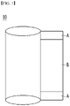
- the electrode sheet which is generated by applying a slurry for an electrode mixture including an electrode active material on a current collector sheet, and then performing a drying and rolling process, is stored in a wound state until punching the electrode for the assembly of a battery.
- FIG. 1 shows an electrode sheet 10 in a wound state for storage.
- moisture maybe more easily permeated into the both ends (A) than the central portion of the coated part, based on the width direction (arrow) of the electrode sheet, and thus the moisture content is high in the both ends (A). Therefore, in the case of a positive electrode sheet including a positive electrode active material of the NCM-based lithium composite transition metal oxide, the probability of reaction of nickel with moisture is higher in the both ends than in the central portion.
- Japanese Patent Publication No. 2019-149269 discloses a secondary battery including a positive electrode, in which a first positive electrode active material having a nickel content of 50 to 80% is applied in the center, and a second positive electrode active material a nickel content of 20 to 40% is applied at both ends.
- the conventional technology has the effect of suppressing the precipitation of lithium, but it is not sufficient for improving the lifespan of the battery, and the second positive electrode active material applied to both ends has the nickel content of only 20 to 40%, and thus it is difficult to implement the desired energy density.
- the present invention has been created to solve the above problems, and it is an object of the present invention to provide an electrode sheet in the form that is wound by a roll, capable of mitigating the reaction of the positive electrode active material having a high nickel content with moisture while implementing a high energy density, and a manufacturing method thereof.
- An electrode sheet of the present invention for solving the above problems is an electrode sheet including a non-coated part and a coated part in which a positive electrode mixture layer is applied on at least one surface of a current collector, wherein the coated part includes: a first positive electrode mixture layer configured to be formed on a central portion along a longitudinal direction of the electrode sheet and to contain a positive electrode active material of lithium nickel oxide; and a second positive electrode mixture layer configured to be formed at one or two edges of the first positive electrode mixture layer and to contain a positive electrode active material of lithium nickel oxide, and wherein a particle strength of the positive electrode active material in the second positive electrode mixture layer is greater than a particle strength of the positive electrode active material in the first positive electrode mixture layer.
- a width of the second positive electrode mixture layer corresponds to 1 to 15% of a width of the first positive electrode mixture layer.
- positive electrode active materials which are respectively contained in the first positive electrode mixture layer and the second positive electrode mixture layer, independently contain a compound represented by Chemical Formula 1 below: [Chemical formula 1] Li a Ni 1-x-y CO x M1 y M2 w O 2 ,
- a ratio B/A of the particle strength B of the positive electrode active material particle in the second positive electrode mixture layer to the particle strength A of the positive electrode active material in the first positive electrode mixture layer is in a range of 1.01 to 1.5.
- the second positive electrode mixture layer contains a mixture of first positive electrode active materials having a relatively large average particle size D 50 and second positive electrode active materials having a relatively small average particle size D 50 .
- the average particle size D 50 of the first positive electrode active material is in a range of 9 ⁇ m to 30 ⁇ m, and the average particle size D 50 of the second positive electrode active material is less than 9 ⁇ m.
- a mixing ratio of the first positive electrode active material and the second positive electrode active material is in a range of 95: 5 to 65: 35 based on a weight.
- the positive electrode active material of the first positive electrode mixture layer may be made of the positive electrode active material having the same average particle size D 50 .
- the average particle size D 50 of the positive electrode active material of the first positive electrode mixture layer may be in a range of 9 ⁇ m to 30 ⁇ m.
- the first positive electrode mixture layer may contain a mixture of first positive electrode active materials having a relatively large average particle size D 50 and second positive electrode active materials having a relatively small average particle size D 50 .
- the average particle size D 50 of the first positive electrode active material may be in a range of 9 ⁇ m to 30 ⁇ m, and the average particle size D 50 of the second positive electrode active material may be less than 9 ⁇ m.
- a ratio (b/a) of a weight (b) of the second positive electrode active material to a weight (a) of the first positive electrode active material in the second positive electrode mixture layer is greater than a ratio (b'/a') of a weight (b') of the second positive electrode active material to a weight (a') of the first positive electrode active material in the first positive electrode mixture layer.
- a lithium secondary battery of the present invention includes a positive electrode generated by cutting the coated part and the non-coated part of the electrode sheet according to a shape and a size of a unit electrode.
- a method for manufacturing an electrode sheet according to the present invention includes: a slurry manufacturing process of manufacturing a slurry for a first positive electrode mixture and a slurry for a second positive electrode mixture, respectively; an applying process of applying the slurry for the first positive electrode mixture and the slurry for the second positive electrode mixture to thereby form a first positive electrode mixture layer and a second positive electrode mixture layer; a drying process; and a rolling process, wherein in the applying process, the slurry for the first positive electrode mixture has a predetermined width at a central portion of the electrode sheet based on a width direction of the electrode sheet and is applied in a longitudinal direction of the electrode sheet, and the slurry for the second positive electrode mixture has a predetermined width at an edge of one side or both sides of the slurry for the first positive electrode mixture and is applied in a longitudinal direction of the electrode sheet, and wherein the slurry for the second positive electrode mixture contains a mixture of first positive electrode active materials having a relatively large average particle size D 50 and second positive electrode active materials having
- a length of a width of the second positive electrode mixture layer corresponds to 1 to 15% of a length of a width of the first positive electrode mixture layer.
- the electrode sheet of the present invention by including a positive electrode active material having a particle strength, which is greater than that of the first positive electrode mixture layer, in a second positive electrode mixture layer at both edges of the electrode sheet coated part which is easy to be exposed to moisture and where particles may be relatively easily broken due to the rolling roll of a worn structure, the reaction of the second positive electrode mixture layer with moisture after rolling is minimized, thereby improving lifespan characteristics of the battery.
- the electrode sheet of the present invention capacity characteristics of the battery are improved by being applied to a high nickel positive electrode material having a high energy density.
- An electrode sheet is an electrode sheet including a non-coated part and a coated part in which a positive electrode mixture layer is applied on at least one surface of a current collector, wherein the coated part includes: a first positive electrode mixture layer configured to be formed on a central portion along a longitudinal direction of the electrode sheet and to contain a positive electrode active material of lithium nickel oxide; and a second positive electrode mixture layer configured to be formed at one or two edges of the first positive electrode mixture layer and to contain a positive electrode active material of lithium nickel oxide, and wherein a particle strength of the positive electrode active material in the second positive electrode mixture layer is greater than a particle strength of the positive electrode active material in the first positive electrode mixture layer.
- FIG. 2 is a graph showing the moisture content in an electrode according to an electrode manufacturing step. Referring to this, it can be seen that the moisture content in the electrode is increased by a large width in the electrode immediately after the rolling process. This is because, as the electrode is rolled by a large force, the active material particles in the electrode layer are broken, thereby rapidly increasing the specific surface area of the active materials.
- the rolling roller for rolling the electrode sheet may show a high rolling rate at both ends of the roller due to the structure, wear, etc.
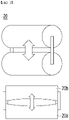
- FIG. 3 shows the shape of the rolling roller 20 by wear.
- the central portion 20a of the roller has a structure which has been further worn compared to both ends 20b of the roller, and in the rolling roller having such a structure, the rolling rate at both ends may be greater than that in the central portion.
- active material particles may be further broken, and it may become vulnerable to moisture by the increase of the specific surface area of the active material particles.
- the region corresponds to both ends in the width direction in the electrode sheet which is wound by the roll for storage of the electrode sheet, and since the moisture penetration from the outside may be easy, moisture vulnerability may be further intensified.
- both ends in the width direction of the electrode sheet may easily contact moisture due to the position, compared to the central portion, and the rolling rate may be relatively high due to the influence of the worn rolling roller, and thus the reaction area between the active material and the moisture increases.
- the reaction between nickel and moisture was minimized at both ends of the electrode sheet by including the positive electrode active material having a particle strength which is relatively strong against the rolling, compared to the central portion.
- the electrode sheet of the present invention has a coated part 100 where the positive electrode active material layer has been applied on at least one surface of the current collector and a non-coated part 200. Further, the coated part 100 is formed of a first positive electrode mixture layer 110 formed on the central portion along the longitudinal direction (y axis) of the electrode sheet, and a second positive electrode mixture layer 120 formed at both ends of the first positive electrode mixture layer 110. Herein, both ends mean both side edges based on the width direction (x axis) of the electrode sheet.
- FIG. 4 illustrates an embodiment in which the second positive electrode mixture layer is formed at both edges of the first positive electrode mixture layer, but not limited thereto, and the second positive electrode mixture layer may be formed at one edge of the first positive electrode mixture layer.
- the particle strength of the positive electrode active material included in the second positive electrode mixture layer is greater than the particle strength of the positive electrode active material in the first positive electrode mixture layer.
- the degree, by which the particles of the second positive electrode mixture layer are broken becomes similar to or smaller than the degree, by which the particles of the first positive electrode mixture layer are broken, and thus the increase of the specific surface area of the active material particles is suppressed, thereby minimizing the reactivity with the moisture.
- the particle strength may be defined as compression breaking strength.
- the positive electrode active material for a secondary battery goes through a rolling process as one of the manufacturing processes.
- the rolling process means pressing an active material layer several times with a predetermined pressure in order to increase density and crystallinity.
- some positive electrode active material particles may be broken by the compression stress.
- the particle strength can be quantified by measuring the force at the point of time when a crack is generated on the particles.
- the particle strength may be a value which is obtained by measuring a point of time when cracks are generated in particles by applying pressure to a positive electrode active material with a force of 0.5 to 10 mN using a micro compression tester and converting a measured result into a value in a pressure unit (MPa).
- the particle strength of the positive electrode active material of the second positive electrode mixture layer may be in a range of 30 to 300 MPa, preferably 40 to 200 MPa, and more preferably 50 to 150 MPa. Further, the particle strength of the positive electrode active material of the first positive electrode mixture layer may be in a range of 30 to 300 MPa, preferably 40 to 200 MPa, and more preferably 50 to 150 MPa, in a range smaller than the particle strength of the positive electrode active material of the second positive electrode mixture layer.
- a ratio B/A of the particle strength B of the positive electrode active material in the second positive electrode mixture layer to the particle strength A of the positive electrode active material in the first positive electrode mixture layer may be in a range of 1 to 2.0, preferably 1.01 to 1.5, and more preferably 1.1 to 1.4.
- the second positive electrode mixture layer contains a mixture of first positive electrode active materials having a relatively large average particle size D 50 and second positive electrode active materials having a relatively small average particle size D 50 .
- second positive electrode active materials of a small particle size are filled in pores formed by first positive electrode active material particles. As such this may become stronger against the same compression stress, compared to the case when formed only first positive electrode active material particles of a large particle size.
- the particle strength of the active material of the second positive electrode mixture layer is greater than the particle strength of the active material of the first positive electrode mixture layer.
- the average particle size D 50 of the first positive electrode active material may be in a range of 9 to 30 ⁇ m, preferably 9 to 25 ⁇ m, and more preferably 10 to 20 ⁇ m
- the average particle size D 50 of the second positive electrode active material may be less than 9 ⁇ m, preferably in a range of 1 to 8 ⁇ m, and more preferably in a range of 2 to 7 ⁇ m.
- the average particle diameter D 50 may be defined as a particle diameter corresponding to 50% of the volume accumulation amount in the particle diameter distribution curve.
- the average particle diameter D 50 may be measured using, for example, a laser diffraction method.
- the ultrasonic waves of about 28 kHz are irradiated with the output of 60 W by introducing a commercially available laser diffraction particle size measuring apparatus (e.g., Microtrac MT 3000), and then the average particle size (D 50 ) corresponding to 50% of the volume accumulation amount in the measuring apparatus may be calculated.
- a commercially available laser diffraction particle size measuring apparatus e.g., Microtrac MT 3000
- positive electrode active materials which are respectively contained in the first positive electrode mixture layer and the second positive electrode mixture layer, independently contain a compound represented by Chemical Formula 1 below: [Chemical formula 1] Li a Ni 1-x-y CO x M1 y M2 w O 2 ,
- composition represented by the chemical Formula 1 When the composition represented by the chemical Formula 1 is used, excellent capacity characteristics may be shown together with excellent structural stability.
- Li in the lithium nickel oxide represented by the above chemical formula 1, Li may be contained by the content corresponding to "a" where 1.0 ⁇ a ⁇ 1.5. If “a” is less than 1.0, the capacity may be lowered, and if it exceeds 1.5, the particles may be sintered in the forming step, and the production of active material may be difficult.
- the Li may be specifically contained by the amount of 1.0 ⁇ a ⁇ 1.2, and more specifically by the amount of 1.0 ⁇ a ⁇ 1.15.
- Ni may be included by the content corresponding to 1-x-y, namely, the content corresponding to 0.6 ⁇ 1-x-y ⁇ 1. If the (1 - x - y) is less than 0.6, the capacity characteristics may be lowered, and if (1 - x - y) is greater than 1, the high temperature stability may be lowered.
- Ni may be contained specifically by the content corresponding to 0.8 ⁇ 1-x-y ⁇ 1, and more specifically by the content corresponding to 0.8 ⁇ 1-x-y ⁇ 0.95.
- M1 may be at least one selected from the group consisting of Al and Mn and may be, more specifically, Al or Mn.
- the M1 may be included in the content corresponding to y in which 0 ⁇ y ⁇ 0.2. If y exceeds 0.2, the output characteristics and capacity characteristics of the battery may be lowered.
- the M1 may be contained specifically by the content corresponding to 0 ⁇ y ⁇ 0.2, and more specifically by the content corresponding to 0.05 ⁇ y ⁇ 0.2.
- elements of Ni, Co and M1 at the lithium nickel oxide indicated by the chemical Formula 1 may be substituted or doped by another element, that is, M2 for improvement of battery characteristics through the distribution adjustment of the metal element in the active material.
- M2 may be one or more selected from a group consisting of Ba, Ca, Zr, Ti, Mg, Ta, Nb and Mo, and more preferably Zr or Ti.
- the element of the M2 may be included within the range which does not lower the characteristics of the positive electrode active material, namely, by the content corresponding to 0 ⁇ w ⁇ 0.1.
- the M2 may be contained by the content corresponding to 0 ⁇ w ⁇ 0.1, and more specifically by the content corresponding to 0 ⁇ w ⁇ 0.02.
- the length of the width of the second positive electrode mixture layer corresponds to 1 to 15%, preferably 2 to 13%, and more preferably 3 to 10% of the length of the width of the first positive electrode mixture layer.
- the width length W2 of the second positive electrode mixture layer may be defined as the sum of the width length W2a of the second positive electrode mixture layer of the left edge of the coated part and the width length W2b of the second positive electrode mixture layer of the right edge of the coated part, and the sum (W2a + W2b) may correspond to 1 to 15% of the width length W1 of the first positive electrode mixture layer.
- the mixing ratio of the first positive electrode active material and the second positive electrode active material may be 95: 5 to 65: 35, preferably 90: 10 to 70: 30, and more preferably 85: 15 to 75: 25, based on the weight. If the rate of the first positive electrode active material is greater than 95%, it is not possible for the second positive electrode active material fully to fill the pores formed by the first positive electrode active material, and if the rate of the second positive electrode active material is greater than 35%, the specific surface area may increase due to the extra second positive electrode active material which remains after filling the pores.
- the second positive electrode mixture layer includes the first positive electrode active material and the second positive electrode active material, and the first positive electrode mixture layer may be formed of positive electrode active materials having the same average particle size D 50 .
- the average particle size D 50 of the positive electrode active material of the first positive electrode mixture layer may be in a range of 9 to 30 ⁇ m, preferably 9 to 25 ⁇ m, and more preferably 10 to 20 ⁇ m. Further, it may be the same as the average particle size of the first positive electrode active material of the second positive electrode mixture layer.
- the second positive electrode mixture layer may include the first positive electrode active material and the second positive electrode active material
- the first positive electrode mixture layer may include a mixture of the first positive electrode active material having a large particle size and the second positive electrode active material having a small particle size as in the second positive electrode mixture layer.
- a ratio (b/a) of a weight (b) of the second positive electrode active material to a weight (a) of the first positive electrode active material in the second positive electrode mixture layer is greater than a ratio (b'/a') of a weight (b') of the second positive electrode active material to a weight (a') of the first positive electrode active material in the first positive electrode mixture layer.
- the ratio, by which the second positive electrode active materials having relatively a small particle size are filled in an empty space in the pore formed by first positive electrode active materials having relatively a large particle size in the second positive electrode mixture layer, is greater than the ratio, by which second positive electrode active materials are fill in an empty space in the pore formed by the first positive electrode active materials in the first positive electrode mixture layer, the second positive electrode mixture layer becomes stronger against rolling than the first positive electrode mixture layer.
- the mixing ratio of particles of the first positive electrode active material having a large particle size and particles of the second positive electrode active material having a small particle size may be in a range of 95: 5 to 65: 35, preferably 90: 10 to 70: 30, and more preferably 85: 15 to 75: 25, based on the weight.
- the average particle size D 50 of the first positive electrode active material contained in the second positive electrode mixture layer may 9 to 30 ⁇ m, preferably 9 to 25 ⁇ m, and more preferably 10 to 20 ⁇ m, and the average particle size D 50 of the second positive electrode active material may be less than 9 ⁇ m, preferably in a range of 1 to 8 ⁇ m, and more preferably 2 to 7 ⁇ m.
- a lithium secondary battery of the present invention includes a positive electrode generated by cutting the coated part and the non-coated part of the electrode sheet according to a shape and a size of a unit electrode.
- the positive electrode includes a positive electrode current collector and a first positive electrode mixture layer and a second positive electrode mixture layer formed on the positive electrode current collector.
- the positive electrode current collector is not particularly limited as long as it has conductivity without causing a chemical change in a battery.
- the positive electrode current collector include stainless steel, aluminum, nickel, titanium, sintered carbon or aluminum or stainless steel of which the surface has been treated with carbon, nickel, titanium, silver, or the like.
- the positive electrode current collector may generally have a thickness of 3 to 500 ⁇ m, and it is possible to increase the adhesive force of the positive electrode active material by forming minute irregularities on the surface of the positive electrode current collector. It may be used as various forms such as a film, a sheet, a foil, a net, a porous body, a foam, and a nonwoven fabric.
- the first positive electrode mixture layer may include a conductive material and a binder together with the above-described positive electrode active material
- the second positive electrode mixture layer may also include a conductive material and a binder together with the above-described positive electrode active material
- the conductive material is used to give conductivity to the electrode, and any conductive material may be used without limitation as long as it has electric conductivity and does not cause a chemical change in the battery.
- the conductive material include: graphite such as natural graphite and artificial graphite; a carbon-based material such as carbon black, acetylene black, ketjen black, channel black, furnace black, lamp black, summer black, or carbon fiber; metal powders or metal fibers such as cooper, nickel, aluminum or silver; conductive whiskey such as zinc oxide and potassium titanate; conductive metal oxides such as titanium oxide; conducting polymers such as polyphenylene derivatives, and one or a mixture thereof may be used.
- the conductive material may generally be included in a 1 to 30% by weight based on the total weight of the positive electrode material layer.
- the binder improves the adhesive force between the positive electrode active material and the positive electrode current collector and attachment between positive electrode active material particles.
- Specific examples include polyvinylidene fluoride (PVDF), vinylidene fluoride-hexafluoropropylene copolymer (PVDF-co-HFP), polyvinyl alcohol, polyacrylonitrile, carboxymethylcellulose (CMC), starch, hydroxypropylcellulose, regenerated cellulose, polyvinylpyrrolidone, polytetrafluoroethylene, polyethylene, polypropylene, ethylenepropylene-diene polymer (EPDM), sulfonated-EPDM, styrene butadiene rubber (SBR), fluororubber, or various copolymers thereof, and one kind or a mixture of two or more kinds of them may be used.
- the binder may be included in a 1 to 30% by weight based on the total weight of the positive electrode material layer.
- the positive electrode may be manufactured according to a general positive electrode manufacturing method except that the first positive electrode mixture layer is applied on the central portion, and the second positive electrode mixture layer is applied on both edges using a dual slot-die coater by using the positive electrode active material, and the composition of the first positive electrode mixture layer and the second positive electrode mixture layer is different. Specifically, it may be manufactured by supplying a positive electrode slurry for formation of a positive electrode mixture layer including the positive electrode active material and selectively a binder and a conductive material to a dual slot-die coater, applying the positive electrode slurry on the positive electrode current collector using the dual slot-die coater, and drying and rolling the positive electrode current collector. At this time, the type and the content of the positive electrode material, the binder, and the conductive material are as described above.
- the solvent of the positive electrode slurry may be a solvent generally used in the art, such as dimethyl sulfoxide (DMSO), isopropyl alcohol, N-methylpyrrolidone (NMP ), acetone, or water, and one of them alone or a mixture of two or more may be used.
- DMSO dimethyl sulfoxide
- NMP N-methylpyrrolidone
- acetone or water, and one of them alone or a mixture of two or more may be used.
- the amount of use of the solvent is sufficient if it can dissolve or disperse the positive electrode active material, the conductive material and the binder in consideration of the application thickness and production yield, and later allow a viscosity for showing an excellent thickness uniformity at the time of application for preparation of a positive electrode.
- the lithium secondary battery includes a positive electrode, a negative electrode facing against the positive electrode, a separator interposed between the positive electrode and the negative electrode, and an electrolyte, and the positive electrode has been described above.
- the lithium secondary battery may selectively further include a battery case for accommodating the electrode assembly of the positive electrode, the negative electrode and the separator, and a sealing member for sealing the battery case.
- the negative electrode current collector is not particularly limited as long as it has high electrical conductivity without causing chemical changes in the battery, and examples thereof include copper, stainless steel, aluminum, nickel, titanium, sintered carbon, copper or stainless steel of which the surface has been treated with carbon, nickel, titanium, silver or the like, aluminum-cadmium alloy, or the like. Further, the negative electrode current collector may generally have a thickness of 3 to 500 ⁇ m, and may strengthen the coupling force of the negative electrode active material by forming minute irregularities on the surface of the current collector as in the positive electrode current collector. It may be used as various forms such as a film, a sheet, a foil, a net, a porous body, a foam, and a nonwoven fabric.
- the negative electrode mixture layer includes a negative electrode active material, and selectively a binder, and a conductive material.
- the negative electrode mixture layer may be manufactured by applying a slurry for forming a negative electrode containing a negative electrode active material and selectively a binder and a conductive material on a negative electrode current collector and drying them, or by casting the slurry for forming the negative electrode on a separate support and then laminating a film, obtained by peeling the slurry from the support on the negative electrode current collector.
- a compound, in which a reversible intercalation and deintercalation of lithium is possible, may be used as the negative electrode active material.
- Specific examples thereof include carbonaceous materials such as artificial graphite, natural graphite, graphitized carbon fiber and amorphous carbon;
- a metal compound capable of alloying with lithium such as Si, Al, Sn, Pb, Zn, Bi, In, Mg, Ga, Cd, Si alloy, Sn alloy or Al alloy;
- Metal oxides such as SiO x (0 ⁇ x ⁇ 2), SnO 2 , vanadium oxide, and lithium vanadium oxide that can dope and dedope lithium; or a composite containing the above-described metallic compound and a carbonaceous material such as a Si-C composite or a Sn-C composite, and any one or a mixture of two or more of them.
- a metal lithium thin film may be used as the negative electrode active material.
- the carbon material both low-crystalline carbon and high-crystalline carbon may be used.
- the low-crystalline carbon include soft carbon and hard carbon.
- the highly crystalline carbon include amorphous, flaky, scaly, spherical or fibrous natural graphite natural graphite or artificial graphite, Kish graphite, pyrolytic carbon, mesophase pitch based carbon fiber, meso-carbon microbeads, mesophase pitches and high-temperature calcined carbon, such as petroleum or coal tar pitch derived cokes.
- binder and the conductive material may be the same as described in the positive electrode previously.
- the separator is used to separate the negative electrode from the positive electrode and provide a moving path of lithium ions
- any separator generally used in a lithium secondary battery may be used without any special limitation.
- a separator having a high electrolyte solution moisturization capability and a low resistance to ion movement of electrolyte solution is preferred.
- porous polymer films for example, porous polymer films made of polyolefin-based polymers such as ethylene homopolymers, propylene homopolymers, ethylene/butene copolymers, ethylene/hexene copolymers and ethylene/methacrylate copolymers, or a laminate of two or more thereof may be used.
- a nonwoven fabric made of a conventional porous nonwoven fabric for example, glass fiber of high melting point, polyethylene terephthalate fiber, or the like may be used.
- a coated separator containing a ceramic component or a polymer material may be used, and may be optionally used as a single layer or a multilayer structure.
- Examples of the electrolyte used in the present invention include an organic liquid electrolyte, an inorganic liquid electrolyte, a solid polymer electrolyte, a gel polymer electrolyte, a solid inorganic electrolyte, and a molten inorganic electrolyte which can be used in the production of a lithium secondary battery, but the present invention is not limited to these examples.
- the electrolyte may include an organic solvent and a lithium salt.
- the organic solvent may be any organic solvent that can act as a medium through which ions involved in an electrochemical reaction of a battery can move.
- examples of the organic solvent include ester solvents such as methyl acetate, ethyl acetate, ⁇ -butyrolactone and ⁇ -caprolactone; ether solvents such as dibutyl ether or tetrahydrofuran; ketone solvents such as cyclohexanone; aromatic hydrocarbon solvents such as benzene and fluorobenzene; carbonate solvents such as dimethyl carbonate (DMC), diethylcarbonate (DEC), methylethylcarbonate (MEC), ethylmethylcarbonate (EMC), ethylene carbonate (EC), and propylene carbonate (PC); alcohol solvents such as ethyl alcohol and isopropyl alcohol; nitriles such as R-CN (R is a straight, branched or cyclic hydrocarbon group of C2 to C20, which may contain
- a carbonate-based solvent is preferable, and a mixture of a cyclic carbonate (for example, ethylene carbonate or propylene carbonate) having a high ionic conductivity and a high dielectric constant which can increase the charge/discharge performance of a battery, and a linear carbonate compound having a low viscosity (for example, ethyl methyl carbonate, dimethyl carbonate or diethyl carbonate) is more preferable.
- a cyclic carbonate for example, ethylene carbonate or propylene carbonate
- a linear carbonate compound having a low viscosity for example, ethyl methyl carbonate, dimethyl carbonate or diethyl carbonate
- the lithium salt can be used without any particular limitation as long as it is a compound capable of providing lithium ions used in a lithium secondary battery. Specifically, LiPF 6 , LiClO 4 , LiAsF 6 , LiBF 4 , LiSbF 6 , LiAl0 4 , LiAlCl 4 , LiCF 3 SO 3 , LiC 4 F 9 SO 3 , LiN(C 2 F 5 SO 3 ) 2 , LiN(C 2 F 5 SO 2 ) 2 , LiN(CF 3 SO 2 ) 2 . LiCl, Lil, or LiB(C 2 O 4 ) 2 may be used as the lithium salt.
- the concentration of the lithium salt is preferably within the range of 0.1 to 2.0M. When the concentration of the lithium salt is within the above range, the electrolyte has an appropriate conductivity and viscosity, so that it can exhibit excellent electrolyte performance and the lithium ions can effectively move.
- the electrolyte may contain one or more additives, such as a haloalkylene carbonate-based compound such as difluoroethylene carbonate, pyridine, triethyl phosphite, triethanolamine, cyclic ether, ethylene diamine, n-glyme, and hexa phosphate triamide, nitrobenzene derivative, sulfur, quinone imine dye, N-substituted oxazolidinone, N, N-substituted imidazolidine, ethylene glycol dialkyl ether, ammonium salt, pyrrole, 2-methoxy ethanol or, aluminum trichloride.
- the additive may be included in an amount of 0.1 wt% to 5 wt% based on the total weight of the electrolyte.
- Lithium secondary batteries including a positive electrode according to the present invention are useful for portable devices such as mobile phones, laptop computers, and digital cameras and electric cars such as hybrid electric vehicles because the lithium secondary batteries stably show excellent discharge capacity, output characteristics, and capacity retention rate.
- a battery module including the lithium secondary battery as a unit cell and a battery pack including the same.
- the battery module or the battery pack may be used as a middle or large size device power source of one or more of a power tool; an electric vehicle including an electric vehicle (EV), a hybrid electric vehicle, and a plug-in hybrid electric vehicle (PHEV); or a system for power storage.
- a power tool including an electric vehicle (EV), a hybrid electric vehicle, and a plug-in hybrid electric vehicle (PHEV)
- PHEV plug-in hybrid electric vehicle
- a method for manufacturing an electrode sheet includes: a slurry manufacturing process of manufacturing a slurry for a first positive electrode mixture and a slurry for a second positive electrode mixture, respectively; an applying process of applying the slurry for the first positive electrode mixture and the slurry for the second positive electrode mixture to thereby form a first positive electrode mixture layer and a second positive electrode mixture layer; a drying process; and a rolling process, wherein in the applying process, the slurry for the first positive electrode mixture has a predetermined width at a central portion of the electrode sheet based on a width direction of the electrode sheet and is applied in a longitudinal direction of the electrode sheet, and the slurry for the second positive electrode mixture has a predetermined width at an edge of one side or both sides of the slurry for the first positive electrode mixture and is applied in a longitudinal direction of the electrode sheet.
- the slurry for the second positive electrode mixture contains a mixture of first positive electrode active materials having a relatively large average particle size D 50 and second positive electrode active materials having a relatively small average particle size D 50 .
- the slurry for the second positive electrode mixture includes a first positive electrode active material having an average particle size D 50 of 9 to 30 ⁇ m, and a second positive electrode active material having an average particle size D 50 of less than 9 ⁇ m.
- the particle strength of the positive electrode active material in the second positive electrode mixture layer may be set to be greater than the particle strength of the positive electrode active material in the first positive electrode mixture layer.
- the mixing ratio of the first positive electrode active material particles having a large particle size and the second positive electrode active material particles having a small particle size is in a range of 95: 5 to 65: 35, preferably 90: 10 to 75: 25, and more preferably 85: 15 to 70: 30.
- the mixing ratio of the first positive electrode active material particles and the second positive electrode active material particles is in the above numerical value range, it is easy to control the particle strength of the positive electrode active material in the second positive electrode mixture layer to be made to be greater than that in the first positive electrode mixture layer.
- the positive electrode active material contained in the slurry for the first positive electrode mixture may be formed of the positive electrode active material having the same average particle size D 50 , or may contain the first positive electrode active material having a relatively large average particle size D 50 , and the second positive electrode active material having a relatively small average particle size D 50 .
- a length of a width of the second positive electrode mixture layer preferably corresponds to 1 to 15% of a length of a width of the first positive electrode mixture layer.
- a first positive electrode active material (D 50 is 11 ⁇ m) containing the nickel content of 80mol% based on the total transition metal as the transition metal oxide of lithium-nickel-cobalt-manganese was prepared, which was then mixed with the carbon black conductive material and PVDF binder at the weight ratio of 96.5: 1.5: 2 in the solvent of N-methyl pyrrolidone, to thereby manufacture a first positive electrode slurry (viscosity: 7000 Pa ⁇ s).
- a positive electrode active material was prepared by mixing a first positive electrode active material (D 50 is 11 ⁇ m), in which the content of nickel corresponds to 80 mol% based on the total transition metal, as a transition metal oxide of lithium-nickel-cobalt-manganese, and a second positive electrode active material (D 50 is 6 ⁇ m), in which the content of nickel corresponds to 80 mol% based on the total transition metal, as a transition metal oxide of lithium-nickel-cobalt-manganese at the ratio of 8: 2, and a carbon black conductive material and a PVDF binder were mixed in N-methylpyrrolidone solvent at the ratio of 96.5: 1.5: 2, to thereby prepare a second positive electrode slurry (viscosity: 7000Pa-s).
- the first positive electrode slurry and the second positive electrode slurry were supplied to the dual slot-die coater, and then the first positive electrode mixture layer and the second positive electrode mixture layer were formed by applying the first positive electrode slurry and the second positive electrode slurry on one surface of the aluminum current collector sheet using the coater.
- the first positive electrode slurry was set to be applied on the coated portion of the slurry coating portion
- the second positive electrode slurry was set to be applied on both edge regions of the coating portion of the first positive electrode slurry.
- the total sum of the width length of the coating portion of the second positive electrode slurry was set to correspond to 8% of the width length of the coating portion of the first positive electrode slurry.
- a positive electrode sheet including a first positive electrode mixture layer and a second positive electrode mixture layer was dried at 130°C, and rolled.
- the prepared positive electrode sheet was wound in the form of a roll, which was then stored in a room temperature of 25°C for 7 days, and then a positive electrode tab was notched in the non-coated part of the positive electrode sheet, and the positive electrode sheet was slitted, to thereby manufacture a positive electrode.
- a porous polyolefin separator was interposed between the positive electrode and lithium metal as the negative electrode, to thereby prepare an electrode assembly, which was then located inside a case, and an electrolyte solution was injected into the case, to thereby manufacture a lithium secondary battery.
- a battery was manufactured in the same method as in example 1 except that the first positive electrode active material and the second positive electrode active material were mixed at the ratio of 85: 15 when preparing a second positive electrode slurry.
- a battery was manufactured in the same method as in example 1 except that the first positive electrode active material and the second positive electrode active material were mixed at the ratio of 75: 25 when preparing a second positive electrode slurry.
- a battery was manufactured in the same manner as in the above example 1, except that the first positive electrode slurry was manufactured as follows.
- a positive electrode active material was prepared by mixing a first positive electrode active material (D 50 is 11 ⁇ m), in which the content of nickel corresponds to 80 mol% based on the total transition metal, as a transition metal oxide of lithium-nickel-cobalt-manganese, and a second positive electrode active material (D 50 is 6 ⁇ m), in which the content of nickel corresponds to 80 mol% based on the total transition metal, as a transition metal oxide of lithium-nickel-cobalt-manganese at the ratio of 9: 1, and a carbon black conductive material and a PVDF binder were mixed in N-methylpyrrolidone solvent at the ratio of 96.5: 1.5: 2, to thereby prepare a first positive electrode slurry (viscosity: 7000Pa-s).
- a slurry for formation of a positive electrode was manufactured in the same manner and with the same materials as in the preparation of the first positive electrode slurry of the example 1.
- a positive electrode mixture layer was formed by applying the slurry for formation of the positive electrode on the aluminum current collector using a single slot-die coater.
- a battery was manufactured in the same manner as in the example 1 except that the first positive electrode slurry and the second positive electrode slurry were prepared as follows.
- a positive electrode active material was prepared by mixing a first positive electrode active material (D 50 is 11 ⁇ m), in which the content of nickel corresponds to 80 mol% based on the total transition metal, as a transition metal oxide of lithium-nickel-cobalt-manganese, and a second positive electrode active material (D 50 is 6 ⁇ m), in which the content of nickel corresponds to 80 mol% based on the total transition metal, as a transition metal oxide of lithium-nickel-cobalt-manganese at the ratio of 7: 3, and a carbon black conductive material and a PVDF binder were mixed in N-methylpyrrolidone solvent at the ratio of 96.5: 1.5: 2, to thereby prepare a first positive electrode slurry (viscosity: 7000Pa-s).
- a positive electrode active material was prepared by mixing a first positive electrode active material (D 50 is 11 ⁇ m), in which the content of nickel corresponds to 80 mol% based on the total transition metal, as a transition metal oxide of lithium-nickel-cobalt-manganese, and a second positive electrode active material (D 50 is 6 ⁇ m), in which the content of nickel corresponds to 80 mol% based on the total transition metal, as a transition metal oxide of lithium-nickel-cobalt-manganese at the ratio of 8: 2, and a carbon black conductive material and a PVDF binder were mixed in N-methylpyrrolidone solvent at the ratio of 96.5: 1.5: 2, to thereby prepare a second positive electrode slurry (viscosity: 7000Pa-s).
- the initial (first) charge/discharge was performed using the electrochemical charge-discharge device for the lithium secondary battery of examples 1 to 4 a comparative examples 1 to 2. At this time, the charge was performed by applying electric current with the current density of 0.33 C-rate until reaching the voltage of 4.2V, and the discharge was performed with the same current density until reaching 2.5V. This charge/discharge was carried out a total of 500 times.
- the capacity of each battery was measured in the charge/discharge process as described above.
- Capacity retention rate % capacity in N cycles/initial capacity ⁇ 100 [Table 1] Is particle strength of active material of second positive electrode mixture layer greater than particle strength of active material of first positive electrode mixture layer? Capacity retention rate in 500 cycles (%) Example 1 O 91.9 Example 2 O 90.6 Example 3 O 91.2 Example 4 O 89.0 Comparati ve Example 1 X 87.5 Comparati ve Example 2 X 87
- the secondary battery according to an embodiment of the present invention has an excellent capacity retention rate compared to the battery in the comparative example. This seems to be possible by suppressing the reactivity of nickel with moisture by differently adjusting the particle strength of each positive electrode active material included in the first positive electrode mixture layer and the second positive electrode mixture layer relatively vulnerable to the moisture exposure in a positive electrode to which the positive electrode active material of the lithium nickel oxide is applied.
Abstract
Description
- This application claims the benefit of priority based on
Korean Patent Application No. 10-2020-0054235 filed on May 7, 2020 Korean Patent Application No. 10-2021-0049862 filed on April 16, 2021 - The present invention relates to an electrode sheet of a positive electrode containing a positive electrode active material having a high content of nickel, and a method of manufacturing the same, and more particularly, to an electrode sheet capable of suppressing reactivity with moisture by applying a slurry for a second positive electrode mixture including a positive electrode active material having a particle strength resistant to rolling at both edge regions of the electrode sheet coated part, to which moisture may be easily permeated during the storage of the electrode sheet, than the central portion of the coated part, and a method of manufacturing the electrode sheet.
- In the lithium secondary battery, in a state that an organic electrolyte solution or a polymer electrolyte solution is charged in a space between a positive electrode and a negative electrode which are made of an active material in which lithium ions may be intercalated and deintercalated, electric energy is generated by oxidation and reduction reactions when lithium ions are intercalated/deintercalated in the positive electrode and the negative electrode.
- Lithium cobalt oxide (LiCoO2), lithium nickel oxide (LiNiO2), lithium manganese oxide (LiMnO2 or LiMn2O4, etc.), lithium iron phosphate compound (LiFePO4) and the like were used as the positive electrode active material of a lithium secondary battery. Further, as a method for improving a low thermal stability while maintaining the excellent reversible capacity of LiNiO2, a lithium composite metal oxide (hereinafter, referred to as "NCM-based lithium composite transition metal oxide"), which was generated by substituting a part of nickel (Ni) with cobalt (CO) and manganese (Mn), was developed. However, the conventional NCM-based lithium composite transition metal oxide was not sufficient in capacity characteristics and thus has a limit in its application.
- In order to improve such a problem, in recent years, research is conducted to increase the content of nickel in the NCM-based lithium composite transition metal oxide. As the content of nickel increases, the energy density per volume increases, but in the case of a high concentration nickel positive electrode active material, there is a problem that the structural stability and the chemical stability of the active material are low, which again rapidly deteriorates the thermal stability. Further, nickel ions react with moisture and carbon dioxide present in the storage environment, and irreversibly switched to NiO, and in this process, lithium ions exit, and lithium byproducts existing in the form of LiOH and Li2CO3 increase. As such, the resistance of the surface of the active material increases, the capacity of the battery decreases, and gas generation during high temperature storage increases.
- Generally, the electrode sheet, which is generated by applying a slurry for an electrode mixture including an electrode active material on a current collector sheet, and then performing a drying and rolling process, is stored in a wound state until punching the electrode for the assembly of a battery.
FIG. 1 shows anelectrode sheet 10 in a wound state for storage. At this time, moisture maybe more easily permeated into the both ends (A) than the central portion of the coated part, based on the width direction (arrow) of the electrode sheet, and thus the moisture content is high in the both ends (A). Therefore, in the case of a positive electrode sheet including a positive electrode active material of the NCM-based lithium composite transition metal oxide, the probability of reaction of nickel with moisture is higher in the both ends than in the central portion. - As such, when manufacturing a high-nickel positive electrode active material electrode having a high content of nickel, in order to relieve moisturization,
Japanese Patent Publication No. 2019-149269 - Therefore, in a positive electrode having a high content of nickel, it is necessary to develop a battery capable of inhibiting reaction of moisture while implementing a high energy density.
- The present invention has been created to solve the above problems, and it is an object of the present invention to provide an electrode sheet in the form that is wound by a roll, capable of mitigating the reaction of the positive electrode active material having a high nickel content with moisture while implementing a high energy density, and a manufacturing method thereof.
- An electrode sheet of the present invention for solving the above problems is an electrode sheet including a non-coated part and a coated part in which a positive electrode mixture layer is applied on at least one surface of a current collector, wherein the coated part includes: a first positive electrode mixture layer configured to be formed on a central portion along a longitudinal direction of the electrode sheet and to contain a positive electrode active material of lithium nickel oxide; and a second positive electrode mixture layer configured to be formed at one or two edges of the first positive electrode mixture layer and to contain a positive electrode active material of lithium nickel oxide, and wherein a particle strength of the positive electrode active material in the second positive electrode mixture layer is greater than a particle strength of the positive electrode active material in the first positive electrode mixture layer.
- In one specific example, a width of the second positive electrode mixture layer corresponds to 1 to 15% of a width of the first positive electrode mixture layer.
- In one specific example, positive electrode active materials, which are respectively contained in the first positive electrode mixture layer and the second positive electrode mixture layer, independently contain a compound represented by Chemical Formula 1 below:
[Chemical formula 1] LiaNi1-x-yCOxM1yM2wO2,
- wherein 1.0≤a≤1.5, 0≤x≤0.2, 0≤y≤0.2, 0≤w≤0.1 and 0≤x+y≤0.4, and
- wherein M1 contains one or two selected from a group consisting of Mn and Al, and M2 contains one or two or more selected from a group consisting of Ba, Ca, Zr, Ti, Mg, Ta, Nb and Mo.
- In one specific example, a ratio B/A of the particle strength B of the positive electrode active material particle in the second positive electrode mixture layer to the particle strength A of the positive electrode active material in the first positive electrode mixture layer is in a range of 1.01 to 1.5.
- In one specific example, the second positive electrode mixture layer contains a mixture of first positive electrode active materials having a relatively large average particle size D50 and second positive electrode active materials having a relatively small average particle size D50.
- In one specific example, the average particle size D50 of the first positive electrode active material is in a range of 9 µm to 30 µm, and the average particle size D50 of the second positive electrode active material is less than 9 µm.
- In one specific example, in the second positive electrode mixture layer, a mixing ratio of the first positive electrode active material and the second positive electrode active material is in a range of 95: 5 to 65: 35 based on a weight.
- In one specific example, the positive electrode active material of the first positive electrode mixture layer may be made of the positive electrode active material having the same average particle size D50.
- At this time, the average particle size D50 of the positive electrode active material of the first positive electrode mixture layer may be in a range of 9 µm to 30 µm.
- In one specific example, the first positive electrode mixture layer may contain a mixture of first positive electrode active materials having a relatively large average particle size D50 and second positive electrode active materials having a relatively small average particle size D50.
- At this time, the average particle size D50 of the first positive electrode active material may be in a range of 9 µm to 30 µm, and the average particle size D50 of the second positive electrode active material may be less than 9 µm.
- At this time, a ratio (b/a) of a weight (b) of the second positive electrode active material to a weight (a) of the first positive electrode active material in the second positive electrode mixture layer is greater than a ratio (b'/a') of a weight (b') of the second positive electrode active material to a weight (a') of the first positive electrode active material in the first positive electrode mixture layer.
- A lithium secondary battery of the present invention includes a positive electrode generated by cutting the coated part and the non-coated part of the electrode sheet according to a shape and a size of a unit electrode.
- A method for manufacturing an electrode sheet according to the present invention includes: a slurry manufacturing process of manufacturing a slurry for a first positive electrode mixture and a slurry for a second positive electrode mixture, respectively; an applying process of applying the slurry for the first positive electrode mixture and the slurry for the second positive electrode mixture to thereby form a first positive electrode mixture layer and a second positive electrode mixture layer; a drying process; and a rolling process, wherein in the applying process, the slurry for the first positive electrode mixture has a predetermined width at a central portion of the electrode sheet based on a width direction of the electrode sheet and is applied in a longitudinal direction of the electrode sheet, and the slurry for the second positive electrode mixture has a predetermined width at an edge of one side or both sides of the slurry for the first positive electrode mixture and is applied in a longitudinal direction of the electrode sheet, and wherein the slurry for the second positive electrode mixture contains a mixture of first positive electrode active materials having a relatively large average particle size D50 and second positive electrode active materials having a relatively small average particle size D50.
- In one specific example, in the applying process, a length of a width of the second positive electrode mixture layer corresponds to 1 to 15% of a length of a width of the first positive electrode mixture layer.
- According to the electrode sheet of the present invention, by including a positive electrode active material having a particle strength, which is greater than that of the first positive electrode mixture layer, in a second positive electrode mixture layer at both edges of the electrode sheet coated part which is easy to be exposed to moisture and where particles may be relatively easily broken due to the rolling roll of a worn structure, the reaction of the second positive electrode mixture layer with moisture after rolling is minimized, thereby improving lifespan characteristics of the battery.
- Further, according to the electrode sheet of the present invention, capacity characteristics of the battery are improved by being applied to a high nickel positive electrode material having a high energy density.
-
-
FIG. 1 is a schematic diagram of an electrode sheet in a wound state. -
FIG. 2 is a graph showing a moisture content in an electrode according to an electrode manufacturing step. -
FIG. 3 is a schematic diagram showing a rolling roller having a wear generated at both ends, according to the increase in the number of times of usage. -
FIG. 4 is a planar schematic diagram illustrating an example of an electrode sheet according to an embodiment of the present invention. -
FIG. 5 is a graph showing results of measuring capacity retention rates according to the charge/discharge cycle for batteries of embodiments and comparative examples. - Hereinafter, the present invention will be described in detail with reference to the drawings. The terms and words used in the present specification and claims should not be construed as limited to ordinary or dictionary terms and the inventor may properly define the concept of the terms in order to best describe its invention. The terms and words should be construed as meaning and concept consistent with the technical idea of the present invention.
- An electrode sheet according to an embodiment of the present invention is an electrode sheet including a non-coated part and a coated part in which a positive electrode mixture layer is applied on at least one surface of a current collector, wherein the coated part includes: a first positive electrode mixture layer configured to be formed on a central portion along a longitudinal direction of the electrode sheet and to contain a positive electrode active material of lithium nickel oxide; and a second positive electrode mixture layer configured to be formed at one or two edges of the first positive electrode mixture layer and to contain a positive electrode active material of lithium nickel oxide, and wherein a particle strength of the positive electrode active material in the second positive electrode mixture layer is greater than a particle strength of the positive electrode active material in the first positive electrode mixture layer.
-
FIG. 2 is a graph showing the moisture content in an electrode according to an electrode manufacturing step. Referring to this, it can be seen that the moisture content in the electrode is increased by a large width in the electrode immediately after the rolling process. This is because, as the electrode is rolled by a large force, the active material particles in the electrode layer are broken, thereby rapidly increasing the specific surface area of the active materials. - Then, the rolling roller for rolling the electrode sheet may show a high rolling rate at both ends of the roller due to the structure, wear, etc.
FIG. 3 shows the shape of therolling roller 20 by wear. Herein, thecentral portion 20a of the roller has a structure which has been further worn compared to bothends 20b of the roller, and in the rolling roller having such a structure, the rolling rate at both ends may be greater than that in the central portion. As such, since more force is applied the region corresponding to both ends of the roller at the electrode sheet than the region corresponding to the central portion of the roller at the time of rolling, active material particles may be further broken, and it may become vulnerable to moisture by the increase of the specific surface area of the active material particles. Further, the region corresponds to both ends in the width direction in the electrode sheet which is wound by the roll for storage of the electrode sheet, and since the moisture penetration from the outside may be easy, moisture vulnerability may be further intensified. - Likewise, both ends in the width direction of the electrode sheet may easily contact moisture due to the position, compared to the central portion, and the rolling rate may be relatively high due to the influence of the worn rolling roller, and thus the reaction area between the active material and the moisture increases. Hence, when preparing a positive electrode or a positive electrode sheet having a high nickel content which is vulnerable to moisture, the reaction between nickel and moisture was minimized at both ends of the electrode sheet by including the positive electrode active material having a particle strength which is relatively strong against the rolling, compared to the central portion.
- Referring to
FIG. 4 , the electrode sheet of the present invention has a coatedpart 100 where the positive electrode active material layer has been applied on at least one surface of the current collector and a non-coatedpart 200. Further, thecoated part 100 is formed of a first positiveelectrode mixture layer 110 formed on the central portion along the longitudinal direction (y axis) of the electrode sheet, and a second positiveelectrode mixture layer 120 formed at both ends of the first positiveelectrode mixture layer 110. Herein, both ends mean both side edges based on the width direction (x axis) of the electrode sheet.FIG. 4 illustrates an embodiment in which the second positive electrode mixture layer is formed at both edges of the first positive electrode mixture layer, but not limited thereto, and the second positive electrode mixture layer may be formed at one edge of the first positive electrode mixture layer. - In the electrode sheet of the present invention, the particle strength of the positive electrode active material included in the second positive electrode mixture layer is greater than the particle strength of the positive electrode active material in the first positive electrode mixture layer. Likewise, by including a positive electrode active material having a relatively large particle strength in the second positive electrode mixture layer, even if the size of the force applied to the second positive electrode mixture layer at the time of rolling by the wear of the rolling roller is greater than the size of the force applied to the first positive electrode mixture layer, the degree, by which the particles of the second positive electrode mixture layer are broken, becomes similar to or smaller than the degree, by which the particles of the first positive electrode mixture layer are broken, and thus the increase of the specific surface area of the active material particles is suppressed, thereby minimizing the reactivity with the moisture.
- In the present invention, the particle strength may be defined as compression breaking strength. The positive electrode active material for a secondary battery goes through a rolling process as one of the manufacturing processes. The rolling process means pressing an active material layer several times with a predetermined pressure in order to increase density and crystallinity. During the rolling process, some positive electrode active material particles may be broken by the compression stress. When force is applied to the positive electrode active material particles, the particle strength can be quantified by measuring the force at the point of time when a crack is generated on the particles. For example, the particle strength may be a value which is obtained by measuring a point of time when cracks are generated in particles by applying pressure to a positive electrode active material with a force of 0.5 to 10 mN using a micro compression tester and converting a measured result into a value in a pressure unit (MPa).
- In one specific example, the particle strength of the positive electrode active material of the second positive electrode mixture layer may be in a range of 30 to 300 MPa, preferably 40 to 200 MPa, and more preferably 50 to 150 MPa. Further, the particle strength of the positive electrode active material of the first positive electrode mixture layer may be in a range of 30 to 300 MPa, preferably 40 to 200 MPa, and more preferably 50 to 150 MPa, in a range smaller than the particle strength of the positive electrode active material of the second positive electrode mixture layer.
- In one specific example, a ratio B/A of the particle strength B of the positive electrode active material in the second positive electrode mixture layer to the particle strength A of the positive electrode active material in the first positive electrode mixture layer may be in a range of 1 to 2.0, preferably 1.01 to 1.5, and more preferably 1.1 to 1.4.
- In one specific example, the second positive electrode mixture layer contains a mixture of first positive electrode active materials having a relatively large average particle size D50 and second positive electrode active materials having a relatively small average particle size D50. In the second positive electrode mixture layer, which is generated by the mixture of positive electrode active materials of a large particle size and a small particle size, second positive electrode active materials of a small particle size are filled in pores formed by first positive electrode active material particles. As such this may become stronger against the same compression stress, compared to the case when formed only first positive electrode active material particles of a large particle size. In the present invention, by applying a blending system of the first positive electrode active material having a large particle size and the second positive electrode active material having a small particle size, to the second positive electrode mixture layer, the particle strength of the active material of the second positive electrode mixture layer is greater than the particle strength of the active material of the first positive electrode mixture layer.
- In one specific example, the average particle size D50 of the first positive electrode active material may be in a range of 9 to 30µm, preferably 9 to 25µm, and more preferably 10 to 20µm, and the average particle size D50 of the second positive electrode active material may be less than 9µm, preferably in a range of 1 to 8µm, and more preferably in a range of 2 to 7µm.
- In the present invention, the average particle diameter D50 may be defined as a particle diameter corresponding to 50% of the volume accumulation amount in the particle diameter distribution curve. The average particle diameter D50 may be measured using, for example, a laser diffraction method. For example, according the method of measuring the average particle size (D50) of the positive electrode active material, after dispersing particles of the positive electrode active material in a dispersion medium, the ultrasonic waves of about 28 kHz are irradiated with the output of 60 W by introducing a commercially available laser diffraction particle size measuring apparatus (e.g., Microtrac MT 3000), and then the average particle size (D50) corresponding to 50% of the volume accumulation amount in the measuring apparatus may be calculated.
- In one specific example, positive electrode active materials, which are respectively contained in the first positive electrode mixture layer and the second positive electrode mixture layer, independently contain a compound represented by
Chemical Formula 1 below:
[Chemical formula 1] LiaNi1-x-yCOxM1yM2wO2,
- wherein 1.0≤a≤1.5, 0≤x≤0.2, 0≤y≤0.2, 0≤w≤0.1 and 0≤x+y≤0.4, and
- wherein M1 contains one or two selected from a group consisting of Mn and Al, and M2 contains one or two or more selected from a group consisting of Ba, Ca, Zr, Ti, Mg, Ta, Nb and Mo.
- When the composition represented by the
chemical Formula 1 is used, excellent capacity characteristics may be shown together with excellent structural stability. - Specifically, in the lithium nickel oxide represented by the
above chemical formula 1, Li may be contained by the content corresponding to "a" where 1.0≤a≤1.5. If "a" is less than 1.0, the capacity may be lowered, and if it exceeds 1.5, the particles may be sintered in the forming step, and the production of active material may be difficult. When considering the significance of the effect of improving the capacity characteristics of the positive electrode active material according to the Li content control and the balance in sinterability at the time of manufacturing the active material, the Li may be specifically contained by the amount of 1.0≤a≤1.2, and more specifically by the amount of 1.0≤a≤1.15. - In the lithium nickel oxide represented by the
chemical formula 1, Ni may be included by the content corresponding to 1-x-y, namely, the content corresponding to 0.6≤1-x-y≤ 1. If the (1 - x - y) is less than 0.6, the capacity characteristics may be lowered, and if (1 - x - y) is greater than 1, the high temperature stability may be lowered. When considering the significance of capacity characteristic improvement effect according to whether Ni is contained, Ni may be contained specifically by the content corresponding to 0.8≤1-x-y<1, and more specifically by the content corresponding to 0.8≤1-x-y<0.95. - In the lithium nickel oxide represented by the
above chemical formula 1, M1 may be at least one selected from the group consisting of Al and Mn and may be, more specifically, Al or Mn. The M1 may be included in the content corresponding to y in which 0≤y≤0.2. If y exceeds 0.2, the output characteristics and capacity characteristics of the battery may be lowered. When considering the significance of the battery characteristic improvement effect according to the inclusion of the M1 element, the M1 may be contained specifically by the content corresponding to 0<y≤0.2, and more specifically by the content corresponding to 0.05≤y≤0.2. - Further, elements of Ni, Co and M1 at the lithium nickel oxide indicated by the
chemical Formula 1 may be substituted or doped by another element, that is, M2 for improvement of battery characteristics through the distribution adjustment of the metal element in the active material. M2 may be one or more selected from a group consisting of Ba, Ca, Zr, Ti, Mg, Ta, Nb and Mo, and more preferably Zr or Ti. The element of the M2 may be included within the range which does not lower the characteristics of the positive electrode active material, namely, by the content corresponding to 0≤w≤0.1. Specifically, the M2 may be contained by the content corresponding to 0<w≤0.1, and more specifically by the content corresponding to 0<w≤0.02. - In one specific example, the length of the width of the second positive electrode mixture layer corresponds to 1 to 15%, preferably 2 to 13%, and more preferably 3 to 10% of the length of the width of the first positive electrode mixture layer. Referring to
FIG. 4 , the width length W2 of the second positive electrode mixture layer may be defined as the sum of the width length W2a of the second positive electrode mixture layer of the left edge of the coated part and the width length W2b of the second positive electrode mixture layer of the right edge of the coated part, and the sum (W2a + W2b) may correspond to 1 to 15% of the width length W1 of the first positive electrode mixture layer. When the width length of the second positive electrode mixture layer satisfies the numerical range, it is preferable in implementing a high energy density while inhibiting the reaction of the nickel in the positive electrode active material with moisture. - In one specific example, in the second positive electrode mixture layer, the mixing ratio of the first positive electrode active material and the second positive electrode active material may be 95: 5 to 65: 35, preferably 90: 10 to 70: 30, and more preferably 85: 15 to 75: 25, based on the weight. If the rate of the first positive electrode active material is greater than 95%, it is not possible for the second positive electrode active material fully to fill the pores formed by the first positive electrode active material, and if the rate of the second positive electrode active material is greater than 35%, the specific surface area may increase due to the extra second positive electrode active material which remains after filling the pores.
- In the electrode sheet according to the first embodiment of the present invention, the second positive electrode mixture layer includes the first positive electrode active material and the second positive electrode active material, and the first positive electrode mixture layer may be formed of positive electrode active materials having the same average particle size D50.
- At this time, the average particle size D50 of the positive electrode active material of the first positive electrode mixture layer may be in a range of 9 to 30µm, preferably 9 to 25µm, and more preferably 10 to 20µm. Further, it may be the same as the average particle size of the first positive electrode active material of the second positive electrode mixture layer.
- In the electrode sheet according to a second embodiment of the present invention, the second positive electrode mixture layer may include the first positive electrode active material and the second positive electrode active material, and the first positive electrode mixture layer may include a mixture of the first positive electrode active material having a large particle size and the second positive electrode active material having a small particle size as in the second positive electrode mixture layer.
- At this time, in order for the second positive electrode mixture layer to become relatively stronger in rolling than the first positive electrode mixture layer, a ratio (b/a) of a weight (b) of the second positive electrode active material to a weight (a) of the first positive electrode active material in the second positive electrode mixture layer is greater than a ratio (b'/a') of a weight (b') of the second positive electrode active material to a weight (a') of the first positive electrode active material in the first positive electrode mixture layer. As designed in this way, since the ratio, by which the second positive electrode active materials having relatively a small particle size are filled in an empty space in the pore formed by first positive electrode active materials having relatively a large particle size in the second positive electrode mixture layer, is greater than the ratio, by which second positive electrode active materials are fill in an empty space in the pore formed by the first positive electrode active materials in the first positive electrode mixture layer, the second positive electrode mixture layer becomes stronger against rolling than the first positive electrode mixture layer.
- At this time, the mixing ratio of particles of the first positive electrode active material having a large particle size and particles of the second positive electrode active material having a small particle size may be in a range of 95: 5 to 65: 35, preferably 90: 10 to 70: 30, and more preferably 85: 15 to 75: 25, based on the weight.
- Further, the average particle size D50 of the first positive electrode active material contained in the second positive electrode mixture layer may 9 to 30µm, preferably 9 to 25µm, and more preferably 10 to 20µm, and the average particle size D50 of the second positive electrode active material may be less than 9µm, preferably in a range of 1 to 8µm, and more preferably 2 to 7µm.
- Hereinafter, a lithium secondary battery of the present invention will be described. A lithium secondary battery of the present invention includes a positive electrode generated by cutting the coated part and the non-coated part of the electrode sheet according to a shape and a size of a unit electrode.
- The positive electrode includes a positive electrode current collector and a first positive electrode mixture layer and a second positive electrode mixture layer formed on the positive electrode current collector.
- The positive electrode current collector is not particularly limited as long as it has conductivity without causing a chemical change in a battery. Examples of the positive electrode current collector include stainless steel, aluminum, nickel, titanium, sintered carbon or aluminum or stainless steel of which the surface has been treated with carbon, nickel, titanium, silver, or the like. Further, the positive electrode current collector may generally have a thickness of 3 to 500µm, and it is possible to increase the adhesive force of the positive electrode active material by forming minute irregularities on the surface of the positive electrode current collector. It may be used as various forms such as a film, a sheet, a foil, a net, a porous body, a foam, and a nonwoven fabric.
- The first positive electrode mixture layer may include a conductive material and a binder together with the above-described positive electrode active material, and the second positive electrode mixture layer may also include a conductive material and a binder together with the above-described positive electrode active material.
- The conductive material is used to give conductivity to the electrode, and any conductive material may be used without limitation as long as it has electric conductivity and does not cause a chemical change in the battery. Some examples of the conductive material include: graphite such as natural graphite and artificial graphite; a carbon-based material such as carbon black, acetylene black, ketjen black, channel black, furnace black, lamp black, summer black, or carbon fiber; metal powders or metal fibers such as cooper, nickel, aluminum or silver; conductive whiskey such as zinc oxide and potassium titanate; conductive metal oxides such as titanium oxide; conducting polymers such as polyphenylene derivatives, and one or a mixture thereof may be used. The conductive material may generally be included in a 1 to 30% by weight based on the total weight of the positive electrode material layer.
- The binder improves the adhesive force between the positive electrode active material and the positive electrode current collector and attachment between positive electrode active material particles. Specific examples include polyvinylidene fluoride (PVDF), vinylidene fluoride-hexafluoropropylene copolymer (PVDF-co-HFP), polyvinyl alcohol, polyacrylonitrile, carboxymethylcellulose (CMC), starch, hydroxypropylcellulose, regenerated cellulose, polyvinylpyrrolidone, polytetrafluoroethylene, polyethylene, polypropylene, ethylenepropylene-diene polymer (EPDM), sulfonated-EPDM, styrene butadiene rubber (SBR), fluororubber, or various copolymers thereof, and one kind or a mixture of two or more kinds of them may be used. The binder may be included in a 1 to 30% by weight based on the total weight of the positive electrode material layer.
- The positive electrode may be manufactured according to a general positive electrode manufacturing method except that the first positive electrode mixture layer is applied on the central portion, and the second positive electrode mixture layer is applied on both edges using a dual slot-die coater by using the positive electrode active material, and the composition of the first positive electrode mixture layer and the second positive electrode mixture layer is different. Specifically, it may be manufactured by supplying a positive electrode slurry for formation of a positive electrode mixture layer including the positive electrode active material and selectively a binder and a conductive material to a dual slot-die coater, applying the positive electrode slurry on the positive electrode current collector using the dual slot-die coater, and drying and rolling the positive electrode current collector. At this time, the type and the content of the positive electrode material, the binder, and the conductive material are as described above.
- The solvent of the positive electrode slurry may be a solvent generally used in the art, such as dimethyl sulfoxide (DMSO), isopropyl alcohol, N-methylpyrrolidone (NMP ), acetone, or water, and one of them alone or a mixture of two or more may be used. The amount of use of the solvent is sufficient if it can dissolve or disperse the positive electrode active material, the conductive material and the binder in consideration of the application thickness and production yield, and later allow a viscosity for showing an excellent thickness uniformity at the time of application for preparation of a positive electrode.
- Specifically, the lithium secondary battery includes a positive electrode, a negative electrode facing against the positive electrode, a separator interposed between the positive electrode and the negative electrode, and an electrolyte, and the positive electrode has been described above. Further, the lithium secondary battery may selectively further include a battery case for accommodating the electrode assembly of the positive electrode, the negative electrode and the separator, and a sealing member for sealing the battery case.
- The negative electrode current collector is not particularly limited as long as it has high electrical conductivity without causing chemical changes in the battery, and examples thereof include copper, stainless steel, aluminum, nickel, titanium, sintered carbon, copper or stainless steel of which the surface has been treated with carbon, nickel, titanium, silver or the like, aluminum-cadmium alloy, or the like. Further, the negative electrode current collector may generally have a thickness of 3 to 500 µm, and may strengthen the coupling force of the negative electrode active material by forming minute irregularities on the surface of the current collector as in the positive electrode current collector. It may be used as various forms such as a film, a sheet, a foil, a net, a porous body, a foam, and a nonwoven fabric.
- The negative electrode mixture layer includes a negative electrode active material, and selectively a binder, and a conductive material. The negative electrode mixture layer may be manufactured by applying a slurry for forming a negative electrode containing a negative electrode active material and selectively a binder and a conductive material on a negative electrode current collector and drying them, or by casting the slurry for forming the negative electrode on a separate support and then laminating a film, obtained by peeling the slurry from the support on the negative electrode current collector.
- A compound, in which a reversible intercalation and deintercalation of lithium is possible, may be used as the negative electrode active material. Specific examples thereof include carbonaceous materials such as artificial graphite, natural graphite, graphitized carbon fiber and amorphous carbon; A metal compound capable of alloying with lithium such as Si, Al, Sn, Pb, Zn, Bi, In, Mg, Ga, Cd, Si alloy, Sn alloy or Al alloy; Metal oxides such as SiOx (0 < x < 2), SnO2, vanadium oxide, and lithium vanadium oxide that can dope and dedope lithium; or a composite containing the above-described metallic compound and a carbonaceous material such as a Si-C composite or a Sn-C composite, and any one or a mixture of two or more of them. In addition, a metal lithium thin film may be used as the negative electrode active material. As the carbon material, both low-crystalline carbon and high-crystalline carbon may be used. Examples of the low-crystalline carbon include soft carbon and hard carbon. Examples of the highly crystalline carbon include amorphous, flaky, scaly, spherical or fibrous natural graphite natural graphite or artificial graphite, Kish graphite, pyrolytic carbon, mesophase pitch based carbon fiber, meso-carbon microbeads, mesophase pitches and high-temperature calcined carbon, such as petroleum or coal tar pitch derived cokes.
- In addition, the binder and the conductive material may be the same as described in the positive electrode previously.
- Meanwhile, in the lithium secondary battery, the separator is used to separate the negative electrode from the positive electrode and provide a moving path of lithium ions, and any separator generally used in a lithium secondary battery may be used without any special limitation. In particular, a separator having a high electrolyte solution moisturization capability and a low resistance to ion movement of electrolyte solution is preferred. Specifically, porous polymer films, for example, porous polymer films made of polyolefin-based polymers such as ethylene homopolymers, propylene homopolymers, ethylene/butene copolymers, ethylene/hexene copolymers and ethylene/methacrylate copolymers, or a laminate of two or more thereof may be used. Further, a nonwoven fabric made of a conventional porous nonwoven fabric, for example, glass fiber of high melting point, polyethylene terephthalate fiber, or the like may be used. In order to secure heat resistance or mechanical strength, a coated separator containing a ceramic component or a polymer material may be used, and may be optionally used as a single layer or a multilayer structure.
- Examples of the electrolyte used in the present invention include an organic liquid electrolyte, an inorganic liquid electrolyte, a solid polymer electrolyte, a gel polymer electrolyte, a solid inorganic electrolyte, and a molten inorganic electrolyte which can be used in the production of a lithium secondary battery, but the present invention is not limited to these examples.
- Specifically, the electrolyte may include an organic solvent and a lithium salt.
- The organic solvent may be any organic solvent that can act as a medium through which ions involved in an electrochemical reaction of a battery can move. Specifically, examples of the organic solvent include ester solvents such as methyl acetate, ethyl acetate, γ-butyrolactone and ε-caprolactone; ether solvents such as dibutyl ether or tetrahydrofuran; ketone solvents such as cyclohexanone; aromatic hydrocarbon solvents such as benzene and fluorobenzene; carbonate solvents such as dimethyl carbonate (DMC), diethylcarbonate (DEC), methylethylcarbonate (MEC), ethylmethylcarbonate (EMC), ethylene carbonate (EC), and propylene carbonate (PC); alcohol solvents such as ethyl alcohol and isopropyl alcohol; nitriles such as R-CN (R is a straight, branched or cyclic hydrocarbon group of C2 to C20, which may contain a double bond aromatic ring or ether bond); amides such as dimethylformamide; dioxolanes such as 1,3-dioxolane; or sulfolane. Among them, a carbonate-based solvent is preferable, and a mixture of a cyclic carbonate (for example, ethylene carbonate or propylene carbonate) having a high ionic conductivity and a high dielectric constant which can increase the charge/discharge performance of a battery, and a linear carbonate compound having a low viscosity (for example, ethyl methyl carbonate, dimethyl carbonate or diethyl carbonate) is more preferable. In this case, when the cyclic carbonate and the chain carbonate are mixed in a volume ratio of about 1: 1 to about 1: 9, the performance of the electrolytic solution may be excellent.
- The lithium salt can be used without any particular limitation as long as it is a compound capable of providing lithium ions used in a lithium secondary battery. Specifically, LiPF6, LiClO4, LiAsF6, LiBF4, LiSbF6, LiAl04, LiAlCl4, LiCF3SO3, LiC4F9SO3, LiN(C2F5SO3)2, LiN(C2F5SO2)2, LiN(CF3SO2)2. LiCl, Lil, or LiB(C2O4)2 may be used as the lithium salt. The concentration of the lithium salt is preferably within the range of 0.1 to 2.0M. When the concentration of the lithium salt is within the above range, the electrolyte has an appropriate conductivity and viscosity, so that it can exhibit excellent electrolyte performance and the lithium ions can effectively move.
- In addition to the electrolyte components, in order to improve the life characteristics of the battery, inhibit the battery capacity reduction, and improve the discharge capacity of the battery, the electrolyte may contain one or more additives, such as a haloalkylene carbonate-based compound such as difluoroethylene carbonate, pyridine, triethyl phosphite, triethanolamine, cyclic ether, ethylene diamine, n-glyme, and hexa phosphate triamide, nitrobenzene derivative, sulfur, quinone imine dye, N-substituted oxazolidinone, N, N-substituted imidazolidine, ethylene glycol dialkyl ether, ammonium salt, pyrrole, 2-methoxy ethanol or, aluminum trichloride. Herein, The additive may be included in an amount of 0.1 wt% to 5 wt% based on the total weight of the electrolyte.
- Lithium secondary batteries including a positive electrode according to the present invention are useful for portable devices such as mobile phones, laptop computers, and digital cameras and electric cars such as hybrid electric vehicles because the lithium secondary batteries stably show excellent discharge capacity, output characteristics, and capacity retention rate.
- According to another embodiment of the present invention, there is provided a battery module including the lithium secondary battery as a unit cell and a battery pack including the same. The battery module or the battery pack may be used as a middle or large size device power source of one or more of a power tool; an electric vehicle including an electric vehicle (EV), a hybrid electric vehicle, and a plug-in hybrid electric vehicle (PHEV); or a system for power storage.
- Hereinafter, a method of manufacturing an electrode sheet according to the present invention will be described.
- A method for manufacturing an electrode sheet according to an embodiment of the present invention includes: a slurry manufacturing process of manufacturing a slurry for a first positive electrode mixture and a slurry for a second positive electrode mixture, respectively; an applying process of applying the slurry for the first positive electrode mixture and the slurry for the second positive electrode mixture to thereby form a first positive electrode mixture layer and a second positive electrode mixture layer; a drying process; and a rolling process, wherein in the applying process, the slurry for the first positive electrode mixture has a predetermined width at a central portion of the electrode sheet based on a width direction of the electrode sheet and is applied in a longitudinal direction of the electrode sheet, and the slurry for the second positive electrode mixture has a predetermined width at an edge of one side or both sides of the slurry for the first positive electrode mixture and is applied in a longitudinal direction of the electrode sheet.
- Herein, the slurry for the second positive electrode mixture contains a mixture of first positive electrode active materials having a relatively large average particle size D50 and second positive electrode active materials having a relatively small average particle size D50.
- Specifically, the slurry for the second positive electrode mixture includes a first positive electrode active material having an average particle size D50 of 9 to 30µm, and a second positive electrode active material having an average particle size D50 of less than 9µm. When manufacturing a slurry for a second positive electrode mixture, by including a first positive electrode active material having a large particle size and a second positive electrode active material having a small particle size, the particle strength of the positive electrode active material in the second positive electrode mixture layer may be set to be greater than the particle strength of the positive electrode active material in the first positive electrode mixture layer.
- In one desirable embodiment, the mixing ratio of the first positive electrode active material particles having a large particle size and the second positive electrode active material particles having a small particle size is in a range of 95: 5 to 65: 35, preferably 90: 10 to 75: 25, and more preferably 85: 15 to 70: 30. When the mixing ratio of the first positive electrode active material particles and the second positive electrode active material particles is in the above numerical value range, it is easy to control the particle strength of the positive electrode active material in the second positive electrode mixture layer to be made to be greater than that in the first positive electrode mixture layer.
- At this time, the positive electrode active material contained in the slurry for the first positive electrode mixture may be formed of the positive electrode active material having the same average particle size D50, or may contain the first positive electrode active material having a relatively large average particle size D50, and the second positive electrode active material having a relatively small average particle size D50.
- In one specific example, in the applying process, a length of a width of the second positive electrode mixture layer preferably corresponds to 1 to 15% of a length of a width of the first positive electrode mixture layer.
- Hereinafter, embodiments of the present invention will be described in detail so that those skilled in the art can easily carry out the present invention. The present invention may, however, be embodied in many different forms and should not be construed as limited to the embodiments set forth herein.
- A first positive electrode active material (D50 is 11 µm) containing the nickel content of 80mol% based on the total transition metal as the transition metal oxide of lithium-nickel-cobalt-manganese was prepared, which was then mixed with the carbon black conductive material and PVDF binder at the weight ratio of 96.5: 1.5: 2 in the solvent of N-methyl pyrrolidone, to thereby manufacture a first positive electrode slurry (viscosity: 7000 Pa·s).
- A positive electrode active material was prepared by mixing a first positive electrode active material (D50 is 11µm), in which the content of nickel corresponds to 80 mol% based on the total transition metal, as a transition metal oxide of lithium-nickel-cobalt-manganese, and a second positive electrode active material (D50 is 6µm), in which the content of nickel corresponds to 80 mol% based on the total transition metal, as a transition metal oxide of lithium-nickel-cobalt-manganese at the ratio of 8: 2, and a carbon black conductive material and a PVDF binder were mixed in N-methylpyrrolidone solvent at the ratio of 96.5: 1.5: 2, to thereby prepare a second positive electrode slurry (viscosity: 7000Pa-s).
- The first positive electrode slurry and the second positive electrode slurry were supplied to the dual slot-die coater, and then the first positive electrode mixture layer and the second positive electrode mixture layer were formed by applying the first positive electrode slurry and the second positive electrode slurry on one surface of the aluminum current collector sheet using the coater. At this time, the first positive electrode slurry was set to be applied on the coated portion of the slurry coating portion, and the second positive electrode slurry was set to be applied on both edge regions of the coating portion of the first positive electrode slurry. The total sum of the width length of the coating portion of the second positive electrode slurry was set to correspond to 8% of the width length of the coating portion of the first positive electrode slurry.
- Thereafter, a positive electrode sheet including a first positive electrode mixture layer and a second positive electrode mixture layer was dried at 130°C, and rolled.
- Likewise, the prepared positive electrode sheet was wound in the form of a roll, which was then stored in a room temperature of 25°C for 7 days, and then a positive electrode tab was notched in the non-coated part of the positive electrode sheet, and the positive electrode sheet was slitted, to thereby manufacture a positive electrode.
- A porous polyolefin separator was interposed between the positive electrode and lithium metal as the negative electrode, to thereby prepare an electrode assembly, which was then located inside a case, and an electrolyte solution was injected into the case, to thereby manufacture a lithium secondary battery. At this time, lithium hexafluorophosphate (LiPF6) of 1.0M concentration was dissolved in an organic solvent consisting of ethylene carbonate/dimethyl carbonate/ethyl methylcarbonate (EC / DMC / EMC volume ratio = 3/ 4/ 3) to manufacture the electrolyte solution.
- A battery was manufactured in the same method as in example 1 except that the first positive electrode active material and the second positive electrode active material were mixed at the ratio of 85: 15 when preparing a second positive electrode slurry.
- A battery was manufactured in the same method as in example 1 except that the first positive electrode active material and the second positive electrode active material were mixed at the ratio of 75: 25 when preparing a second positive electrode slurry.
- A battery was manufactured in the same manner as in the above example 1, except that the first positive electrode slurry was manufactured as follows.
- A positive electrode active material was prepared by mixing a first positive electrode active material (D50 is 11µm), in which the content of nickel corresponds to 80 mol% based on the total transition metal, as a transition metal oxide of lithium-nickel-cobalt-manganese, and a second positive electrode active material (D50 is 6µm), in which the content of nickel corresponds to 80 mol% based on the total transition metal, as a transition metal oxide of lithium-nickel-cobalt-manganese at the ratio of 9: 1, and a carbon black conductive material and a PVDF binder were mixed in N-methylpyrrolidone solvent at the ratio of 96.5: 1.5: 2, to thereby prepare a first positive electrode slurry (viscosity: 7000Pa-s).
- A slurry for formation of a positive electrode was manufactured in the same manner and with the same materials as in the preparation of the first positive electrode slurry of the example 1. A positive electrode mixture layer was formed by applying the slurry for formation of the positive electrode on the aluminum current collector using a single slot-die coater.
- Thereafter, a battery was prepared in the same manner as in Example 1.
- A battery was manufactured in the same manner as in the example 1 except that the first positive electrode slurry and the second positive electrode slurry were prepared as follows.
- A positive electrode active material was prepared by mixing a first positive electrode active material (D50 is 11µm), in which the content of nickel corresponds to 80 mol% based on the total transition metal, as a transition metal oxide of lithium-nickel-cobalt-manganese, and a second positive electrode active material (D50 is 6µm), in which the content of nickel corresponds to 80 mol% based on the total transition metal, as a transition metal oxide of lithium-nickel-cobalt-manganese at the ratio of 7: 3, and a carbon black conductive material and a PVDF binder were mixed in N-methylpyrrolidone solvent at the ratio of 96.5: 1.5: 2, to thereby prepare a first positive electrode slurry (viscosity: 7000Pa-s).
- A positive electrode active material was prepared by mixing a first positive electrode active material (D50 is 11µm), in which the content of nickel corresponds to 80 mol% based on the total transition metal, as a transition metal oxide of lithium-nickel-cobalt-manganese, and a second positive electrode active material (D50 is 6µm), in which the content of nickel corresponds to 80 mol% based on the total transition metal, as a transition metal oxide of lithium-nickel-cobalt-manganese at the ratio of 8: 2, and a carbon black conductive material and a PVDF binder were mixed in N-methylpyrrolidone solvent at the ratio of 96.5: 1.5: 2, to thereby prepare a second positive electrode slurry (viscosity: 7000Pa-s).
- In examples 1 to 4 and comparative examples 1 to 2, the pressure of 100 mN was applied to each of the positive electrode active material in the first positive electrode mixture layer and the positive electrode active material in the second positive electrode mixture layer, for 1 minute, and the force at the time when particles were broken was measured to thereby compare the sizes of the particle strengths. Then the result was shown in Table 1. When the particle strength of the positive electrode active material of the second positive electrode mixture layer was greater than the particle strength of the first positive electrode mixture layer, it was indicated by "O", and when the particle strength of the positive electrode active material of the second positive electrode mixture layer was equal to or smaller than the particle strength of the first positive electrode mixture layer, it was indicated by "X".
- The initial (first) charge/discharge was performed using the electrochemical charge-discharge device for the lithium secondary battery of examples 1 to 4 a comparative examples 1 to 2. At this time, the charge was performed by applying electric current with the current density of 0.33 C-rate until reaching the voltage of 4.2V, and the discharge was performed with the same current density until reaching 2.5V. This charge/discharge was carried out a total of 500 times.
- The capacity of each battery was measured in the charge/discharge process as described above.
- From this, the capacity retention rate of each battery is calculated as follows, and the results are shown in Table 1, and the change in the capacity retention rate according to the cycle is shown in
FIG. 5 .
[Table 1] Is particle strength of active material of second positive electrode mixture layer greater than particle strength of active material of first positive electrode mixture layer? Capacity retention rate in 500 cycles (%) Example 1 O 91.9 Example 2 O 90.6 Example 3 O 91.2 Example 4 O 89.0 Comparati ve Example 1 X 87.5 Comparati ve Example 2 X 87 - Referring to Table 1 and
FIG. 5 , the secondary battery according to an embodiment of the present invention has an excellent capacity retention rate compared to the battery in the comparative example. This seems to be possible by suppressing the reactivity of nickel with moisture by differently adjusting the particle strength of each positive electrode active material included in the first positive electrode mixture layer and the second positive electrode mixture layer relatively vulnerable to the moisture exposure in a positive electrode to which the positive electrode active material of the lithium nickel oxide is applied. - In the above, the present invention has been described in more detail through the drawings and examples. Accordingly, the embodiments described in the specification and the configurations described in the drawings are only the most preferred embodiments of the present invention, and do not represent all of the technical ideas of the present invention. It is to be understood that there may be various equivalents and variations in place of them at the time of filing the present application.
Claims (15)
- An electrode sheet including a non-coated part and a coated part in which a positive electrode mixture layer is applied on at least one surface of a current collector,
wherein the coated part includes:a first positive electrode mixture layer configured to be formed on a central portion along a longitudinal direction of the electrode sheet and to contain a positive electrode active material of lithium nickel oxide; anda second positive electrode mixture layer configured to be formed at one or two edges of the first positive electrode mixture layer and to contain a positive electrode active material of lithium nickel oxide, andwherein a particle strength of the positive electrode active material in the second positive electrode mixture layer is greater than a particle strength of the positive electrode active material in the first positive electrode mixture layer. - The electrode sheet of claim 1, wherein a width of the second positive electrode mixture layer corresponds to 1 to 15% of a width of the first positive electrode mixture layer.
- The electrode sheet of claim 1, wherein positive electrode active materials, which are respectively contained in the first positive electrode mixture layer and the second positive electrode mixture layer, independently contain a compound represented by Chemical Formula 1 below:[Chemical formula 1]LiaNi1-x-yCOxM1yM2wO2,wherein 1.0≤a≤1.5, 0≤x≤0.2, 0≤y≤0.2, 0≤w≤0.1 and 0≤x+y≤0.4, andwherein M1 contains one or two selected from a group consisting of Mn and Al, and M2 contains one or two or more selected from a group consisting of Ba, Ca, Zr, Ti, Mg, Ta, Nb and Mo.
- The electrode sheet of claim 1, wherein a ratio B/A of the particle strength B of the positive electrode active material in the second positive electrode mixture layer to the particle strength A of the positive electrode active material in the first positive electrode mixture layer is in a range of 1.01 to 1.5.
- The electrode sheet of claim 1, wherein the second positive electrode mixture layer contains a mixture of first positive electrode active materials having a relatively large average particle size D50 and second positive electrode active materials having a relatively small average particle size D50.
- The electrode sheet of claim 5, wherein the average particle size D50 of the first positive electrode active material is in a range of 9 µm to 30 µm, and the average particle size D50 of the second positive electrode active material is less than 9 µm.
- The electrode sheet of claim 5, wherein in the second positive electrode mixture layer, a mixing ratio of the first positive electrode active material and the second positive electrode active material is in a range of 95: 5 to 65: 35 based on a weight.
- The electrode sheet of claim 5, wherein the positive electrode active material of the first positive electrode mixture layer is made of the positive electrode active material having the same average particle size D50.
- The electrode sheet of claim 8, wherein the average particle size D50 of the positive electrode active material of the first positive electrode mixture layer is in a range of 9 µm to 30 µm.
- The electrode sheet of claim 7, wherein the first positive electrode mixture layer contains a mixture of first positive electrode active materials having a relatively large average particle size D50 and second positive electrode active materials having a relatively small average particle size D50.
- The electrode sheet of claim 10, wherein a ratio (b/a) of a weight (b) of the second positive electrode active material to a weight (a) of the first positive electrode active material in the second positive electrode mixture layer is greater than a ratio (b'/a') of a weight (b') of the second positive electrode active material to a weight (a') of the first positive electrode active material in the first positive electrode mixture layer.
- The electrode sheet of claim 10, wherein the average particle size D50 of the first positive electrode active material is in a range of 9 µm to 30 µm, and the average particle size D50 of the second positive electrode active material is less than 9 µm.
- A lithium secondary battery including a positive electrode generated by cutting the coated part and the non-coated part of the electrode sheet according to a shape and a size of a unit electrode.
- A method of manufacturing an electrode sheet according to claim 1, the method comprising:a slurry manufacturing process of manufacturing a slurry for a first positive electrode mixture and a slurry for a second positive electrode mixture, respectively;an applying process of applying the slurry for the first positive electrode mixture and the slurry for the second positive electrode mixture to thereby form a first positive electrode mixture layer and a second positive electrode mixture layer;a drying process; anda rolling process,wherein in the applying process, the slurry for the first positive electrode mixture has a predetermined width at a central portion of the electrode sheet based on a width direction of the electrode sheet and is applied in a longitudinal direction of the electrode sheet, and the slurry for the second positive electrode mixture has a predetermined width at an edge of one side or both sides of the slurry for the first positive electrode mixture and is applied in a longitudinal direction of the electrode sheet, andwherein the slurry for the second positive electrode mixture contains a mixture of first positive electrode active materials having a relatively large average particle size D50 and second positive electrode active materials having a relatively small average particle size D50.
- The method of claim 14, wherein in the applying process, a length of a width of the second positive electrode mixture layer corresponds to 1 to 15% of a length of a width of the first positive electrode mixture layer.
Applications Claiming Priority (3)
| Application Number | Priority Date | Filing Date | Title |
|---|---|---|---|
| KR20200054235 | 2020-05-07 | ||
| KR1020210049862A KR20210136842A (en) | 2020-05-07 | 2021-04-16 | High-nickel electrode sheet with reduced reactivity with moisture and a method for manufacturing the same |
| PCT/KR2021/005217 WO2021225316A1 (en) | 2020-05-07 | 2021-04-26 | High-nickel electrode sheet having reduced reactivity with moisture and manufacturing method therefor |
Publications (2)
| Publication Number | Publication Date |
|---|---|
| EP3996168A1 true EP3996168A1 (en) | 2022-05-11 |
| EP3996168A4 EP3996168A4 (en) | 2023-03-01 |
Family
ID=78468083
Family Applications (1)
| Application Number | Title | Priority Date | Filing Date |
|---|---|---|---|
| EP21800583.3A Pending EP3996168A4 (en) | 2020-05-07 | 2021-04-26 | High-nickel electrode sheet having reduced reactivity with moisture and manufacturing method therefor |
Country Status (5)
| Country | Link |
|---|---|
| US (1) | US20220263062A1 (en) |
| EP (1) | EP3996168A4 (en) |
| JP (1) | JP7313536B2 (en) |
| CN (1) | CN114127987A (en) |
| WO (1) | WO2021225316A1 (en) |
Families Citing this family (2)
| Publication number | Priority date | Publication date | Assignee | Title |
|---|---|---|---|---|
| WO2023074427A1 (en) * | 2021-10-28 | 2023-05-04 | 三洋電機株式会社 | Nonaqueous electrolyte secondary battery |
| WO2024071107A1 (en) * | 2022-09-30 | 2024-04-04 | パナソニックエナジー株式会社 | Secondary battery positive electrode, secondary battery, and production method for secondary battery positive electrode |
Family Cites Families (18)
| Publication number | Priority date | Publication date | Assignee | Title |
|---|---|---|---|---|
| CN101662011B (en) * | 2008-08-26 | 2013-05-29 | 比亚迪股份有限公司 | Battery pole piece and preparation method thereof and battery containing same |
| JP2009211956A (en) * | 2008-03-05 | 2009-09-17 | Toyota Motor Corp | Lithium-ion battery |
| JP2010020986A (en) * | 2008-07-09 | 2010-01-28 | Toyota Motor Corp | Electrode plate, battery, vehicle, battery-equipped apparatus, and manufacturing method for electrode plate |
| JP2010080272A (en) * | 2008-09-26 | 2010-04-08 | Panasonic Corp | Method of manufacturing electrode plate for battery |
| JP5858279B2 (en) * | 2011-12-05 | 2016-02-10 | トヨタ自動車株式会社 | Lithium ion secondary battery |
| JP2013246900A (en) * | 2012-05-23 | 2013-12-09 | Toyota Motor Corp | Secondary battery |
| JP5664932B2 (en) * | 2012-10-17 | 2015-02-04 | トヨタ自動車株式会社 | Secondary battery |
| JP5999442B2 (en) * | 2013-04-16 | 2016-09-28 | トヨタ自動車株式会社 | Nonaqueous electrolyte secondary battery |
| JP5991551B2 (en) * | 2014-01-08 | 2016-09-14 | トヨタ自動車株式会社 | Nonaqueous electrolyte secondary battery |
| JP2016001575A (en) * | 2014-06-12 | 2016-01-07 | 株式会社デンソー | Method for manufacturing electrode |
| JP2016115567A (en) * | 2014-12-16 | 2016-06-23 | 日本ゼオン株式会社 | Method of manufacturing electrode for lithium ion battery |
| WO2017057078A1 (en) * | 2015-10-02 | 2017-04-06 | 日立金属株式会社 | Positive electrode material, method for producing same and lithium ion secondary battery |
| KR102012427B1 (en) * | 2015-11-30 | 2019-08-21 | 주식회사 엘지화학 | Positive electrode active material for secondary battery, and positive electrode for secondary battery and secondary battery comprising the same |
| KR102133383B1 (en) * | 2016-03-03 | 2020-07-14 | 주식회사 엘지화학 | Method for manufacturing positive electrode for lithium secondary battery and positive electrode for lithium secondary battery manufactured thereby |
| TWI830706B (en) | 2017-09-14 | 2024-02-01 | 日商可樂麗股份有限公司 | Laminate for protecting polarizing film and method for producing same |
| JP6769451B2 (en) * | 2018-02-27 | 2020-10-14 | トヨタ自動車株式会社 | Lithium ion secondary battery |
| BR112021003447A2 (en) | 2018-08-24 | 2021-05-18 | Nanjing Transthera Biosciences Co., Ltd. | innovative quinoline-derived inhibitor |
| CN109980177B (en) * | 2019-03-29 | 2021-10-22 | 东莞新能安科技有限公司 | Electrode sheet and electrochemical device comprising same |
-
2021
- 2021-04-26 CN CN202180004595.6A patent/CN114127987A/en active Pending
- 2021-04-26 EP EP21800583.3A patent/EP3996168A4/en active Pending
- 2021-04-26 US US17/631,306 patent/US20220263062A1/en active Pending
- 2021-04-26 WO PCT/KR2021/005217 patent/WO2021225316A1/en unknown
- 2021-04-26 JP JP2022503546A patent/JP7313536B2/en active Active
Also Published As
| Publication number | Publication date |
|---|---|
| WO2021225316A1 (en) | 2021-11-11 |
| JP2022542843A (en) | 2022-10-07 |
| CN114127987A (en) | 2022-03-01 |
| JP7313536B2 (en) | 2023-07-24 |
| US20220263062A1 (en) | 2022-08-18 |
| EP3996168A4 (en) | 2023-03-01 |
Similar Documents
| Publication | Publication Date | Title |
|---|---|---|
| KR102359103B1 (en) | Positive electrode active material for secondary battery, method for preparing the same and lithium secondary battery comprising the same | |
| EP3686970B1 (en) | Positive electrode material for secondary battery and lithium secondary battery comprising same | |
| KR102354281B1 (en) | Positive electrode material for lithium secondary battery, positive electrode and lithium secondary battery including the same | |
| KR102417199B1 (en) | Positive electrode active material for secondary battery, method for preparing the same and lithium secondary battery comprising the same | |
| KR102459883B1 (en) | Positive electrode for lithium secondary battery and lithium secondary battery including the same | |
| KR102453274B1 (en) | Positive electrode material for lithium secondary battery, positive electrode and lithium secondary battery including the same | |
| KR102533811B1 (en) | Positive electrode active material for secondary battery, method for manufacturing the same, positive electrode for secondary battery and lithium secondary battery comprising the same | |
| KR102507631B1 (en) | Positive electrode active material for lithium secondary battery, preparing method of the same, positive electrode and lithium secondary battery including the same | |
| KR20190133456A (en) | Positive electrode material for lithium secondary battery, positive electrode for lithium secondary battery and lithium secondary battery comprising the same | |
| KR20210117212A (en) | Positive electrode material for lithium secondary battery, positive electrode and secondary battery | |
| EP4012804A1 (en) | Positive electrode material for secondary battery and lithium secondary battery comprising same | |
| EP3996168A1 (en) | High-nickel electrode sheet having reduced reactivity with moisture and manufacturing method therefor | |
| EP4080615A1 (en) | Positive electrode active material for secondary battery and lithium secondary battery comprising same | |
| EP4047685A1 (en) | Method for producing positive electrode material for secondary battery | |
| EP4002539A1 (en) | Method for manufacturing secondary battery | |
| KR20210071612A (en) | Positive electrode material for lithium secondary battery and preparing method of the same | |
| EP3996169A1 (en) | High-nickel electrode sheet and method for manufacturing same | |
| KR102462952B1 (en) | Positive electrode active material for secondary battery, method for preparing the same and lithium secondary battery comprising the same | |
| KR20210136842A (en) | High-nickel electrode sheet with reduced reactivity with moisture and a method for manufacturing the same | |
| KR102568566B1 (en) | Positive electrode active material for secondary battery, and lithium secondary battery comprising the same | |
| KR20210048436A (en) | Positive electrode active material, positive electrode and lithium secondary battery compring the same | |
| KR20210034984A (en) | Battery system, method for using the same, and battery pack comprising the same | |
| KR102651122B1 (en) | Method for preparing positive electrode active material for lithium secondary battery and positive electrode active material thereby | |
| US20230101947A1 (en) | Positive electrode for lithium secondary battery, and lithium secondary battery | |
| EP4040537B1 (en) | Method for preparing positive electrode active material for lithium secondary battery, and positive electrode active material prepared thereby |
Legal Events
| Date | Code | Title | Description |
|---|---|---|---|
| STAA | Information on the status of an ep patent application or granted ep patent |
Free format text: STATUS: THE INTERNATIONAL PUBLICATION HAS BEEN MADE |
|
| PUAI | Public reference made under article 153(3) epc to a published international application that has entered the european phase |
Free format text: ORIGINAL CODE: 0009012 |
|
| STAA | Information on the status of an ep patent application or granted ep patent |
Free format text: STATUS: REQUEST FOR EXAMINATION WAS MADE |
|
| 17P | Request for examination filed |
Effective date: 20220202 |
|
| AK | Designated contracting states |
Kind code of ref document: A1 Designated state(s): AL AT BE BG CH CY CZ DE DK EE ES FI FR GB GR HR HU IE IS IT LI LT LU LV MC MK MT NL NO PL PT RO RS SE SI SK SM TR |
|
| A4 | Supplementary search report drawn up and despatched |
Effective date: 20230130 |
|
| RIC1 | Information provided on ipc code assigned before grant |
Ipc: H01M 10/052 20100101ALI20230124BHEP Ipc: H01M 4/04 20060101ALI20230124BHEP Ipc: B05C 5/02 20060101ALI20230124BHEP Ipc: H01M 4/505 20100101ALI20230124BHEP Ipc: H01M 4/525 20100101ALI20230124BHEP Ipc: H01M 4/1391 20100101ALI20230124BHEP Ipc: H01M 4/131 20100101AFI20230124BHEP |
|
| DAV | Request for validation of the european patent (deleted) | ||
| DAX | Request for extension of the european patent (deleted) | ||
| REG | Reference to a national code |
Ref country code: DE Ref legal event code: R079 Free format text: PREVIOUS MAIN CLASS: H01M0004131000 Ipc: H01M0010040000 |
|
| RIC1 | Information provided on ipc code assigned before grant |
Ipc: H01M 4/525 20100101ALI20240108BHEP Ipc: H01M 4/1391 20100101ALI20240108BHEP Ipc: H01M 4/131 20100101ALI20240108BHEP Ipc: H01M 10/0525 20100101ALI20240108BHEP Ipc: H01M 10/04 20060101AFI20240108BHEP |
|
| STAA | Information on the status of an ep patent application or granted ep patent |
Free format text: STATUS: EXAMINATION IS IN PROGRESS |
|
| 17Q | First examination report despatched |
Effective date: 20240320 |