EP3995834B1 - Method for determining the wind speed in the rotor plane of a wind turbine - Google Patents
Method for determining the wind speed in the rotor plane of a wind turbine Download PDFInfo
- Publication number
- EP3995834B1 EP3995834B1 EP21204068.7A EP21204068A EP3995834B1 EP 3995834 B1 EP3995834 B1 EP 3995834B1 EP 21204068 A EP21204068 A EP 21204068A EP 3995834 B1 EP3995834 B1 EP 3995834B1
- Authority
- EP
- European Patent Office
- Prior art keywords
- wind turbine
- rotor
- wind
- speed
- plane
- Prior art date
- Legal status (The legal status is an assumption and is not a legal conclusion. Google has not performed a legal analysis and makes no representation as to the accuracy of the status listed.)
- Active
Links
- 238000000034 method Methods 0.000 title claims description 85
- 238000005259 measurement Methods 0.000 claims description 84
- 238000006243 chemical reaction Methods 0.000 claims description 56
- 230000006870 function Effects 0.000 claims description 20
- 238000004422 calculation algorithm Methods 0.000 claims description 11
- 238000000354 decomposition reaction Methods 0.000 claims description 4
- 238000004590 computer program Methods 0.000 claims description 3
- 230000001419 dependent effect Effects 0.000 claims description 3
- 101150037847 MES1 gene Proteins 0.000 claims description 2
- 101100097991 Schizosaccharomyces pombe (strain 972 / ATCC 24843) rar1 gene Proteins 0.000 claims description 2
- 241000940835 Pales Species 0.000 description 18
- 206010033546 Pallor Diseases 0.000 description 18
- 238000010276 construction Methods 0.000 description 13
- 238000012549 training Methods 0.000 description 7
- 230000005540 biological transmission Effects 0.000 description 6
- 239000011159 matrix material Substances 0.000 description 6
- 230000001276 controlling effect Effects 0.000 description 4
- 238000005516 engineering process Methods 0.000 description 4
- 238000012544 monitoring process Methods 0.000 description 4
- 101100228469 Caenorhabditis elegans exp-1 gene Proteins 0.000 description 3
- 230000033228 biological regulation Effects 0.000 description 3
- 238000011084 recovery Methods 0.000 description 3
- 230000001629 suppression Effects 0.000 description 3
- 101150110971 CIN7 gene Proteins 0.000 description 2
- 101100286980 Daucus carota INV2 gene Proteins 0.000 description 2
- 101150110298 INV1 gene Proteins 0.000 description 2
- 241001080024 Telles Species 0.000 description 2
- 101100397044 Xenopus laevis invs-a gene Proteins 0.000 description 2
- 101100397045 Xenopus laevis invs-b gene Proteins 0.000 description 2
- 238000004364 calculation method Methods 0.000 description 2
- 238000001514 detection method Methods 0.000 description 2
- 238000011161 development Methods 0.000 description 2
- 238000003745 diagnosis Methods 0.000 description 2
- 230000005611 electricity Effects 0.000 description 2
- 238000001914 filtration Methods 0.000 description 2
- 230000003116 impacting effect Effects 0.000 description 2
- 238000009434 installation Methods 0.000 description 2
- 238000004519 manufacturing process Methods 0.000 description 2
- 238000012360 testing method Methods 0.000 description 2
- 101100512896 Arabidopsis thaliana MES2 gene Proteins 0.000 description 1
- OKTJSMMVPCPJKN-UHFFFAOYSA-N Carbon Chemical compound [C] OKTJSMMVPCPJKN-UHFFFAOYSA-N 0.000 description 1
- 241000135309 Processus Species 0.000 description 1
- 241000897276 Termes Species 0.000 description 1
- 238000004458 analytical method Methods 0.000 description 1
- 229910052799 carbon Inorganic materials 0.000 description 1
- 210000004027 cell Anatomy 0.000 description 1
- 238000007635 classification algorithm Methods 0.000 description 1
- 238000013461 design Methods 0.000 description 1
- 238000002405 diagnostic procedure Methods 0.000 description 1
- 230000000694 effects Effects 0.000 description 1
- 235000021183 entrée Nutrition 0.000 description 1
- 230000006698 induction Effects 0.000 description 1
- 238000010899 nucleation Methods 0.000 description 1
- 230000003287 optical effect Effects 0.000 description 1
- 238000005457 optimization Methods 0.000 description 1
- 230000001105 regulatory effect Effects 0.000 description 1
- 238000000638 solvent extraction Methods 0.000 description 1
- 230000001131 transforming effect Effects 0.000 description 1
- 238000011144 upstream manufacturing Methods 0.000 description 1
Images


Classifications
-
- G—PHYSICS
- G06—COMPUTING; CALCULATING OR COUNTING
- G06F—ELECTRIC DIGITAL DATA PROCESSING
- G06F30/00—Computer-aided design [CAD]
- G06F30/10—Geometric CAD
- G06F30/17—Mechanical parametric or variational design
-
- F—MECHANICAL ENGINEERING; LIGHTING; HEATING; WEAPONS; BLASTING
- F03—MACHINES OR ENGINES FOR LIQUIDS; WIND, SPRING, OR WEIGHT MOTORS; PRODUCING MECHANICAL POWER OR A REACTIVE PROPULSIVE THRUST, NOT OTHERWISE PROVIDED FOR
- F03D—WIND MOTORS
- F03D7/00—Controlling wind motors
- F03D7/02—Controlling wind motors the wind motors having rotation axis substantially parallel to the air flow entering the rotor
- F03D7/04—Automatic control; Regulation
- F03D7/042—Automatic control; Regulation by means of an electrical or electronic controller
- F03D7/043—Automatic control; Regulation by means of an electrical or electronic controller characterised by the type of control logic
- F03D7/045—Automatic control; Regulation by means of an electrical or electronic controller characterised by the type of control logic with model-based controls
-
- G—PHYSICS
- G01—MEASURING; TESTING
- G01P—MEASURING LINEAR OR ANGULAR SPEED, ACCELERATION, DECELERATION, OR SHOCK; INDICATING PRESENCE, ABSENCE, OR DIRECTION, OF MOVEMENT
- G01P21/00—Testing or calibrating of apparatus or devices covered by the preceding groups
- G01P21/02—Testing or calibrating of apparatus or devices covered by the preceding groups of speedometers
- G01P21/025—Testing or calibrating of apparatus or devices covered by the preceding groups of speedometers for measuring speed of fluids; for measuring speed of bodies relative to fluids
-
- F—MECHANICAL ENGINEERING; LIGHTING; HEATING; WEAPONS; BLASTING
- F03—MACHINES OR ENGINES FOR LIQUIDS; WIND, SPRING, OR WEIGHT MOTORS; PRODUCING MECHANICAL POWER OR A REACTIVE PROPULSIVE THRUST, NOT OTHERWISE PROVIDED FOR
- F03D—WIND MOTORS
- F03D17/00—Monitoring or testing of wind motors, e.g. diagnostics
-
- G—PHYSICS
- G01—MEASURING; TESTING
- G01P—MEASURING LINEAR OR ANGULAR SPEED, ACCELERATION, DECELERATION, OR SHOCK; INDICATING PRESENCE, ABSENCE, OR DIRECTION, OF MOVEMENT
- G01P5/00—Measuring speed of fluids, e.g. of air stream; Measuring speed of bodies relative to fluids, e.g. of ship, of aircraft
- G01P5/02—Measuring speed of fluids, e.g. of air stream; Measuring speed of bodies relative to fluids, e.g. of ship, of aircraft by measuring forces exerted by the fluid on solid bodies, e.g. anemometer
- G01P5/06—Measuring speed of fluids, e.g. of air stream; Measuring speed of bodies relative to fluids, e.g. of ship, of aircraft by measuring forces exerted by the fluid on solid bodies, e.g. anemometer using rotation of vanes
-
- G—PHYSICS
- G06—COMPUTING; CALCULATING OR COUNTING
- G06F—ELECTRIC DIGITAL DATA PROCESSING
- G06F18/00—Pattern recognition
- G06F18/20—Analysing
- G06F18/23—Clustering techniques
-
- G—PHYSICS
- G06—COMPUTING; CALCULATING OR COUNTING
- G06F—ELECTRIC DIGITAL DATA PROCESSING
- G06F30/00—Computer-aided design [CAD]
- G06F30/20—Design optimisation, verification or simulation
- G06F30/28—Design optimisation, verification or simulation using fluid dynamics, e.g. using Navier-Stokes equations or computational fluid dynamics [CFD]
-
- F—MECHANICAL ENGINEERING; LIGHTING; HEATING; WEAPONS; BLASTING
- F05—INDEXING SCHEMES RELATING TO ENGINES OR PUMPS IN VARIOUS SUBCLASSES OF CLASSES F01-F04
- F05B—INDEXING SCHEME RELATING TO WIND, SPRING, WEIGHT, INERTIA OR LIKE MOTORS, TO MACHINES OR ENGINES FOR LIQUIDS COVERED BY SUBCLASSES F03B, F03D AND F03G
- F05B2260/00—Function
- F05B2260/82—Forecasts
- F05B2260/821—Parameter estimation or prediction
-
- F—MECHANICAL ENGINEERING; LIGHTING; HEATING; WEAPONS; BLASTING
- F05—INDEXING SCHEMES RELATING TO ENGINES OR PUMPS IN VARIOUS SUBCLASSES OF CLASSES F01-F04
- F05B—INDEXING SCHEME RELATING TO WIND, SPRING, WEIGHT, INERTIA OR LIKE MOTORS, TO MACHINES OR ENGINES FOR LIQUIDS COVERED BY SUBCLASSES F03B, F03D AND F03G
- F05B2260/00—Function
- F05B2260/84—Modelling or simulation
-
- F—MECHANICAL ENGINEERING; LIGHTING; HEATING; WEAPONS; BLASTING
- F05—INDEXING SCHEMES RELATING TO ENGINES OR PUMPS IN VARIOUS SUBCLASSES OF CLASSES F01-F04
- F05B—INDEXING SCHEME RELATING TO WIND, SPRING, WEIGHT, INERTIA OR LIKE MOTORS, TO MACHINES OR ENGINES FOR LIQUIDS COVERED BY SUBCLASSES F03B, F03D AND F03G
- F05B2270/00—Control
- F05B2270/30—Control parameters, e.g. input parameters
- F05B2270/32—Wind speeds
-
- F—MECHANICAL ENGINEERING; LIGHTING; HEATING; WEAPONS; BLASTING
- F05—INDEXING SCHEMES RELATING TO ENGINES OR PUMPS IN VARIOUS SUBCLASSES OF CLASSES F01-F04
- F05B—INDEXING SCHEME RELATING TO WIND, SPRING, WEIGHT, INERTIA OR LIKE MOTORS, TO MACHINES OR ENGINES FOR LIQUIDS COVERED BY SUBCLASSES F03B, F03D AND F03G
- F05B2270/00—Control
- F05B2270/30—Control parameters, e.g. input parameters
- F05B2270/327—Rotor or generator speeds
-
- F—MECHANICAL ENGINEERING; LIGHTING; HEATING; WEAPONS; BLASTING
- F05—INDEXING SCHEMES RELATING TO ENGINES OR PUMPS IN VARIOUS SUBCLASSES OF CLASSES F01-F04
- F05B—INDEXING SCHEME RELATING TO WIND, SPRING, WEIGHT, INERTIA OR LIKE MOTORS, TO MACHINES OR ENGINES FOR LIQUIDS COVERED BY SUBCLASSES F03B, F03D AND F03G
- F05B2270/00—Control
- F05B2270/30—Control parameters, e.g. input parameters
- F05B2270/328—Blade pitch angle
-
- F—MECHANICAL ENGINEERING; LIGHTING; HEATING; WEAPONS; BLASTING
- F05—INDEXING SCHEMES RELATING TO ENGINES OR PUMPS IN VARIOUS SUBCLASSES OF CLASSES F01-F04
- F05B—INDEXING SCHEME RELATING TO WIND, SPRING, WEIGHT, INERTIA OR LIKE MOTORS, TO MACHINES OR ENGINES FOR LIQUIDS COVERED BY SUBCLASSES F03B, F03D AND F03G
- F05B2270/00—Control
- F05B2270/30—Control parameters, e.g. input parameters
- F05B2270/335—Output power or torque
-
- F—MECHANICAL ENGINEERING; LIGHTING; HEATING; WEAPONS; BLASTING
- F05—INDEXING SCHEMES RELATING TO ENGINES OR PUMPS IN VARIOUS SUBCLASSES OF CLASSES F01-F04
- F05B—INDEXING SCHEME RELATING TO WIND, SPRING, WEIGHT, INERTIA OR LIKE MOTORS, TO MACHINES OR ENGINES FOR LIQUIDS COVERED BY SUBCLASSES F03B, F03D AND F03G
- F05B2270/00—Control
- F05B2270/80—Devices generating input signals, e.g. transducers, sensors, cameras or strain gauges
- F05B2270/804—Optical devices
- F05B2270/8042—Lidar systems
-
- G—PHYSICS
- G01—MEASURING; TESTING
- G01P—MEASURING LINEAR OR ANGULAR SPEED, ACCELERATION, DECELERATION, OR SHOCK; INDICATING PRESENCE, ABSENCE, OR DIRECTION, OF MOVEMENT
- G01P5/00—Measuring speed of fluids, e.g. of air stream; Measuring speed of bodies relative to fluids, e.g. of ship, of aircraft
- G01P5/08—Measuring speed of fluids, e.g. of air stream; Measuring speed of bodies relative to fluids, e.g. of ship, of aircraft by measuring variation of an electric variable directly affected by the flow, e.g. by using dynamo-electric effect
-
- G—PHYSICS
- G01—MEASURING; TESTING
- G01P—MEASURING LINEAR OR ANGULAR SPEED, ACCELERATION, DECELERATION, OR SHOCK; INDICATING PRESENCE, ABSENCE, OR DIRECTION, OF MOVEMENT
- G01P5/00—Measuring speed of fluids, e.g. of air stream; Measuring speed of bodies relative to fluids, e.g. of ship, of aircraft
- G01P5/26—Measuring speed of fluids, e.g. of air stream; Measuring speed of bodies relative to fluids, e.g. of ship, of aircraft by measuring the direct influence of the streaming fluid on the properties of a detecting optical wave
-
- G—PHYSICS
- G01—MEASURING; TESTING
- G01S—RADIO DIRECTION-FINDING; RADIO NAVIGATION; DETERMINING DISTANCE OR VELOCITY BY USE OF RADIO WAVES; LOCATING OR PRESENCE-DETECTING BY USE OF THE REFLECTION OR RERADIATION OF RADIO WAVES; ANALOGOUS ARRANGEMENTS USING OTHER WAVES
- G01S17/00—Systems using the reflection or reradiation of electromagnetic waves other than radio waves, e.g. lidar systems
- G01S17/02—Systems using the reflection of electromagnetic waves other than radio waves
- G01S17/50—Systems of measurement based on relative movement of target
- G01S17/58—Velocity or trajectory determination systems; Sense-of-movement determination systems
-
- G—PHYSICS
- G01—MEASURING; TESTING
- G01S—RADIO DIRECTION-FINDING; RADIO NAVIGATION; DETERMINING DISTANCE OR VELOCITY BY USE OF RADIO WAVES; LOCATING OR PRESENCE-DETECTING BY USE OF THE REFLECTION OR RERADIATION OF RADIO WAVES; ANALOGOUS ARRANGEMENTS USING OTHER WAVES
- G01S17/00—Systems using the reflection or reradiation of electromagnetic waves other than radio waves, e.g. lidar systems
- G01S17/88—Lidar systems specially adapted for specific applications
- G01S17/95—Lidar systems specially adapted for specific applications for meteorological use
-
- G—PHYSICS
- G06—COMPUTING; CALCULATING OR COUNTING
- G06F—ELECTRIC DIGITAL DATA PROCESSING
- G06F2113/00—Details relating to the application field
- G06F2113/06—Wind turbines or wind farms
-
- G—PHYSICS
- G06—COMPUTING; CALCULATING OR COUNTING
- G06F—ELECTRIC DIGITAL DATA PROCESSING
- G06F2113/00—Details relating to the application field
- G06F2113/08—Fluids
-
- G—PHYSICS
- G06—COMPUTING; CALCULATING OR COUNTING
- G06F—ELECTRIC DIGITAL DATA PROCESSING
- G06F2119/00—Details relating to the type or aim of the analysis or the optimisation
- G06F2119/14—Force analysis or force optimisation, e.g. static or dynamic forces
-
- Y—GENERAL TAGGING OF NEW TECHNOLOGICAL DEVELOPMENTS; GENERAL TAGGING OF CROSS-SECTIONAL TECHNOLOGIES SPANNING OVER SEVERAL SECTIONS OF THE IPC; TECHNICAL SUBJECTS COVERED BY FORMER USPC CROSS-REFERENCE ART COLLECTIONS [XRACs] AND DIGESTS
- Y02—TECHNOLOGIES OR APPLICATIONS FOR MITIGATION OR ADAPTATION AGAINST CLIMATE CHANGE
- Y02E—REDUCTION OF GREENHOUSE GAS [GHG] EMISSIONS, RELATED TO ENERGY GENERATION, TRANSMISSION OR DISTRIBUTION
- Y02E10/00—Energy generation through renewable energy sources
- Y02E10/70—Wind energy
- Y02E10/72—Wind turbines with rotation axis in wind direction
Definitions
- the present invention relates to the field of renewable energies and relates more particularly to the measurement of the resource of wind turbines, the wind, for the purposes of wind prediction, control (orientation, torque and speed regulation) and/or diagnosis and /or wind turbine monitoring.
- Wind turbines are designed to produce electricity at the lowest possible price. Therefore, wind turbines are generally built in such a way that they achieve their maximum performance for a wind speed of around 12 m/s. It is not necessary to design wind turbines that maximize their efficiency at higher wind speeds, which are infrequent. In the event of wind speeds above 12 m/s, it is necessary to lose some of the additional energy contained in the wind in order to avoid any damage to the wind turbine. All wind turbines are therefore designed with a power regulation system.
- controllers are designed for variable speed wind turbines.
- the goals of the controllers are to maximize harvested electrical power, minimize rotor speed fluctuations, and minimize fatigue and extreme moments of the structure (blades, mast, and rig).
- the use of an anemometer makes it possible to estimate a wind speed at a point, but this imprecise technology does not make it possible to measure the whole of a wind field or to know the three-dimensional components of the wind speed.
- LiDAR is a remote sensing or optical measurement technology based on the analysis of the properties of a beam sent back to its emitter. This method is used in particular to determine the distance to an object by means of a pulsed laser. Unlike radar based on a similar principle, the LiDAR sensor uses visible or infrared light instead of radio waves. The distance to an object or surface is given by measuring the delay between the pulse and the detection of the reflected signal.
- the LiDAR sensor In the field of wind turbines, the LiDAR sensor is announced as being an essential sensor for the proper functioning of large wind turbines, especially when their size and their power are increasing (today, 5 MW, soon to be 12 MW offshore).
- This sensor allows the remote measurement of the wind, allowing initially to calibrate the wind turbines so that they can provide maximum power (optimization of the power curve).
- the sensor can be positioned on the ground and oriented vertically (profiler), which makes it possible to measure the wind speed and its direction, as well as the wind gradient according to the altitudes.
- This application is particularly critical since it makes it possible to know the energy-producing resource. This is important for wind projects, since it conditions the financial reliability of the project.
- a second application is the placement of this sensor on the nacelle of the wind turbine, to measure the wind field in front of the wind turbine while being oriented almost horizontally.
- the measurement of the wind field in front of the wind turbine makes it possible to know in advance the turbulence that the wind turbine will encounter a few moments later.
- the current techniques for controlling and monitoring a wind turbine do not make it possible to take into account a measurement made by a LiDAR sensor by precisely estimating the speed of the wind at the level of the rotor, that is to say in the plane of the rotor.
- Such an application is described in particular in the patent application EN 3013777 ( US 2015145253 ).
- the LiDAR sensor is an expensive sensor. Moreover, the development of such a LiDAR sensor being relatively recent, it is still difficult to know, by transforming the raw measurements of the LiDAR sensor, how to exploit the characteristics of the wind field such as wind speed, wind direction , wind shear, turbulence, induction factor, etc. Such a LiDAR sensor therefore requires a complex implementation to determine the wind speed in the plane of the rotor. This is why there is a need to determine the speed of the wind in the plane of the rotor inexpensively, reliably and directly usable, for example for controlling and/or diagnosing the wind turbine.
- the object of the present invention is to determine in real time, in an inexpensive manner, without specific instrumentation, and in a reliable manner, the wind speed in the plane of the rotor.
- the present invention relates to a method for determining the speed of the wind in the plane of a rotor of a wind turbine, by means of measurements of the speed of rotation of the rotor, the angle of the blades and the generated power.
- the method according to the invention implements a model of the wind turbine which is constructed from measurements of the speed of the wind, and by means of grouping the measurements, and of regressions.
- said measurements of the wind speed, the speed of rotation of said rotor, the angle of inclination of the blades and the power generated by said machine for converting said wind turbine into at least two classes of operating conditions of the wind turbine by means of a classification method, in particular by means of a k-means algorithm, preferably by means of a k-means ++ algorithm.
- the number of classes is between 3 and 10, preferably between 4 and 7.
- the wind speed in the plane of the rotor is measured based on measurements from a LiDAR sensor.
- the wind speed in the plane of said rotor of said wind turbine is determined in real time by determining the Euclidean distance between said real-time measurements of the speed of rotation of said rotor, the angle of inclination of the blades and the power generated by said conversion machine of said wind turbine and the center of each class, and said model of the wind turbine is applied by a weighted combination of said regressions of each class, the weighting being dependent on said Euclidean distance.
- the wind speed in the plane of said rotor of said wind turbine is predicted for at least one future time step, from said wind turbine model and from said real-time measurements of the rotational speed of said rotor, the angle of inclination of the blades and the power generated by said conversion machine of said wind turbine.
- the invention relates to a computer program product which comprises code instructions arranged to implement the steps of a method according to one of the preceding characteristics, when the program is executed on a control and/or diagnostic unit of said wind turbine.
- the invention relates to a wind turbine which comprises means for measuring the speed of rotation of said rotor, means for measuring the angle of inclination of the blades of the wind turbine, means for measuring the power generated by the conversion machine of said wind turbine, and means for determining the speed of the wind in the plane of the rotor of the wind turbine capable of implementing the method according to one of the preceding characteristics.
- the wind turbine comprises a real-time data acquisition and control system which comprises said means for measuring the speed of rotation of said rotor, said means for measuring the angle of inclination of the blades of the wind turbine, and said means for measuring the power generated by the conversion machine of said wind turbine.
- the present invention relates to a method for determining in real time the wind speed in the rotor plane of a wind turbine, for example the effective wind speed in the rotor plane of a wind turbine.
- the x direction is the longitudinal direction, corresponding to the direction of the rotor axis, upstream of the wind turbine.
- the y direction perpendicular to the x direction, is the lateral direction located in a horizontal plane (the x, y directions form a horizontal plane).
- the z direction is the vertical direction (corresponding substantially to the direction of the mast 4) directed upwards, the z axis is perpendicular to the x and y axes.
- the rotor plane is indicated by the rectangle in dotted lines PR, it is defined by the directions y, z for a zero value of x.
- Steps 2 and 3 are carried out in real time, while step 1 of construction of the wind turbine model is carried out beforehand, only once. These steps can be implemented automatically by computer means, in particular by a controller of a wind turbine, which comprise at least a memory and calculation means. These steps are detailed in the remainder of the description.
- FIG. 2 illustrates, schematically and in a non-limiting manner, the steps of the method according to one embodiment of the invention.
- CON a model of the wind turbine MOD.
- simultaneous measurements LID and MES1 are acquired respectively of the wind speed v mes and the rotational speed of the rotor ⁇ , the angle of inclination of the blades ⁇ and the power generated P g by the machine of wind turbine conversion. From these simultaneous measurements, said measurements are classified into GRO groups. For each grouping, a REG regression is determined between the measurements to construct the wind turbine model MOD.
- measurements MES2 are acquired only of the rotational speed of the rotor ⁇ , of the angle of inclination of the blades ⁇ and of the power generated P g by the machine of wind turbine conversion.
- the constructed model MOD is applied to these measurements to determine, in real time, the speed v of the wind in the plane of the rotor.
- the present invention can be implemented for a determination of the current wind speed (one can then speak of filtering).
- the present invention can be implemented for a prediction of the wind speed for at least one future time step (one can then speak of a prediction).
- a wind turbine model is a model that relates the rotational speed of the rotor, the angle of inclination of the wind turbine blades, the power generated by a wind turbine conversion machine with the wind speed in the plane of the wind turbine rotor.
- this step is implemented only once, beforehand during a model training campaign. Then, in real time, in use of the wind turbine, the constructed wind turbine model is kept, and only steps 2 and 3 are implemented.
- This wind turbine model can be seen as a cartography (from the English "map") of the wind turbine.
- this sub-step we simultaneously measure the wind speed in the plane of the rotor as well as the rotational speed of the rotor, the angle of inclination of the blades of the wind turbine, the power generated by a conversion machine of the wind turbine (in other words the power generated by the wind turbine). All these measurements are used to train the wind turbine model. It may be noted that the wind speed is measured only in this construction stage, indeed, this measurement is not implemented in real time. Thus, in real time, the method according to the invention does not require specific instrumentation. This measurement of the wind speed makes it possible to construct a representative wind turbine model, that is to say which makes it possible to replace the wind speed sensor.
- the wind speed in the plane of the rotor can be measured by means of a sensor placed on the wind turbine, for example a LiDAR sensor.
- a sensor placed on the wind turbine for example a LiDAR sensor.
- the wind speed in the plane of the rotor can be measured by any other means, for example by means of an anemometer or any equivalent sensor.
- a real-time supervisory control and data acquisition (SCADA) system is a large-scale remote management system that can process a large number of remote measurements and to remotely control technical installations. It is an industrial technology in the field of instrumentation, the implementations of which can be considered as instrumentation structures including a middleware type layer. Preferably, all the measurements can be obtained from the SCADA system, which facilitates the implementation of the method without particular instrumentation.
- the SCADA system can make it possible to take into account at least one other measurement to make the determination of the wind speed in the plane of the rotor more precise.
- This may include temperatures, electrical data, vibrations, etc.
- the temperatures can provide information on the effective mechanical losses, and thus make it possible to refine the modeling of the wind turbine.
- Accelerometry associated with a sufficiently fine and accurate modal and vibrational understanding of the structure, can make it possible to trace back to an estimate of the state of the wind and turbulence impacting the wind turbine.
- sub-step 1/a wind speed in the plane of the rotor and speed of rotation of the rotor, power generated and angle of inclination of the blades
- sub-step 1/a wind speed in the plane of the rotor and speed of rotation of the rotor, power generated and angle of inclination of the blades
- clusters also called “clusters” of wind turbine operating conditions.
- the measurements of the two types can be automatically classified by means of a k-means algorithm, preferably a k-means ++ algorithm.
- a k-means algorithm preferably a k-means ++ algorithm.
- Such an algorithm is described in particular in the document: D. Arthur and S. Vassilvitskii, "k-means++: The Advantages of Careful Seeding," Stanford InfoLab, Technical Report 2006-13, June 2006. [Online]. Available: http://ilpubs.stanford.edu:8090/778/ ".
- any other automatic classification algorithm can be used, for example a hierarchical "clustering” algorithm, or a DBSCAN algorithm (from the English: “density-based spatial clustering of applications with noise” which can be translated by spatial classification based on the density of noisy applications), etc.
- the number of groups can be between 3 and 10, preferably between 4 and 7, and can for example be equal to 5. These value ranges make it possible to clearly differentiate the operating conditions of the wind turbine, while limiting the complexity of the construction of the wind turbine model, which could result from a large number of groupings.
- a regression is determined between the simultaneous measurements of sub-step a (wind speed in the plane of the rotor, rotational speed of the rotor, angle d inclination of the blades, and power generated) by a method of decomposition into basic functions and by a method making it possible to establish a relationship between these basic functions and the speed of the wind in the plane of the rotor.
- a Gaussian process regression method and a least squares regression method can be implemented. These regression methods make it possible to link measurements related to the wind turbine (rotor rotation speed, blade inclination angle, power generated) to wind speed.
- the Gaussian process regression method is a nonparametric regression that allows selection of basis functions for the decomposition. Such a Gaussian process regression is flexible, and without over-fitting problems (too many variables and too complex model).
- the least squares regression method is a simple parametric regression to implement, which makes it possible to establish a relationship between the basis functions and the wind speed in the plane of the rotor. Alternatively, it is possible to implement any other regression method making it possible to establish a relationship between these basic functions and the speed of the wind in the plane of the rotor.
- the regression can take into account the previous measurements, preferably, the regression can take into account a number of previous time steps in order to favor the precision of the determination of the wind speed.
- a number r of last measurements of the rotational speed of the rotor, the angle of inclination of the blades, and the power generated by the conversion machine to the wind speed in the plane of the rotor we can relate, a number r of last measurements of the rotational speed of the rotor, the angle of inclination of the blades, and the power generated by the conversion machine to the wind speed in the plane of the rotor .
- we can relate, a number r of last measurements of the rotational speed of the rotor, the angle of inclination of the blades, and the power generated by the conversion machine to the wind speed in the plane of the rotor .
- GPR Gaussian Process Regression
- the next step is to perform the regression. For this, it is possible to select N pairs of measurements (x ih , y i ) from each grouping as training data. The selection of N pairs of measurements makes it possible to accelerate the construction of the wind turbine model with respect to an embodiment for which all the measurements are considered.
- ⁇ ⁇ k ( x ⁇ , X )
- the algorithm estimates ⁇ ⁇ in real time, and the computation time of k ( x ⁇ , X ) is scaled by the size N of the training data. Indeed, the larger N, the longer the computation time.
- a large amount of training data helps to train an accurate wind turbine model that relates the measured data to the wind speed.
- the regression implemented makes it possible to determine the parameters ⁇ And X for each grouping, these parameters are then used by the wind turbine model in real time.
- the wind turbine model is constructed using the regressions determined for each grouping.
- the set of regressions for each grouping makes it possible to determine a wind turbine model.
- At least one of the measurements can be obtained from a real-time control and data acquisition (SCADA) system.
- SCADA real-time supervisory control and data acquisition
- SCADA supervisory control and data acquisition
- all the measurements can be obtained from the SCADA system, which facilitates the implementation of the method without particular instrumentation.
- the SCADA system can make it possible to take into account at least one other measurement to make the determination of the wind speed in the plane of the rotor more precise. This may include temperatures, electrical data, vibrations, etc.
- the temperatures can provide information on the effective mechanical losses, and thus make it possible to refine the modeling of the wind turbine. Accelerometry, associated with a sufficiently fine and accurate modal and vibrational understanding of the structure, can make it possible to trace back to an estimate of the state of the wind and turbulence impacting the wind turbine.
- step 2 we determine, in real time, the wind speed in the plane of the rotor, using the measurements made in step 2 and the model built in step 1. Thus, we obtain a determination of the precise wind speed.
- the current wind speed can be determined.
- the wind speed can be predicted for at least one future time step. For example, one can predict the wind speed for a future time step or for two future time steps.
- the measurements of step 2 can be associated with at least one group determined in sub-step 1/b, and the regression which has been determined for this group is applied to the measurements.
- a regression is applied which corresponds to the same operating conditions of the wind turbine.
- the wind turbine model can be applied using a weighted combination of the regressions from each cluster.
- the weighting implemented in this weighted combination can be dependent on the determined Euclidean distance.
- the measurements of step 2 are associated with at least one group, which corresponds to the same operating conditions of the wind turbine, the determination of the Euclidean distance making it possible to determine the closest group or groups, therefore those which have the same operating conditions of the wind turbine.
- This implementation of the invention can be carried out by means of the following steps:
- C the number of groups of the wind turbine model.
- c i the center of group i, this center is defined from the associated measurements during sub-step 1/b.
- the weighting can be calculated as a function of the Euclidean distance between the considered measurements x ⁇ (for which the wind speed is determined) and the considered grouping.
- N is a free to predetermined parameter, with n>0, the greater the value of n, the less the contributions of the groups distant from the measurements considered are considered.
- Accurate and real-time prediction of the wind speed in the plane of the wind turbine rotor allows suitable control of the wind turbine, in terms of minimizing the effects on the structure of the wind turbine and maximizing the power harvested . Indeed, by means of this control, it is possible to adapt the equipment of the wind turbine so that the wind turbine is in the optimum configuration for this wind.
- the angle of inclination of the blades and/or the electrical recovery torque of the generator of the wind turbine and/or the orientation of the nacelle is controlled as a function of the speed wind and wind direction.
- the individual pitch angle of the blades can be controlled.
- Other types of regulating device can be used. Blade pitch control optimizes energy recovery based on the incident wind on the blades and minimizes structural fatigue.
- the angle of inclination of the blades and/or the electrical recovery torque can be determined by means of maps of the wind turbine as a function of the wind speed at the level of the rotor. For example, one can apply the control method described in the patent application EN 2976630 A1 ( US 2012-0321463 ).
- the monitoring and/or the diagnosis can for example correspond to the mechanical stress undergone by the structure of the wind turbine as a function of the speed of the wind in the plane of the rotor of the wind turbine.
- the invention relates to a computer program product, which comprises code instructions arranged to implement the steps of one of the methods previously described (method for determining the direction of the wind, method of control, diagnostic process).
- the program is executed on a control and/or diagnostic unit of the wind turbine.
- the invention also relates to a wind turbine, in particular an offshore (at sea) or onshore (on land) wind turbine.
- the wind turbine is equipped with means for measuring the rotation of the rotor, means for measuring the angle of inclination of the blades, and means for measuring the power generated by the conversion machine.
- the wind turbine comprises means for determining the speed of the wind in the plane of the rotor capable of implementing the method for determining the wind according to one of the variants or combinations of variants described above.
- the wind turbine may conform to the wind turbine illustrated in figure 1 .
- the wind turbine may comprise a real-time control and data acquisition system (SCADA) which has at least one measuring means among the means for measuring the rotation of the rotor, the means for measuring the angle of inclination of the blades, and the means for measuring the power generated by the conversion machine.
- SCADA real-time control and data acquisition system
- the SCADA system can have all these measures.
- the SCADA system may include additional measurement means (for example temperatures, electrical measurements, etc.) which may make it possible to make the determination of the wind speed in the plane of the rotor more precise.
- the wind turbine may comprise control means, for example the control of the angle of inclination (which can be translated as pitch angle) of at least one blade of the wind turbine or the control of the electric torque, to implement the control method according to the invention.
- the construction of the model of the wind turbine is carried out by means of the effective wind speed in the plane of the rotor measured by means of a LiDAR sensor, these LiDAR measurements being carried out simultaneously with SCADA measurements of the rotation speed of the rotor, the angle of inclination of the blades and the power generated.
- the sample time for SCADA measurements is 1 second, and the sample time for LiDAR sensor data is 0.25 seconds.
Description
La présente invention concerne le domaine des énergies renouvelables et concerne plus particulièrement la mesure de la ressource des éoliennes, le vent, dans des objectifs de prédiction du vent, de contrôle (orientation, régulation de couple et de vitesse) et/ou de diagnostic et/ou de surveillance de l'éolienne.The present invention relates to the field of renewable energies and relates more particularly to the measurement of the resource of wind turbines, the wind, for the purposes of wind prediction, control (orientation, torque and speed regulation) and/or diagnosis and /or wind turbine monitoring.
Une éolienne permet de transformer l'énergie cinétique du vent en énergie électrique ou mécanique. Pour la conversion du vent, elle se compose des éléments suivants :
- un mât permettant de placer un rotor à une hauteur suffisante pour permettre son mouvement (nécessaire pour les éoliennes à axe horizontal) ou de placer ce rotor à une hauteur lui permettant d'être entraîné par un vent plus fort et régulier qu'au niveau du sol. Le mât peut abriter généralement une partie des composants électriques et électroniques (modulateur, commande, multiplicateur, générateur, ...) ;
- une nacelle montée au sommet du mât, abritant des composants mécaniques, pneumatiques, certains composants électriques et électroniques, nécessaires au fonctionnement de l'éolienne. La nacelle peut tourner pour orienter le rotor dans la bonne direction ;
- un rotor, fixé à la nacelle, comprenant plusieurs pales (en général trois) et le nez de l'éolienne. Le rotor est entraîné par l'énergie du vent, il est relié par un arbre mécanique directement ou indirectement (via un système de boîte de vitesse et d'arbre mécanique) à une machine électrique (générateur électrique), ou tout autre type de machine de conversion, qui convertit l'énergie recueillie en énergie électrique ou tout type d'énergie. Le rotor est potentiellement doté de systèmes de contrôle tels que des pales à angle variable ou des freins aérodynamiques ;
- éventuellement une transmission, composée de deux axes (arbre mécanique du rotor et arbre mécanique de la machine de conversion) reliés par une transmission (boite de vitesse) formant ainsi une chaîne cinématique entre l'arbre mécanique du rotor et l'arbre mécanique de la machine de conversion.
- a mast making it possible to place a rotor at a sufficient height to allow its movement (necessary for horizontal axis wind turbines) or to place this rotor at a height allowing it to be driven by a stronger and more regular wind than at the level of the ground. The mast can generally house part of the electrical and electronic components (modulator, control, multiplier, generator, etc.);
- a nacelle mounted at the top of the mast, housing the mechanical and pneumatic components, certain electrical and electronic components, necessary for the operation of the wind turbine. The nacelle can rotate to point the rotor in the right direction;
- a rotor, fixed to the nacelle, comprising several blades (usually three) and the nose of the wind turbine. The rotor is driven by the energy of the wind, it is connected by a mechanical shaft directly or indirectly (via a gearbox and mechanical shaft system) to an electric machine (electric generator), or any other type of machine converter, which converts the collected energy into electrical energy or any type of energy. The rotor is potentially equipped with control systems such as variable angle blades or aerodynamic brakes;
- possibly a transmission, composed of two axes (mechanical shaft of the rotor and mechanical shaft of the conversion machine) connected by a transmission (gearbox) thus forming a kinematic chain between the mechanical shaft of the rotor and the mechanical shaft of the converting machine.
Depuis le début des années 1990, l'énergie éolienne a connu un regain d'intérêt, en particulier dans l'Union Européenne où le taux de croissance annuel est d'environ 20 %. Cette croissance est attribuée à la possibilité inhérente de production d'électricité sans émissions de carbone. Afin de soutenir cette croissance, le rendement des éoliennes doit continuer à être amélioré. La perspective d'augmentation de production d'énergie éolienne nécessite le développement d'outils de production efficaces, et d'outils de contrôle avancé pour améliorer les performances des machines. Les éoliennes sont conçues pour produire de l'électricité à un prix aussi bas que possible. Par conséquent, les éoliennes sont en général construites de manière à atteindre leur performance maximale pour une vitesse du vent d'environ 12 m/s. Il n'est pas nécessaire de concevoir des éoliennes qui maximisent leur rendement à des vitesses de vent plus élevées, celles-ci étant peu fréquentes. En cas de vitesses de vent supérieures à 12 m/s, il est nécessaire de perdre une partie de l'énergie supplémentaire contenue dans le vent afin d'éviter tout endommagement de l'éolienne. Toutes les éoliennes sont donc conçues avec un système de régulation de la puissance.Since the early 1990s, wind energy has experienced renewed interest, particularly in the European Union where the annual growth rate is around 20%. This growth is attributed to the inherent possibility of generating electricity without carbon emissions. In order to support this growth, the performance of wind turbines must continue to be improved. The prospect of increasing wind energy production requires the development of efficient production tools, and advanced control tools to improve machine performance. Wind turbines are designed to produce electricity at the lowest possible price. Therefore, wind turbines are generally built in such a way that they achieve their maximum performance for a wind speed of around 12 m/s. It is not necessary to design wind turbines that maximize their efficiency at higher wind speeds, which are infrequent. In the event of wind speeds above 12 m/s, it is necessary to lose some of the additional energy contained in the wind in order to avoid any damage to the wind turbine. All wind turbines are therefore designed with a power regulation system.
Pour cette régulation de la puissance, des contrôleurs sont conçus pour des éoliennes à vitesse variable. Les objectifs des contrôleurs sont de maximiser la puissance électrique récupérée, de minimiser les fluctuations de vitesse du rotor et de minimiser la fatigue et les moments extrêmes de la structure (pales, mât et plate-forme).For this power regulation, controllers are designed for variable speed wind turbines. The goals of the controllers are to maximize harvested electrical power, minimize rotor speed fluctuations, and minimize fatigue and extreme moments of the structure (blades, mast, and rig).
Pour optimiser le contrôle, il est important de connaître la vitesse du vent au niveau du rotor de l'éolienne. Pour cela, différentes techniques ont été mises au point.To optimize control, it is important to know the wind speed at the wind turbine rotor. For this, different techniques have been developed.
Selon une première technique, l'utilisation d'un anémomètre permet d'estimer une vitesse du vent en un point, mais cette technologie imprécise ne permet pas de mesurer l'ensemble d'un champ de vent ou de connaître les composantes tridimensionnelles de la vitesse du vent.According to a first technique, the use of an anemometer makes it possible to estimate a wind speed at a point, but this imprecise technology does not make it possible to measure the whole of a wind field or to know the three-dimensional components of the wind speed.
Selon une deuxième technique, on peut utiliser un capteur LiDAR (acronyme de l'expression en langue anglaise « light détection and ranging » pouvant être traduite par télédétection par Laser). Le LiDAR est une technologie de télédétection ou de mesure optique basée sur l'analyse des propriétés d'un faisceau renvoyé vers son émetteur. Cette méthode est utilisée notamment pour déterminer la distance à un objet au moyen d'un laser à impulsions. À la différence du radar basé sur un principe similaire, le capteur LiDAR utilise de la lumière visible ou infrarouge au lieu d'ondes radio. La distance à un objet ou à une surface est donnée par la mesure du délai entre l'impulsion et la détection du signal réfléchi.According to a second technique, it is possible to use a LiDAR sensor (acronym of the expression in English “light detection and ranging” which can be translated by remote sensing by Laser). LiDAR is a remote sensing or optical measurement technology based on the analysis of the properties of a beam sent back to its emitter. This method is used in particular to determine the distance to an object by means of a pulsed laser. Unlike radar based on a similar principle, the LiDAR sensor uses visible or infrared light instead of radio waves. The distance to an object or surface is given by measuring the delay between the pulse and the detection of the reflected signal.
Dans le domaine des éoliennes, le capteur LiDAR est annoncé comme étant un capteur indispensable au bon fonctionnement des grandes éoliennes, tout particulièrement alors que leur taille et leur puissance augmente (aujourd'hui, 5 MW, bientôt 12 MW en offshore). Ce capteur permet la mesure à distance du vent, permettant dans un premier temps de calibrer les éoliennes pour qu'elles puissent fournir une puissance maximale (optimisation de la courbe de puissance). Pour cette étape de calibration, le capteur peut être positionné au sol et orienté verticalement (profiler), ce qui permet de mesurer la vitesse de vent et sa direction, ainsi que le gradient de vent selon les altitudes. Cette application est tout particulièrement critique puisqu'elle permet de connaître la ressource productrice d'énergie. Ceci est important pour les projets éoliens, puisque cela conditionne la fiabilité financière du projet. Une seconde application est le placement de ce capteur sur la nacelle de l'éolienne, pour mesurer le champ de vent en avant de l'éolienne en étant orienté quasiment horizontalement. A priori, la mesure du champ de vent à l'avant de l'éolienne permet de connaître à l'avance la turbulence que va rencontrer l'éolienne quelques instants plus tard. Toutefois, les techniques actuelles de contrôle et de surveillance d'une éolienne ne permettent pas de prendre en compte une mesure réalisée par un capteur LiDAR en estimant précisément la vitesse du vent au niveau du rotor, c'est-à-dire dans le plan du rotor. Une telle application est décrite notamment dans la demande de brevet
Toutefois, le capteur LiDAR est un capteur onéreux. De plus, le développement d'un tel capteur LiDAR étant relativement récent, il est encore difficile de savoir, en transformant les mesures brutes du capteur LiDAR, comment exploiter les caractéristiques du champ de vent telles que la vitesse du vent, la direction du vent, le cisaillement du vent, la turbulence, le facteur d'induction, etc. Un tel capteur LiDAR nécessite donc une mise en oeuvre complexe pour déterminer la vitesse du vent dans le plan du rotor. C'est pourquoi, il existe un besoin de déterminer la vitesse du vent dans le plan du rotor de manière peu onéreuse, de manière fiable, et directement exploitable, par exemple pour le contrôle et/ou le diagnostic de l'éolienne.However, the LiDAR sensor is an expensive sensor. Moreover, the development of such a LiDAR sensor being relatively recent, it is still difficult to know, by transforming the raw measurements of the LiDAR sensor, how to exploit the characteristics of the wind field such as wind speed, wind direction , wind shear, turbulence, induction factor, etc. Such a LiDAR sensor therefore requires a complex implementation to determine the wind speed in the plane of the rotor. This is why there is a need to determine the speed of the wind in the plane of the rotor inexpensively, reliably and directly usable, for example for controlling and/or diagnosing the wind turbine.
Les documents
La présente invention a pour but de déterminer en temps réel, de manière peu onéreuse, sans instrumentation spécifique, et de manière fiable, la vitesse de vent dans le plan du rotor. Dans ce but, la présente invention concerne un procédé de détermination de la vitesse du vent dans le plan d'un rotor d'une éolienne, au moyen de mesures de la vitesse de rotation du rotor, de l'angle des pales et de la puissance générée. Le procédé selon l'invention met en oeuvre un modèle de l'éolienne qui est construit à partir de mesures de la vitesse du vent, et au moyen de regroupement des mesures, et de régressions. Ainsi, une fois le modèle d'éolienne construit, on peut appliquer, en temps réel, de manière fiable, et sans instrumentation spécifique, ce modèle pour déterminer la vitesse du vent dans le plan du rotor à partir de mesures de la vitesse de rotation du rotor, de l'angle des pales et de la puissance électrique générée.The object of the present invention is to determine in real time, in an inexpensive manner, without specific instrumentation, and in a reliable manner, the wind speed in the plane of the rotor. For this purpose, the present invention relates to a method for determining the speed of the wind in the plane of a rotor of a wind turbine, by means of measurements of the speed of rotation of the rotor, the angle of the blades and the generated power. The method according to the invention implements a model of the wind turbine which is constructed from measurements of the speed of the wind, and by means of grouping the measurements, and of regressions. Thus, a Once the wind turbine model has been built, it is possible to apply, in real time, reliably, and without specific instrumentation, this model to determine the wind speed in the plane of the rotor from measurements of the rotational speed of the rotor, the angle of the blades and the electrical power generated.
L'invention concerne un procédé de détermination d'une vitesse du vent dans le plan d'un rotor d'une éolienne, dans lequel on met en oeuvre les étapes suivantes :
- a. On construit un modèle d'éolienne qui relie la vitesse de rotation dudit rotor de ladite éolienne, l'angle de l'inclinaison des pales de ladite éolienne, et la puissance générée par une machine de conversion de l'éolienne à la vitesse du vent dans le plan du rotor de ladite éolienne au moyen des étapes suivantes :
- i. On mesure simultanément la vitesse du vent dans le plan du rotor de ladite éolienne ainsi que la vitesse de rotation dudit rotor, l'angle d'inclinaison des pales et la puissance générée par ladite machine de conversion de ladite éolienne ;
- ii. On classe lesdites mesures simultanées de la vitesse du vent dans le plan du rotor de ladite éolienne ainsi que de la vitesse de rotation dudit rotor, de l'angle d'inclinaison des pales et de la puissance générée par ladite machine de conversion de ladite éolienne en au moins deux classes de conditions de fonctionnement de l'éolienne ;
- iii. Pour chaque classe, on détermine une régression entre les mesures de la vitesse du vent dans le plan du rotor de ladite éolienne ainsi que la vitesse de rotation dudit rotor, l'angle d'inclinaison des pales et la puissance générée par ladite machine de conversion de ladite éolienne par une méthode de décomposition en fonctions de base, et par une méthode permettant d'établir une relation entre ces fonctions de base et la vitesse du vent dans le plan du rotor, de préférence au moyen d'une méthode de régression par processus gaussien et par une méthode de régression par les moindres carrés ;
- iv. On construit ledit modèle de ladite éolienne au moyen desdites régressions déterminées pour chaque classe ;
- b. On mesure, en temps réel, la vitesse de rotation dudit rotor, l'angle d'inclinaison des pales et la puissance générée par ladite machine de conversion de ladite éolienne ; et
- c. On détermine, en temps réel, la vitesse du vent dans le plan dudit rotor de ladite éolienne au moyen desdites mesures en temps réel de la vitesse de rotation dudit rotor, de l'angle d'inclinaison des pales et de la puissance générée par ladite machine de conversion de ladite éolienne et dudit modèle d'éolienne.
- has. A wind turbine model is constructed which relates the rotational speed of said rotor of said wind turbine, the angle of inclination of the blades of said wind turbine, and the power generated by a wind turbine conversion machine to the wind speed in the plane of the rotor of said wind turbine by means of the following steps:
- i. Simultaneously measuring the wind speed in the plane of the rotor of said wind turbine as well as the speed of rotation of said rotor, the angle of inclination of the blades and the power generated by said conversion machine of said wind turbine;
- ii. Said simultaneous measurements of the wind speed in the plane of the rotor of said wind turbine as well as the speed of rotation of said rotor, the angle of inclination of the blades and the power generated by said conversion machine of said wind turbine are classified in at least two classes of operating conditions of the wind turbine;
- iii. For each class, a regression is determined between the measurements of the wind speed in the plane of the rotor of said wind turbine as well as the speed of rotation of said rotor, the angle of inclination of the blades and the power generated by said conversion machine of said wind turbine by a method of decomposition into basis functions, and by a method making it possible to establish a relationship between these basis functions and the wind speed in the plane of the rotor, preferably by means of a regression method by Gaussian process and by a least squares regression method;
- iv. Said model of said wind turbine is constructed by means of said regressions determined for each class;
- b. The speed of rotation of said rotor, the angle of inclination of the blades and the power generated by said conversion machine of said wind turbine are measured in real time; And
- vs. The wind speed in the plane of said rotor of said wind turbine is determined in real time by means of said real-time measurements of the speed of rotation of said rotor, the angle of inclination of the blades and the power generated by said conversion machine of said wind turbine and of said wind turbine model.
Selon un mode de réalisation, on classe lesdites mesures de la vitesse du vent, de la vitesse de rotation dudit rotor, de l'angle d'inclinaison des pales et de la puissance générée par ladite machine de conversion de ladite éolienne en au moins deux classes de conditions de fonctionnement de l'éolienne au moyen d'une méthode de classification, notamment au moyen d'un algorithme du k-means, de préférence au moyen d'un algorithme du k-means ++.According to one embodiment, said measurements of the wind speed, the speed of rotation of said rotor, the angle of inclination of the blades and the power generated by said machine for converting said wind turbine into at least two classes of operating conditions of the wind turbine by means of a classification method, in particular by means of a k-means algorithm, preferably by means of a k-means ++ algorithm.
Avantageusement, le nombre de classes est compris entre 3 et 10, de préférence entre 4 et 7.Advantageously, the number of classes is between 3 and 10, preferably between 4 and 7.
Conformément à une mise en oeuvre, on mesure la vitesse du vent dans le plan du rotor sur la base de mesures d'un capteur LiDAR.According to one implementation, the wind speed in the plane of the rotor is measured based on measurements from a LiDAR sensor.
Selon un aspect, on détermine, en temps réel, la vitesse de vent dans le plan dudit rotor de ladite éolienne en déterminant la distance euclidienne entre lesdites mesures en temps réel de la vitesse de rotation dudit rotor, de l'angle d'inclinaison des pales et de la puissance générée par ladite machine de conversion de ladite éolienne et le centre de chaque classe, et on applique ledit modèle de l'éolienne par une combinaison pondérée desdites régressions de chaque classe, la pondération étant dépendante de ladite distance euclidienne.According to one aspect, the wind speed in the plane of said rotor of said wind turbine is determined in real time by determining the Euclidean distance between said real-time measurements of the speed of rotation of said rotor, the angle of inclination of the blades and the power generated by said conversion machine of said wind turbine and the center of each class, and said model of the wind turbine is applied by a weighted combination of said regressions of each class, the weighting being dependent on said Euclidean distance.
Selon une option de réalisation, on prédit la vitesse du vent dans le plan dudit rotor de ladite éolienne pour au moins un pas de temps futur, à partir dudit modèle d'éolienne et desdites mesures en temps réel de la vitesse de rotation dudit rotor, de l'angle d'inclinaison des pales et de la puissance générée par ladite machine de conversion de ladite éolienne.According to one embodiment option, the wind speed in the plane of said rotor of said wind turbine is predicted for at least one future time step, from said wind turbine model and from said real-time measurements of the rotational speed of said rotor, the angle of inclination of the blades and the power generated by said conversion machine of said wind turbine.
L'invention concerne en outre une procédé de contrôle d'une éolienne. Pour ce procédé, on met en oeuvre les étapes suivantes :
- a. on détermine ladite vitesse du vent dans ledit plan de rotor de l'éolienne au moyen du procédé selon l'une des caractéristiques précédentes ;
- b. on contrôle ladite éolienne en fonction de ladite vitesse du vent dans ledit plan du rotor de ladite éolienne.
- has. said wind speed is determined in said rotor plane of the wind turbine by means of the method according to one of the preceding characteristics;
- b. said wind turbine is controlled as a function of said wind speed in said plane of the rotor of said wind turbine.
De plus, l'invention concerne un produit programme d'ordinateur qui comprend des instructions de code agencées pour mettre en oeuvre les étapes d'un procédé selon l'une des caractéristiques précédentes, lorsque le programme est exécuté sur une unité de contrôle et/ou de diagnostic de ladite éolienne.Furthermore, the invention relates to a computer program product which comprises code instructions arranged to implement the steps of a method according to one of the preceding characteristics, when the program is executed on a control and/or diagnostic unit of said wind turbine.
En outre, l'invention concerne une éolienne qui comporte des moyens de mesure de la vitesse de rotation dudit rotor, des moyens de mesure de l'angle d'inclinaison des pales de l'éolienne, des moyens de mesure de la puissance générée par la machine de conversion de ladite éolienne, et des moyens de détermination de la vitesse du vent dans le plan du rotor de l'éolienne aptes à mettre en oeuvre le procédé selon l'une des caractéristiques précédentes.Furthermore, the invention relates to a wind turbine which comprises means for measuring the speed of rotation of said rotor, means for measuring the angle of inclination of the blades of the wind turbine, means for measuring the power generated by the conversion machine of said wind turbine, and means for determining the speed of the wind in the plane of the rotor of the wind turbine capable of implementing the method according to one of the preceding characteristics.
Selon un mode de réalisation, l'éolienne comporte un système de contrôle et d'acquisition de données en temps réel qui comprend lesdits moyens de mesure de la vitesse de rotation dudit rotor, lesdits moyens de mesure de l'angle d'inclinaison des pales de l'éolienne, et lesdits moyens de mesure de la puissance générée par la machine de conversion de ladite éolienne.According to one embodiment, the wind turbine comprises a real-time data acquisition and control system which comprises said means for measuring the speed of rotation of said rotor, said means for measuring the angle of inclination of the blades of the wind turbine, and said means for measuring the power generated by the conversion machine of said wind turbine.
D'autres caractéristiques et avantages du procédé et du système selon l'invention, apparaîtront à la lecture de la description ci-après d'exemples non limitatifs de réalisations, en se référant aux figures annexées et décrites ci-après.Other characteristics and advantages of the method and of the system according to the invention will appear on reading the following description of non-limiting examples of embodiments, with reference to the appended figures and described below.
-
La
figure 1 illustre une éolienne selon un mode de réalisation de l'invention.Therefigure 1 illustrates a wind turbine according to one embodiment of the invention. -
La
figure 2 illustre les étapes du procédé selon un mode de réalisation de l'invention.Therefigure 2 illustrates the steps of the method according to one embodiment of the invention. -
La
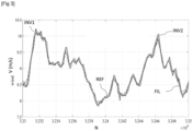
figure 3 illustre des courbes de la vitesse effective du vent dans le plan du rotor, parmi lesquelles une courbe de référence, et trois courbes obtenues par le procédé selon trois modes de réalisation l'invention pour un exemple d'application.Therepicture 3
La présente invention concerne un procédé de détermination en temps réel de la vitesse du vent dans le plan du rotor d'une éolienne, par exemple la vitesse de vent effective dans le plan du rotor d'une éolienne.The present invention relates to a method for determining in real time the wind speed in the rotor plane of a wind turbine, for example the effective wind speed in the rotor plane of a wind turbine.
La
un mât 4 permettant de placer un rotor (non représenté) à une hauteur suffisante pour permettre son mouvement (nécessaire pour les éoliennes à axe horizontal) ou de placer ce rotor à une hauteur lui permettant d'être entraîné par un vent plus fort et régulier qu'au niveau dusol 6. Le mât 4 peut abriter généralement une partie des composants électriques et électroniques (modulateur, commande, multiplicateur, générateur, ...) ;une nacelle 3 montée au sommet du mât 4, abritant des composants mécaniques, pneumatiques, certains composants électriques et électroniques (non représentés), nécessaires au fonctionnement de la machine de conversion.La nacelle 3 peut tourner pour orienter le rotor dans la bonne direction ;- le rotor, fixé à la nacelle, comprenant plusieurs pales 7 (en général trois) et le nez de l'éolienne. Le rotor est entraîné par l'énergie du vent, il est relié par un arbre mécanique directement ou indirectement (via un système de boîte de vitesse et d'arbre mécanique) à une machine électrique (générateur électrique...) ou toute autre machine de conversion (par exemple machine hydraulique ou pneumatique) qui convertit l'énergie recueillie en énergie électrique ou toute autre énergie (par exemple hydraulique ou pneumatique). Le rotor est potentiellement doté de systèmes de contrôle tels que des pales à angle variable ou des freins aérodynamiques ;
- éventuellement une transmission (non représentée), composée de deux axes (arbre mécanique du rotor et arbre mécanique de la machine de conversion) reliés, formant ainsi une chaîne cinématique entre l'arbre mécanique du rotor et l'arbre mécanique de la machine de conversion.
- a
mast 4 making it possible to place a rotor (not shown) at a sufficient height to allow its movement (necessary for horizontal axis wind turbines) or to place this rotor at a height allowing it to be driven by a stronger and more regular wind only atground level 6.Mast 4 can generally house some of the electrical and electronic components (modulator, control, multiplier, generator, etc.); - a
nacelle 3 mounted at the top of themast 4, housing mechanical and pneumatic components, certain electrical and electronic components (not shown), necessary for the operation of the conversion machine. Thenacelle 3 can turn to orient the rotor in the right direction; - the rotor, fixed to the nacelle, comprising several blades 7 (generally three) and the nose of the wind turbine. The rotor is driven by the energy of the wind, it is connected by a mechanical shaft directly or indirectly (via a gearbox and mechanical shaft system) to an electric machine (electric generator...) or any other machine converter (eg hydraulic or pneumatic machine) which converts the collected energy into electrical energy or any other energy (eg hydraulic or pneumatic). The rotor is potentially equipped with control systems such as variable angle blades or aerodynamic brakes;
- possibly a transmission (not shown), consisting of two axes (mechanical shaft of the rotor and mechanical shaft of the conversion machine) connected, thus forming a kinematic chain between the mechanical shaft of the rotor and the mechanical shaft of the conversion machine .
Sur cette figure, sont représentés également les axes x, y et z. Le point de référence de ce repère est le centre du rotor. La direction x est la direction longitudinale, correspondant à la direction de l'axe du rotor, en amont de l'éolienne. La direction y, perpendiculaire à la direction x, est la direction latérale située dans un plan horizontal (les directions x, y forment un plan horizontal). La direction z est la direction verticale (correspondant sensiblement à la direction du mât 4) dirigée vers le haut, l'axe z est perpendiculaire aux axes x et y. Le plan du rotor est indiqué par le rectangle en traits pointillés PR, il est défini par les directions y, z pour une valeur de x nulle.This figure also shows the x, y and z axes. The reference point of this mark is the center of the rotor. The x direction is the longitudinal direction, corresponding to the direction of the rotor axis, upstream of the wind turbine. The y direction, perpendicular to the x direction, is the lateral direction located in a horizontal plane (the x, y directions form a horizontal plane). The z direction is the vertical direction (corresponding substantially to the direction of the mast 4) directed upwards, the z axis is perpendicular to the x and y axes. The rotor plane is indicated by the rectangle in dotted lines PR, it is defined by the directions y, z for a zero value of x.
Selon l'invention, le procédé de détermination de la vitesse du vent comporte les étapes suivantes :
- 1/ Construction d'un modèle d'éolienne
- 2/ Mesures
- 3/ Détermination de la vitesse du vent
- 1/ Construction of a wind turbine model
- 2/ Measurements
- 3/ Determination of the wind speed
Les étapes 2 et 3 sont réalisées en temps réel, alors que l'étape 1 de construction du modèle d'éolienne est réalisée préalablement, une seule fois. Ces étapes peuvent être mises en oeuvre automatiquement par des moyens informatiques, notamment par un contrôleur d'une éolienne, qui comportent à minima une mémoire et des moyens de calcul. Ces étapes sont détaillées dans la suite de la description.
La première étape de construction du modèle d'éolienne est mise en oeuvre au moyen de sous-étapes, de telle sorte que le procédé de détermination de la vitesse du vent comporte les étapes suivantes :
- 1/ Construction d'un modèle d'éolienne
- a/ Mesures simultanées
- b/ Classement par groupement
- c/ Régressions
- d/ Construction du modèle d'éolienne
- 2/ Mesures
- 3/ Détermination de la vitesse du vent
- 1/ Construction of a wind turbine model
- a/ Simultaneous measurements
- b/ Classification by group
- c/ Regressions
- d/ Construction of the wind turbine model
- 2/ Measurements
- 3/ Determination of the wind speed
La
Selon un mode de réalisation, la présente invention peut être mise en oeuvre pour une détermination de la vitesse actuelle du vent (on peut parler alors de filtrage).According to one embodiment, the present invention can be implemented for a determination of the current wind speed (one can then speak of filtering).
En variante, la présente invention peut être mise en oeuvre pour une prédiction de la vitesse du vent pour au moins un pas de temps futur (on peut parler alors de prédiction).As a variant, the present invention can be implemented for a prediction of the wind speed for at least one future time step (one can then speak of a prediction).
Lors de cette étape, on construit un modèle d'éolienne. Un modèle d'éolienne est un modèle qui relie la vitesse de rotation du rotor, l'angle d'inclinaison des pales de l'éolienne, la puissance générée par une machine de conversion de l'éolienne à la vitesse de vent dans le plan du rotor de l'éolienne. Selon l'invention, on met en oeuvre cette étape une unique fois, préalablement lors d'une campagne d'entraînement du modèle. Puis, en temps réel, en utilisation de l'éolienne, on conserve le modèle d'éolienne construit, et on met en oeuvre uniquement les étapes 2 et 3. Ce modèle d'éolienne peut être vu comme une cartographie (de l'anglais « map ») de l'éolienne.During this stage, a model of a wind turbine is built. A wind turbine model is a model that relates the rotational speed of the rotor, the angle of inclination of the wind turbine blades, the power generated by a wind turbine conversion machine with the wind speed in the plane of the wind turbine rotor. According to the invention, this step is implemented only once, beforehand during a model training campaign. Then, in real time, in use of the wind turbine, the constructed wind turbine model is kept, and only steps 2 and 3 are implemented. This wind turbine model can be seen as a cartography (from the English "map") of the wind turbine.
Pour cette étape, on met en oeuvre les sous-étapes suivantes :For this step, the following sub-steps are implemented:
Lors de cette sous-étape, on mesure simultanément la vitesse du vent dans le plan du rotor ainsi que la vitesse de rotation du rotor, l'angle d'inclinaison des pales de l'éolienne, la puissance générée par une machine de conversion de l'éolienne (en d'autres termes la puissance générée par l'éolienne). Toutes ces mesures permettent d'entraîner le modèle d'éolienne. On peut noter qu'on mesure la vitesse du vent uniquement dans cette étape de construction, en effet, cette mesure n'est pas mise en oeuvre en temps réel. Ainsi, en temps réel, le procédé selon l'invention ne nécessite pas d'instrumentation spécifique. Cette mesure de la vitesse du vent permet de construire un modèle d'éolienne représentatif, c'est-à-dire qui permet de remplacer le capteur de vitesse du vent.During this sub-step, we simultaneously measure the wind speed in the plane of the rotor as well as the rotational speed of the rotor, the angle of inclination of the blades of the wind turbine, the power generated by a conversion machine of the wind turbine (in other words the power generated by the wind turbine). All these measurements are used to train the wind turbine model. It may be noted that the wind speed is measured only in this construction stage, indeed, this measurement is not implemented in real time. Thus, in real time, the method according to the invention does not require specific instrumentation. This measurement of the wind speed makes it possible to construct a representative wind turbine model, that is to say which makes it possible to replace the wind speed sensor.
Selon un mode de réalisation de l'invention, on peut mesurer la vitesse du vent dans le plan du rotor au moyen d'un capteur placé sur l'éolienne, par exemple un capteur LiDAR. Pour ce mode de réalisation de l'invention, on peut mettre en oeuvre une méthode de reconstruction de la vitesse de vent, telle que décrite notamment dans les demandes de brevet
Alternativement, on peut mesurer la vitesse du vent dans le plan du rotor par tout autre moyen, par exemple au moyen d'un anémomètre ou tout capteur équivalent.Alternatively, the wind speed in the plane of the rotor can be measured by any other means, for example by means of an anemometer or any equivalent sensor.
Conformément à une mise en oeuvre de l'invention, on peut mesurer la vitesse de rotation du rotor, l'angle d'inclinaison des pales de l'éolienne, la puissance générée par une machine de conversion de l'éolienne obtenue à partir d'un système de contrôle et d'acquisition de données en temps réel (SCADA). Un système de contrôle et d'acquisition de données en temps réel (SCADA) (de l'anglais : « Supervisory Control And Data Acquisition ») est un système de télégestion à grande échelle permettant de traiter en temps réel un grand nombre de télémesures et de contrôler à distance des installations techniques. C'est une technologie industrielle dans le domaine de l'instrumentation, dont les implémentations peuvent être considérées comme des structures d'instrumentation incluant une couche de type intergiciel (de l'anglais « middleware »). De préférence, toutes les mesures peuvent être obtenues à partir du système SCADA, ce qui facilite la mise en oeuvre du procédé sans instrumentation particulière. En outre, le système SCADA peut permettre de prendre en compte au moins une autre mesure pour rendre la détermination de la vitesse du vent dans le plan du rotor plus précise. Il peut s'agir notamment de températures, de données électriques, de vibrations, etc. Les températures peuvent informer sur les pertes mécaniques effectives, et permettent ainsi d'affiner la modélisation de l'éolienne. L'accélérométrie, associée à une compréhension modale et vibratoire suffisamment fine et fidèle de la structure, peut permettre de remonter à une estimation de l'état du vent et des turbulences impactant l'éolienne.According to an implementation of the invention, it is possible to measure the speed of rotation of the rotor, the angle of inclination of the blades of the wind turbine, the power generated by a conversion machine of the wind turbine obtained from a real-time control and data acquisition (SCADA) system. A real-time supervisory control and data acquisition (SCADA) system is a large-scale remote management system that can process a large number of remote measurements and to remotely control technical installations. It is an industrial technology in the field of instrumentation, the implementations of which can be considered as instrumentation structures including a middleware type layer. Preferably, all the measurements can be obtained from the SCADA system, which facilitates the implementation of the method without particular instrumentation. In addition, the SCADA system can make it possible to take into account at least one other measurement to make the determination of the wind speed in the plane of the rotor more precise. This may include temperatures, electrical data, vibrations, etc. The temperatures can provide information on the effective mechanical losses, and thus make it possible to refine the modeling of the wind turbine. Accelerometry, associated with a sufficiently fine and accurate modal and vibrational understanding of the structure, can make it possible to trace back to an estimate of the state of the wind and turbulence impacting the wind turbine.
Alternativement, au moins une des mesures peut être obtenue par un capteur dédié. Pour cette réalisation :
- pour la mesure de la vitesse de rotation du rotor, on peut utiliser un capteur de rotation angulaire du rotor, et/ou
- pour la mesure de l'angle d'inclinaison des pales, on peut utiliser un capteur angulaire des pales, et/ou
- pour la mesure de la puissance générée par la machine de conversion, on peut utiliser un capteur de tension connue et contrôlée, et un capteur d'intensité pour la mesure du courant débité par la génératrice.
- for measuring the speed of rotation of the rotor, a sensor of the angular rotation of the rotor can be used, and/or
- for measuring the angle of inclination of the blades, a blade angle sensor can be used, and/or
- for measuring the power generated by the conversion machine, a known and controlled voltage sensor can be used, and an intensity sensor for measuring the current delivered by the generator.
Lors de cette étape, on peut également mémoriser les mesures, notamment pour la mise en oeuvre dans laquelle on utilise les mesures antérieures (décrite ci-après dans la sous-étape c).During this step, it is also possible to store the measurements, in particular for the implementation in which the previous measurements are used (described below in sub-step c).
Lors de cette sous-étape, on classe toutes les mesures de la sous-étape 1/a (vitesse du vent dans le plan du rotor et vitesse de rotation du rotor, puissance générée et angle d'inclinaison des pales) en au moins deux classes, appelés aussi groupements (en anglais « clusters ») de conditions de fonctionnement de l'éolienne. On peut parler de sous-étape de « classification » ou de « partitionnement des données ». En d'autres termes, on classe l'ensemble des mesures, en plusieurs groupements, chaque groupement réunissant des mesures du capteur de vitesse de vent, et les mesures issues de l'éolienne (vitesse du rotor, angle d'inclinaison des pales, puissance générée) qui correspondent à des conditions de fonctionnement de l'éolienne similaires.During this sub-step, all the measurements of
Selon un mode de réalisation de l'invention, on peut classer automatiquement les mesures des deux types au moyen d'un algorithme du k-means, de préférence un algortihme de k-means ++. Un tel algorithme est décrit notamment dans le document : «
Alternativement, tout autre algorithme automatique de classement peut être utilisé, par exemple un algorithme de "clustering" hiérarchique, ou un algorithme DBSCAN (de l'anglais : « density-based spatial clustering of applications with noise» pouvant être traduit par classement spatial basé sur la densité d'applications bruitées), etc.Alternatively, any other automatic classification algorithm can be used, for example a hierarchical "clustering" algorithm, or a DBSCAN algorithm (from the English: "density-based spatial clustering of applications with noise" which can be translated by spatial classification based on the density of noisy applications), etc.
Conformément à une mise en oeuvre de l'invention, le nombre de groupements peut être compris entre 3 et 10, de préférence entre 4 et 7, et peut valoir par exemple 5. Ces gammes de valeur permettent de bien différencier les conditions de fonctionnement de l'éolienne, tout en limitant la complexité de la construction du modèle d'éolienne, qui pourrait résulter d'un grand nombre de groupements.In accordance with one implementation of the invention, the number of groups can be between 3 and 10, preferably between 4 and 7, and can for example be equal to 5. These value ranges make it possible to clearly differentiate the operating conditions of the wind turbine, while limiting the complexity of the construction of the wind turbine model, which could result from a large number of groupings.
Lors de cette sous- étape, pour chaque groupement déterminé à la sous-étape précédente, on détermine une régression entre les mesures simultanées de la sous-étape a (vitesse du vent dans le plan du rotor, vitesse de rotation du rotor, angle d'inclinaison des pales, et puissance générée) par une méthode de décomposition en fonctions de base et par une méthode permettant d'établir une relation entre ces fonctions de base et la vitesse du vent dans le plan du rotor. Avantageusement, on peut mettre en oeuvre une méthode de régression par processus gaussien et une méthode de régression par les moindres carrés. Ces méthodes de régression permettent de relier les mesures liées à l'éolienne (vitesse de rotation du rotor, angle d'inclinaison des pales, puissance générées) à la vitesse du vent. La méthode de régression par processus gaussien est une régression non paramétrique qui permet de sélectionner des fonctions de base pour la décomposition. Une telle régression de processus gaussien est flexible, et sans problème de sur-apprentissage (variables trop nombreuses et modèle trop complexe). La méthode de régression par les moindres carrées est une régression paramétrique simple à mettre en oeuvre, qui permet d'établir une relation entre les fonctions de base et la vitesse du vent dans le plan du rotor. Alternativement, on peut mettre en oeuvre tout autre méthode de régression permettant d'établir une relation entre ces fonctions de base et la vitesse du vent dans le plan du rotor.During this sub-step, for each grouping determined in the previous sub-step, a regression is determined between the simultaneous measurements of sub-step a (wind speed in the plane of the rotor, rotational speed of the rotor, angle d inclination of the blades, and power generated) by a method of decomposition into basic functions and by a method making it possible to establish a relationship between these basic functions and the speed of the wind in the plane of the rotor. Advantageously, a Gaussian process regression method and a least squares regression method can be implemented. These regression methods make it possible to link measurements related to the wind turbine (rotor rotation speed, blade inclination angle, power generated) to wind speed. The Gaussian process regression method is a nonparametric regression that allows selection of basis functions for the decomposition. Such a Gaussian process regression is flexible, and without over-fitting problems (too many variables and too complex model). The least squares regression method is a simple parametric regression to implement, which makes it possible to establish a relationship between the basis functions and the wind speed in the plane of the rotor. Alternatively, it is possible to implement any other regression method making it possible to establish a relationship between these basic functions and the speed of the wind in the plane of the rotor.
De préférence, la régression peut prendre en compte les mesures antérieures, de préférence, la régression peut prendre en compte un nombre de pas de temps antérieurs afin de favoriser la précision de la détermination de la vitesse du vent. Pour cela, on peut relier, un nombre r de dernières mesures de la vitesse de rotation du rotor, de l'angle d'inclinaison des pales, et la puissance générée par la machine de conversion à la vitesse du vent dans le plan du rotor. Par exemple, si on considère qu'on prend un historique de r = 30 pas de temps antérieurs, on aura 90 mesures (entrées) reliées à la vitesse du vent dans le plan du rotor au pas de temps courant, ou pour au moins un pas de temps futur.Preferably, the regression can take into account the previous measurements, preferably, the regression can take into account a number of previous time steps in order to favor the precision of the determination of the wind speed. For this, we can relate, a number r of last measurements of the rotational speed of the rotor, the angle of inclination of the blades, and the power generated by the conversion machine to the wind speed in the plane of the rotor . For example, if we consider that we take a history of r = 30 previous time steps, we will have 90 measurements (inputs) related to the wind speed in the plane of the rotor at the current time step, or for at least one no future tense.
On décrit ci-dessous un exemple de réalisation non limitatif de cette sous-étape :
- On note ωt la vitesse angulaire du rotor au temps t, pt la puissance générée au temps t, βt l'angle d'inclinaison des pales au temps t, vt la vitesse du vent au temps t. Le but est de déterminer y, étant donné xt-h, en posant yt=vt et

- Avec r et h des entiers choisis de telle sorte que r > h ≥ 0, et on note

- We note ω t the angular speed of the rotor at time t, p t the power generated at time t, β t the angle of inclination of the blades at time t, v t the wind speed at time t. The goal is to determine y, given x th , by setting y t =v t and
- With r and h integers chosen such that r > h ≥ 0, and we denote
Ainsi, on se sert des mesures collectées entre t-r et t-h pour estimer la vitesse du vent au temps t. Les mêmes notations sont utilisées pour l'angle d'inclinaison des pales et pour la puissance générée. Si on utilise un filtrage (une détermination de la vitesse du vent actuel), on définit h = 0, alors que si on met en oeuvre une prédiction de la vitesse du vent, on définit h>0, par exemple h = 1 ou h = 2.Thus, we use the measurements collected between t-r and t-h to estimate the wind speed at time t. The same notations are used for the angle of inclination of the blades and for the power generated. If we use filtering (a determination of the speed of the current wind), we define h = 0, whereas if we implement a prediction of the wind speed, we define h>0, for example h = 1 or h = 2.
Dans chaque groupement, on applique une méthode de régression par processus gaussien GPR (de l'anglais « Gaussian Process Regression »), pour cela, on définit un noyau (de l'anglais « kernel ») k qui codifie les informations a priori sur la fonction latente qui relie les entrées à la sortie : 
Avec 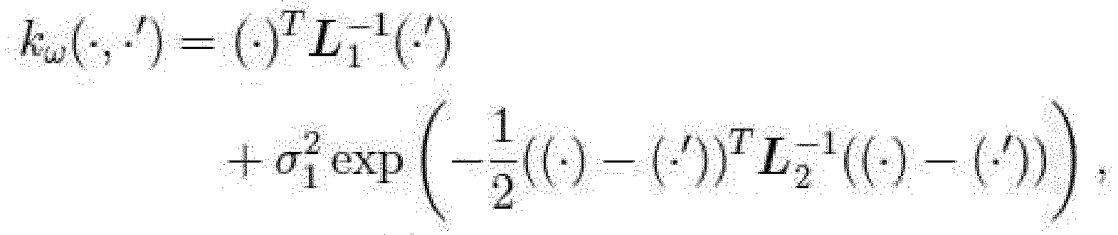


![]()
- 1) les contributions linéaires (c'est-à-dire celles de la forme (·) TLi (·')) tiennent compte du fait qu'on s'attend à ce que la vitesse du vent soit plus élevée lorsque l'éolienne produit plus d'énergie et lorsque que la vitesse du rotor est plus rapide ;
- 2) les contributions non linéaires tiennent compte de la dynamique plus complexe de la turbine ;
- 3) les matrices Li sont telles que présentées dans les équations ci-dessus afin d'obtenir des poids plus faibles pour les composants d'entrée contenant des informations plus détaillées dans le passé tout en conservant un petit nombre d'hyper-paramètres à sélectionner.
- 1) the linear contributions (i.e. those of the form ( ) T L i ( ')) take into account that the wind speed is expected to be higher when l turbine produces more energy and when the rotor speed is faster;
- 2) the nonlinear contributions take into account the more complex dynamics of the turbine;
- 3) the Li matrices are as presented in the equations above in order to obtain lower weights for input components containing more detailed information in the past while keeping a small number of hyper-parameters to select from .
On utilise la fonction moyenne m = 0, de telle sorte qu'on obtient toutes les caractéristiques de la fonction latente à capturer par le noyau.We use the average function m = 0, so that we obtain all the characteristics of the latent function to be captured by the kernel.
Une fois que les hyper-paramètres du noyau de chaque groupement ont été déterminés, l'étape suivante est de réaliser la régression. Pour cela, on peut sélectionner N paires de mesures (xi-h, yi) de chaque groupement en tant que données d'entraînement. La sélection de N paires de mesures permet d'accélérer la construction du modèle d'éolienne par rapport à un mode de réalisation pour lequel on considère l'ensemble des mesures. On note que, normalement, pour chaque point considéré en temps réel x ∗, on pourrait trouver une estimation définie par : ŷ∗ = k(x ∗, X)Kyy avec X est la matrice constuite à partir des N données d'entraînement et Ky = k(X, X) + σ 2 ∗ I avec k(X,X) est une matrice de telle sorte que sa valeur à la position (i, j) est k(xi, xj), où xi et xj sont les lignes i et j de X, σ2 est la variance du bruit et I est la matrice identité.Once the kernel hyperparameters of each cluster have been determined, the next step is to perform the regression. For this, it is possible to select N pairs of measurements (x ih , y i ) from each grouping as training data. The selection of N pairs of measurements makes it possible to accelerate the construction of the wind turbine model with respect to an embodiment for which all the measurements are considered. We note that, normally, for each point considered in real time x ∗ , we could find an estimate defined by: ŷ ∗ = k ( x ∗ , X ) K y y with X is the matrix built from the N data of training and K y = k(X, X) + σ 2 ∗ I with k(X,X) is a matrix such that its value at position (i, j) is k(x i , x j ), where x i and x j are the i and j rows of X, σ 2 is the noise variance and I is the identity matrix.
Cependant, dans une application réelle, l'algorithme estime ŷ ∗ en temps réel, et le temps de calcul de k (x ∗, X) est dimensionné par la taille N des données d'entraînement. En effet, plus N est grand, plus long est le temps de calcul. De plus, un grand nombre de données d'entraînement permet de former un modèle d'éolienne précis qui relie les données mesurées à la vitesse du vent.However, in a real application, the algorithm estimates ŷ ∗ in real time, and the computation time of k ( x ∗ , X ) is scaled by the size N of the training data. Indeed, the larger N, the longer the computation time. In addition, a large amount of training data helps to train an accurate wind turbine model that relates the measured data to the wind speed.
Pour résoudre ce problème, on peut mettre en oeuvre la méthode proposée dans le document : « ![]()
![]()
Avec 
-
X est obtenu en supprimant un nombre de lignes de X,Ky est obtenue par suppression des lignes correspondantes de Ky, µ>0 est un coefficient de régularisation, M est le nombre de lignes de la matriceX . On peut noter queα dépend seulement des données d'entraînement, - par conséquent, on peut stocker cette valeur, et ensuite calculer k(x ∗,
X ) pour chaque nouveau point en temps réel. La suppression des lignes de X et Ky permet de limiter le nombre de calculs, tout en conservant une bonne représentativité, notamment grâce aux groupements déterminés.
-
X is obtained by removing a number of rows from X,Ky is obtained by deleting the corresponding rows of Ky, µ>0 is a regularization coefficient, M is the number of rows of the matrixX . It can be noted thatα only depends on training data, - therefore, one can store this value, and then compute k ( x ∗ ,
X ) for each new point in real time. The suppression of the lines of X and Ky makes it possible to limit the number of calculations, while preserving a good representativeness, in particular thanks to determined groupings.
Ainsi, la régression mise en oeuvre permet de déterminer les paramètres
Lors de cette sous-étape, on construit le modèle d'éolienne au moyen des régressions déterminées pour chaque groupement.During this sub-step, the wind turbine model is constructed using the regressions determined for each grouping.
Ainsi, l'ensemble des régressions pour chaque groupement permet de déterminer un modèle d'éolienne.Thus, the set of regressions for each grouping makes it possible to determine a wind turbine model.
Lors de cette étape, on mesure, en temps réel :
- La vitesse de rotation du rotor,
- L'angle d'inclinaison des pales, et
- La puissance générée par la machine de conversion (en d'autres termes la puissance générée par l'éolienne).
- The rotational speed of the rotor,
- The pitch angle of the blades, and
- The power generated by the conversion machine (in other words the power generated by the wind turbine).
Ces mesures peuvent préférablement être mises en oeuvre de la même manière que les mesures simultanées de la sous-étape 1/a.These measurements can preferably be implemented in the same way as the simultaneous measurements of
Lors de cette étape, on peut également mémoriser les mesures, notamment pour la mise en oeuvre dans laquelle on utilise les mesures antérieures.During this step, it is also possible to store the measurements, in particular for the implementation in which the previous measurements are used.
Selon un mode de réalisation de l'invention, au moins une des mesures peut être obtenue à partir d'un système de contrôle et d'acquisition de données en temps réel (SCADA). Un système de contrôle et d'acquisition de données en temps réel (SCADA) (de l'anglais : « Supervisory Control And Data Acquisition ») est un système de télégestion à grande échelle permettant de traiter en temps réel un grand nombre de télémesures et de contrôler à distance des installations techniques. C'est une technologie industrielle dans le domaine de l'instrumentation, dont les implémentations peuvent être considérées comme des structures d'instrumentation incluant une couche de type intergiciel (de l'anglais « middleware »). De préférence, toutes les mesures peuvent être obtenues à partir du système SCADA, ce qui facilite la mise en oeuvre du procédé sans instrumentation particulière. En outre, le système SCADA peut permettre de prendre en compte au moins une autre mesure pour rendre la détermination de la vitesse du vent dans le plan du rotor plus précise. Il peut s'agir notamment de températures, de données électriques, de vibrations, etc. Les températures peuvent informer sur les pertes mécaniques effectives, et permettent ainsi d'affiner la modélisation de l'éolienne. L'accélérométrie, associée à une compréhension modale et vibratoire suffisamment fine et fidèle de la structure, peut permettre de remonter à une estimation de l'état du vent et des turbulences impactant l'éolienne.According to an embodiment of the invention, at least one of the measurements can be obtained from a real-time control and data acquisition (SCADA) system. A real-time supervisory control and data acquisition (SCADA) system is a large-scale remote management system that can process a large number of remote measurements and to remotely control technical installations. It is an industrial technology in the field of instrumentation, the implementations of which can be considered as instrumentation structures including a middleware type layer. Preferably, all the measurements can be obtained from the SCADA system, which facilitates the implementation of the method without particular instrumentation. In addition, the SCADA system can make it possible to take into account at least one other measurement to make the determination of the wind speed in the plane of the rotor more precise. This may include temperatures, electrical data, vibrations, etc. The temperatures can provide information on the effective mechanical losses, and thus make it possible to refine the modeling of the wind turbine. Accelerometry, associated with a sufficiently fine and accurate modal and vibrational understanding of the structure, can make it possible to trace back to an estimate of the state of the wind and turbulence impacting the wind turbine.
Alternativement, au moins une des mesures peut être obtenue par un capteur dédié. Pour cette réalisation :
- pour la mesure de la vitesse de rotation du rotor, on peut utiliser un capteur de rotation angulaire du rotor, et/ou
- pour la mesure de l'angle d'inclinaison des pales, on peut utiliser un capteur angulaire des pales, et/ou
- pour la mesure de la puissance générée par la machine de conversion, on peut utiliser un capteur de tension connue et contrôlée, et un capteur d'intensité pour la mesure du courant débité par la génératrice.
- for measuring the speed of rotation of the rotor, a sensor of the angular rotation of the rotor can be used, and/or
- for measuring the angle of inclination of the blades, a blade angle sensor can be used, and/or
- for measuring the power generated by the conversion machine, a known and controlled voltage sensor can be used, and an intensity sensor for measuring the current delivered by the generator.
Lors de cette étape, on détermine, en temps réel, la vitesse du vent dans le plan du rotor, au moyen des mesures effectuées à l'étape 2 et du modèle construit à l'étape 1. Ainsi, on obtient une détermination de la vitesse de vent de manière précise.During this step, we determine, in real time, the wind speed in the plane of the rotor, using the measurements made in step 2 and the model built in
Selon un mode de réalisation de l'invention, on peut déterminer la vitesse du vent actuelle.According to one embodiment of the invention, the current wind speed can be determined.
En variante, on peut prédire la vitesse du vent pour au moins un pas de temps futur. Par exemple, on peut prédire la vitesse du vent pour un pas de temps futur ou pour deux pas de temps futurs.Alternatively, the wind speed can be predicted for at least one future time step. For example, one can predict the wind speed for a future time step or for two future time steps.
Avantageusement, on peut associer les mesures de l'étape 2 à au moins un groupement déterminé à la sous-étape 1/b, et on applique la régression qui a été déterminée pour ce groupement aux mesures. Ainsi, on applique une régression qui correspond aux mêmes conditions de fonctionnement de l'éolienne.Advantageously, the measurements of step 2 can be associated with at least one group determined in
Conformément à une mise en oeuvre de l'invention, on peut déterminer, en temps réel, la vitesse du vent dans le plan du rotor de l'éolienne en déterminant la distance euclidienne entre les mesures en temps réel de l'étape 2 et les centres des groupements du modèle construits lors de la sous-étape 1/b. Puis, on peut appliquer le modèle d'éolienne au moyen d'une combinaison pondérée des régressions de chaque groupement. La pondération mise en oeuvre dans cette combinaison pondérée peut être dépendante de la distance euclidienne déterminée. Ainsi, on associe les mesures de l'étape 2 à au moins un groupement, qui correspond aux mêmes conditions de fonctionnement de l'éolienne, la détermination de la distance euclidienne permettant de déterminer le ou les groupements les plus proches, donc ceux qui ont les mêmes conditions de fonctionnement de l'éolienne.In accordance with an implementation of the invention, it is possible to determine, in real time, the wind speed in the plane of the rotor of the wind turbine by determining the Euclidean distance between the real-time measurements of step 2 and the centers of the clusters of the model constructed during
On peut réaliser cette mise en oeuvre de l'invention au moyen des étapes suivantes :
On note C le nombre de groupements du modèle d'éolienne. On note, ŷ 1,∗ ..., ŷC,∗ les valeurs déterminées de la vitesse du vent pour chaque groupement (de 1 à C). De plus, on note ci le centre du groupement i, ce centre est défini à partir des mesures associées lors de la sous étape 1/b.This implementation of the invention can be carried out by means of the following steps:
We note C the number of groups of the wind turbine model. We note, ŷ 1 ,∗ ..., ŷ C , ∗ the determined values of the wind speed for each grouping (from 1 to C). Moreover, we denote c i the center of group i, this center is defined from the associated measurements during
On peut combiner ces valeurs déterminées au moyen d'une combinaison pondérée définie par : 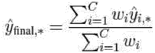
On peut calculer la pondération en tant que fonction de la distance euclidienne entre les mesures considérées x ∗ (pour lesquelles on détermine la vitesse du vent) et le groupement considéré. Ainsi, la pondération peut s'écrire : 
N est un paramètre libre à prédéterminé, avec n>0, plus la valeur de n est grand, moins on considère les contributions des groupements éloignés des mesures considérées.N is a free to predetermined parameter, with n>0, the greater the value of n, the less the contributions of the groups distant from the measurements considered are considered.
Le cas extrême correspond au cas pour lequel wi = 1 pour le groupement dont le centre est le plus proche des mesures considérées x ∗, et 0 pour les autres, en d'autres termes : 
La présente invention concerne également un procédé de contrôle d'au moins une éolienne. Pour ce procédé, on peut mettre en oeuvre les étapes suivantes :
- on détermine la vitesse du vent dans le plan du rotor de l'éolienne au moyen du procédé de détermination de la vitesse du vent selon l'une quelconque des variantes ou des combinaisons de variantes décrites ci-dessus ; et
- on contrôle l'éolienne en fonction de la vitesse du vent dans le plan du rotor de l'éolienne.
- the wind speed in the plane of the rotor of the wind turbine is determined by means of the method for determining the wind speed according to any one of the variants or combinations of variants described above; And
- the wind turbine is controlled according to the wind speed in the plane of the wind turbine rotor.
La prédiction précise et en temps réel de la vitesse du vent dans le plan du rotor de l'éolienne permet un contrôle adapté de l'éolienne, en termes de minimisation des effets sur la structure de l'éolienne et de maximisation de la puissance récupérée. En effet, au moyen de ce contrôle, on peut adapter les équipements de l'éolienne pour que l'éolienne soit dans la configuration optimale pour ce vent.Accurate and real-time prediction of the wind speed in the plane of the wind turbine rotor allows suitable control of the wind turbine, in terms of minimizing the effects on the structure of the wind turbine and maximizing the power harvested . Indeed, by means of this control, it is possible to adapt the equipment of the wind turbine so that the wind turbine is in the optimum configuration for this wind.
Conformément à une mise en oeuvre de l'invention, on peut commander l'angle d'inclinaison des pales et/ou le couple électrique de récupération du générateur de l'éolienne et/ou l'orientation de la nacelle en fonction de la vitesse du vent et de la direction du vent. De préférence, on peut commander l'angle d'inclinaison individuel des pales. D'autres types de dispositif de régulation peuvent être utilisés. Le contrôle d'inclinaison des pales permet d'optimiser la récupération d'énergie en fonction du vent incident sur les pales et de minimiser la fatigue de la structure.According to an implementation of the invention, it is possible to control the angle of inclination of the blades and/or the electrical recovery torque of the generator of the wind turbine and/or the orientation of the nacelle as a function of the speed wind and wind direction. Preferably, the individual pitch angle of the blades can be controlled. Other types of regulating device can be used. Blade pitch control optimizes energy recovery based on the incident wind on the blades and minimizes structural fatigue.
Selon un mode de réalisation de l'invention, l'angle d'inclinaison des pales et/ou le couple électrique de récupération peuvent être déterminés au moyen de cartographies de l'éolienne en fonction de la vitesse du vent au niveau du rotor. Par exemple, on peut appliquer le procédé de contrôle décrit dans la demande de brevet
La présente invention concerne également un procédé de surveillance et/ou diagnostic d'au moins une éolienne. Pour ce procédé, on peut mettre en oeuvre les étapes suivantes :
- on détermine la vitesse du vent dans le plan du rotor de l'éolienne au moyen du procédé de détermination de la vitesse du vent selon l'une quelconque des variantes ou des combinaisons de variantes décrites ci-dessus ; et
- on surveille et/ou on diagnostique le fonctionnement de l'éolienne en fonction de la vitesse du vent dans le plan du rotor.
- the wind speed in the plane of the rotor of the wind turbine is determined by means of the method for determining the wind speed according to any one of the variants or combinations of variants described above; And
- the operation of the wind turbine is monitored and/or diagnosed as a function of the wind speed in the plane of the rotor.
La surveillance et/ou le diagnostic peut par exemple correspondre à la sollicitation mécanique subie par la structure de l'éolienne en fonction de la vitesse du vent dans le plan du rotor de l'éolienne.The monitoring and/or the diagnosis can for example correspond to the mechanical stress undergone by the structure of the wind turbine as a function of the speed of the wind in the plane of the rotor of the wind turbine.
De plus, l'invention concerne un produit programme d'ordinateur, qui comprend des instructions de code agencés pour mettre en oeuvre les étapes d'un des procédés précédemment décrits (procédé de détermination de la direction du vent, procédé de contrôle, procédé de diagnostic). Le programme est exécuté sur une unité de contrôle et/ou de diagnostic de l'éolienne.Furthermore, the invention relates to a computer program product, which comprises code instructions arranged to implement the steps of one of the methods previously described (method for determining the direction of the wind, method of control, diagnostic process). The program is executed on a control and/or diagnostic unit of the wind turbine.
L'invention concerne également une éolienne, notamment une éolienne offshore (en mer) ou onshore (sur terre). L'éolienne est équipée de moyens de mesure de la rotation du rotor, de moyens de mesure de l'angle d'inclinaison des pales, et de moyens de mesure de la puissance générée par la machine de conversion. En outre, l'éolienne comporte des moyens de détermination de la vitesse du vent dans le plan du rotor aptes à mettre en oeuvre le procédé de détermination du vent selon l'une des variantes ou des combinaisons de variantes décrites ci-dessus. Selon un mode de réalisation, l'éolienne peut être conforme à l'éolienne illustrée en
Selon un mode de réalisation de l'invention, l'éolienne peut comporter un système de contrôle et d'acquisition de données en temps réel (SCADA) qui dispose d'au moins un moyen de mesure parmi les moyens de mesure de la rotation du rotor, les moyens de mesure de l'angle d'inclinaison des pales, et les moyens de mesure de la puissance générée par la machine de conversion. De préférence, le système SCADA peut disposer de toutes ces mesures. En outre, le système SCADA peut comporter des moyens de mesure supplémentaires (par exemple températures, mesures électriques, ...) qui peuvent permettre de rendre la détermination de la vitesse du vent dans le plan du rotor plus précise.According to one embodiment of the invention, the wind turbine may comprise a real-time control and data acquisition system (SCADA) which has at least one measuring means among the means for measuring the rotation of the rotor, the means for measuring the angle of inclination of the blades, and the means for measuring the power generated by the conversion machine. Preferably, the SCADA system can have all these measures. Furthermore, the SCADA system may include additional measurement means (for example temperatures, electrical measurements, etc.) which may make it possible to make the determination of the wind speed in the plane of the rotor more precise.
Alternativement, l'éolienne peut comporter au moins un capteur pour réaliser au moins une de ces mesures. Il peut donc s'agir :
- pour la mesure de la vitesse de rotation du rotor, d'un capteur de rotation angulaire du rotor, et/ou
- pour la mesure de l'angle d'inclinaison des pales, d'un capteur angulaire des pales, et/ou
- pour la mesure de la puissance générée par la machine de conversion, d'un capteur de tension connue et contrôlée, et un capteur d'intensité pour la mesure du courant débité par la génératrice.
- for measuring the rotational speed of the rotor, a sensor of the angular rotation of the rotor, and/or
- for measuring the angle of inclination of the blades, a blade angle sensor, and/or
- for measuring the power generated by the conversion machine, a known and controlled voltage sensor, and an intensity sensor for measuring the current delivered by the generator.
Pour le mode de réalisation du procédé de contrôle, l'éolienne peut comprendre des moyens de contrôle, par exemple le contrôle de l'angle d'inclinaison (pouvant être traduit par angle de tangage) d'au moins une pale de l'éolienne ou le contrôle du couple électrique, pour mettre en oeuvre le procédé de contrôle selon l'invention.For the embodiment of the control method, the wind turbine may comprise control means, for example the control of the angle of inclination (which can be translated as pitch angle) of at least one blade of the wind turbine or the control of the electric torque, to implement the control method according to the invention.
Comme il va de soi, l'invention ne se limite pas aux seules formes de réalisation des procédés décrits ci-dessus à titre d'exemple, elle embrasse au contraire toutes les variantes de réalisation.It goes without saying that the invention is not limited solely to the embodiments of the methods described above by way of example; on the contrary, it encompasses all variant embodiments.
Les caractéristiques et avantages du procédé selon l'invention apparaîtront plus clairement à la lecture de l'exemple d'application ci-après.The characteristics and advantages of the method according to the invention will appear more clearly on reading the application example below.
Pour cet exemple, on réalise la construction du modèle de l'éolienne au moyen de vitesse effective de vent dans le plan du rotor mesurée au moyen d'un capteur LiDAR, ces mesures LiDAR étant réalisées simultanément à des mesures SCADA de la vitesse de rotation du rotor, de l'angle d'inclinaison des pales et de la puissance générée.For this example, the construction of the model of the wind turbine is carried out by means of the effective wind speed in the plane of the rotor measured by means of a LiDAR sensor, these LiDAR measurements being carried out simultaneously with SCADA measurements of the rotation speed of the rotor, the angle of inclination of the blades and the power generated.
A partir de ces mesures, on forme un jeu de données d'entraînement appelé Strain, qu'on classifie en 5 groupements par l'algorithme du k-means++, et on en détermine leur centre. Puis, pour chaque groupement, on choisit aléatoirement N points pour construire la matrice X, et on choisit M points parmi les N points pour former la matrice
Pour cet exemple, la durée d'échantillonnage des mesures SCADA est d'une seconde, et la durée d'échantillonnage des données du capteur LiDAR est de 0,25 seconde. Pour cet exemple, on choisit, r=20, N=50000 et M=3000.For this example, the sample time for SCADA measurements is 1 second, and the sample time for LiDAR sensor data is 0.25 seconds. For this example, we choose, r=20, N=50000 and M=3000.
La
- la courbe de référence REF, obtenue à partir des mesures LiDAR,
- la courbe FIL de la vitesse du vent obtenue avec le procédé selon un premier mode de réalisation de l'invention pour lequel h=0, c'est-à-dire une détermination de la vitesse effective du vent actuel,
- la courbe INV1 de la vitesse du vent obtenue avec le procédé selon un deuxième mode de réalisation de l'invention pour lequel h=1, c'est-à-dire une prédiction de la vitesse effective du vent pour un pas de temps futur, et
- la courbe INV2 de la vitesse du vent obtenue avec procédé selon un troisième mode de réalisation de l'invention pour lequel h=2, c'est-à-dire une prédiction de la vitesse effective du vent pour deux pas de temps futurs.
- the reference curve REF, obtained from the LiDAR measurements,
- the curve FIL of the wind speed obtained with the method according to a first embodiment of the invention for which h=0, that is to say a determination of the effective speed of the current wind,
- the curve INV1 of the wind speed obtained with the method according to a second embodiment of the invention for which h=1, that is to say a prediction of the effective wind speed for a future time step, And
- the curve INV2 of the wind speed obtained with the method according to a third embodiment of the invention for which h=2, that is to say a prediction of the effective wind speed for two future time steps.
On remarque que les quatre courbes sont quasiment superposées, ce qui implique que les trois modes de réalisation de l'invention permettent une détermination précise de la vitesse du vent dans le plan du rotor, aussi bien pour le temps actuel que pour un ou deux pas de temps futurs.Note that the four curves are almost superimposed, which implies that the three embodiments of the invention allow precise determination of the wind speed in the plane of the rotor, both for the current weather and for one or two steps. of future times.
Claims (10)
- Method for determining a wind speed in the plane of a rotor (PR) of a wind turbine (1), characterized in that the following steps are implemented:a. constructing (CON) a wind turbine model (MOD) that links the rotational speed of said rotor of said wind turbine (1), the tilt angle of the blades of said wind turbine (1), and the power generated by a conversion machine of the wind turbine (1) to the wind speed in the plane of the rotor of said wind turbine, by way of the following steps:i. simultaneously measuring (LID, MES1) the wind speed in the plane of the rotor of said wind turbine along with the rotational speed of said rotor, the tilt angle of the blades and the power generated by said conversion machine of said wind turbine;ii. classifying (GRO) said simultaneous measurements of the wind speed in the plane of the rotor of said wind turbine along with the rotational speed of said rotor, the tilt angle of the blades and the power generated by said conversion machine of said wind turbine into at least two classes of operating conditions of the wind turbine;iii. for each class, determining a regression (REG) between the measurements of the wind speed in the plane of the rotor of said wind turbine along with the rotational speed of said rotor, the tilt angle of the blades and the power generated by said conversion machine of said wind turbine using a basic function decomposition method, and using a method for establishing a relationship between these basic functions and the wind speed in the plane of the rotor, preferably by way of a Gaussian process regression method and using a least squares regression method;iv. constructing said wind turbine model (MOD) by way of said regressions determined for each class;b. measuring (MES2), in real time (tpr), the rotational speed of said rotor, the tilt angle of the blades and the power generated by said conversion machine of said wind turbine; andc. determining, in real time (tpr), the wind speed v in the plane of said rotor of said wind turbine (1) by way of said real-time measurements (MES2) of the rotational speed of said rotor, of the tilt angle of the blades and of the power generated by said conversion machine of said wind turbine, and said wind turbine model.
- Method for determining wind speed according to Claim 1, wherein said measurements of the wind speed, of the rotational speed of said rotor, of the tilt angle of the blades and of the power generated by said conversion machine of said wind turbine are classified (GRO) into at least two classes of operating conditions of the wind turbine by way of a classification method, in particular by way of a k-means algorithm, preferably by way of a k-means++ algorithm.
- Method for determining wind speed according to either of the preceding claims, wherein the number of classes is between 3 and 10, preferably between 4 and 7.
- Method for determining wind speed according to one of the preceding claims, wherein the wind speed (LID) in the plane of the rotor is measured on the basis of measurements from a lidar sensor.
- Method for determining wind speed according to one of the preceding claims, wherein the wind speed (v) in the plane of said rotor of said wind turbine is determined in real time by determining the Euclidean distance between said real-time measurements of the rotational speed of said rotor, of the tilt angle of the blades and of the power generated by said conversion machine of said wind turbine and the centre of each class, and said model of the wind turbine (MOD) is applied by a weighted combination of said regressions of each class, the weighting being dependent on said Euclidean distance.
- Method for determining wind speed according to one of the preceding claims, wherein the wind speed (v) in the plane of said rotor of said wind turbine (1) is predicted for at least one future time increment, based on said wind turbine model (MOD) and said real-time measurements of the rotational speed of said rotor (MES2), of the tilt angle of the blades and of the power generated by said conversion machine of said wind turbine.
- Method for controlling a wind turbine (1), characterized in that the following steps are implemented:a. determining said wind speed in said rotor plane (PR) of the wind turbine (1) by way of the method according to one of the preceding claims;b. controlling said wind turbine (1) on the basis of said wind speed in said plane of the rotor of said wind turbine (1).
- Wind turbine (1), characterized in that it comprises means for measuring the rotational speed of said rotor, means for measuring the tilt angle of the blades of the wind turbine, means for measuring the power generated by the conversion machine of said wind turbine, and means for determining the wind speed in the plane of the rotor of the wind turbine, said means being able to implement the method according to one of Claims 1 to 7.
- Wind turbine according to Claim 8, comprising a real-time data acquisition and control system that comprises said means for measuring the rotational speed of said rotor, said means for measuring the tilt angle of the blades of the wind turbine, and said means for measuring the power generated by the conversion machine of said wind turbine.
- Computer program product, characterized in that it comprises code instructions that prompt the wind turbine according to Claim 8 or 9 to implement the steps of a method according to one of Claims 1-7 when the program is executed on a control and/or diagnostic unit of said wind turbine (1).
Applications Claiming Priority (1)
| Application Number | Priority Date | Filing Date | Title |
|---|---|---|---|
| FR2011395A FR3116123B1 (en) | 2020-11-06 | 2020-11-06 | Method for determining the wind speed in the plane of the rotor of a wind turbine |
Publications (3)
| Publication Number | Publication Date |
|---|---|
| EP3995834A1 EP3995834A1 (en) | 2022-05-11 |
| EP3995834B1 true EP3995834B1 (en) | 2023-08-23 |
| EP3995834C0 EP3995834C0 (en) | 2023-08-23 |
Family
ID=73793529
Family Applications (1)
| Application Number | Title | Priority Date | Filing Date |
|---|---|---|---|
| EP21204068.7A Active EP3995834B1 (en) | 2020-11-06 | 2021-10-21 | Method for determining the wind speed in the rotor plane of a wind turbine |
Country Status (6)
| Country | Link |
|---|---|
| US (1) | US11885305B2 (en) |
| EP (1) | EP3995834B1 (en) |
| CN (1) | CN114528648A (en) |
| CA (1) | CA3137278A1 (en) |
| ES (1) | ES2963166T3 (en) |
| FR (1) | FR3116123B1 (en) |
Family Cites Families (31)
| Publication number | Priority date | Publication date | Assignee | Title |
|---|---|---|---|---|
| US6320272B1 (en) * | 1997-03-26 | 2001-11-20 | Forskningscenter Riso | Wind turbine with a wind velocity measurement system |
| US7317260B2 (en) * | 2004-05-11 | 2008-01-08 | Clipper Windpower Technology, Inc. | Wind flow estimation and tracking using tower dynamics |
| JP2009501871A (en) * | 2005-07-18 | 2009-01-22 | クリッパー・ウィンドパワー・テクノロジー・インコーポレーテッド | Ventilation flow estimation and tracking using tower dynamics |
| US7363808B2 (en) * | 2005-12-05 | 2008-04-29 | General Electric Company | Method, system and computer program product for nacelle wind speed correction |
| US7823437B2 (en) * | 2007-06-18 | 2010-11-02 | General Electric Company | Anemometer calibration method and wind turbine |
| US8178986B2 (en) * | 2009-03-18 | 2012-05-15 | General Electric Company | Wind turbine operation system and method |
| US9189755B2 (en) * | 2009-06-05 | 2015-11-17 | Siemens Aktiengesellschaft | Available power estimator |
| FR2976630B1 (en) | 2011-06-17 | 2021-07-23 | Ifp Energies Now | PROCESS FOR OPTIMIZING THE POWER RECOVERED BY A WIND TURBINE BY REDUCING THE MECHANICAL IMPACT ON THE STRUCTURE. |
| FR2996266B1 (en) * | 2012-10-01 | 2014-09-12 | IFP Energies Nouvelles | METHOD FOR CONTROLLING A WINDMILL USING INCIDENT WIND SPEED ESTIMATION |
| DK2860395T3 (en) * | 2013-10-09 | 2017-11-13 | Siemens Ag | Automatic power estimation adjustment system |
| FR3013777B1 (en) | 2013-11-25 | 2015-11-13 | IFP Energies Nouvelles | METHOD OF MONITORING AND MONITORING A WIND TURBINE USING WIND SPEED ESTIMATION USING A LIDAR SENSOR |
| EP3221582B1 (en) * | 2014-11-21 | 2021-04-21 | Vestas Wind Systems A/S | A method for estimating a wind speed including calculating a pitch angle adjusted for blade torsion |
| CN107002637B (en) * | 2014-11-21 | 2019-03-22 | 维斯塔斯风力系统集团公司 | A method of for estimating wind speed in a stable manner |
| US10724499B2 (en) * | 2015-12-23 | 2020-07-28 | Vestas Wind Systems A/S | Controlling wind turbines according to reliability estimates |
| DE102016103254A1 (en) * | 2016-02-24 | 2017-08-24 | Wobben Properties Gmbh | Method for determining an equivalent wind speed |
| WO2017211367A1 (en) * | 2016-06-07 | 2017-12-14 | Vestas Wind Systems A/S | Adaptive control of a wind turbine by detecting a change in performance |
| US10539116B2 (en) * | 2016-07-13 | 2020-01-21 | General Electric Company | Systems and methods to correct induction for LIDAR-assisted wind turbine control |
| FR3068139B1 (en) | 2017-06-21 | 2019-12-20 | IFP Energies Nouvelles | PROCESS FOR ACQUISITION AND MODELING BY AN LIDAR SENSOR OF AN INCIDENT WIND FIELD |
| WO2019007579A1 (en) * | 2017-07-07 | 2019-01-10 | Siemens Gamesa Renewable Energy A/S | Determining a wind speed value |
| JP7009237B2 (en) * | 2018-01-31 | 2022-01-25 | 株式会社日立製作所 | Wind power generation equipment and wind power generation system |
| US10774811B2 (en) * | 2018-05-01 | 2020-09-15 | General Electric Company | Induction controlled wind turbine |
| US20200063710A1 (en) * | 2018-08-23 | 2020-02-27 | BluWave Inc. | System and methods for hyper short-term wind power prediction using real-time wind parameter measurements |
| EP3647587A1 (en) * | 2018-11-01 | 2020-05-06 | Wobben Properties GmbH | Method for controlling a wind turbine and corresponding wind turbine |
| CN109242218B (en) * | 2018-11-05 | 2022-07-12 | 南方电网科学研究院有限责任公司 | Method and device for predicting wind power in plateau mountain area based on SVM |
| FR3088971B1 (en) | 2018-11-26 | 2021-02-19 | Ifp Energies Now | method of acquisition and modeling by a LIDAR sensor of an incident wind field |
| FR3094093B1 (en) * | 2019-03-18 | 2021-03-05 | Ifp Energies Now | Method for predicting the wind speed in the plane of the rotor for a wind turbine equipped with a laser remote sensing sensor |
| EP3734063B1 (en) * | 2019-04-30 | 2023-03-01 | Wobben Properties GmbH | Method for controlling a wind turbine |
| FR3097644B1 (en) * | 2019-06-19 | 2021-06-11 | Ifp Energies Now | Method for determining the vertical profile of the wind speed upstream of a wind turbine equipped with a laser remote sensing sensor |
| CN110761947B (en) * | 2019-11-15 | 2020-09-11 | 华北电力大学 | Yaw calibration method and system for wind turbine generator |
| FR3107094B1 (en) * | 2020-02-10 | 2022-02-11 | Ifp Energies Now | Method for determining the wind speed in the plane of the rotor of a wind turbine |
| US11294063B2 (en) * | 2020-04-02 | 2022-04-05 | Mitsubishi Electric Research Laboratories, Inc. | System and method for fast wind flow measurement by LiDAR in a complex terrain |
-
2020
- 2020-11-06 FR FR2011395A patent/FR3116123B1/en active Active
-
2021
- 2021-10-21 ES ES21204068T patent/ES2963166T3/en active Active
- 2021-10-21 EP EP21204068.7A patent/EP3995834B1/en active Active
- 2021-10-29 US US17/514,061 patent/US11885305B2/en active Active
- 2021-11-01 CA CA3137278A patent/CA3137278A1/en active Pending
- 2021-11-05 CN CN202111303807.9A patent/CN114528648A/en active Pending
Also Published As
| Publication number | Publication date |
|---|---|
| FR3116123A1 (en) | 2022-05-13 |
| ES2963166T3 (en) | 2024-03-25 |
| EP3995834A1 (en) | 2022-05-11 |
| US20220145856A1 (en) | 2022-05-12 |
| FR3116123B1 (en) | 2022-10-14 |
| CN114528648A (en) | 2022-05-24 |
| CA3137278A1 (en) | 2022-05-06 |
| EP3995834C0 (en) | 2023-08-23 |
| US11885305B2 (en) | 2024-01-30 |
Similar Documents
| Publication | Publication Date | Title |
|---|---|---|
| EP2876302B1 (en) | Method for controlling and monitoring a wind turbine by estimating wind speed using a lidar sensor | |
| EP3650687B1 (en) | Method for determining an induction factor for a wind turbine provided with a laser remote detection sensor | |
| EP3642647B1 (en) | Method for acquiring and modelling an incident wind field by means of a lidar sensor | |
| EP3754341B1 (en) | Method for determining the vertical profile of the wind speed upstream of a wind turbine provided with a laser remote detection sensor | |
| EP3712621B1 (en) | Method for predicting the wind speed in the rotor plane of a wind turbine provided with a sensor for remote laser detection | |
| EP3862560B1 (en) | Method for determining the wind speed in the rotor plane of a wind turbine | |
| EP3862563B1 (en) | Method for determining the direction of the wind by means of a laser remote detection sensor | |
| EP3438448A1 (en) | Wind farm control | |
| EP3657217A1 (en) | Method for acquiring and modelling an ambient wind field by a lidar sensor | |
| FR3095246A1 (en) | Method and control system of a size of a wind turbine by choice of controller by automatic learning | |
| EP3628859A1 (en) | Method for controlling a wave energy system taking uncertainties into account | |
| EP3995834B1 (en) | Method for determining the wind speed in the rotor plane of a wind turbine | |
| EP3978934B1 (en) | Method for determining the average speed of the wind by means of a laser remote detection sensor | |
| EP4162298A1 (en) | Method for determining wind speed components by means of a laser remote sensor | |
| EP3985250B1 (en) | Method for determining an induction factor between a measuring plane and the plane of the rotor of a wind turbine | |
| FR3111991A1 (en) | Method of determining the components of wind speed by means of a laser remote sensing sensor and by means of temporal coherence | |
| WO2023020866A1 (en) | Method for determining wind speed by means of a laser remote sensor mounted on a wind turbine | |
| Paiva | Wind Velocity Estimation for Wind Farms |
Legal Events
| Date | Code | Title | Description |
|---|---|---|---|
| PUAI | Public reference made under article 153(3) epc to a published international application that has entered the european phase |
Free format text: ORIGINAL CODE: 0009012 |
|
| STAA | Information on the status of an ep patent application or granted ep patent |
Free format text: STATUS: THE APPLICATION HAS BEEN PUBLISHED |
|
| AK | Designated contracting states |
Kind code of ref document: A1 Designated state(s): AL AT BE BG CH CY CZ DE DK EE ES FI FR GB GR HR HU IE IS IT LI LT LU LV MC MK MT NL NO PL PT RO RS SE SI SK SM TR |
|
| STAA | Information on the status of an ep patent application or granted ep patent |
Free format text: STATUS: REQUEST FOR EXAMINATION WAS MADE |
|
| 17P | Request for examination filed |
Effective date: 20221111 |
|
| RBV | Designated contracting states (corrected) |
Designated state(s): AL AT BE BG CH CY CZ DE DK EE ES FI FR GB GR HR HU IE IS IT LI LT LU LV MC MK MT NL NO PL PT RO RS SE SI SK SM TR |
|
| GRAP | Despatch of communication of intention to grant a patent |
Free format text: ORIGINAL CODE: EPIDOSNIGR1 |
|
| STAA | Information on the status of an ep patent application or granted ep patent |
Free format text: STATUS: GRANT OF PATENT IS INTENDED |
|
| RIC1 | Information provided on ipc code assigned before grant |
Ipc: G01P 5/08 20060101ALN20230301BHEP Ipc: G01P 5/26 20060101ALN20230301BHEP Ipc: F03D 7/02 20060101ALN20230301BHEP Ipc: F03D 7/04 20060101ALI20230301BHEP Ipc: G01P 5/06 20060101ALI20230301BHEP Ipc: F03D 17/00 20160101ALI20230301BHEP Ipc: G01P 21/02 20060101ALI20230301BHEP Ipc: G01P 5/00 20060101AFI20230301BHEP |
|
| RIC1 | Information provided on ipc code assigned before grant |
Ipc: F03D 7/02 20060101ALN20230307BHEP Ipc: F03D 7/04 20060101ALI20230307BHEP Ipc: G01P 5/06 20060101ALI20230307BHEP Ipc: F03D 17/00 20160101ALI20230307BHEP Ipc: G01P 21/02 20060101ALI20230307BHEP Ipc: G01P 5/00 20060101AFI20230307BHEP Ipc: G01P 5/08 20060101ALN20230307BHEP Ipc: G01P 5/26 20060101ALN20230307BHEP |
|
| INTG | Intention to grant announced |
Effective date: 20230322 |
|
| GRAS | Grant fee paid |
Free format text: ORIGINAL CODE: EPIDOSNIGR3 |
|
| GRAA | (expected) grant |
Free format text: ORIGINAL CODE: 0009210 |
|
| STAA | Information on the status of an ep patent application or granted ep patent |
Free format text: STATUS: THE PATENT HAS BEEN GRANTED |
|
| AK | Designated contracting states |
Kind code of ref document: B1 Designated state(s): AL AT BE BG CH CY CZ DE DK EE ES FI FR GB GR HR HU IE IS IT LI LT LU LV MC MK MT NL NO PL PT RO RS SE SI SK SM TR |
|
| REG | Reference to a national code |
Ref country code: GB Ref legal event code: FG4D Free format text: NOT ENGLISH |
|
| REG | Reference to a national code |
Ref country code: CH Ref legal event code: EP |
|
| REG | Reference to a national code |
Ref country code: IE Ref legal event code: FG4D Free format text: LANGUAGE OF EP DOCUMENT: FRENCH |
|
| REG | Reference to a national code |
Ref country code: DE Ref legal event code: R096 Ref document number: 602021004501 Country of ref document: DE |
|
| U01 | Request for unitary effect filed |
Effective date: 20230921 |
|
| U07 | Unitary effect registered |
Designated state(s): AT BE BG DE DK EE FI FR IT LT LU LV MT NL PT SE SI Effective date: 20230927 |
|
| REG | Reference to a national code |
Ref country code: NO Ref legal event code: T2 Effective date: 20230823 |
|
| PG25 | Lapsed in a contracting state [announced via postgrant information from national office to epo] |
Ref country code: GR Free format text: LAPSE BECAUSE OF FAILURE TO SUBMIT A TRANSLATION OF THE DESCRIPTION OR TO PAY THE FEE WITHIN THE PRESCRIBED TIME-LIMIT Effective date: 20231124 |
|
| PGFP | Annual fee paid to national office [announced via postgrant information from national office to epo] |
Ref country code: ES Payment date: 20231110 Year of fee payment: 3 |
|
| PG25 | Lapsed in a contracting state [announced via postgrant information from national office to epo] |
Ref country code: IS Free format text: LAPSE BECAUSE OF FAILURE TO SUBMIT A TRANSLATION OF THE DESCRIPTION OR TO PAY THE FEE WITHIN THE PRESCRIBED TIME-LIMIT Effective date: 20231223 |
|
| PG25 | Lapsed in a contracting state [announced via postgrant information from national office to epo] |
Ref country code: RS Free format text: LAPSE BECAUSE OF FAILURE TO SUBMIT A TRANSLATION OF THE DESCRIPTION OR TO PAY THE FEE WITHIN THE PRESCRIBED TIME-LIMIT Effective date: 20230823 Ref country code: IS Free format text: LAPSE BECAUSE OF FAILURE TO SUBMIT A TRANSLATION OF THE DESCRIPTION OR TO PAY THE FEE WITHIN THE PRESCRIBED TIME-LIMIT Effective date: 20231223 Ref country code: HR Free format text: LAPSE BECAUSE OF FAILURE TO SUBMIT A TRANSLATION OF THE DESCRIPTION OR TO PAY THE FEE WITHIN THE PRESCRIBED TIME-LIMIT Effective date: 20230823 Ref country code: GR Free format text: LAPSE BECAUSE OF FAILURE TO SUBMIT A TRANSLATION OF THE DESCRIPTION OR TO PAY THE FEE WITHIN THE PRESCRIBED TIME-LIMIT Effective date: 20231124 |
|
| PGFP | Annual fee paid to national office [announced via postgrant information from national office to epo] |
Ref country code: NO Payment date: 20231018 Year of fee payment: 3 |
|
| U20 | Renewal fee paid [unitary effect] |
Year of fee payment: 3 Effective date: 20240108 |
|
| REG | Reference to a national code |
Ref country code: ES Ref legal event code: FG2A Ref document number: 2963166 Country of ref document: ES Kind code of ref document: T3 Effective date: 20240325 |