EP3995770A2 - A method for installation of a cryogenic distillation apparatus - Google Patents
A method for installation of a cryogenic distillation apparatus Download PDFInfo
- Publication number
- EP3995770A2 EP3995770A2 EP21211483.9A EP21211483A EP3995770A2 EP 3995770 A2 EP3995770 A2 EP 3995770A2 EP 21211483 A EP21211483 A EP 21211483A EP 3995770 A2 EP3995770 A2 EP 3995770A2
- Authority
- EP
- European Patent Office
- Prior art keywords
- section
- column section
- module
- roof
- column
- Prior art date
- Legal status (The legal status is an assumption and is not a legal conclusion. Google has not performed a legal analysis and makes no representation as to the accuracy of the status listed.)
- Withdrawn
Links
Images




Classifications
-
- F—MECHANICAL ENGINEERING; LIGHTING; HEATING; WEAPONS; BLASTING
- F25—REFRIGERATION OR COOLING; COMBINED HEATING AND REFRIGERATION SYSTEMS; HEAT PUMP SYSTEMS; MANUFACTURE OR STORAGE OF ICE; LIQUEFACTION SOLIDIFICATION OF GASES
- F25J—LIQUEFACTION, SOLIDIFICATION OR SEPARATION OF GASES OR GASEOUS OR LIQUEFIED GASEOUS MIXTURES BY PRESSURE AND COLD TREATMENT OR BY BRINGING THEM INTO THE SUPERCRITICAL STATE
- F25J3/00—Processes or apparatus for separating the constituents of gaseous or liquefied gaseous mixtures involving the use of liquefaction or solidification
- F25J3/02—Processes or apparatus for separating the constituents of gaseous or liquefied gaseous mixtures involving the use of liquefaction or solidification by rectification, i.e. by continuous interchange of heat and material between a vapour stream and a liquid stream
- F25J3/04—Processes or apparatus for separating the constituents of gaseous or liquefied gaseous mixtures involving the use of liquefaction or solidification by rectification, i.e. by continuous interchange of heat and material between a vapour stream and a liquid stream for air
- F25J3/04763—Start-up or control of the process; Details of the apparatus used
- F25J3/04866—Construction and layout of air fractionation equipments, e.g. valves, machines
- F25J3/04945—Details of internal structure; insulation and housing of the cold box
-
- F—MECHANICAL ENGINEERING; LIGHTING; HEATING; WEAPONS; BLASTING
- F25—REFRIGERATION OR COOLING; COMBINED HEATING AND REFRIGERATION SYSTEMS; HEAT PUMP SYSTEMS; MANUFACTURE OR STORAGE OF ICE; LIQUEFACTION SOLIDIFICATION OF GASES
- F25J—LIQUEFACTION, SOLIDIFICATION OR SEPARATION OF GASES OR GASEOUS OR LIQUEFIED GASEOUS MIXTURES BY PRESSURE AND COLD TREATMENT OR BY BRINGING THEM INTO THE SUPERCRITICAL STATE
- F25J3/00—Processes or apparatus for separating the constituents of gaseous or liquefied gaseous mixtures involving the use of liquefaction or solidification
- F25J3/02—Processes or apparatus for separating the constituents of gaseous or liquefied gaseous mixtures involving the use of liquefaction or solidification by rectification, i.e. by continuous interchange of heat and material between a vapour stream and a liquid stream
- F25J3/04—Processes or apparatus for separating the constituents of gaseous or liquefied gaseous mixtures involving the use of liquefaction or solidification by rectification, i.e. by continuous interchange of heat and material between a vapour stream and a liquid stream for air
- F25J3/04763—Start-up or control of the process; Details of the apparatus used
- F25J3/04866—Construction and layout of air fractionation equipments, e.g. valves, machines
- F25J3/04975—Construction and layout of air fractionation equipments, e.g. valves, machines adapted for special use of the air fractionation unit, e.g. transportable devices by truck or small scale use
-
- B—PERFORMING OPERATIONS; TRANSPORTING
- B65—CONVEYING; PACKING; STORING; HANDLING THIN OR FILAMENTARY MATERIAL
- B65D—CONTAINERS FOR STORAGE OR TRANSPORT OF ARTICLES OR MATERIALS, e.g. BAGS, BARRELS, BOTTLES, BOXES, CANS, CARTONS, CRATES, DRUMS, JARS, TANKS, HOPPERS, FORWARDING CONTAINERS; ACCESSORIES, CLOSURES, OR FITTINGS THEREFOR; PACKAGING ELEMENTS; PACKAGES
- B65D90/00—Component parts, details or accessories for large containers
- B65D90/02—Wall construction
- B65D90/028—Wall construction hollow-walled, e.g. double-walled with spacers
-
- F—MECHANICAL ENGINEERING; LIGHTING; HEATING; WEAPONS; BLASTING
- F25—REFRIGERATION OR COOLING; COMBINED HEATING AND REFRIGERATION SYSTEMS; HEAT PUMP SYSTEMS; MANUFACTURE OR STORAGE OF ICE; LIQUEFACTION SOLIDIFICATION OF GASES
- F25J—LIQUEFACTION, SOLIDIFICATION OR SEPARATION OF GASES OR GASEOUS OR LIQUEFIED GASEOUS MIXTURES BY PRESSURE AND COLD TREATMENT OR BY BRINGING THEM INTO THE SUPERCRITICAL STATE
- F25J3/00—Processes or apparatus for separating the constituents of gaseous or liquefied gaseous mixtures involving the use of liquefaction or solidification
- F25J3/02—Processes or apparatus for separating the constituents of gaseous or liquefied gaseous mixtures involving the use of liquefaction or solidification by rectification, i.e. by continuous interchange of heat and material between a vapour stream and a liquid stream
- F25J3/04—Processes or apparatus for separating the constituents of gaseous or liquefied gaseous mixtures involving the use of liquefaction or solidification by rectification, i.e. by continuous interchange of heat and material between a vapour stream and a liquid stream for air
- F25J3/04406—Processes or apparatus for separating the constituents of gaseous or liquefied gaseous mixtures involving the use of liquefaction or solidification by rectification, i.e. by continuous interchange of heat and material between a vapour stream and a liquid stream for air using a dual pressure main column system
- F25J3/04412—Processes or apparatus for separating the constituents of gaseous or liquefied gaseous mixtures involving the use of liquefaction or solidification by rectification, i.e. by continuous interchange of heat and material between a vapour stream and a liquid stream for air using a dual pressure main column system in a classical double column flowsheet, i.e. with thermal coupling by a main reboiler-condenser in the bottom of low pressure respectively top of high pressure column
-
- F—MECHANICAL ENGINEERING; LIGHTING; HEATING; WEAPONS; BLASTING
- F25—REFRIGERATION OR COOLING; COMBINED HEATING AND REFRIGERATION SYSTEMS; HEAT PUMP SYSTEMS; MANUFACTURE OR STORAGE OF ICE; LIQUEFACTION SOLIDIFICATION OF GASES
- F25J—LIQUEFACTION, SOLIDIFICATION OR SEPARATION OF GASES OR GASEOUS OR LIQUEFIED GASEOUS MIXTURES BY PRESSURE AND COLD TREATMENT OR BY BRINGING THEM INTO THE SUPERCRITICAL STATE
- F25J3/00—Processes or apparatus for separating the constituents of gaseous or liquefied gaseous mixtures involving the use of liquefaction or solidification
- F25J3/02—Processes or apparatus for separating the constituents of gaseous or liquefied gaseous mixtures involving the use of liquefaction or solidification by rectification, i.e. by continuous interchange of heat and material between a vapour stream and a liquid stream
- F25J3/04—Processes or apparatus for separating the constituents of gaseous or liquefied gaseous mixtures involving the use of liquefaction or solidification by rectification, i.e. by continuous interchange of heat and material between a vapour stream and a liquid stream for air
- F25J3/04642—Recovering noble gases from air
- F25J3/04648—Recovering noble gases from air argon
- F25J3/04654—Producing crude argon in a crude argon column
-
- F—MECHANICAL ENGINEERING; LIGHTING; HEATING; WEAPONS; BLASTING
- F25—REFRIGERATION OR COOLING; COMBINED HEATING AND REFRIGERATION SYSTEMS; HEAT PUMP SYSTEMS; MANUFACTURE OR STORAGE OF ICE; LIQUEFACTION SOLIDIFICATION OF GASES
- F25J—LIQUEFACTION, SOLIDIFICATION OR SEPARATION OF GASES OR GASEOUS OR LIQUEFIED GASEOUS MIXTURES BY PRESSURE AND COLD TREATMENT OR BY BRINGING THEM INTO THE SUPERCRITICAL STATE
- F25J3/00—Processes or apparatus for separating the constituents of gaseous or liquefied gaseous mixtures involving the use of liquefaction or solidification
- F25J3/02—Processes or apparatus for separating the constituents of gaseous or liquefied gaseous mixtures involving the use of liquefaction or solidification by rectification, i.e. by continuous interchange of heat and material between a vapour stream and a liquid stream
- F25J3/04—Processes or apparatus for separating the constituents of gaseous or liquefied gaseous mixtures involving the use of liquefaction or solidification by rectification, i.e. by continuous interchange of heat and material between a vapour stream and a liquid stream for air
- F25J3/04763—Start-up or control of the process; Details of the apparatus used
- F25J3/04866—Construction and layout of air fractionation equipments, e.g. valves, machines
- F25J3/0489—Modularity and arrangement of parts of the air fractionation unit, in particular of the cold box, e.g. pre-fabrication, assembling and erection, dimensions, horizontal layout "plot"
-
- F—MECHANICAL ENGINEERING; LIGHTING; HEATING; WEAPONS; BLASTING
- F25—REFRIGERATION OR COOLING; COMBINED HEATING AND REFRIGERATION SYSTEMS; HEAT PUMP SYSTEMS; MANUFACTURE OR STORAGE OF ICE; LIQUEFACTION SOLIDIFICATION OF GASES
- F25J—LIQUEFACTION, SOLIDIFICATION OR SEPARATION OF GASES OR GASEOUS OR LIQUEFIED GASEOUS MIXTURES BY PRESSURE AND COLD TREATMENT OR BY BRINGING THEM INTO THE SUPERCRITICAL STATE
- F25J3/00—Processes or apparatus for separating the constituents of gaseous or liquefied gaseous mixtures involving the use of liquefaction or solidification
- F25J3/02—Processes or apparatus for separating the constituents of gaseous or liquefied gaseous mixtures involving the use of liquefaction or solidification by rectification, i.e. by continuous interchange of heat and material between a vapour stream and a liquid stream
- F25J3/04—Processes or apparatus for separating the constituents of gaseous or liquefied gaseous mixtures involving the use of liquefaction or solidification by rectification, i.e. by continuous interchange of heat and material between a vapour stream and a liquid stream for air
- F25J3/04763—Start-up or control of the process; Details of the apparatus used
- F25J3/04866—Construction and layout of air fractionation equipments, e.g. valves, machines
- F25J3/04896—Details of columns, e.g. internals, inlet/outlet devices
-
- F—MECHANICAL ENGINEERING; LIGHTING; HEATING; WEAPONS; BLASTING
- F25—REFRIGERATION OR COOLING; COMBINED HEATING AND REFRIGERATION SYSTEMS; HEAT PUMP SYSTEMS; MANUFACTURE OR STORAGE OF ICE; LIQUEFACTION SOLIDIFICATION OF GASES
- F25J—LIQUEFACTION, SOLIDIFICATION OR SEPARATION OF GASES OR GASEOUS OR LIQUEFIED GASEOUS MIXTURES BY PRESSURE AND COLD TREATMENT OR BY BRINGING THEM INTO THE SUPERCRITICAL STATE
- F25J2290/00—Other details not covered by groups F25J2200/00 - F25J2280/00
- F25J2290/42—Modularity, pre-fabrication of modules, assembling and erection, horizontal layout, i.e. plot plan, and vertical arrangement of parts of the cryogenic unit, e.g. of the cold box
-
- F—MECHANICAL ENGINEERING; LIGHTING; HEATING; WEAPONS; BLASTING
- F25—REFRIGERATION OR COOLING; COMBINED HEATING AND REFRIGERATION SYSTEMS; HEAT PUMP SYSTEMS; MANUFACTURE OR STORAGE OF ICE; LIQUEFACTION SOLIDIFICATION OF GASES
- F25J—LIQUEFACTION, SOLIDIFICATION OR SEPARATION OF GASES OR GASEOUS OR LIQUEFIED GASEOUS MIXTURES BY PRESSURE AND COLD TREATMENT OR BY BRINGING THEM INTO THE SUPERCRITICAL STATE
- F25J2290/00—Other details not covered by groups F25J2200/00 - F25J2280/00
- F25J2290/70—Processing device is mobile or transportable, e.g. by hand, car, ship, rocket engine etc.
Definitions
- the present invention relates to methods for erecting a cold box at an installation site.
- the main distillation column typically includes a two-column system for nitrogen-oxygen separation featuring a high-pressure column and a low-pressure column, which are arranged one on top of the other, thereby forming a "double column.”
- a main condenser which is generally disposed between the two columns, is constructed as a condenser-vaporizer and allows for heat-exchanging communication for the high-pressure column and the low-pressure column.
- the distillation column system in addition to the nitrogen-oxygen separation columns, may additionally include further apparatus for obtaining high-purity products and/or other air components, in particular noble gases, for example an argon production apparatus comprising a crude argon column and optionally a pure argon column and/or a krypton-xenon production apparatus.
- a "cold box” as used herein is to be understood as meaning an insulating enclosure, which completely encompasses a thermally insulated interior in outer walls; plant components to be insulated, for example one or more separation columns and/or heat exchangers, are arranged in the interior.
- the insulating effect may be brought about through appropriate engineering of the outer walls and/or by filling the interspace between the plant components and the outer walls with insulating material.
- the latter version preferably employs a powdered material such as, for example, perlite. Not only are the columns and the main heat exchanger enclosed within the cold box, but other cold plant components are enclosed by one or more cold boxes as well, which can make the resulting cold boxes quite large.
- the external dimensions of the cold box usually determine the in-transit dimensions of the package in the case of prefabricated plants.
- the "height" of a cold box is to be understood as meaning the dimension in the vertical direction based on the orientation of the cold box in plant operation; the "cross section” is the area perpendicular thereto (the horizontal).
- the longitudinal axis of the cold box and column is the axis parallel with the height. In transit, the cold box is shipped in a horizontal fashion, and therefore, the height of the cold box determines the in-transit length and the cross section determines the in-transit height and width.
- Air separation packages are typically fabricated in a factory, which is generally remote from the installation site of the air separation plant. This allows some substantial prefabrication and hence some minimization of the construction requirements at the installation site, where conditions are often times more unpredictable.
- the prefabricated package or packages are transported from the factory to the installation site, the cold-box package with one or more separation columns in a horizontal arrangement. Package length and width are subject to restrictions for this kind of transportation.
- This technology has hitherto only been used for medium-sized air separation plants when the columns are at least partly packed with structured packings, since packed columns generally require a greater installed height than plate columns.
- a method for installation of a cryogenic distillation apparatus can include the steps of: providing an upper module section having an upper column section disposed within and secured to the upper module section, wherein the upper module comprises a roof; providing a lower module section having a lower column section disposed within and secured to the lower module section; erecting the lower module section from a horizontal position to a vertical position at an installation site; lifting the upper module section from a horizontal position and attaching the upper module section, while in a vertical position, to a top portion of the lower module section; lowering the upper column section, independent of the upper module section, toward the lower column section; and welding the upper column section and the lower column section together.
- a method for installation of a cryogenic distillation apparatus can include the steps of: providing an upper module section having an upper column section disposed within and secured to the upper module section, wherein the upper module comprises a roof; providing a lower module section having a lower column section disposed within and secured to the lower module section; connecting the lower module section and the upper module section together while in a horizontal position to form a cold box module, wherein there is a defined gap between a bottom of the upper column section and a top of the lower column section; erecting the cold box module from the horizontal position to a vertical position at an installation site; lowering the upper column section, independent of the upper module section, toward the lower column section; and welding the upper column section and the lower column section together.
- FIGS. 1A to 1D show diagrammatically two sections of an air-distillation column approximately 60 meters in length and two sections of its framework, these being constructed for the purpose of implementing the method of construction according to various embodiments of the invention.
- a lower column section 1 and an upper column section 3 of an air-distillation column, of cylindrical general shape, and the corresponding lower module section 5 and upper module section 7 of its framework, of parallelepipedal general shape, are placed approximately horizontally in a workshop.
- Each lower column section 1 and upper column section 3 rests on two spaced-apart transverse support saddles 9, the longitudinal positions of which with respect to each column half are as described later.
- These support saddles 9 are provided with carriages 11 having rollers with axes approximately orthogonal to the longitudinal axes of each column section.
- a metal protective belt 13 goes around each column section at each saddle 9.
- the lower column section 1 ( FIG. 1B ), which comprises the medium-pressure part and the reboiler, which are not detailed in the figures, is extended, at its lower end (to the left in FIG. 1 ), by a skirt system 81. Skirt system 81 is shown in more detail in FIG. 4 .
- the upper column section 3 ( FIG. 1D ) is provided near its upper end (to the right in FIG. 1D ) with means for connecting threaded rods to the upper column section.
- the means for connected threaded rods can include two symmetrical column supports 23 which are transverse with respect to the longitudinal axis of the half 3. These column supports 23 each have a hole 25 whose axis is parallel to the said longitudinal axis, and the rods are held in place using a locking nut.
- tabs 23 are primarily used for providing structural support during shipment and are not configured to be able to support the entire weight of the upper column section when in the vertical position.
- the fixing tabs can be more structurally robust such that the tabs for the weight of the upper column section in the vertical position.
- the fixing tabs can be similar in structure to the skirt system 81 as shown in FIG. 4 .
- the framework ( FIGS. 1A and 1C ) can include a metal frame comprising four longitudinal stanchions 27 connected, on each face of the framework, by cross-members 28 and diagonal braces 29.
- the two framework halves e.g., upper module section 7 and lower module section 7) each rest on four height-adjustable feet 30.
- Longitudinal rails 31 are placed on the internal surface of the bottom face (in FIGS. 1A and 1C ) of each lower module section 5 and 7.
- the upper end (to the right in FIG. 1A ) of the lower module section 5 is provided with means for mating with the lower end (to the left in FIG. 1C ) of the upper module section 7.
- this means for mating can include a top post 70 for the upper module section 7 and a bottom post 72 for lower module section 5.
- the bottom of top post 70 can be bolted to the top of bottom post 72. This is preferably achieved using a plurality of bolting plates 74.
- top post 70 is not the same thickness as bottom post 72, and therefore, filler plates 76 can be used to allow for the bolting plates 74 to be flush with both the top post 70 and the bottom post 72.
- the top face (to the right in FIG. 1C ) of the upper module section 7 comprises three approximately horizontal cross-members 35.
- the bottom and top cross-members 35 are provided with central holes 37 whose axes are parallel to the longitudinal axis of the half 7.
- the bottom of the lower module section 5 (to the left in FIG. 1A ) is provided with vertical and horizontal cross-members which delimit, internally to the framework, a region for supporting skirt system 81 (See FIG. 4 for more detail).
- the height of the feet 30 are adjusted. This positioning may be checked by using levels or another technique conventional to those skilled in the art.
- the lower column section 1 is introduced into the lower module section 5, by pulling it in by means of a winch 47 connected by a cable to the lower end (to the left in FIG. 3 ) of the half 1, the carriages 11 being made to run along the rails 31.
- a winch 47 connected by a cable to the lower end (to the left in FIG. 3 ) of the half 1, the carriages 11 being made to run along the rails 31.
- a set of overhead cranes may also be used to longitudinally insert the column into the framework.
- a first carriage and a second carriage are installed inside the cold box structure.
- the column is transported nearby the opening of the cold box and is preferably aligned with the center line of the cold box.
- the column is then lifted up, preferably using cranes, and then moved towards the carriages inside of the cold box until one of the support saddles is supported by one of the carriages.
- the nearest crane is then released.
- the remaining portion of the column is then slid into further into the cold box, either with the use of the second crane, or by using a flatbed trailer that is adjusted to the appropriate height.
- the column is again lifted using a crane and slid further into the cold box until the second support saddle can be supported by the second carriage.
- the two carriages are then moved towards the top of the cold box structure to the appropriate distance.
- a set of vertical jacks are used to raise the column by way of the support saddles 9, so that the carriages 11 can be removed.
- a structural spacer is placed underneath the support saddles 9 and the cradles are then bolted to the framework.
- the support saddles 9 and framework provide support against gravitational forces.
- temporary saddle spacers 91 can be installed in between the support saddles 9 and the framework. The saddle spacers 91 allow for the saddles 9 to receive structural support from the framework during shipment, as well as going from horizontal to vertical during installation. Once the cold box is in its vertical orientation, the temporary saddle spacers 91, can be removed, thereby reducing heat transfer from the cold box framing to the saddles (and in turn, the column).
- FIG. 4 provides an alternative skirt system that can be added to the bottom portion of lower column section 1.
- This skirt system advantageously prevents the column from buckling during shipment by greatly reducing lateral movement due to acceleration/deceleration.
- the skirt system allows for slight movements orthogonal to the longitudinal axis of the column.
- the skirt system includes a threaded rod 80 secured by a top locking nut 82 and a bottom locking nut 84.
- the top locking nut is attached to a tab 86 attached to the lower column section 1, while the bottom locking nut 84 is configured to anchor the rod to the framework 88.
- a plurality of threaded rods and locking nuts are used to secure the column to the framework.
- bracket 85 can be used to secure skirt system 81 to the framework.
- the relative positioning of the top upper column section 3 in the top upper module section 7, in order to assemble the second module, is carried out as follows.
- upper column section 3 differs from lower column section 1 in that upper column section 3 is preferably the low pressure column of a double column. As such, during installation, upper column section 3 will need to be lowered onto lower column section 1. While a similar skirt system could be used for upper column section 3 during shipment, this skirt system would provide no additional benefits for lowering upper column section 3 during installation.
- certain embodiments of the invention include a jacking system, which not only provides support during shipment, but can also be used to lower upper column section 3 onto lower column section 1 after lower module section 5 and 7 have been bolted together in the vertical position.
- the details of the jacking system will be described later with respect to FIG. 6 and FIG. 7 .
- Means for protecting the open ends of the column, its items of equipment and its framework, for example watertight covers, are then used.
- the upper and lower modules sections are then ready to be transported to an industrial site.
- the length of these modules which can be less than 30 m, allow them to be transported by conventional means.
- module sections can be assembled on site as described below.
- Lifting lug 60 is bolted onto the top section of bottom post 72 using a plurality of lifting lug bolting plates 62.
- lifting lug 60 is the same thickness as bottom post 72, and therefore, filler plates do not need to be used when bolting lifting lug 60 to the bottom post 72.
- the lower module section is lifted using means known in the art (e.g., large crane), and then the bottom of the lower module section 5 (to the left in FIG. 1A ) can be preferably placed on height-adjustable feet, for example, at the four corners of the framework bottom.
- the verticality of the longitudinal axis of the lower module section 5 is then checked, for example by means of a sighting device or any other technique conventional to those skilled in the art.
- the longitudinal axis of the lower column section 1 is preferably parallel to the longitudinal axis of the lower module section 5, the verticality of the lower column section 1 is easily checked, by modifying the respective height of the feet on which the lower module section 5 rests.
- the setting of the lower module section with respect to the ground of the industrial site is then frozen, and then, for example using cranes, the upper module section is placed on top of the lower modules section, and the top post and bottom post are bolted together as shown in FIGS. 2A and 2B .
- the upper column section is held by four threaded rods 57 from the jacking system 90 located on the cold box roof 100 and the column supports 23 for the rods.
- the top column section 3 is transported in a configuration that is elevated higher than necessary (along the longitudinal axis), thereby providing a space between the top column section and the bottom column section when the two cold box sections are mated. This created space helps to avoid damage to the column sections during assembly on-site. This gap is closed by lowering the top column down slowly.
- the jacking system 90 is configured to lower the upper column section independent of lowering the upper module section. This advantageously allows for lower installation costs, since a large crane is not needed to make the last portion of high precision lowering. In short, the crane is not needed, since the entire weight of the upper column section 3 is supported by the jacking system 90, which in turn is structurally supported by the cold box assembly.
- the large cranes can be removed and the final column assembly can be done at any time afterwards without the help of any large lifting equipment and with a controlled environment avoiding any risks of weather compromising the on-going operation of the final assembly.
- the jacking system includes a structural steel assembly installed on the roof of the cold box, and is preferably configured to allow the use of hydraulic jacks to lower the upper column section, which in one embodiment can be supported by four threaded rods, at a rate that it is controlled by the field personnel to make the final column assembly with the lower column section.
- the upper section of the top cold box section includes additional structural enhancements (e.g., extra bracing, framing, stiffeners) underneath the location of the hydraulic jacks to accommodate the added stress loads during the lowering of the top column.
- FIG. 6 provides a side cutaway view of one embodiment of the jacking system 90.
- the temporary saddle spacers 91 can be removed.
- the entire weight of the upper column section 3 is now being supported by the jacking system 90 and rods 57, and the upper column section 3 can now be moved downward. Since the weight of the upper column section is so great (easily can exceed 100 tons), the lowering of the column should be done with great care and control.
- the method for lowering the upper column section independent of the cold box structure can include the steps of providing a plurality of jack lifts 96 on the roof 100 of the cold box structure and positioning them underneath a lifting frame 94 of the jacking system.
- the jack lifts 96 are then raised in order to take the weight of the column off of the temporary shipping spacers 98, and the shipping spacers 98 can then be removed.
- shipping spacers are made of steel; however, those of ordinary skill in the art will recognize that any material can be used for the shipping spacers, so long as the shipping spacers can provide the requisite structural strength and support during shipment and erection to vertical position.
- the roof lock nuts 102 are then all equally loosened a predetermined amount, for example a quarter of an inch.
- the jack lifts 96 are all then lowered until the roof lock nuts 102 are abutting the top of the roof.
- the jack lifts are then slightly raised to take enough stress off the roof lock nuts so that they can again be loosened the appropriate distance, and the jack lifts are again lowered until the roof lock nuts abut the roof. This process is repeated until the upper column section is appropriately mated with the bottom column.
- the column halves 1 and 3 are then welded together, filling the few millimeters provided between the upper and lower column sections with a weld bead.
- the items of equipment for the bottom module and the top module are connected.
- the jacking assembly and threaded rods can then be removed from the system and the remaining holes in the roof can be appropriately sealed.
- FIG. 7 provides an isometric view of the cold box module with jacking system installed on the roof.
- top cold box assembly to the bottom cold box assembly at the installation site while still in the horizontal position, and then raise the entire cold box assembly to the vertical position in one piece.
- Overall weight of the cold box assembly and lifting capacity of available cranes can be factors in determining whether the cold box assembly is vertically erected in one or two pieces.
- the method and apparatus according to certain embodiments of the invention therefore allow factory preassembly of a large distillation column and its framework into transportable modules and allows, on site, rapid vertical assembly meeting the verticality constraints imposed on distillation columns.
- embodiments of the invention can improve overall project costs and reduce design and installation time.
- the invention can have the following advantages:
- the cold box module is an argon cold box, which can include pre-assembly ducts that are configured to be connected to an ASU Cold Box in the field.
- the cold box module can include pre-assembled and permanent platforms for both construction and maintenance purposes (depending on the shipping constraints, could be partly dis-assembled), which avoids the use of temporary platforms and scaffolding to complete the connections and for final field assembly.
Landscapes
- Engineering & Computer Science (AREA)
- Mechanical Engineering (AREA)
- Physics & Mathematics (AREA)
- Thermal Sciences (AREA)
- General Engineering & Computer Science (AREA)
- Separation By Low-Temperature Treatments (AREA)
- Filling Or Discharging Of Gas Storage Vessels (AREA)
- Vaporization, Distillation, Condensation, Sublimation, And Cold Traps (AREA)
- Conveying And Assembling Of Building Elements In Situ (AREA)
Abstract
• providing an upper module section (7) having an upper column section (3) disposed within and secured to the upper module section, wherein the upper module comprises a roof (100);
• providing a lower module section (5) having a lower column section (1) disposed within and secured to the lower module section;
• erecting the lower module section from a horizontal position to a vertical position at an installation site;
• lifting the upper module section from a horizontal position and attaching the upper module section, while in a vertical position, to a top portion of the lower module section;
• lowering the upper column section, independent of the upper module section, toward the lower column section; and
• welding the upper column section and the lower column section together.
Description
- The present invention relates to methods for erecting a cold box at an installation site.
- Large distillation columns used for air separation are typically constructed in fabrication shops and then transported to their installation sites via roads and waterways.
- The main distillation column typically includes a two-column system for nitrogen-oxygen separation featuring a high-pressure column and a low-pressure column, which are arranged one on top of the other, thereby forming a "double column." A main condenser, which is generally disposed between the two columns, is constructed as a condenser-vaporizer and allows for heat-exchanging communication for the high-pressure column and the low-pressure column. The distillation column system, in addition to the nitrogen-oxygen separation columns, may additionally include further apparatus for obtaining high-purity products and/or other air components, in particular noble gases, for example an argon production apparatus comprising a crude argon column and optionally a pure argon column and/or a krypton-xenon production apparatus.
- A "cold box" as used herein is to be understood as meaning an insulating enclosure, which completely encompasses a thermally insulated interior in outer walls; plant components to be insulated, for example one or more separation columns and/or heat exchangers, are arranged in the interior. The insulating effect may be brought about through appropriate engineering of the outer walls and/or by filling the interspace between the plant components and the outer walls with insulating material. The latter version preferably employs a powdered material such as, for example, perlite. Not only are the columns and the main heat exchanger enclosed within the cold box, but other cold plant components are enclosed by one or more cold boxes as well, which can make the resulting cold boxes quite large.
- The external dimensions of the cold box usually determine the in-transit dimensions of the package in the case of prefabricated plants. The "height" of a cold box is to be understood as meaning the dimension in the vertical direction based on the orientation of the cold box in plant operation; the "cross section" is the area perpendicular thereto (the horizontal). The longitudinal axis of the cold box and column is the axis parallel with the height. In transit, the cold box is shipped in a horizontal fashion, and therefore, the height of the cold box determines the in-transit length and the cross section determines the in-transit height and width.
- Air separation packages are typically fabricated in a factory, which is generally remote from the installation site of the air separation plant. This allows some substantial prefabrication and hence some minimization of the construction requirements at the installation site, where conditions are often times more unpredictable. The prefabricated package or packages are transported from the factory to the installation site, the cold-box package with one or more separation columns in a horizontal arrangement. Package length and width are subject to restrictions for this kind of transportation. This technology has hitherto only been used for medium-sized air separation plants when the columns are at least partly packed with structured packings, since packed columns generally require a greater installed height than plate columns.
- In installations using relatively large columns, a lower degree of prefabrication is typically used due to the unavoidable transportation constraints, and therefore, more actions must be undertaken on-site. This is particularly true for the cold box, which for larger plants, is typically erected and installed at the installation site once the columns and other equipment are already in place.
- Therefore, there is clearly a need for a manufacturing method and device that would allow for larger air separation plants to be delivered and installed with a minimal amount of installation time by using prefabricated packages.
- In an embodiment of the invention, a method for installation of a cryogenic distillation apparatus is provided. In one embodiment, the method can include the steps of: providing an upper module section having an upper column section disposed within and secured to the upper module section, wherein the upper module comprises a roof; providing a lower module section having a lower column section disposed within and secured to the lower module section; erecting the lower module section from a horizontal position to a vertical position at an installation site; lifting the upper module section from a horizontal position and attaching the upper module section, while in a vertical position, to a top portion of the lower module section; lowering the upper column section, independent of the upper module section, toward the lower column section; and welding the upper column section and the lower column section together.
- In optional embodiments of the method for constructing a cold box module:
- the method can further include the step of transporting the upper module section and the lower module section separately to the installation site prior to erecting the lower module section at the installation site;
- the step of lowering the upper column section, independent of the upper module section, toward the lower column section further comprises the steps of: positioning a plurality of lift jacks on the roof and underneath a lifting frame of a jacking system, wherein the lifting frame supports the upper column section via a plurality of suspension rods; raising the lift jacks in order to take the weight of the upper column section off of a plurality of shipping spacers; and removing the shipping spacers;
- the step of lowering the upper column section, independent of the upper module section, toward the lower column section further comprises the steps of: (a) loosening a set of roof lock nuts a predetermined amount; (b) lowering the lift jacks until the roof lock nuts abut the top of the roof; and (c) repeating steps (a) and (b) until the upper column section has been lowered an acceptable distance for welding the upper column section and the lower column section together;
- the upper module section further comprises a jacking system disposed on the roof of the upper module section;
- the jacking system can include: a structural assembly; and a plurality of suspension rods supported at an upper end by the structural assembly, wherein the plurality of suspension rods is configured to provide support to the upper column section;
- the structural assembly can include: a lifting frame elevated from the roof; means for lowering the upper column section in a controlled manner; and a plurality of shipping spacers disposed between the lifting frame and the roof of the cold box;
- the method can further include the step of removing the shipping spacers after the upper module section and the lower module section are attached and before the upper column section is lowered, independent of the upper module section, toward the lower column section;
- the means for lowering the upper column section in a controlled manner comprise a set of roof lock nuts engaged with the plurality of suspension rods, wherein the roof lock nuts are configured to provide a set stopping point for lowering the upper column section;
- the method can further include means for elevating the lifting frame off the plurality of shipping spacers;
- the means for elevating the lifting frame from shipping spacers comprises a plurality of hydraulic lift jacks;
- column supports are disposed on the upper column section, wherein the column supports are configured to engage with the suspension rods and transfer the weight of the upper column section to the suspension rods; and/or
- the method can further include the steps of removing the jacking system and sealing any access holes on the roof.
- In another embodiment of the invention, a method for installation of a cryogenic distillation apparatus is provided. In one embodiment, the method can include the steps of: providing an upper module section having an upper column section disposed within and secured to the upper module section, wherein the upper module comprises a roof; providing a lower module section having a lower column section disposed within and secured to the lower module section; connecting the lower module section and the upper module section together while in a horizontal position to form a cold box module, wherein there is a defined gap between a bottom of the upper column section and a top of the lower column section; erecting the cold box module from the horizontal position to a vertical position at an installation site; lowering the upper column section, independent of the upper module section, toward the lower column section; and welding the upper column section and the lower column section together.
- These and other features, aspects, and advantages of the present invention will become better understood with regard to the following description, claims, and accompanying drawings. It is to be noted, however, that the drawings illustrate only several embodiments of the invention and are therefore not to be considered limiting of the invention's scope as it can admit to other equally effective embodiments.
-
FIGS. 1A to 1D are diagrammatic perspective views of two sections of a large air distillation column and the corresponding cold box modules. -
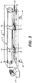
FIGS. 2A to 2B are isometric views of an embodiment of the invention. -
FIG. 3 is a diagrammatic perspective view illustrating the lower column section being inserted into the lower module section. -
FIG. 4 is a partial isometric view of a skirt system in accordance with an embodiment of the present invention. -
FIGS. 5A to 5B are isometric views of an embodiment of the invention. -
FIG. 6 is a partial cross sectional view of a top portion of the upper module section in the vertical position. -
FIG. 7 is an isometric view showing the jacking system installed on the roof of the cold box module. - While the invention will be described in connection with several embodiments, it will be understood that it is not intended to limit the invention to those embodiments. On the contrary, it is intended to cover all the alternatives, modifications and equivalence as may be included within the spirit and scope of the invention defined by the appended claims.
-
FIGS. 1A to 1D show diagrammatically two sections of an air-distillation column approximately 60 meters in length and two sections of its framework, these being constructed for the purpose of implementing the method of construction according to various embodiments of the invention. - A
lower column section 1 and anupper column section 3 of an air-distillation column, of cylindrical general shape, and the correspondinglower module section 5 andupper module section 7 of its framework, of parallelepipedal general shape, are placed approximately horizontally in a workshop. - Each
lower column section 1 andupper column section 3 rests on two spaced-aparttransverse support saddles 9, the longitudinal positions of which with respect to each column half are as described later. Thesesupport saddles 9 are provided withcarriages 11 having rollers with axes approximately orthogonal to the longitudinal axes of each column section. A metalprotective belt 13 goes around each column section at eachsaddle 9. - The lower column section 1 (
FIG. 1B ), which comprises the medium-pressure part and the reboiler, which are not detailed in the figures, is extended, at its lower end (to the left inFIG. 1 ), by askirt system 81.Skirt system 81 is shown in more detail inFIG. 4 . - In one embodiment, the upper column section 3 (
FIG. 1D ) is provided near its upper end (to the right inFIG. 1D ) with means for connecting threaded rods to the upper column section. In the embodiment shown, the means for connected threaded rods can include two symmetrical column supports 23 which are transverse with respect to the longitudinal axis of thehalf 3. These column supports 23 each have ahole 25 whose axis is parallel to the said longitudinal axis, and the rods are held in place using a locking nut. In one embodiment,tabs 23 are primarily used for providing structural support during shipment and are not configured to be able to support the entire weight of the upper column section when in the vertical position. In another embodiment, the fixing tabs can be more structurally robust such that the tabs for the weight of the upper column section in the vertical position. For example, the fixing tabs can be similar in structure to theskirt system 81 as shown inFIG. 4 . - The framework (
FIGS. 1A and 1C ) can include a metal frame comprising fourlongitudinal stanchions 27 connected, on each face of the framework, by cross-members 28 anddiagonal braces 29. The two framework halves (e.g.,upper module section 7 and lower module section 7) each rest on four height-adjustable feet 30.Longitudinal rails 31 are placed on the internal surface of the bottom face (inFIGS. 1A and 1C ) of eachlower module section - The upper end (to the right in
FIG. 1A ) of thelower module section 5 is provided with means for mating with the lower end (to the left inFIG. 1C ) of theupper module section 7. In one embodiment, this means for mating can include atop post 70 for theupper module section 7 and abottom post 72 forlower module section 5. As shown inFIGS. 2A and 2B , the bottom oftop post 70 can be bolted to the top ofbottom post 72. This is preferably achieved using a plurality of boltingplates 74. In a preferred embodiment,top post 70 is not the same thickness asbottom post 72, and therefore,filler plates 76 can be used to allow for thebolting plates 74 to be flush with both thetop post 70 and thebottom post 72. - The top face (to the right in
FIG. 1C ) of theupper module section 7 comprises three approximatelyhorizontal cross-members 35. The bottom andtop cross-members 35 are provided withcentral holes 37 whose axes are parallel to the longitudinal axis of thehalf 7. - The bottom of the lower module section 5 (to the left in
FIG. 1A ) is provided with vertical and horizontal cross-members which delimit, internally to the framework, a region for supporting skirt system 81 (SeeFIG. 4 for more detail). - In one embodiment, to ensure that the longitudinal axis of the
lower module section 5 is horizontal, the height of thefeet 30 are adjusted. This positioning may be checked by using levels or another technique conventional to those skilled in the art. - Next, the
lower column section 1 is introduced into thelower module section 5, by pulling it in by means of awinch 47 connected by a cable to the lower end (to the left inFIG. 3 ) of thehalf 1, thecarriages 11 being made to run along therails 31. In an optional embodiment not shown, instead of using a winch, a set of overhead cranes may also be used to longitudinally insert the column into the framework. In one embodiment not shown, a first carriage and a second carriage are installed inside the cold box structure. The column is transported nearby the opening of the cold box and is preferably aligned with the center line of the cold box. The column is then lifted up, preferably using cranes, and then moved towards the carriages inside of the cold box until one of the support saddles is supported by one of the carriages. The nearest crane is then released. The remaining portion of the column is then slid into further into the cold box, either with the use of the second crane, or by using a flatbed trailer that is adjusted to the appropriate height. The column is again lifted using a crane and slid further into the cold box until the second support saddle can be supported by the second carriage. The two carriages are then moved towards the top of the cold box structure to the appropriate distance. - Once the framework is situation properly within the framework, a set of vertical jacks are used to raise the column by way of the support saddles 9, so that the
carriages 11 can be removed. Once the runners are removed, a structural spacer is placed underneath the support saddles 9 and the cradles are then bolted to the framework. As such, the support saddles 9 and framework provide support against gravitational forces. In a preferred embodiment,temporary saddle spacers 91 can be installed in between the support saddles 9 and the framework. The saddle spacers 91 allow for thesaddles 9 to receive structural support from the framework during shipment, as well as going from horizontal to vertical during installation. Once the cold box is in its vertical orientation, thetemporary saddle spacers 91, can be removed, thereby reducing heat transfer from the cold box framing to the saddles (and in turn, the column). -
FIG. 4 provides an alternative skirt system that can be added to the bottom portion oflower column section 1. This skirt system advantageously prevents the column from buckling during shipment by greatly reducing lateral movement due to acceleration/deceleration. In one embodiment, the skirt system allows for slight movements orthogonal to the longitudinal axis of the column. In the embodiment shown, the skirt system includes a threadedrod 80 secured by atop locking nut 82 and abottom locking nut 84. The top locking nut is attached to atab 86 attached to thelower column section 1, while thebottom locking nut 84 is configured to anchor the rod to the framework 88. As shown, a plurality of threaded rods and locking nuts are used to secure the column to the framework. In the embodiment shown,bracket 85 can be used to secureskirt system 81 to the framework. - The relative positioning of the top
upper column section 3 in the topupper module section 7, in order to assemble the second module, is carried out as follows. - The horizontality of the
upper module section 7 is checked, in a manner similar to that used for thelower module section 5, and then theupper column section 3 is pulled into theupper module section 7 as described for the first module. As mentioned earlier,upper column section 3 differs fromlower column section 1 in thatupper column section 3 is preferably the low pressure column of a double column. As such, during installation,upper column section 3 will need to be lowered ontolower column section 1. While a similar skirt system could be used forupper column section 3 during shipment, this skirt system would provide no additional benefits for loweringupper column section 3 during installation. Therefore, certain embodiments of the invention include a jacking system, which not only provides support during shipment, but can also be used to lowerupper column section 3 ontolower column section 1 afterlower module section FIG. 6 andFIG. 7 . - Means for protecting the open ends of the column, its items of equipment and its framework, for example watertight covers, are then used.
- The upper and lower modules sections are then ready to be transported to an industrial site. The length of these modules, which can be less than 30 m, allow them to be transported by conventional means.
- These module sections can be assembled on site as described below.
- Lifting
lug 60 is bolted onto the top section ofbottom post 72 using a plurality of liftinglug bolting plates 62. In a preferred embodiment, liftinglug 60 is the same thickness asbottom post 72, and therefore, filler plates do not need to be used when bolting liftinglug 60 to thebottom post 72. - The lower module section is lifted using means known in the art (e.g., large crane), and then the bottom of the lower module section 5 (to the left in
FIG. 1A ) can be preferably placed on height-adjustable feet, for example, at the four corners of the framework bottom. The verticality of the longitudinal axis of thelower module section 5 is then checked, for example by means of a sighting device or any other technique conventional to those skilled in the art. - Since the longitudinal axis of the
lower column section 1 is preferably parallel to the longitudinal axis of thelower module section 5, the verticality of thelower column section 1 is easily checked, by modifying the respective height of the feet on which thelower module section 5 rests. - The setting of the lower module section with respect to the ground of the industrial site is then frozen, and then, for example using cranes, the upper module section is placed on top of the lower modules section, and the top post and bottom post are bolted together as shown in
FIGS. 2A and 2B . - In one embodiment, the upper column section is held by four threaded
rods 57 from the jackingsystem 90 located on thecold box roof 100 and the column supports 23 for the rods. In one embodiment, thetop column section 3 is transported in a configuration that is elevated higher than necessary (along the longitudinal axis), thereby providing a space between the top column section and the bottom column section when the two cold box sections are mated. This created space helps to avoid damage to the column sections during assembly on-site. This gap is closed by lowering the top column down slowly. - In another embodiment, the jacking
system 90 is configured to lower the upper column section independent of lowering the upper module section. This advantageously allows for lower installation costs, since a large crane is not needed to make the last portion of high precision lowering. In short, the crane is not needed, since the entire weight of theupper column section 3 is supported by the jackingsystem 90, which in turn is structurally supported by the cold box assembly. - Therefore, once the upper and lower module sections of the cold box module are assembled and secured, the large cranes can be removed and the final column assembly can be done at any time afterwards without the help of any large lifting equipment and with a controlled environment avoiding any risks of weather compromising the on-going operation of the final assembly.
- In one embodiment, the jacking system includes a structural steel assembly installed on the roof of the cold box, and is preferably configured to allow the use of hydraulic jacks to lower the upper column section, which in one embodiment can be supported by four threaded rods, at a rate that it is controlled by the field personnel to make the final column assembly with the lower column section. In one embodiment, the upper section of the top cold box section includes additional structural enhancements (e.g., extra bracing, framing, stiffeners) underneath the location of the hydraulic jacks to accommodate the added stress loads during the lowering of the top column.
-
FIG. 6 provides a side cutaway view of one embodiment of the jackingsystem 90. After the top and bottom cold box assemblies are connected and made vertical, thetemporary saddle spacers 91 can be removed. At this point, the entire weight of theupper column section 3 is now being supported by the jackingsystem 90 androds 57, and theupper column section 3 can now be moved downward. Since the weight of the upper column section is so great (easily can exceed 100 tons), the lowering of the column should be done with great care and control. - In one embodiment, the method for lowering the upper column section independent of the cold box structure can include the steps of providing a plurality of jack lifts 96 on the
roof 100 of the cold box structure and positioning them underneath a liftingframe 94 of the jacking system. The jack lifts 96 are then raised in order to take the weight of the column off of thetemporary shipping spacers 98, and theshipping spacers 98 can then be removed. In a preferred embodiment, shipping spacers are made of steel; however, those of ordinary skill in the art will recognize that any material can be used for the shipping spacers, so long as the shipping spacers can provide the requisite structural strength and support during shipment and erection to vertical position. - The
roof lock nuts 102 are then all equally loosened a predetermined amount, for example a quarter of an inch. The jack lifts 96 are all then lowered until theroof lock nuts 102 are abutting the top of the roof. The jack lifts are then slightly raised to take enough stress off the roof lock nuts so that they can again be loosened the appropriate distance, and the jack lifts are again lowered until the roof lock nuts abut the roof. This process is repeated until the upper column section is appropriately mated with the bottom column. - The column halves 1 and 3 are then welded together, filling the few millimeters provided between the upper and lower column sections with a weld bead. The items of equipment for the bottom module and the top module are connected. In an optional embodiment, the jacking assembly and threaded rods can then be removed from the system and the remaining holes in the roof can be appropriately sealed.
-
FIG. 7 provides an isometric view of the cold box module with jacking system installed on the roof. - In another embodiment, it is also possible to bolt the top cold box assembly to the bottom cold box assembly at the installation site while still in the horizontal position, and then raise the entire cold box assembly to the vertical position in one piece. Overall weight of the cold box assembly and lifting capacity of available cranes can be factors in determining whether the cold box assembly is vertically erected in one or two pieces.
- The method and apparatus according to certain embodiments of the invention therefore allow factory preassembly of a large distillation column and its framework into transportable modules and allows, on site, rapid vertical assembly meeting the verticality constraints imposed on distillation columns.
- As such, embodiments of the invention can improve overall project costs and reduce design and installation time. In preferred embodiments, the invention can have the following advantages:
- Largest and heaviest packages which can be broken into smaller sub-modules or packages without modification of overall conceptual design, manufacturing, transportation, lifting and erection;
- Improve assembly and dis-assembly method to minimize welding on site;
- Employ quick couplings (no welding) for large bore warm end piping for LP circuit, where possible;
- Minimize the needs for scaffolding; and/or
- Packages/Modules completely assembled, instrumented, tested, painted and insulated (where possible) at manufacturing facility
- In another embodiment, the cold box module is an argon cold box, which can include pre-assembly ducts that are configured to be connected to an ASU Cold Box in the field. In another embodiment, the cold box module can include pre-assembled and permanent platforms for both construction and maintenance purposes (depending on the shipping constraints, could be partly dis-assembled), which avoids the use of temporary platforms and scaffolding to complete the connections and for final field assembly.
- In designs known heretofore, the design for both ASU and Argon Cold Boxes was such that all the large safety valves were located at the roof. These safety valves, piping spools and related supports had to be installed in the field at approximately 60 meters (approx 197'-0") height, thereby increasing risks and safety issues associated with working at these height for several days (loss of productivity), necessitating large crane (costs), and requiring the use of diaphragms at the lines penetrating the roof to seal the cold box against the ambient air and humidity including rain, thereby creating an additional risk of water leaking inside the cold box.
- For example, water leaking within the cold box near the top of a cryogenic distillation column could contact the perlite (insulation used within the cold box), causing the perlite to freeze, which reduces the contraction and expansion of these lines penetrating the roof and/or potentially adding weight on theses lines as well as the lines or instrument tubing nearby or located below the icing formation. In certain embodiments of the invention, these problems are reduced and/or eliminated.
- By relocating the various valves at a lower platform area, safety risks are minimized, usage of cranes is reduced, water leakage is reduced, and there are greatly reduced problems associated with freezing.
Claims (14)
- A method for installation of a cryogenic distillation apparatus, the method comprising the steps of:• providing an upper module section (7) having an upper column section (3) disposed within and secured to the upper module section, wherein the upper module comprises a roof (100);• providing a lower module section (5) having a lower column section (1) disposed within and secured to the lower module section;• erecting the lower module section from a horizontal position to a vertical position at an installation site;• lifting the upper module section from a horizontal position and attaching the upper module section, while in a vertical position, to a top portion of the lower module section;• lowering the upper column section, independent of the upper module section, toward the lower column section; and• welding the upper column section and the lower column section together.
- The method as claimed in Claim 1, further comprising the step of transporting the upper module section (7) and the lower module section (5) separately to the installation site prior to erecting the lower module section at the installation site.
- The method as claimed in Claim 11, wherein the step of lowering the upper column section (3), independent of the upper module section (7), toward the lower column section (1) further comprises the steps of: positioning a plurality of lift jacks (96) on the roof (100) of the lower column section and underneath a lifting frame (94) of a jacking system, wherein the lifting frame supports the upper column section via a plurality of suspension rods (57); raising the lift jacks in order to take the weight of the upper column section off of a plurality of shipping spacers (98); and removing the shipping spacers.
- The method as claimed in Claim 3, wherein the step of lowering the upper column section (3), independent of the upper module section (7), toward the lower column section (1) further comprises the steps of: (a) loosening a set of roof lock nuts (102) a predetermined amount; (b) lowering the lift jacks (96) until the roof lock nuts abut the top of the roof (100); and (c) repeating steps (a) and (b) until the upper column section has been lowered an acceptable distance for welding the upper column section and the lower column section together.
- The method as claimed in Claim 1, wherein the upper module section (7) further comprises a jacking system (90) disposed on the roof of the upper module section.
- The method as claimed in Claim 5, wherein the jacking system comprises:• a structural assembly; and• a plurality of suspension rods (57) supported at an upper end by the structural assembly, wherein the plurality of suspension rods is configured to provide support to the upper column section (3).
- The method as claimed in Claim 6, wherein the structural assembly further comprises:a lifting frame (94) elevated from the roof (100);means for lowering the upper column section (3) in a controlled manner (96, 102); anda plurality of shipping spacers (98) disposed between the lifting frame (94) and the roof of the cold box.
- The method as claimed in Claim 7, further comprising the step of removing the shipping spacers (98) after the upper module section (7) and the lower module section (5) are attached and before the upper column section (3) is lowered, independent of the upper module section, toward the lower column section.
- The method as claimed in Claim 7, wherein the means for lowering the upper column section in a controlled manner comprise a set of roof lock nuts (102) engaged with the plurality of suspension rods (57), wherein the roof lock nuts are configured to provide a set stopping point for lowering the upper column section (3).
- The method as claimed in Claim 7, further comprising means for elevating the lifting frame (94) off the plurality of shipping spacers (98).
- The method as claimed in Claim 10, wherein the means for elevating the lifting frame (94) from shipping spacers (98) comprises a plurality of hydraulic lift jacks (96).
- The method as claimed in Claim 6, wherein column supports (23) are disposed on the upper column section, wherein the column supports are configured to engage with the suspension rods (57) and transfer the weight of the upper column section (3) to the suspension rods.
- The method as claimed in Claim 6, further comprising the steps of removing the jacking system (90) and sealing any access holes on the roof (100).
- A method for installation of a cryogenic distillation apparatus, the method comprising the steps of:• providing an upper module section (7) having an upper column section (3) disposed within and secured to the upper module section, wherein the upper module comprises a roof (100);• providing a lower module section (5) having a lower column section (1) disposed within and secured to the lower module section;• connecting the lower module section and the upper module section together while in a horizontal position to form a cold box module, wherein there is a defined gap between a bottom of the upper column section and a top of the lower column section;• erecting the cold box module from the horizontal position to a vertical position at an installation site;• lowering the upper column section, independent of the upper module section, toward the lower column section; and• welding the upper column section and the lower column section together.
Applications Claiming Priority (3)
| Application Number | Priority Date | Filing Date | Title |
|---|---|---|---|
| US201762484561P | 2017-04-12 | 2017-04-12 | |
| EP18722308.6A EP3610211B1 (en) | 2017-04-12 | 2018-04-12 | A method for constructing a cold box module and resulting apparatus |
| PCT/US2018/027345 WO2018191526A1 (en) | 2017-04-12 | 2018-04-12 | A method for constructing a cold box module and resulting apparatus |
Related Parent Applications (2)
| Application Number | Title | Priority Date | Filing Date |
|---|---|---|---|
| EP18722308.6A Division EP3610211B1 (en) | 2017-04-12 | 2018-04-12 | A method for constructing a cold box module and resulting apparatus |
| EP18722308.6A Division-Into EP3610211B1 (en) | 2017-04-12 | 2018-04-12 | A method for constructing a cold box module and resulting apparatus |
Publications (2)
| Publication Number | Publication Date |
|---|---|
| EP3995770A2 true EP3995770A2 (en) | 2022-05-11 |
| EP3995770A3 EP3995770A3 (en) | 2022-08-10 |
Family
ID=62111215
Family Applications (3)
| Application Number | Title | Priority Date | Filing Date |
|---|---|---|---|
| EP18722308.6A Active EP3610211B1 (en) | 2017-04-12 | 2018-04-12 | A method for constructing a cold box module and resulting apparatus |
| EP21211483.9A Withdrawn EP3995770A3 (en) | 2017-04-12 | 2018-04-12 | A method for installation of a cryogenic distillation apparatus |
| EP21211481.3A Active EP3995769B1 (en) | 2017-04-12 | 2018-04-12 | A jacking system for use in lowering an upper column section |
Family Applications Before (1)
| Application Number | Title | Priority Date | Filing Date |
|---|---|---|---|
| EP18722308.6A Active EP3610211B1 (en) | 2017-04-12 | 2018-04-12 | A method for constructing a cold box module and resulting apparatus |
Family Applications After (1)
| Application Number | Title | Priority Date | Filing Date |
|---|---|---|---|
| EP21211481.3A Active EP3995769B1 (en) | 2017-04-12 | 2018-04-12 | A jacking system for use in lowering an upper column section |
Country Status (4)
| Country | Link |
|---|---|
| US (4) | US10746462B2 (en) |
| EP (3) | EP3610211B1 (en) |
| CN (1) | CN110709660B (en) |
| WO (1) | WO2018191526A1 (en) |
Families Citing this family (10)
| Publication number | Priority date | Publication date | Assignee | Title |
|---|---|---|---|---|
| US10746462B2 (en) * | 2017-04-12 | 2020-08-18 | L'air Liquide Societe Anonyme Pour L'etude Et L'explotation Des Procedes Georges Claude | Method for constructing a cold box module |
| CN109455418A (en) * | 2018-12-17 | 2019-03-12 | 乔治洛德方法研究和开发液化空气有限公司 | A kind of ice chest steel construction and method that is prefabricated and transporting the ice chest steel construction |
| FR3095217B1 (en) * | 2019-04-17 | 2021-03-19 | Air Liquide | Frame panel intended to be part of a cold box of a separation device |
| FR3096442B1 (en) * | 2019-05-22 | 2021-05-21 | Air Liquide | Thermally insulated enclosure containing equipment that must operate at a temperature below 0 ° C |
| EP4166877B8 (en) * | 2019-10-08 | 2026-02-25 | Honeywell LNG LLC | Heat exchange system and method of assembly |
| FR3111968B1 (en) | 2020-06-30 | 2022-05-20 | Air Liquide | Thermally insulated enclosure for a cryogenic distillation apparatus and method for transporting and constructing such an enclosure |
| CN112192503A (en) * | 2020-09-02 | 2021-01-08 | 江苏利柏特股份有限公司 | Installation method for installing tower in cold box |
| FR3118453B1 (en) * | 2020-12-24 | 2023-03-24 | Air Liquide | Enclosure and method for constructing an enclosure of a cryogenic distillation separation apparatus |
| CN114017991A (en) * | 2021-11-05 | 2022-02-08 | 上海二十冶建设有限公司 | Installation and adjustment method for tower in modular cold box |
| FR3141512B1 (en) * | 2023-06-29 | 2024-09-20 | Air Liquide | Cold box |
Family Cites Families (69)
| Publication number | Priority date | Publication date | Assignee | Title |
|---|---|---|---|---|
| US3155265A (en) * | 1964-11-03 | Thermal stress equalizing support system | ||
| US1587689A (en) * | 1926-01-19 | 1926-06-08 | Oscar J Weiss | Device for applying flexible pipe connections |
| US1866517A (en) * | 1926-11-13 | 1932-07-05 | Fluga Ag | Transportation or pressure vessel for gases |
| US1910138A (en) * | 1928-12-29 | 1933-05-23 | Henry Van Hooydonk | Reenforced pipe construction and method of setting |
| US2167338A (en) * | 1937-07-26 | 1939-07-25 | U C Murcell Inc | Welding and setting well casing |
| US2587204A (en) * | 1946-05-21 | 1952-02-26 | Union Carbide & Carbon Corp | Railroad tank car |
| US2592974A (en) * | 1949-07-01 | 1952-04-15 | Gerard F Sulfrian | Suspension liquid gas container |
| US2814410A (en) * | 1954-06-24 | 1957-11-26 | Union Carbide Corp | Double wall tank |
| US2890009A (en) * | 1955-07-13 | 1959-06-09 | Combustion Eng | Vessel support |
| US2926810A (en) * | 1956-10-30 | 1960-03-01 | Herrick L Johnston Inc | Suspension system for container for storing liquefied gas |
| US2968410A (en) * | 1956-11-28 | 1961-01-17 | Cleveland Pneumatic Ind Inc | Towers |
| US3021027A (en) * | 1958-10-08 | 1962-02-13 | David R Claxton | Means for supporting the inner member of a double-walled tank |
| NL123988C (en) * | 1959-12-07 | |||
| BE607357A (en) * | 1960-09-12 | 1900-01-01 | ||
| US3163313A (en) * | 1962-12-17 | 1964-12-29 | Cryogenic Eng Co | Mobile dewar assembly for transport of cryogenic fluids |
| US3750413A (en) * | 1968-10-15 | 1973-08-07 | Hydrocarbon Research Inc | Cryogenic apparatus assembly method |
| US3673754A (en) * | 1969-07-18 | 1972-07-04 | Kawatetsu Kizai Kogyo Co | Lift up process |
| US3692206A (en) * | 1969-09-02 | 1972-09-19 | Air Prod & Chem | Suspension system for multiwalled containers |
| US3782128A (en) * | 1970-06-01 | 1974-01-01 | Lox Equip | Cryogenic storage vessel |
| US3764036A (en) * | 1970-12-02 | 1973-10-09 | Ametek Inc | Cryogenic liquid storage systems |
| US3688840A (en) * | 1971-02-16 | 1972-09-05 | Cameron Iron Works Inc | Method and apparatus for use in drilling a well |
| AT322301B (en) * | 1971-06-15 | 1975-05-12 | Kabel Metallwerke Ghh | PIPE SYSTEM CONSISING OF AT LEAST TWO CONCENTRIC PIPES |
| US3768765A (en) * | 1972-02-14 | 1973-10-30 | Little Inc A | Thermally isolating structural support system and cryogenic assembly embodying the same |
| US3711920A (en) * | 1972-03-02 | 1973-01-23 | R Simmons | Pipe puller and alignment clamp |
| US3814361A (en) * | 1972-09-29 | 1974-06-04 | Little Inc A | Dual-mode cryogenic support system |
| JPS5249775Y2 (en) * | 1973-08-30 | 1977-11-11 | ||
| DE2457264C2 (en) * | 1974-12-04 | 1977-01-13 | Linde Ag | VACUUM-INSULATED STORAGE OR TRANSPORT CONTAINER FOR LOW-BOILING LIQUID GASES |
| DE2548356C2 (en) * | 1975-10-29 | 1982-11-11 | Westerwälder Eisenwerk Gerhard GmbH, 5241 Weitefeld | Double-walled transport container for liquids and gases |
| US4141130A (en) * | 1977-12-05 | 1979-02-27 | H. C. Price Co. | Method and apparatus for centering two concentric cylinders |
| US4291541A (en) * | 1978-02-21 | 1981-09-29 | Varian Associates, Inc. | Cryostat with external refrigerator for super-conducting NMR spectrometer |
| US4209891A (en) * | 1978-07-17 | 1980-07-01 | Nl Industries, Inc. | Apparatus and method for positioning one part relative to another part |
| US4259776A (en) * | 1978-08-09 | 1981-04-07 | Airships International Inc. | Method of assembly of airship hull |
| US4184609A (en) * | 1978-08-22 | 1980-01-22 | The United States Of America As Represented By The Administrator Of The National Aeronautics And Space Administration | Cryogenic container compound suspension strap |
| DE2903787C2 (en) * | 1979-02-01 | 1983-11-03 | Messerschmitt-Bölkow-Blohm GmbH, 8000 München | Suspension device for a low-temperature tank arranged in a thermally insulated manner in an external container |
| US4295526A (en) * | 1979-02-21 | 1981-10-20 | Service Equipment Design Co., Inc. | Method and apparatus for connecting steel pipe sections |
| US4426819A (en) * | 1980-12-10 | 1984-01-24 | Dyar Harrison G | Thermal insulating system particularly adapted for building construction |
| US4462535A (en) * | 1981-04-23 | 1984-07-31 | Amca International Corporation | Apparatus and process for manufacture of tunnel tubes |
| US4500078A (en) * | 1983-01-03 | 1985-02-19 | Brennan Gerald J | Chimney flue insertion apparatus |
| US4481778A (en) * | 1983-03-21 | 1984-11-13 | Ball Corporation | Thermally disconnecting passive parallel orbital supports |
| US4547096A (en) * | 1983-08-01 | 1985-10-15 | Mcdermott International, Inc. | Alignment of tubular piles for joinder |
| US4696169A (en) * | 1986-05-15 | 1987-09-29 | The United States Of America As Represented By The United States Department Of Energy | Cryogenic support member |
| US4848103A (en) * | 1987-04-02 | 1989-07-18 | General Electric Company | Radial cryostat suspension system |
| US4821907A (en) * | 1988-06-13 | 1989-04-18 | The United States Of America As Represented By The Administrator Of The National Aeronautics And Space Administration | Surface tension confined liquid cryogen cooler |
| US5012948A (en) * | 1989-06-21 | 1991-05-07 | General Dynamics Corporation, Convair Division | Support arrangement for a space based cryogenic vessel |
| US5081761A (en) * | 1990-04-17 | 1992-01-21 | Rinehart Ronald K | Double wall steel tank |
| JP3102492B2 (en) * | 1990-07-20 | 2000-10-23 | 株式会社日立製作所 | Anti-vibration cryostat |
| US5246068A (en) * | 1991-06-12 | 1993-09-21 | Ronald Besson | Apparatus for removing a wellhead cover from a well |
| US5595319A (en) * | 1991-06-26 | 1997-01-21 | Nuclear Containers, Inc., A Tennesse Corporation | Reusable container unit having spaced protective housings |
| EP0591447B1 (en) * | 1991-06-26 | 1998-05-20 | HOUSEHOLDER, William R. | Reusable container unit |
| FR2692663B1 (en) * | 1992-06-17 | 1994-08-19 | Air Liquide | Method for constructing a cryogenic gas separation unit, cryogenic unit, subassembly and transportable assembly for the construction of such a unit. |
| DE4227189A1 (en) * | 1992-08-17 | 1994-02-24 | Linde Ag | Storage tank holder |
| US5650230A (en) * | 1993-01-15 | 1997-07-22 | Wisconsin Alumni Research Foundation | Compressive strut for cryogenic applications |
| US5385026A (en) * | 1993-03-04 | 1995-01-31 | The United States Of America As Represented By The United States Department Of Energy | Apparatus for supporting a cryogenic fluid containment system within an enclosure |
| US5649402A (en) * | 1995-09-01 | 1997-07-22 | Fwt, Inc. | Antenna support for power transmission tower |
| US5657526A (en) * | 1995-12-15 | 1997-08-19 | Yatcko; Michael J. | Split riding ring for rotary cylinders |
| FR2769656B1 (en) * | 1997-10-14 | 1999-12-17 | Air Liquide | METHOD FOR MAKING A PACKAGE BY ASSEMBLING AN INTERIOR STRUCTURE FOR CONTAINING FLUID, AN OUTSIDE STRUCTURE AND EQUIPMENT, AND METHOD FOR CONSTRUCTION ON SITE USING SUCH A PACKAGE |
| FR2775439B1 (en) * | 1997-10-14 | 2000-04-14 | Air Liquide | METHOD FOR CONSTRUCTING AN INTERIOR STRUCTURE FOR CONTAINING AN ELONGATED FLUID, LARGE DIMENSIONS, AND SURROUNDED BY AN EXTERNAL STRUCTURE |
| FR2778233B1 (en) * | 1998-04-30 | 2000-06-02 | Air Liquide | AIR DISTILLATION SYSTEM AND CORRESPONDING COLD BOX |
| DE10319755A1 (en) * | 2003-04-30 | 2004-11-18 | Linde Ag | Column system and method for its production |
| US20070256391A1 (en) * | 2006-04-14 | 2007-11-08 | Mifsud Vincent D | Framing table for building panel assembly |
| US8511632B2 (en) * | 2011-01-06 | 2013-08-20 | General Electric Company | Suspension system and method for suspending an inner vessel inside an outer vessel of a cryostat |
| AU2013101347B4 (en) | 2012-10-18 | 2014-07-03 | Merhi, Khalil Nasser | Methods, systems and components for multi-storey building construction |
| HUE048830T2 (en) * | 2013-04-05 | 2020-08-28 | Cryoshelter Gmbh | Suspension device for a thermally isolated inner container arranged in an outer container and container assembly |
| US9550593B2 (en) * | 2013-05-24 | 2017-01-24 | L'Air Liquide Société Anonyme Pour L'Étude Et L'Exploitation Des Procedes Georges Claude | Scaffolding assembly |
| US9261237B2 (en) * | 2014-01-30 | 2016-02-16 | Lockheed Martin Corporation | Keyway retention system for cryogenic storage tanks |
| CN103938856B (en) * | 2014-04-09 | 2015-09-02 | 中国化学工程第十三建设有限公司 | A kind of tower-like structure are without support bar slding form operation operating platform and construction method |
| CN105781205B (en) * | 2015-11-30 | 2018-02-06 | 中国化学工程第三建设有限公司 | A kind of guider in place of the aerial group pair of heavy tower equipment segmental hoisting |
| FR3035487A3 (en) * | 2016-07-29 | 2016-10-28 | Air Liquide | APPARATUS FOR ADJUSTING THE POSITIONING OF A DISTILLATION COLUMN |
| US10746462B2 (en) * | 2017-04-12 | 2020-08-18 | L'air Liquide Societe Anonyme Pour L'etude Et L'explotation Des Procedes Georges Claude | Method for constructing a cold box module |
-
2018
- 2018-04-12 US US15/952,023 patent/US10746462B2/en active Active
- 2018-04-12 EP EP18722308.6A patent/EP3610211B1/en active Active
- 2018-04-12 EP EP21211483.9A patent/EP3995770A3/en not_active Withdrawn
- 2018-04-12 EP EP21211481.3A patent/EP3995769B1/en active Active
- 2018-04-12 US US15/952,033 patent/US10753681B2/en active Active
- 2018-04-12 US US15/952,030 patent/US10739068B2/en active Active
- 2018-04-12 CN CN201880038057.7A patent/CN110709660B/en active Active
- 2018-04-12 US US15/952,016 patent/US10914518B2/en active Active
- 2018-04-12 WO PCT/US2018/027345 patent/WO2018191526A1/en not_active Ceased
Also Published As
| Publication number | Publication date |
|---|---|
| WO2018191526A1 (en) | 2018-10-18 |
| EP3610211A1 (en) | 2020-02-19 |
| US10753681B2 (en) | 2020-08-25 |
| CN110709660B (en) | 2022-04-19 |
| US20180299198A1 (en) | 2018-10-18 |
| US10739068B2 (en) | 2020-08-11 |
| US20180299197A1 (en) | 2018-10-18 |
| EP3995770A3 (en) | 2022-08-10 |
| US20180299199A1 (en) | 2018-10-18 |
| US10914518B2 (en) | 2021-02-09 |
| US20180299196A1 (en) | 2018-10-18 |
| CN110709660A (en) | 2020-01-17 |
| EP3610211B1 (en) | 2024-05-29 |
| US10746462B2 (en) | 2020-08-18 |
| EP3995769A1 (en) | 2022-05-11 |
| EP3995769B1 (en) | 2024-05-29 |
Similar Documents
| Publication | Publication Date | Title |
|---|---|---|
| EP3610211B1 (en) | A method for constructing a cold box module and resulting apparatus | |
| US20150308140A1 (en) | Modular monopole tower foundation | |
| US9285164B2 (en) | Cold box sheet metal jacket | |
| CA2249888C (en) | Method of producing a package of internal and external structures and of items of equipment, and method of on-site construction using such a package | |
| CN110512910B (en) | Integral heightening and mounting method for high-span steel structure of steel-making main plant | |
| CN115917672A (en) | Modular fabrication, delivery and assembly of nuclear reactor building systems | |
| US11428466B2 (en) | Cold box steel structure and method for prefabricating and transporting same | |
| US8573564B2 (en) | Lifting system and method for lifting bulk sized, high weight objects | |
| CN111395850A (en) | A prefabricated tower and erection method for a cable hoisting system | |
| US20180209727A1 (en) | Structual support assembly for cold box structures in an air separation unit | |
| CN114960731B (en) | Pre-buried nested combined tower crane section foundation and construction method | |
| CN115030522A (en) | Construction method of large steel structure | |
| CN106223669A (en) | A kind of space division packaging type ice chest | |
| CN211666205U (en) | A steel structure module retractable device | |
| WO2025246744A1 (en) | Steel box girder hoisting process | |
| CN113137102A (en) | Assembled type warehouse roof structure and installation method thereof | |
| US20220205716A1 (en) | Enclosure and method for constructing an enclosure of an apparatus for separation by cryogenic distillation | |
| KR101258330B1 (en) | Temporary supporting system of steel beam and construstion method thereof | |
| JP7058892B1 (en) | Steel structure constructed around the existing columnar body and its construction method | |
| CN110948192A (en) | Crane tripod assembling method | |
| CN217225504U (en) | Nuclear power station emergency gate head storage device | |
| JP7832415B2 (en) | Equipment installation modular unit | |
| CN116201132A (en) | Main support applied to foundation pit engineering |
Legal Events
| Date | Code | Title | Description |
|---|---|---|---|
| PUAI | Public reference made under article 153(3) epc to a published international application that has entered the european phase |
Free format text: ORIGINAL CODE: 0009012 |
|
| STAA | Information on the status of an ep patent application or granted ep patent |
Free format text: STATUS: THE APPLICATION HAS BEEN PUBLISHED |
|
| AC | Divisional application: reference to earlier application |
Ref document number: 3610211 Country of ref document: EP Kind code of ref document: P |
|
| AK | Designated contracting states |
Kind code of ref document: A2 Designated state(s): AL AT BE BG CH CY CZ DE DK EE ES FI FR GB GR HR HU IE IS IT LI LT LU LV MC MK MT NL NO PL PT RO RS SE SI SK SM TR |
|
| PUAL | Search report despatched |
Free format text: ORIGINAL CODE: 0009013 |
|
| AK | Designated contracting states |
Kind code of ref document: A3 Designated state(s): AL AT BE BG CH CY CZ DE DK EE ES FI FR GB GR HR HU IE IS IT LI LT LU LV MC MK MT NL NO PL PT RO RS SE SI SK SM TR |
|
| RIC1 | Information provided on ipc code assigned before grant |
Ipc: E04H 5/10 20060101ALI20220706BHEP Ipc: F25J 3/04 20060101AFI20220706BHEP |
|
| STAA | Information on the status of an ep patent application or granted ep patent |
Free format text: STATUS: THE APPLICATION HAS BEEN WITHDRAWN |
|
| 18W | Application withdrawn |
Effective date: 20221206 |