EP3995685B1 - Method for diagnosing an air flowmeter for an internal combustion engine - Google Patents
Method for diagnosing an air flowmeter for an internal combustion engine Download PDFInfo
- Publication number
- EP3995685B1 EP3995685B1 EP21204628.8A EP21204628A EP3995685B1 EP 3995685 B1 EP3995685 B1 EP 3995685B1 EP 21204628 A EP21204628 A EP 21204628A EP 3995685 B1 EP3995685 B1 EP 3995685B1
- Authority
- EP
- European Patent Office
- Prior art keywords
- value
- engine
- flow rate
- threshold
- flowmeter
- Prior art date
- Legal status (The legal status is an assumption and is not a legal conclusion. Google has not performed a legal analysis and makes no representation as to the accuracy of the status listed.)
- Active
Links
- 238000000034 method Methods 0.000 title claims description 33
- 238000002485 combustion reaction Methods 0.000 title claims description 14
- 239000007789 gas Substances 0.000 claims description 91
- 239000000446 fuel Substances 0.000 claims description 51
- 238000003745 diagnosis Methods 0.000 claims description 43
- 238000011144 upstream manufacturing Methods 0.000 claims description 28
- QVGXLLKOCUKJST-UHFFFAOYSA-N atomic oxygen Chemical compound [O] QVGXLLKOCUKJST-UHFFFAOYSA-N 0.000 claims description 20
- 239000001301 oxygen Substances 0.000 claims description 20
- 229910052760 oxygen Inorganic materials 0.000 claims description 20
- 238000012937 correction Methods 0.000 claims description 12
- 238000004064 recycling Methods 0.000 claims description 5
- 230000001105 regulatory effect Effects 0.000 claims description 4
- 238000002347 injection Methods 0.000 claims description 2
- 239000007924 injection Substances 0.000 claims description 2
- 230000001276 controlling effect Effects 0.000 claims 1
- MWUXSHHQAYIFBG-UHFFFAOYSA-N nitrogen oxide Inorganic materials O=[N] MWUXSHHQAYIFBG-UHFFFAOYSA-N 0.000 description 34
- 239000000523 sample Substances 0.000 description 16
- 239000003054 catalyst Substances 0.000 description 13
- 239000000203 mixture Substances 0.000 description 10
- 230000008569 process Effects 0.000 description 7
- 238000005259 measurement Methods 0.000 description 6
- 239000000567 combustion gas Substances 0.000 description 5
- 230000006870 function Effects 0.000 description 5
- 239000002245 particle Substances 0.000 description 5
- 238000005520 cutting process Methods 0.000 description 4
- 238000002405 diagnostic procedure Methods 0.000 description 4
- 238000010926 purge Methods 0.000 description 4
- 238000012544 monitoring process Methods 0.000 description 3
- 230000008929 regeneration Effects 0.000 description 3
- 238000011069 regeneration method Methods 0.000 description 3
- 238000012360 testing method Methods 0.000 description 3
- 239000002699 waste material Substances 0.000 description 3
- 230000008901 benefit Effects 0.000 description 2
- 238000001514 detection method Methods 0.000 description 2
- 230000000694 effects Effects 0.000 description 2
- 230000003647 oxidation Effects 0.000 description 2
- 238000007254 oxidation reaction Methods 0.000 description 2
- 230000009467 reduction Effects 0.000 description 2
- 238000006722 reduction reaction Methods 0.000 description 2
- 239000004071 soot Substances 0.000 description 2
- 230000000903 blocking effect Effects 0.000 description 1
- 238000010531 catalytic reduction reaction Methods 0.000 description 1
- 230000008859 change Effects 0.000 description 1
- 230000006835 compression Effects 0.000 description 1
- 238000007906 compression Methods 0.000 description 1
- 230000007547 defect Effects 0.000 description 1
- 238000011161 development Methods 0.000 description 1
- 230000018109 developmental process Effects 0.000 description 1
- 238000006073 displacement reaction Methods 0.000 description 1
- 238000009826 distribution Methods 0.000 description 1
- TXKMVPPZCYKFAC-UHFFFAOYSA-N disulfur monoxide Inorganic materials O=S=S TXKMVPPZCYKFAC-UHFFFAOYSA-N 0.000 description 1
- 238000004519 manufacturing process Methods 0.000 description 1
- 230000001172 regenerating effect Effects 0.000 description 1
- 230000004044 response Effects 0.000 description 1
- 230000035945 sensitivity Effects 0.000 description 1
- XTQHKBHJIVJGKJ-UHFFFAOYSA-N sulfur monoxide Chemical compound S=O XTQHKBHJIVJGKJ-UHFFFAOYSA-N 0.000 description 1
- 238000012546 transfer Methods 0.000 description 1
- 230000001052 transient effect Effects 0.000 description 1
Images


Classifications
-
- F—MECHANICAL ENGINEERING; LIGHTING; HEATING; WEAPONS; BLASTING
- F02—COMBUSTION ENGINES; HOT-GAS OR COMBUSTION-PRODUCT ENGINE PLANTS
- F02D—CONTROLLING COMBUSTION ENGINES
- F02D41/00—Electrical control of supply of combustible mixture or its constituents
- F02D41/02—Circuit arrangements for generating control signals
- F02D41/18—Circuit arrangements for generating control signals by measuring intake air flow
-
- F—MECHANICAL ENGINEERING; LIGHTING; HEATING; WEAPONS; BLASTING
- F02—COMBUSTION ENGINES; HOT-GAS OR COMBUSTION-PRODUCT ENGINE PLANTS
- F02D—CONTROLLING COMBUSTION ENGINES
- F02D41/00—Electrical control of supply of combustible mixture or its constituents
- F02D41/0025—Controlling engines characterised by use of non-liquid fuels, pluralities of fuels, or non-fuel substances added to the combustible mixtures
- F02D41/0047—Controlling exhaust gas recirculation [EGR]
- F02D41/005—Controlling exhaust gas recirculation [EGR] according to engine operating conditions
- F02D41/0055—Special engine operating conditions, e.g. for regeneration of exhaust gas treatment apparatus
-
- F—MECHANICAL ENGINEERING; LIGHTING; HEATING; WEAPONS; BLASTING
- F02—COMBUSTION ENGINES; HOT-GAS OR COMBUSTION-PRODUCT ENGINE PLANTS
- F02D—CONTROLLING COMBUSTION ENGINES
- F02D41/00—Electrical control of supply of combustible mixture or its constituents
- F02D41/22—Safety or indicating devices for abnormal conditions
- F02D41/222—Safety or indicating devices for abnormal conditions relating to the failure of sensors or parameter detection devices
-
- F—MECHANICAL ENGINEERING; LIGHTING; HEATING; WEAPONS; BLASTING
- F02—COMBUSTION ENGINES; HOT-GAS OR COMBUSTION-PRODUCT ENGINE PLANTS
- F02M—SUPPLYING COMBUSTION ENGINES IN GENERAL WITH COMBUSTIBLE MIXTURES OR CONSTITUENTS THEREOF
- F02M26/00—Engine-pertinent apparatus for adding exhaust gases to combustion-air, main fuel or fuel-air mixture, e.g. by exhaust gas recirculation [EGR] systems
- F02M26/02—EGR systems specially adapted for supercharged engines
- F02M26/04—EGR systems specially adapted for supercharged engines with a single turbocharger
- F02M26/05—High pressure loops, i.e. wherein recirculated exhaust gas is taken out from the exhaust system upstream of the turbine and reintroduced into the intake system downstream of the compressor
-
- F—MECHANICAL ENGINEERING; LIGHTING; HEATING; WEAPONS; BLASTING
- F02—COMBUSTION ENGINES; HOT-GAS OR COMBUSTION-PRODUCT ENGINE PLANTS
- F02M—SUPPLYING COMBUSTION ENGINES IN GENERAL WITH COMBUSTIBLE MIXTURES OR CONSTITUENTS THEREOF
- F02M26/00—Engine-pertinent apparatus for adding exhaust gases to combustion-air, main fuel or fuel-air mixture, e.g. by exhaust gas recirculation [EGR] systems
- F02M26/02—EGR systems specially adapted for supercharged engines
- F02M26/04—EGR systems specially adapted for supercharged engines with a single turbocharger
- F02M26/06—Low pressure loops, i.e. wherein recirculated exhaust gas is taken out from the exhaust downstream of the turbocharger turbine and reintroduced into the intake system upstream of the compressor
-
- F—MECHANICAL ENGINEERING; LIGHTING; HEATING; WEAPONS; BLASTING
- F02—COMBUSTION ENGINES; HOT-GAS OR COMBUSTION-PRODUCT ENGINE PLANTS
- F02M—SUPPLYING COMBUSTION ENGINES IN GENERAL WITH COMBUSTIBLE MIXTURES OR CONSTITUENTS THEREOF
- F02M35/00—Combustion-air cleaners, air intakes, intake silencers, or induction systems specially adapted for, or arranged on, internal-combustion engines
- F02M35/10—Air intakes; Induction systems
- F02M35/10373—Sensors for intake systems
- F02M35/1038—Sensors for intake systems for temperature or pressure
-
- F—MECHANICAL ENGINEERING; LIGHTING; HEATING; WEAPONS; BLASTING
- F02—COMBUSTION ENGINES; HOT-GAS OR COMBUSTION-PRODUCT ENGINE PLANTS
- F02M—SUPPLYING COMBUSTION ENGINES IN GENERAL WITH COMBUSTIBLE MIXTURES OR CONSTITUENTS THEREOF
- F02M35/00—Combustion-air cleaners, air intakes, intake silencers, or induction systems specially adapted for, or arranged on, internal-combustion engines
- F02M35/10—Air intakes; Induction systems
- F02M35/10373—Sensors for intake systems
- F02M35/10386—Sensors for intake systems for flow rate
-
- F—MECHANICAL ENGINEERING; LIGHTING; HEATING; WEAPONS; BLASTING
- F02—COMBUSTION ENGINES; HOT-GAS OR COMBUSTION-PRODUCT ENGINE PLANTS
- F02D—CONTROLLING COMBUSTION ENGINES
- F02D2200/00—Input parameters for engine control
- F02D2200/02—Input parameters for engine control the parameters being related to the engine
- F02D2200/04—Engine intake system parameters
- F02D2200/0402—Engine intake system parameters the parameter being determined by using a model of the engine intake or its components
-
- F—MECHANICAL ENGINEERING; LIGHTING; HEATING; WEAPONS; BLASTING
- F02—COMBUSTION ENGINES; HOT-GAS OR COMBUSTION-PRODUCT ENGINE PLANTS
- F02D—CONTROLLING COMBUSTION ENGINES
- F02D41/00—Electrical control of supply of combustible mixture or its constituents
- F02D41/0025—Controlling engines characterised by use of non-liquid fuels, pluralities of fuels, or non-fuel substances added to the combustible mixtures
- F02D41/0047—Controlling exhaust gas recirculation [EGR]
- F02D41/0065—Specific aspects of external EGR control
- F02D41/0072—Estimating, calculating or determining the EGR rate, amount or flow
-
- F—MECHANICAL ENGINEERING; LIGHTING; HEATING; WEAPONS; BLASTING
- F02—COMBUSTION ENGINES; HOT-GAS OR COMBUSTION-PRODUCT ENGINE PLANTS
- F02D—CONTROLLING COMBUSTION ENGINES
- F02D41/00—Electrical control of supply of combustible mixture or its constituents
- F02D41/02—Circuit arrangements for generating control signals
- F02D41/04—Introducing corrections for particular operating conditions
- F02D41/12—Introducing corrections for particular operating conditions for deceleration
- F02D41/123—Introducing corrections for particular operating conditions for deceleration the fuel injection being cut-off
-
- F—MECHANICAL ENGINEERING; LIGHTING; HEATING; WEAPONS; BLASTING
- F02—COMBUSTION ENGINES; HOT-GAS OR COMBUSTION-PRODUCT ENGINE PLANTS
- F02M—SUPPLYING COMBUSTION ENGINES IN GENERAL WITH COMBUSTIBLE MIXTURES OR CONSTITUENTS THEREOF
- F02M26/00—Engine-pertinent apparatus for adding exhaust gases to combustion-air, main fuel or fuel-air mixture, e.g. by exhaust gas recirculation [EGR] systems
- F02M26/13—Arrangement or layout of EGR passages, e.g. in relation to specific engine parts or for incorporation of accessories
- F02M26/35—Arrangement or layout of EGR passages, e.g. in relation to specific engine parts or for incorporation of accessories with means for cleaning or treating the recirculated gases, e.g. catalysts, condensate traps, particle filters or heaters
-
- Y—GENERAL TAGGING OF NEW TECHNOLOGICAL DEVELOPMENTS; GENERAL TAGGING OF CROSS-SECTIONAL TECHNOLOGIES SPANNING OVER SEVERAL SECTIONS OF THE IPC; TECHNICAL SUBJECTS COVERED BY FORMER USPC CROSS-REFERENCE ART COLLECTIONS [XRACs] AND DIGESTS
- Y02—TECHNOLOGIES OR APPLICATIONS FOR MITIGATION OR ADAPTATION AGAINST CLIMATE CHANGE
- Y02T—CLIMATE CHANGE MITIGATION TECHNOLOGIES RELATED TO TRANSPORTATION
- Y02T10/00—Road transport of goods or passengers
- Y02T10/10—Internal combustion engine [ICE] based vehicles
- Y02T10/40—Engine management systems
Definitions
- the invention relates to a method for diagnosing the operating state of an air flow meter for a supercharged internal combustion engine, see e.g. US 2012/0130618 A1 . It concerns more precisely internal combustion engines which are equipped with at least one low-pressure partial recirculation circuit of the exhaust gases at the intake of the engine. It finds an advantageous application in the form of an on-board diagnostic method in a motor vehicle equipped with a spark ignition engine (of the type operating in particular on gasoline) or compression ignition (of the diesel type) associated with a such a recirculation circuit.
- a spark ignition engine of the type operating in particular on gasoline
- compression ignition of the diesel type
- the (mass) flow rate of the exhaust gases recycled to the intake is precisely adjusted in relation to the (mass) flow rate of air admitted into the engine, so as to obtain said reduction in NOx emissions or fuel consumption in the proportions planned during engine development.
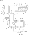
- a motorization device which comprises an internal combustion engine 1, for example of the spark ignition type (operating in particular on gasoline), which is presented here in the form of a four-cylinder engine online. It is an engine 1 which is supercharged by a turbocharger, and which is provided with a low pressure partial recirculation circuit of the exhaust gases (EGR-LP circuit).
- EGR-LP circuit low pressure partial recirculation circuit of the exhaust gases
- the engine 1 is associated with an air intake circuit 2 and an exhaust circuit 3 for the engine's combustion gases. It is also associated with a fuel supply circuit of which the injectors 4 have been shown which supply the different cylinders of the engine with fuel (petrol), for example from a common rail 5.
- fuel for example from a common rail 5.
- the intake circuit 2 comprises, from upstream to downstream in the direction of air circulation from the location marked by the arrow E in the figure: an air filter 6; a flow meter 7 capable of measuring a mass flow rate of air Qair entering the engine; an air intake valve 8, with a first upstream pressure sensor 9 capable of measuring the pressure at the inlet of said valve 8 and a first downstream pressure sensor 10 capable of measuring the pressure at the outlet of said valve 8; a compressor 11 of turbocharger 12; a gas admission valve 13 in the engine, or throttle body 13; an intake gas cooler 14; and, an air distributor 15, or intake manifold 15, provided with a pressure sensor 16 and a temperature sensor 17, which are respectively capable of measuring the value of the pressure Pcol and the value of the temperature Tcol of the gases in the distributor 15.
- the exhaust circuit 3 includes, from upstream to downstream in the direction of circulation of the combustion gases and until their evacuation after post-treatment in the external atmosphere at the location marked by the arrow S in the figure: an exhaust manifold 18; a turbine 19 of the turbocharger 12, mounted on a shaft common to the compressor 11; and a plurality of devices for post-treatment, or depollution, of the combustion gases emitted by the engine 1.
- the turbine 19 serves in a manner known per se to take energy from the exhaust gases (combustion gases) which pass through it by expanding them, and to transfer this energy to the compressor 11 via their common shaft in order to to compress the intake gases.
- the turbine can be of the “variable geometry” type, that is to say include a turbine wheel with vanes of variable inclination, the degree of inclination of which is adjusted to regulate the quantity of energy taken. to the passing gases and the pressure to which the intake gases are compressed (boost pressure).
- the exhaust circuit includes a turbine bypass circuit, equipped with an exhaust discharge valve (well known as a “waste gate” valve according to its name in English). The quantity of energy taken from the exhaust gas is then adjusted by adjusting the flow of exhaust gas passing through the turbine, by opening the discharge valve to a greater or lesser extent.
- the exhaust circuit 3 comprises a first depollution device 20 which is presented here, in the case of a gasoline engine, in the form of a first three-way catalyst 20, for example a close catalyst mounted in the engine compartment of the vehicle, with an upstream oxygen probe 21 of the proportional type capable of measuring a richness value R of the exhaust gases at the inlet of said first catalyst 20, and with furthermore a downstream oxygen probe 22 which can be of the type binary to determine a rich or lean state of the exhaust gases at the outlet of said first catalyst 20, or alternatively, of proportional type to measure a value of the richness of the exhaust gases at the outlet of said first catalyst 20.
- a first depollution device 20 which is presented here, in the case of a gasoline engine, in the form of a first three-way catalyst 20, for example a close catalyst mounted in the engine compartment of the vehicle, with an upstream oxygen probe 21 of the proportional type capable of measuring a richness value R of the exhaust gases at the inlet of said first catalyst 20, and with furthermore a downstream oxygen probe 22 which
- the upstream oxygen sensor 21 alone, or the upstream oxygen sensor 21 associated with the downstream oxygen sensor 22, serves to adjust the proportions of the air - fuel mixture in the engine cylinders for the production of desired engine torque.
- it can be a closed loop adjustment of the richness R of the mixture to a set richness value Rsp equal to 1.
- the signal delivered by the upstream oxygen probe 21 makes it possible to determine the current value of the richness R upstream of the first catalyst 20; the difference between said richness value R and the setpoint Rsp (equal to 1) is entered into a regulator, the output of which is a fuel flow correction value Qcarb,corr which is added to a fuel flow setpoint Qcarb ,sp,bo calculated in open loop from an estimated air flow value in stoichiometric proportions (1 gram of fuel for 14.7 grams of air).
- a regulator the output of which is a fuel flow correction value Qcarb,corr which is added to a fuel flow setpoint Qcarb ,sp,bo calculated in open loop from an estimated air flow value in stoichiometric proportions (1 gram of fuel for 14.7 grams of air).
- it can be a closed loop adjustment of the richness of the mixture R on a set value Rsp which is equal to 1 plus a positive or negative correction value which depends on the indications of the probe at downstream oxygen 22.
- the exhaust circuit 3 includes a second pollution control device 23; here a particle filter 23, and a third pollution control device 24, for example a second three-way catalyst 24 which is mounted under the body of the vehicle.
- the exhaust circuit 3 also includes an exhaust pipe 25 which can be provided with an exhaust valve 26.
- the exhaust circuit 3 comprises a low pressure partial recirculation circuit 27 of the exhaust gases at the intake.
- This EGR-BP circuit 27 takes part of the exhaust gases at a point of the exhaust circuit 3 where they are already expanded by the turbine 19, in the example of the figure downstream of the particle filter 23. It reintroduces these gases at a point of the intake circuit 2 where the intake gases are not further compressed by the compressor 11, on the example of the figure between the air intake valve 8 and the compressor 11.
- the EGR-BP circuit 27 includes a recycled gas cooler 28; a recycled gas filter 29; a recycled gas adjustment valve 30, also called EGR-BP valve 30; and, a device for measuring the differential pressure Pdiff, egrbp prevailing at the terminals of the EGR-BP circuit 27 comprising a differential pressure sensor 32 connected to two upstream 33 and downstream 34 taps of the exhaust circuit, at the ends of the EGR- circuit BP 27.
- the engine can also have other specific features without departing from the scope of the invention.
- it may include a variable intake distribution system (also known as “VVT” according to the English acronym for: Variable Valve Timing), capable of varying the timing of the intake valves in the combustion cycle of the engine. .
- VVT variable intake distribution system
- the method of adjusting the engine 1 is for example consistent with the following description, when the engine is mounted on a motor vehicle:
- An engine torque setpoint C coming from a value of depression of the vehicle's accelerator pedal by the driver, is transformed by a computer (not shown) of the engine, according to the engine speed N, into a setpoint of air flow Qair,sp, a richness setpoint which can be equal to 1 (or alternatively a corrected value), and a recycled gas rate setpoint ⁇ egr,sp, also called EGR rate setpoint.
- the computer calculates a recycled gas flow setpoint Qegrbp,sp, and a total flow setpoint Qmot,sp to be admitted into the engine cylinders, according to the following equations:
- the volumetric efficiency ⁇ is a quantity which depends at least on the engine speed N and the pressure prevailing in the collector Pcol. It may depend on additional parameters such as for example the position of the variable valve timing system on the intake (WT on the intake) if the engine is equipped with it.
- the volumetric efficiency ⁇ is mapped by preliminary tests carried out on an instrumented test bench by varying the different parameters concerned (speed N, pressure in the collector Pcol, etc.), then the map is stored in a memory of the engine computer .
- the total intake gas flow setpoint Qmot,sp is transformed into an intake manifold pressure flow setpoint Pcol,sp (which depends on the temperature Tcol and can vary even if the flow setpoint does not vary).
- the flow rate in the intake manifold Pcol is then adjusted to said pressure setpoint Pcol, sp in a closed loop, by adjusting the angular position of the throttle body 13 when the engine is operating in the atmospheric domain.
- the pressure is regulated by a combination of adjustments of the angular position of the throttle body 13 and the angular position of the blades of the turbine 19 (or alternatively: the position of the “waste gate” valve).
- the current value of the pressure Pcol is determined by the pressure sensor of the intake manifold 16 and the value of the pressure setpoint Pcol, sp is determined using the equation of the filling model, from the mapped volumetric efficiency ⁇ and the temperature value in the intake manifold Tcol which is measured by the temperature sensor 17 of the intake manifold.
- the flow rate of the recycled gases Qegr is adjusted in a closed loop to its setpoint value Qegrbp,sp, which is defined according to the equation mentioned above, generally by adjusting the angular position of the EGR-BP 30 valve. In certain cases, it may be necessary to reduce the opening of the air intake valve 8 so as to create downstream, and therefore at the outlet of the EGR-BP circuit 27, a depression likely to increase the circulation of the recycled gases .
- the current value of the recycled gas flow rate Qegrbp is calculated as the difference between the total intake gas flow rate Qmot (by application of the filling model equation) and the current air flow rate.
- fresh Qair which is determined by the flow meter 7.
- Q HFM The value of the air flow Qair measured by the flow meter 7 is denoted Q HFM in the following (HFM designates the acronym in English for “Hot Flow Meter” which designates a wire flow meter hot).
- the richness R is adjusted in a closed loop around its setpoint Rsp (for example 1) by adjusting the fuel flow, as explained above.
- Rsp for example 1
- a method for diagnosing such a flow meter is known from the state of the art in which, at a stabilized operating point of the engine, the recirculation of the exhaust gases at the intake is eliminated, so that only air is introduced into the engine's combustion chambers.
- the invention aims to remedy the defects of known diagnostic methods, by proposing a reliable diagnostic method, limiting the risks of non-detection and false detection, and not requiring modifying the usual operation of the engine by intrusive adjustments resulting in an increase in fuel consumption or polluting emissions from the engine.
- the engine 1 is here for example of the diesel type, with four cylinders in line, supercharged by turbocharger, equipped with a low pressure partial recirculation circuit 27 of the exhaust gases at the intake, and it also has, in the example shown, a high pressure partial recirculation circuit 37 of the exhaust gases at the intake (also known as: EGR-HP circuit), provided with an adjustment valve 38, called the EGR-HP valve 38.
- a high pressure partial recirculation circuit 37 of the exhaust gases at the intake also known as: EGR-HP circuit
- EGR-HP valve 38 an adjustment valve 38
- This circuit 37 takes part of the exhaust gases at a point of the exhaust circuit 3 located before the turbine 19. Its other end opens downstream of the gas admission valve 13, which is mounted downstream of the compressed gas cooler 14.
- the flow rate of the recycled gases at high pressure is regulated by the degree of opening of the EGR-HP valve 38.
- the intake valve 13 is associated with an upstream pressure sensor 35 and a downstream pressure sensor 36.
- the EGR-HP valve 38 is also associated with an upstream 39 and downstream 40 pressure sensor. The two valves are still each associated with a downstream temperature sensor (not shown on the figure 2 ).
- the pollution control devices 20,23,24, for a diesel engine can be presented as follows:
- the first depollution device 20 is for example an oxidation catalyst. It may also include a nitrogen oxide trap. He is associated with an upstream oxygen probe 21, but it is generally without a downstream oxygen probe.
- the upstream oxygen sensor 21 is generally not used to adjust the richness R of the air-fuel mixture in a closed loop to a set value Rsp when the engine is in a usual mixture operating mode. poor, but for monitoring and diagnostic purposes, Qcarb fuel flow being injected in open loop. In other words, the fuel flow is adjusted in open loop to a flow setpoint value Qcarb,sp,bo which is calculated to correspond to the setpoint torque Csp.
- the probe 21 can be used to adjust said richness R in a closed loop in particular operating modes of the engine such as a mode of regenerating the nitrogen oxide trap in a rich mixture.
- the second depollution device 23 may comprise a catalyst for the selective reduction of nitrogen oxides, also called an SCR catalyst (from the English acronym for: Selective Catalytic Reduction), for example a catalyst also having the function of a particle filter , and an oxidation catalyst.
- SCR catalyst from the English acronym for: Selective Catalytic Reduction
- the third depollution device 24 can be, for example, a second SCR catalyst.
- the engine setting differs from the engine setting shown on the figure 1 in that this example is a diesel engine and there is an additional recirculation circuit, more precisely a high pressure recirculation circuit 37.
- the diesel engine of the figure 2 could have only one low pressure recirculation circuit; in the same way, the gasoline engine of the figure 1 could include a low pressure recirculation circuit and a high pressure recirculation circuit.
- the engine torque setpoint Csp coming from a value of depression of the vehicle's accelerator pedal by the driver, is transformed by a computer (not shown) of the engine, according to the engine speed N, into a setpoint of air flow Qair,sp, a fuel flow setpoint Qcarb,sp,bo which corresponds to a theoretical richness setpoint value Rsp, and an EGR rate setpoint ⁇ egr,sp.
- the computer calculates a recycled gas flow setpoint Qegr,sp and a total flow setpoint Qmot,sp to be admitted into the engine cylinders, according to the following equations:
- the recycled gas flow setpoint Qegr,sp is divided into a gas flow setpoint Qegrhp,sp to be provided by the EGR-HP circuit and a gas flow setpoint Qegrbp,sp to be provided by the circuit EGR-BP, according to specific constraints. For example, to avoid the risk of blocking the EGR-LP valve when cold, it is common to use only high pressure recycled gases.
- the flow rate in the intake manifold Pcol is adjusted to said pressure setpoint Pcol, sp in a closed loop, by adjusting the angular position of the fins of the turbine 19 (or alternatively: the position of the “waste gate” valve), but generally without changing the position of the inlet valve.
- the flow rate of the recycled gases at high pressure Qegrhp is adjusted in a closed loop to its setpoint value Qegrhp,sp, generally by adjusting the angular position of the EGR-HP valve 38.
- the flow rate of the exhaust gases recycled at low pressure Qegrbp is adjusted in a closed loop to its setpoint value Qegrbp, sp generally by adjusting the position of the EGR-BP 30 valve.
- the current flow rate of recycled gases at low pressure Qegrbp is calculated as equal to the value of the total flow rate Qmot (from the filling model), from which the air flow value which is measured by the flow meter Q HFM is subtracted, and from which we further subtract the flow rate of recycled gases at high pressure Qegrhp calculated from the Barré Saint Venant equation.
- the fuel flow Qcarb for a diesel engine, is injected in an open loop to match the target fuel flow Qcarb,sp,bo.
- this target fuel flow Qcarb,sp,bo is calculated as the product of the target air flow Qair,sp multiplied by a theoretical value of target richness to obtain Rsp, which is then divided by 14.7 .
- the upstream oxygen probe 21 is not used to adjust the richness in a closed loop around the theoretical setpoint value Rsp, but to monitor to what extent this setpoint is reached as part of the adjustment of the fuel flow Qcarb in an open loop on its Qcarb,sp,bo deposit.
- FIG. 3 represents the different stages of an embodiment of the diagnostic method according to the invention, which is suitable for a motor with gasoline or a diesel engine provided with at least one EGR-LP circuit and which may also include an EGR-HP circuit.
- the principle of diagnosis according to the invention consists, in the event of a need to diagnose the flow meter 7, which is for example dictated by the on-board diagnostic standards (OBD standards for: On Board Diagnosis), to initially proceed to at least a known pre-diagnosis which is not intrusive, that is to say which does not disturb the operation of the engine and in particular which does not increase its fuel consumption (in the case of a petrol engine) or its polluting emissions (in the case of a diesel engine), and secondly to only carry out the diagnosis of the state of the art in which the recirculation of exhaust gases is cut off at a stabilized operating point only when the pre-diagnosis does not allow us to conclude whether the flow meter is in good condition or faulty.
- OBD on Board Diagnosis
- the method comprises a step 100 which may consist of carrying out one or more subsequent pre-diagnoses of the flow meter.
- These diagnostics are based on the comparison, with two distinct thresholds, of a criterion representative of the difference between a real air flow and the air flow measured by the Q HFM flow meter, said pre-diagnosis not making it possible to conclude when said criterion is between said two thresholds.
- real flow in the sense of this invention is meant a flow value Qair, or a value of a criterion representative of the air flow, which is assumed to be true to the extent that it is measured by means which do not depend on the flow meter and which are assumed to be perfect.
- the criterion is equal to the absolute value of the difference between the air flow measured by the Q HFM flow meter and a Qair flow value calculated from a filling model of the cylinders of the engine and/or Barré Saint Venant models to the valve terminals of the air intake circuit and the engine exhaust circuit.
- this is the absolute value of a fuel flow correction Qcarb,corr applied to adjust in closed loop the value of the richness of the air-fuel mixture R to a set value .
- the current richness value being measured by the upstream oxygen probe 21 of the first depollution device 20 in the context of closed loop regulation, it is a function of the actual air flow, for a given fuel flow. Consequently, a difference between the actual air flow Qair and the air flow measured Q HFM by the flow meter results in a different measurement of the oxygen probe 21, and in a modified correction of the fuel flow Qcarb,corr to be applied as part of closed loop R wealth regulation.
- This embodiment is especially applicable in the case of a gasoline engine, in which such closed-loop adjustment of the richness R is carried out. However, it does not exclude the case of a diesel engine, in which such closed loop adjustment of the richness R is sometimes applied in certain particular circumstances (regeneration of a nitrogen oxide trap in a rich mixture for example) .
- this is the absolute value of the difference between a real richness value R and a theoretical richness setpoint value Rsp corresponding to a fuel flow Qcarb, sp, bo injected in open loop.
- the real richness value R being measured from the indications of the upstream oxygen probe 21, it is a function of the real air flow Qair.
- the target fuel flow Qcarb,sp,bo is calculated from the target air flow Qair,sp which is theoretical and which may not be achieved.
- a first possible pre-diagnosis consists of comparing a first value of the air flow Q HFM measured by the flow meter 7 with a second value of the air flow Qair calculated as the difference between on the one hand, the total flow of gases d the admission Qmot calculated from the filling model, and on the other hand, the sum of the flow rate of the gases recycled at high pressure Qegrhp and the flow rate of the gases recycled at low pressure Qegrbp which are each calculated by Barré Saint Venant models.
- the flow meter is declared in good condition if the absolute value of the difference between the two values is less than a first threshold, and it is declared faulty if the absolute value of the difference is greater than a second threshold which is strictly greater than the first threshold . Due to the imprecision in the different measurements and the different models used in this pre-diagnosis, there is an area between the two thresholds where the pre-diagnosis presents uncertainty and where we cannot conclude.
- a second pre-diagnosis consists of taking advantage of a driving phase where, the driver releasing his foot from the accelerator pedal, the engine torque setpoint Csp becomes zero and the fuel injection is cut off. If there is a need to diagnose the flow meter, the EGR valve(s) present on the engine are closed, which does not create any problem of excess fuel consumption or polluting emissions, as combustion is stopped. The engine then only receives air. A first air flow value measured by the flow meter Q HFM is compared with the total intake flow value Qmot, in fact air, calculated by the filling model.
- the flow meter is declared in good condition if the absolute value of the difference between the two values is less than a third threshold, and it is declared faulty if the absolute value of the difference is greater than a fourth threshold which is strictly greater than the third threshold .
- a third threshold if the absolute value of the difference is less than a third threshold.
- a fourth threshold which is strictly greater than the third threshold.
- a third pre-diagnosis usable in the case of a diesel engine, can be carried out during a regeneration phase of a particle filter, or during a purging phase of a nitrogen oxide trap (so-called “purge” deNOx” in which the trap of nitrogen oxide molecules stored in a lean mixture is emptied, or so-called “deSOx” purge in which the sulfur oxide molecules which have accumulated there are eliminated).
- the flow meter is declared in good condition if the absolute value of the difference between the two values is less than a fifth threshold, and it is declared faulty if the absolute value of the difference is greater than a sixth threshold which is strictly greater than the fifth threshold.
- a fifth threshold if the absolute value of the difference between the two values is less than a fifth threshold
- a sixth threshold which is strictly greater than the fifth threshold.
- a fourth pre-diagnosis consists of monitoring the evolution of the quantity of fuel injected Qcarb for adjusting the richness value R in a closed loop, during a change in the engine torque setpoint.
- the total flow rate of injected fuel Qcarb is the sum of a first flow rate Qcarb,sp,bo calculated as the quantity necessary to achieve the combustion of the fuel with the planned target air flow rate Qair,sp in the engine at the richness of planned setpoint Rsp, and a correction flow rate Qcarb,corr to adjust said richness value R to the setpoint Rsp.
- the first fuel flow calculated thus in open loop Qcarb,sp,bo is equal to the setpoint air flow Qair,sp divided by 14.7.
- the first fuel flow Qcarb,sp,bo constitutes a pre-positioning value for the opening duration of the injectors, which then allows rapid convergence of the closed adjustment loop and with a positive or negative flow correction value which remains low, within known predetermined limits.
- the EGR-LP gas flow is set to a value which is too high, so that the target air flow which was planned Qair,sp does not is not achieved in reality.
- the actual air flow Qair being too low, the upstream oxygen probe 21 indicates richness values R which are also lower, which results in a positive flow correction value Qcarb, fuel corr which goes outside the limits known predetermined.
- the negative fuel flow correction value Qcarb,corr will also be too high (in absolute value) and will exceed the known predetermined limits.
- a fifth pre-diagnosis consists of monitoring the value of the richness R measured by the upstream oxygen probe 21 as part of the open loop adjustment of the fuel flow Qcarb to its setpoint Qcarb,sp,bo.
- the EGR-LP gas flow is set to a value that is too high, so that the air flow of target which was planned Qair,sp is not achieved in reality.
- the upstream oxygen probe 21 indicates a richness value R which is higher than the theoretical setpoint value Rsp which was used to calculate the setpoint fuel flow Qcarb,sp,bo.
- the richness value R is noted.
- the flow meter is declared in good condition if the absolute value of the difference between this value R and the theoretical richness value of reference Rsp corresponding to the quantity of fuel Qcarb, sp, bo injected in an open loop to obtain the target torque Csp is less than a ninth threshold, and it is declared faulty if said absolute value is greater than a tenth threshold which is strictly greater than the ninth threshold. There remains doubt when the absolute value is between said two thresholds.
- test step 200 in which it is checked whether there is any doubt about the failure of the flow meter.
- the method directs towards a step 300 in which the numerator of an IUPR index (English acronym for “In Use Performance Ratio”) is incremented by 1 within the framework of on-board diagnostic standards .
- an alert can be issued. raised to the dashboard of the vehicle in the form of the lighting of a warning light, so that the vehicle can be repaired.
- step 400 the process continues at step 400 in which the recirculation of the exhaust gases is cut off. Then we completely close the EGR-BP 30 valve and also, if necessary, the EGR-HP 38 valve.
- step 500 in which the main diagnosis itself is carried out. It includes, as explained above, a step of measuring a first value of the air flow using the flow meter; a step of calculating a second value of the air flow using the filling model, from the pressure Pcoll and the temperature Tcoll measured in the intake manifold; a step of comparing the absolute value of the difference between said measured value and said calculated value with a threshold; and, a step in which the flow meter is declared in good condition or faulty, respectively depending on whether said absolute value is lower or higher than said threshold.
- the method can also include a step similar to step 300 of incrementing the IUPR index and a step of reporting the fault to the dashboard in the case where the flow meter is non-compliant.
- the method according to the invention makes it possible to limit the occurrences of the very reliable but intrusive main diagnosis, by replacing it with a pre-diagnosis which does not degrade the behavior of the engine in most cases where such a pre-diagnosis does not. presents no doubt about the conclusion.
- the multiplication of pre-diagnoses makes it possible to further reduce these occurrences.
Description
L'invention concerne un procédé de diagnostic de l'état de fonctionnement d'un débitmètre d'air pour un moteur à combustion interne suralimenté, voir par exemple
De nombreux moteurs à combustion interne modernes, en particulier les moteurs diesel et plus récemment les moteurs à essence des véhicules automobiles, sont équipés d'un circuit de recirculation partielle à basse pression des gaz d'échappement à l'admission, dit aussi circuit EGR-BP (EGR étant l'acronyme en anglais pour : « Exhaust Gas Recycling » et BP l'acronyme en français pour : « Basse Pression »).Many modern internal combustion engines, in particular diesel engines and more recently gasoline engines of motor vehicles, are equipped with a low pressure partial recirculation circuit of the exhaust gases at the intake, also known as the EGR circuit. -BP (EGR being the acronym in English for: “Exhaust Gas Recycling” and BP the acronym in French for: “Basse Pressure”).
L'intérêt d'un tel circuit est bien connu, en ce qui concerne les moteurs diesel, pour diminuer les émissions d'oxydes d'azote (NOx) dans les gaz de combustion du moteur, et, en ce qui concerne les moteurs à essence, pour diminuer la consommation de carburant du moteur en le rendant moins sensible au cliquetis et en permettant d'augmenter l'avance à l'allumage du moteur.The benefit of such a circuit is well known, with regard to diesel engines, to reduce emissions of nitrogen oxides (NOx) in the combustion gases of the engine, and, with regard to diesel engines. gasoline, to reduce the fuel consumption of the engine by making it less sensitive to knock and by allowing the ignition advance of the engine to be increased.
Il est important que le débit (massique) des gaz d'échappement recyclés à l'admission soit réglé de manière précise par rapport au débit (massique) d'air admis dans le moteur, de manière à obtenir ladite réduction des émissions de NOx ou de consommation de carburant dans les proportions prévues lors de la mise au point du moteur.It is important that the (mass) flow rate of the exhaust gases recycled to the intake is precisely adjusted in relation to the (mass) flow rate of air admitted into the engine, so as to obtain said reduction in NOx emissions or fuel consumption in the proportions planned during engine development.
Or, un tel réglage se fonde souvent sur la mesure d'une valeur de débit d'air, mesurée par un débitmètre monté à l'entrée du circuit d'admission d'air du moteur, comme on le décrit à l'appui de la
Sur la
Le moteur 1 est associé à un circuit d'admission d'air 2 et à un circuit d'échappement 3 des gaz de combustion du moteur. Il est aussi associé à un circuit d'alimentation en carburant dont on a représenté les injecteurs 4 qui alimentent les différents cylindres du moteur en carburant (essence), par exemple à partir d'une rampe commune 5.The
Le circuit d'admission 2 comprend, d'amont en aval dans le sens de circulation de l'air à partir de l'endroit matérialisé par la flèche E sur la figure : un filtre à air 6 ; un débitmètre 7 apte à mesurer un débit massique d'air Qair pénétrant dans le moteur ; une vanne d'admission d'air 8, avec un premier capteur de pression amont 9 apte à mesurer la pression à l'entrée de ladite vanne 8 et un premier capteur de pression aval 10 apte à mesurer la pression à la sortie de ladite vanne 8 ; un compresseur 11 de turbocompresseur 12 ; une vanne d'admission des gaz 13 dans le moteur, ou boîtier-papillon 13; un refroidisseur 14 des gaz d'admission ; et, un répartiteur d'air 15, ou collecteur d'admission 15, pourvu d'un capteur de pression 16 et d'un capteur de température 17, qui sont respectivement aptes à mesurer la valeur de la pression Pcol et la valeur de la température Tcol des gaz dans le répartiteur 15.The intake circuit 2 comprises, from upstream to downstream in the direction of air circulation from the location marked by the arrow E in the figure: an
Le circuit d'échappement 3 comprend, d'amont en aval dans le sens de circulation des gaz de combustion et jusqu'à leur évacuation après post-traitement dans l'atmosphère extérieure à l'endroit matérialisé par la flèche S sur la figure: un collecteur d'échappement 18 ; une turbine 19 du turbocompresseur 12, montée sur un arbre commun au compresseur 11 ; et une pluralité de dispositifs de post-traitement, ou de dépollution, des gaz de combustion émis par le moteur 1.The
La turbine 19 sert de manière connue en soi à prélever de l'énergie sur les gaz d'échappement (gaz de combustion) qui la traversent en les détendant, et à transférer cette énergie au compresseur 11 par l'intermédiaire de leur arbre commun afin de comprimer les gaz d'admission. Pour cela, la turbine peut être du type « à géométrie variable », c'est-à-dire comprendre une roue de turbine à ailettes d'inclinaison variable, dont on ajuste le degré d'inclinaison pour régler la quantité d'énergie prélevée aux gaz traversants et la pression à laquelle on comprime les gaz d'admission (pression de suralimentation). En variante non représentée, il peut s'agir d'une turbine à géométrie fixe. Dans ce cas, le circuit d'échappement comprend un circuit de contournement de la turbine, muni d'une vanne de décharge à l'échappement (bien connue sous l'appellation de vanne « waste gate » selon sa dénomination en anglais). La quantité d'énergie prélevée aux gaz d'échappement est alors réglée en ajustant le débit de gaz d'échappement traversant la turbine, par une ouverture plus ou moins grande de la vanne de décharge.The
Le circuit d'échappement 3 comporte un premier dispositif de dépollution 20 qui se présente ici, s'agissant d'un moteur à essence, sous la forme d'un premier catalyseur trois voies 20, par exemple un catalyseur rapproché monté dans le compartiment moteur du véhicule, avec une sonde à oxygène amont 21 de type proportionnel apte à mesurer une valeur de richesse R des gaz d'échappement à l'entrée dudit premier catalyseur 20, et avec en outre une sonde à oxygène aval 22 qui peut être de type binaire pour déterminer un état riche ou pauvre des gaz d'échappement à la sortie dudit premier catalyseur 20, ou en variante, de type proportionnel pour mesurer une valeur de la richesse des gaz d'échappement à la sortie dudit premier catalyseur 20. De manière connue en soi, s'agissant dans l'exemple de la
Le circuit d'échappement 3 comporte un deuxième dispositif de dépollution 23; ici un filtre à particules 23, et un troisième dispositif de dépollution 24, par exemple un deuxième catalyseur trois voies 24 qui est monté sous la caisse du véhicule.The
Le circuit d'échappement 3 comprend encore une conduite d'échappement 25 qui peut être munie d'une vanne d'échappement 26.The
En outre, dans le cadre du problème technique traité par l'invention, le circuit d'échappement 3 comprend un circuit de recirculation partielle à basse pression 27 des gaz d'échappement à l'admission. Ce circuit EGR-BP 27 prélève une partie des gaz d'échappement en un point du circuit d'échappement 3 où ils sont déjà détendus par la turbine 19, dans l'exemple de la figure en aval du filtre à particules 23. Il réintroduit ces gaz en un point du circuit d'admission 2 où les gaz d'admission ne sont pas encore comprimés par le compresseur 11, sur l'exemple de la figure entre la vanne d'admission d'air 8 et le compresseur 11.Furthermore, in the context of the technical problem addressed by the invention, the
Le circuit EGR-BP 27 comprend un refroidisseur des gaz recyclés 28 ; un filtre des gaz recyclés 29 ; une vanne de réglage des gaz recyclés 30, dite aussi vanne EGR-BP 30 ; et, un dispositif de mesure de la pression différentielle Pdiff,egrbp régnant aux bornes du circuit EGR-BP 27 comprenant un capteur de pression différentielle 32 relié à deux piquages amont 33 et aval 34 du circuit d'échappement, aux extrémités du circuit EGR-BP 27.The EGR-
Le moteur peut encore présenter d'autres spécificités sans sortir du cadre de l'invention. Par exemple il peut comprendre un système de distribution variable à l'admission (dit aussi « VVT » selon l'acronyme anglais pour : Variable Valve Timing), apte à faire varier le calage des soupapes d'admission dans le cycle de combustion du moteur.The engine can also have other specific features without departing from the scope of the invention. For example, it may include a variable intake distribution system (also known as “VVT” according to the English acronym for: Variable Valve Timing), capable of varying the timing of the intake valves in the combustion cycle of the engine. .
Le procédé de réglage du moteur 1 est par exemple conforme à la description suivante, quand le moteur est monté sur un véhicule automobile :
Une consigne de couple C moteur, provenant d'une valeur d'enfoncement de la pédale d'accélérateur du véhicule par le conducteur, est transformée par un calculateur (non représenté) du moteur, selon le régime N du moteur, en une consigne de débit d'air Qair,sp , une consigne de richesse qui peut être égale à 1 (ou en variante une valeur corrigée), et en une consigne de taux de gaz recyclés τegr,sp , dite aussi consigne de taux d'EGR. A partir de ces valeurs, le calculateur calcule une consigne de débit des gaz recyclés Qegrbp,sp , et une consigne de débit total Qmot,sp à admettre dans les cylindres du moteur, selon les équations suivantes : ![]()
![]()
An engine torque setpoint C, coming from a value of depression of the vehicle's accelerator pedal by the driver, is transformed by a computer (not shown) of the engine, according to the engine speed N, into a setpoint of air flow Qair,sp, a richness setpoint which can be equal to 1 (or alternatively a corrected value), and a recycled gas rate setpoint τegr,sp, also called EGR rate setpoint. From these values, the computer calculates a recycled gas flow setpoint Qegrbp,sp, and a total flow setpoint Qmot,sp to be admitted into the engine cylinders, according to the following equations:![]()
![]()
On règle ensuite, d'une part, le débit total des gaz d'admission entrant dans le moteur, et d'autre part, le débit des gaz recyclés, dit aussi débit d'EGR. Le débit d'air n'est pas réglé directement, mais il est la résultante de ces deux réglages. On détaille maintenant la manière de procéder à ces deux réglages.We then adjust, on the one hand, the total flow rate of the intake gases entering the engine, and on the other hand, the flow rate of the recycled gases, also known as the EGR flow rate. The air flow is not adjusted directly, but is the result of these two settings. We now detail how to make these two settings.
Pour régler le débit total des gaz d'admission admis dans le moteur, on se sert d'une correspondance entre la valeur du débit Qmot et la valeur de la pression Pcol régnant dans le collecteur d'admission 15, plus précisément, d'un modèle de remplissage selon l'équation suivante : ![]()
- Qmot désigne le débit entrant dans le moteur (exprimé en kg/s),
- COEFF est un coefficient constant qui dépend du nombre de cylindres dans le moteur et du nombre de temps (par exemple ½ pour un moteur à 4 cylindres et 4 temps)
- N désigne le régime du moteur (en tour/min)
- CYL désigne la cylindrée du moteur (en m3))
- Pcol désigne la pression dans le collecteur d'admission (en bars)
- r est la constante des gaz parfaits pour l'air, soit 287,058 J*kg-1*K-1
- Pcol désigne la pression dans le collecteur d'admission (en Pa)
- Tcol désigne la température dans le collecteur d'admission (en K)
- η (coefficient sans unité) désigne le rendement volumétrique ; il s'agit du rapport entre le volume d'air entrant réellement dans les cylindres, divisé par le volume qui pourrait théoriquement y entrer compte tenu du volume des chambres de combustion du moteur.
- Qmot designates the flow entering the engine (expressed in kg/s),
- COEFF is a constant coefficient which depends on the number of cylinders in the engine and the number of strokes (for example ½ for a 4-cylinder, 4-stroke engine)
- N designates the engine speed (in rpm)
- CYL designates the engine displacement (in m 3 ))
- Pcol designates the pressure in the intake manifold (in bars)
- r is the ideal gas constant for air, i.e. 287.058 J*kg -1 *K -1
- Pcol designates the pressure in the intake manifold (in Pa)
- Tcol designates the temperature in the intake manifold (in K)
- η (unitless coefficient) designates the volumetric efficiency; this is the ratio of the volume of air actually entering the cylinders, divided by the volume that could theoretically enter given the volume of the engine's combustion chambers.
Le rendement volumétrique η est une grandeur qui dépend au moins du régime N du moteur et de la pression régnant dans le collecteur Pcol. Il peut dépendre de paramètres supplémentaires comme par exemple la position du système de distribution variable à l'admission (WT à l'admission) si le moteur en est équipé. Le rendement volumétrique η est cartographié par des essais préalables réalisés sur banc d'essai instrumenté an faisant varier les différents paramètres concernés (régime N, pression dans le collecteur Pcol, etc.), puis la cartographie est stockée dans une mémoire du calculateur du moteur.The volumetric efficiency η is a quantity which depends at least on the engine speed N and the pressure prevailing in the collector Pcol. It may depend on additional parameters such as for example the position of the variable valve timing system on the intake (WT on the intake) if the engine is equipped with it. The volumetric efficiency η is mapped by preliminary tests carried out on an instrumented test bench by varying the different parameters concerned (speed N, pressure in the collector Pcol, etc.), then the map is stored in a memory of the engine computer .
En fonctionnement embarqué sur le véhicule, la consigne de débit total des gaz d'admission Qmot,sp est transformée en une consigne de débit de pression de collecteur d'admission Pcol,sp (qui dépend de la température Tcol et peut varier même si la consigne de débit ne varie pas).On règle alors le débit dans le collecteur d'admission Pcol sur ladite consigne de pression Pcol,sp en boucle fermée, en ajustant la position angulaire du boîtier-papillon 13 quand le moteur fonctionne dans le domaine atmosphérique. Dans le domaine suralimenté, la pression est réglée par une combinaison des ajustements de position angulaire du boîtier-papillon 13 et de position angulaire des ailettes de la turbine 19 (ou en variante : de position de la vanne « waste gâte »). A chaque instant, la valeur courante de la pression Pcol est déterminée par le capteur de pression du collecteur d'admission 16 et la valeur de la consigne de pression Pcol,sp est déterminée grâce à l'équation du modèle de remplissage, à partir du rendement volumétrique η cartographié et de la valeur de température dans le collecteur d'admission Tcol qui est mesurée par le capteur de température 17 du collecteur d'admission.In on-board operation on the vehicle, the total intake gas flow setpoint Qmot,sp is transformed into an intake manifold pressure flow setpoint Pcol,sp (which depends on the temperature Tcol and can vary even if the flow setpoint does not vary). The flow rate in the intake manifold Pcol is then adjusted to said pressure setpoint Pcol, sp in a closed loop, by adjusting the angular position of the
Le débit des gaz recyclés Qegr est réglé en boucle fermée sur sa valeur de consigne Qegrbp,sp , qui est définie selon l'équation mentionnée plus haut, généralement en ajustant la position angulaire de la vanne EGR-BP 30. Dans certains cas, il peut être nécessaire de de diminuer l'ouverture de la vanne d'admission d'air 8 de manière à créer à son aval, et donc à la sortie du circuit EGR-BP 27, une dépression de nature à augmenter la circulation des gaz recyclés.The flow rate of the recycled gases Qegr is adjusted in a closed loop to its setpoint value Qegrbp,sp, which is defined according to the equation mentioned above, generally by adjusting the angular position of the EGR-
Dans le cadre de cette régulation, la valeur courante du débit de gaz recyclés Qegrbp est calculée comme la différence entre le débit total des gaz d'admission Qmot (par application de l'équation du modèle de remplissage) et du débit courant d'air frais Qair qui est déterminé par le débitmètre 7. La valeur du débit d'air Qair mesurée par le débitmètre 7 est notée QHFM dans la suite (HFM désigne l'acronyme en anglais pour « Hot Flow Meter » qui désigne un débitmètre à fil chaud).As part of this regulation, the current value of the recycled gas flow rate Qegrbp is calculated as the difference between the total intake gas flow rate Qmot (by application of the filling model equation) and the current air flow rate. fresh Qair which is determined by the
La richesse R est réglée en boucle fermée autour de sa consigne Rsp (par exemple 1) en ajustant le débit de carburant, comme exposé plus haut. On comprend de ce qui précède que la précision de la mesure par le débitmètre QHFM du débit d'air Qair est très importante pour le réglage du débit adéquat de gaz recyclés Qegrbp.The richness R is adjusted in a closed loop around its setpoint Rsp (for example 1) by adjusting the fuel flow, as explained above. We understand from the above that the precision of the measurement by the Q HFM flow meter of the air flow Qair is very important for adjusting the adequate flow rate of recycled gases Qegrbp.
Sur un moteur à essence, une surestimation du débit d'air par le débitmètre entraîne une sous-estimation du débit de gaz recyclés qui est réellement obtenu. Cela peut se traduire, quand le taux d'EGR devient trop élevé, à des ratés de combustion et/ou à des instabilités qui augmentent les émissions polluantes du moteur, et à une mauvaise maîtrise du couple qui peut entraîner des problèmes d'agrément, notamment lors de changements de rapport de boîte de vitesses automatique.On a gasoline engine, an overestimation of the air flow by the flow meter leads to an underestimation of the recycled gas flow which is actually obtained. This can result, when the EGR rate becomes too high, in combustion misfires and/or instabilities which increase the polluting emissions of the engine, and in poor torque control which can lead to approval problems, particularly when changing automatic gearbox ratios.
Dans le cas d'un moteur diesel (décrit plus loin à l'appui de la
Il existe donc un besoin de vérifier le bon fonctionnement d'un débitmètre utilisé dans un tel procédé de réglage d'un débit de gaz d'échappement recyclés à basse pression. On connaît de l'état de l'art un procédé de diagnostic d'un tel débitmètre dans lequel, sur un point de fonctionnement stabilisé du moteur, on supprime la recirculation des gaz d'échappement à l'admission, de sorte que seul de l'air est introduit dans les chambres de combustion du moteur. On compare alors la valeur du débit d'air mesurée par le débitmètre QHFM avec une valeur Q(Pcol,Tcol) calculée grâce à l'équation du modèle de remplissage (à partir d'une mesure de pression Pcol et de température Tcol dans le collecteur d'admission), les deux valeurs étant stabilisées, et on constate une défaillance du débitmètre si l'écart entre les deux mesures est supérieur à un seuil pré-calibré. Ce procédé a fait la preuve de sa précision, et il est utilisé en grande série.There is therefore a need to verify the proper functioning of a flow meter used in such a process for adjusting a flow rate of recycled exhaust gases at low pressure. A method for diagnosing such a flow meter is known from the state of the art in which, at a stabilized operating point of the engine, the recirculation of the exhaust gases at the intake is eliminated, so that only air is introduced into the engine's combustion chambers. We then compare the value of the air flow measured by the flow meter Q HFM with a value Q(Pcol, Tcol) calculated using the equation of the filling model (from a measurement of pressure Pcol and temperature Tcol in the intake manifold), the two values being stabilized, and a failure of the flow meter is noted if the difference between the two measurements is greater than a pre-calibrated threshold. This process has proven its precision, and it is used in large series.
Cependant il est intrusif, car il nécessite de dérégler le moteur par rapport à son fonctionnement normal, et la coupure de la recirculation des gaz d'échappement crée, dans le cas d'un moteur à essence, une plus grande sensibilité au cliquetis qui nécessite de procéder à des retraits d'avance, ce qui augmente la consommation de carburant si le couple reste identique, ou ce qui crée, dans le cas d'un moteur diesel, un pic d'émissions polluantes (oxydes d'azote ou suies), ce qui représente un risque pour le respect des normes légales régissant les émissions polluantes des véhicules automobiles.However, it is intrusive, because it requires deregulating the engine from its normal operation, and cutting off the recirculation of exhaust gases creates, in the case of a gasoline engine, greater sensitivity to knock which requires to make withdrawals in advance, which increases fuel consumption if the torque remains the same, or which creates, in the case of a diesel engine, a peak in polluting emissions (nitrogen oxides or soot) , which represents a risk for compliance with legal standards governing polluting emissions from motor vehicles.
L'invention vise à remédier aux défauts des procédés de diagnostic connus, en proposant un procédé de diagnostic fiable, limitant les risques de non-détection et de fausse détection, et ne nécessitant pas de modifier le fonctionnement habituel du moteur par des réglages intrusifs entraînant une augmentation de la consommation de carburant ou des émissions polluantes du moteur.The invention aims to remedy the defects of known diagnostic methods, by proposing a reliable diagnostic method, limiting the risks of non-detection and false detection, and not requiring modifying the usual operation of the engine by intrusive adjustments resulting in an increase in fuel consumption or polluting emissions from the engine.
Pour atteindre cet objectif, l'invention porte sur un procédé de diagnostic d'un débitmètre d'air dans un moteur à combustion interne suralimenté, comportant au moins un circuit de recirculation partielle à basse pression des gaz d'échappement à l'admission du moteur, et pouvant comporter en outre un circuit de recirculation partielle à haute pression des gaz d'échappement à l'admission du moteur, ledit procédé comprenant au moins une étape de coupure du recyclage des gaz d'échappement puis une étape de diagnostic principal dans laquelle : on mesure une première valeur du débit d'air admis dans le moteur par le débitmètre ; on calcule une deuxième valeur du débit d'air grâce à un modèle de remplissage des cylindres du moteur ; et, on conclut que le débitmètre est en bon état ou défaillant respectivement quand la valeur absolue de l'écart entre ladite première et ladite deuxième valeur est inférieure ou supérieure à un seuil. La principale caractéristique du procédé selon l'invention est que :
- Il comporte, préalablement à la coupure du recyclage des gaz d'échappement, une étape dans laquelle on réalise au moins un pré-diagnostic du débitmètre, dans lequel on compare un critère représentatif de l'écart entre le débit d'air réel et le débit d'air mesuré par le débitmètre avec deux seuils, le pré-diagnostic permettant de conclure que le débitmètre est en bon état lorsque ledit écart est inférieur au plus petit des deux seuils et qu'il est défaillant lorsque ledit écart est supérieur au plus grand des deux seuils, ledit pré-diagnostic ne permettant pas de conclure lorsque ledit écart est compris entre les deux seuils ; et,
- l'étape de coupure de la recirculation des gaz d'échappement et l'étape de diagnostic principal ne sont mises en oeuvre que lorsque ledit pré-diagnostic ne permet pas de conclure.
- It comprises, prior to cutting off the exhaust gas recycling, a step in which at least one pre-diagnosis of the flow meter is carried out, in which a criterion representative of the difference between the actual air flow and the air flow measured by the flow meter with two thresholds, the pre-diagnosis making it possible to conclude that the flow meter is in good condition when said deviation is less than the smallest of the two thresholds and that it is faulty when said deviation is greater than the most large of the two thresholds, said pre-diagnosis not making it possible to conclude when said difference is between the two thresholds; And,
- the step of cutting off the exhaust gas recirculation and the main diagnosis step are only implemented when said pre-diagnosis does not allow a conclusion to be reached.
L'invention sera mieux comprise à la lecture d'un mode de réalisation non limitatif de celle-ci, à l'appui des figures annexées parmi lesquelles :
- [
Fig. 1 ] Lafigure 1 est une représentation schématique d'un premier exemple de dispositif de motorisation apte à la mise en oeuvre du procédé selon l'invention. - [
Fig. 2 ] Lafigure 2 est une représentation graphique d'un deuxième exemple de dispositif de motorisation apte à la mise en oeuvre du procédé selon l'invention. - [
Fig. 3 ] Lafigure 3 est un logigramme qui représente les différentes étapes du procédé selon l'invention, selon un mode de réalisation.
- [
Fig. 1 ] Therefigure 1 is a schematic representation of a first example of a motorization device suitable for implementing the method according to the invention. - [
Fig. 2 ] Therefigure 2 is a graphic representation of a second example of a motorization device suitable for implementing the method according to the invention. - [
Fig. 3 ] ThereFigure 3 is a flowchart which represents the different stages of the process according to the invention, according to one embodiment.
La
Sur la
Le moteur 1 est ici par exemple du type diesel, à quatre cylindres en ligne, suralimenté par turbocompresseur, équipé d'un circuit de recirculation partielle à basse pression 27 des gaz d'échappement à l'admission, et il présente en outre, dans l'exemple représenté, un circuit de recirculation partielle à haute pression 37 des gaz d'échappement à l'admission (dit aussi : circuit EGR-HP), muni d'une vanne de réglage 38, dite vanne EGR-HP 38.The
Ce circuit 37 prélève une partie des gaz d'échappement en un point du circuit d'échappement 3 situé avant la turbine 19. Son autre extrémité débouche en aval de la vanne d'admission des gaz 13, qui est quant à elle montée en aval du refroidisseur des gaz comprimés 14. Le débit des gaz recyclés à haute pression est réglé par le degré d'ouverture de la vanne EGR-HP 38. Dans le cas d'un moteur diesel, il est aussi connu de fermer partiellement la vanne d'admission 13 pour aspirer davantage de gaz d'échappement recyclés provenant du circuit EGR-HP 37, lorsque la dépression entre les extrémités du circuit 37 est trop faible pour assurer un débit suffisant.This
La vanne d'admission 13 est associée à un capteur de pression amont 35 et à un capteur de pression aval 36. La vanne EGR-HP 38 est aussi associée à un capteur de pression amont 39 et aval 40. Les deux vannes sont encore chacune associées à un capteur de température aval (non représentés sur la
Les dispositifs de dépollution 20,23,24, pour un moteur diesel, peuvent se présenter de la façon suivante :
Le premier dispositif de dépollution 20 est par exemple un catalyseur d'oxydation. Il peut comprendre aussi un piège à oxydes d'azote. Il est associé à une sonde à oxygène amont 21, mais il est généralement dépourvu de sonde à oxygène aval. Dans le cas d'un moteur diesel, la sonde à oxygène amont 21 ne sert généralement pas à régler la richesse R du mélange air- carburant en boucle fermée sur une valeur de consigne Rsp lorsque le moteur est dans un mode de fonctionnement habituel en mélange pauvre, mais à des fins de surveillance et de diagnostic, le débit de carburant Qcarb étant injecté en boucle ouverte. En d'autres termes, le débit de carburant est réglé en boucle ouverte sur une valeur de consigne de débit Qcarb,sp,bo qui est calculée pour correspondre au couple de consigne Csp. Cependant, la sonde 21 peut servir à régler ladite richesse R en boucle fermée dans des modes de fonctionnement particuliers du moteur tels qu'un mode de régénération du piège à oxydes d'azote en mélange riche.The
The
Le deuxième dispositif de dépollution 23 peut comprendre un catalyseur de réduction sélective des oxydes d'azote, dit aussi catalyseur SCR (de l'acronyme anglais pour : Sélective Catalytic Réduction), par exemple un catalyseur ayant aussi la fonction d'un filtre à particules, et un catalyseur d'oxydation.The
Le troisième dispositif de dépollution 24 peut être, par exemple, un deuxième catalyseur SCR.The
La nature et le fonctionnement des différents dispositifs de dépollution sont bien connus en soi et ne seront pas davantage détaillés.The nature and operation of the various depollution devices are well known in themselves and will not be detailed further.
Le réglage du moteur diffère du réglage du moteur présenté sur la
Cependant on notera qu'il s'agit d'un exemple non limitatif. En variante, le moteur diesel de la
La consigne de couple Csp moteur, provenant d'une valeur d'enfoncement de la pédale d'accélérateur du véhicule par le conducteur, est transformée par un calculateur (non représenté) du moteur, selon le régime N du moteur, en une consigne de débit d'air Qair,sp , une consigne de débit de carburant Qcarb,sp,bo qui correspond à une valeur théorique de consigne de richesse Rsp, et une consigne de taux d'EGR τegr,sp . A partir de ces valeurs, le calculateur calcule une consigne de débit des gaz recyclés Qegr,sp et une consigne de débit total Qmot,sp à admettre dans les cylindres du moteur, selon les équations suivantes : ![]()
![]()
![]()
![]()
D'autre part, la consigne de débit des gaz recyclés Qegr,sp est répartie en une consigne de débit des gaz Qegrhp,sp à fournir par le circuit EGR-HP et une consigne de débit des gaz Qegrbp,sp à fournir par le circuit EGR-BP, selon des contraintes spécifiques. Par exemple, pour éviter des risques de blocage de la vanne EGR-BP à froid, il est courant de n'utiliser que des gaz recyclés à haute pression.On the other hand, the recycled gas flow setpoint Qegr,sp is divided into a gas flow setpoint Qegrhp,sp to be provided by the EGR-HP circuit and a gas flow setpoint Qegrbp,sp to be provided by the circuit EGR-BP, according to specific constraints. For example, to avoid the risk of blocking the EGR-LP valve when cold, it is common to use only high pressure recycled gases.
On règle ensuite, d'une part, le débit total des gaz d'admission entrant dans le moteur, et d'autre part, le débit des gaz recyclés à haute pression, et le débit des gaz recyclés à basse pression. Le débit d'air n'est pas réglé directement, mais il est la résultante de ces deux réglages.We then adjust, on the one hand, the total flow rate of the intake gases entering the engine, and on the other hand, the flow rate of the gases recycled at high pressure, and the flow rate of the gases recycled at low pressure. The air flow is not adjusted directly, but is the result of these two settings.
Pour régler le débit total des gaz d'admission admis dans le moteur, on procède comme dans l'exemple de la
Le débit des gaz recyclés à haute pression Qegrhp est réglé en boucle fermée sur sa valeur de consigne Qegrhp,sp , généralement en ajustant la position angulaire de la vanne EGR-HP 38. La valeur courante du débit des gaz recyclés à haute pression Qegrhp est déterminé à partir d'un modèle de Barré Saint Venant aux bornes de la vanne EGR-HP 38, conformément à l'équation suivante : ![]()
![]()
Le débit des gaz d'échappement recyclés à basse pression Qegrbp est réglé en boucle fermé sur sa valeur de consigne Qegrbp,sp généralement en ajustant la position de la vanne EGR-BP 30. Dans ce cas où un circuit EGR-HP est présent, le débit courant de gaz recyclés à basse pression Qegrbp est calculé comme égal à la valeur du débit total Qmot (issu du modèle de remplissage), auquel on retranche la valeur de débit d'air qui est mesurée par le débitmètre QHFM, et auquel on retranche en outre le débit de gaz recyclés à haute pression Qegrhp calculé à partir de l'équation de Barré Saint Venant.The flow rate of the exhaust gases recycled at low pressure Qegrbp is adjusted in a closed loop to its setpoint value Qegrbp, sp generally by adjusting the position of the EGR-
Le débit de carburant Qcarb, s'agissant d'un moteur diesel, est injecté en boucle ouverte pour correspondre au débit de carburant de consigne Qcarb,sp,bo. Par exemple, ce débit de carburant de consigne Qcarb,sp,bo est calculé comme le produit du débit d'air de consigne Qair,sp multiplié par une valeur théorique de richesse de consigne à obtenir Rsp, qui est ensuite divisé par 14,7. Ici, la sonde à oxygène amont 21 ne sert pas à régler la richesse en boucle fermée autour de la valeur théorique de consigne Rsp, mais à surveiller dans quelle mesure cette consigne est atteinte dans le cadre du réglage du débit de carburant Qcarb en boucle ouverte sur sa consigne Qcarb,sp,bo.The fuel flow Qcarb, for a diesel engine, is injected in an open loop to match the target fuel flow Qcarb,sp,bo. For example, this target fuel flow Qcarb,sp,bo is calculated as the product of the target air flow Qair,sp multiplied by a theoretical value of target richness to obtain Rsp, which is then divided by 14.7 . Here, the
La
Le principe du diagnostic selon l'invention consiste, en cas de besoin de diagnostiquer le débitmètre 7, qui est par exemple dicté par les normes de diagnostic embarqué (normes OBD pour : On Board Diagnosis), à procéder dans un premier temps à au moins un pré-diagnostic connu qui ne soit pas intrusif, c'est-à-dire qui ne perturbe pas le fonctionnement du moteur et notamment qui n'augmente pas sa consommation de carburant (dans le cas d'un moteur à essence) ou ses émissions polluantes (dans le cas d'un moteur diesel), et dans un deuxième temps à ne procéder au diagnostic de l'état de l'art dans lequel on coupe la recirculation des gaz d'échappement sur un point de fonctionnement stabilisé que lorsque le pré-diagnostic ne permet pas de conclure si le débitmètre est en bon état ou défaillant.The principle of diagnosis according to the invention consists, in the event of a need to diagnose the
Le procédé comprend une étape 100 qui peut consister à réaliser un ou plusieurs pré-diagnostics suivants du débitmètre.The method comprises a
Ces diagnostics sont basés sur la comparaison, avec deux seuils distincts, d'un critère représentatif de l'écart entre un débit d'air réel et le débit d'air mesuré par le débitmètre QHFM, ledit pré-diagnostic ne permettant pas de conclure lorsque ledit critère est compris entre lesdits deux seuils.These diagnostics are based on the comparison, with two distinct thresholds, of a criterion representative of the difference between a real air flow and the air flow measured by the Q HFM flow meter, said pre-diagnosis not making it possible to conclude when said criterion is between said two thresholds.
Par l'expression « débit réel », on entend au sens de cette invention une valeur de débit Qair, ou une valeur d'un critère représentatif du débit d'air, qui est supposée vraie dans la mesure où elle est mesurée par des moyens qui ne dépendent pas du débitmètre et qui sont quant à eux supposés parfaits.By the expression "real flow", in the sense of this invention is meant a flow value Qair, or a value of a criterion representative of the air flow, which is assumed to be true to the extent that it is measured by means which do not depend on the flow meter and which are assumed to be perfect.
Selon plusieurs modes de réalisation du pré-diagnostic, le critère est égal à la valeur absolue de l'écart entre le débit d'air mesuré par le débitmètre QHFM et une valeur de débit Qair calculée à partir d'un modèle de remplissage des cylindres du moteur et/ou de modèles de Barré Saint Venant aux bornes de vannes du circuit d'admission d'air et du circuit d'échappement du moteur.According to several embodiments of the pre-diagnosis, the criterion is equal to the absolute value of the difference between the air flow measured by the Q HFM flow meter and a Qair flow value calculated from a filling model of the cylinders of the engine and/or Barré Saint Venant models to the valve terminals of the air intake circuit and the engine exhaust circuit.
Dans un mode de réalisation en variante, il s'agit de la valeur absolue de d'une correction de débit de carburant Qcarb,corr appliquée pour régler en boucle fermée la valeur de la richesse du mélange air-carburant R sur une valeur de consigne. La valeur de richesse courante étant mesurée par la sonde à oxygène amont 21 du premier dispositif de dépollution 20 dans le cadre de la régulation en boucle fermée, elle est une fonction du débit d'air réel, pour un débit de carburant donné. Par conséquent, un écart entre le débit d'air réel Qair et le débit d'air mesuré QHFM par le débitmètre se traduit par une mesure différente de la sonde à oxygène 21, et par une correction modifiée du débit de carburant Qcarb,corr à appliquer dans le cadre de la régulation de richesse R en boucle fermée. Ce mode de réalisation est surtout applicable dans le cas d'un moteur à essence, dans lequel un tel réglage de la richesse R en boucle fermée est réalisé. Cependant il n'exclut pas le cas d'un moteur diesel, dans lequel un tel réglage en boucle fermé de la richesse R est parfois appliqué dans certaines circonstances particulières (régénération d'un piège à oxydes d'azote en mélange riche par exemple).In a variant embodiment, this is the absolute value of a fuel flow correction Qcarb,corr applied to adjust in closed loop the value of the richness of the air-fuel mixture R to a set value . The current richness value being measured by the
Dans encore un autre mode de réalisation en variante, il s'agit de la valeur absolue de la différence entre une valeur réelle de richesse R et une valeur théorique de consigne de richesse Rsp correspondant à un débit de carburant Qcarb,sp,bo injecté en boucle ouverte. La valeur réelle de richesse R étant mesurée à partir des indications de la sonde à oxygène amont 21, elle est une fonction du débit d'air réel Qair. En revanche, le débit de carburant de consigne Qcarb,sp,bo est calculé à partir du débit d'air de consigne Qair,sp qui est théorique est qui peut ne pas être atteint. Par conséquent, un écart entre le débit d'air réel Qair et le débit mesuré QHFM par le débitmètre conduit, pour une même quantité de carburant Qcarb,sp,bo injectée en boucle ouverte, à un écart entre la valeur de richesse R mesurée par la sonde amont 21 et la valeur théorique de consigne Rsp qui sert au calcul du débit de carburant de consigne Qcarb,sp,bo en boucle ouverte. Ce mode de réalisation concerne surtout les moteurs diesel. Cependant il n'exclut pas le cas d'un moteur à essence dans lequel le carburant viendrait à être injecté en boucle ouverte (par exemple : sur certains points de fonctionnement en pleine charge du moteur, où la richesse est strictement supérieure à 1).In yet another alternative embodiment, this is the absolute value of the difference between a real richness value R and a theoretical richness setpoint value Rsp corresponding to a fuel flow Qcarb, sp, bo injected in open loop. The real richness value R being measured from the indications of the
Un premier pré-diagnostic possible consiste à comparer une première valeur du débit d'air QHFM mesuré par le débitmètre 7 avec une seconde valeur du débit d'air Qair calculée comme la différence entre d'une part, le débit total des gaz d'admission Qmot calculé à partir du modèle de remplissage, et d'autre part, la somme du débit des gaz recyclés à haute pression Qegrhp et du débit des gaz recyclés à basse pression Qegrbp qui sont chacun calculés par des modèles de Barré Saint Venant. Le débitmètre est déclaré en bon état si la valeur absolue de la différence entre les deux valeurs est inférieure à un premier seuil, et il est déclaré défaillant si la valeur absolue de la différence est supérieure à un deuxième seuil qui est strictement supérieur au premier seuil. En raison de l'imprécision sur les différentes mesures et les différents modèles utilisés dans ce pré-diagnostic, il existe une zone entre les deux seuils où le pré-diagnostic présente une incertitude et où on ne peut pas conclure.A first possible pre-diagnosis consists of comparing a first value of the air flow Q HFM measured by the
Un deuxième pré-diagnostic consiste à profiter d'une phase de roulage où, le conducteur relâchant le pied de la pédale d'accélérateur, la consigne de couple moteur Csp devient nulle et on coupe l'injection de carburant. En présence d'un besoin de diagnostiquer le débitmètre, on ferme la ou les vannes EGR présentes sur le moteur, ce qui ne crée aucun problème de surconsommation de carburant ni d'émissions polluantes, la combustion étant stoppée. Le moteur ne reçoit alors que de l'air. On compare une première valeur de débit d'air mesurée par le débitmètre QHFM avec la valeur de débit total d'admission Qmot, en fait de l'air, calculée par le modèle de remplissage. Le débitmètre est déclaré en bon état si la valeur absolue de la différence entre les deux valeurs est inférieure à un troisième seuil, et il est déclaré défaillant si la valeur absolue de la différence est supérieure à un quatrième seuil qui est strictement supérieur au troisième seuil. Ici aussi, il existe une zone entre les deux seuils où le pré-diagnostic présente une incertitude, en raison des phénomènes transitoires lors de la phase de lever de pied.A second pre-diagnosis consists of taking advantage of a driving phase where, the driver releasing his foot from the accelerator pedal, the engine torque setpoint Csp becomes zero and the fuel injection is cut off. If there is a need to diagnose the flow meter, the EGR valve(s) present on the engine are closed, which does not create any problem of excess fuel consumption or polluting emissions, as combustion is stopped. The engine then only receives air. A first air flow value measured by the flow meter Q HFM is compared with the total intake flow value Qmot, in fact air, calculated by the filling model. The flow meter is declared in good condition if the absolute value of the difference between the two values is less than a third threshold, and it is declared faulty if the absolute value of the difference is greater than a fourth threshold which is strictly greater than the third threshold . Here too, there is a zone between the two thresholds where the pre-diagnosis presents an uncertainty, due to transient phenomena during the lifting phase.
Un troisième pré-diagnostic, utilisable dans le cas d'un moteur diesel, est réalisable pendant une phase de régénération d'un filtre à particules, ou pendant une phase de purge d'un piège à oxydes d'azote (purge dite de « déNOx » dans laquelle on vide le piège des molécules d'oxydes d'azote stockées en mélange pauvre, ou purge dite de « déSOx » dans laquelle on élimine les molécules d'oxydes de soufre qui s'y sont accumulées).A third pre-diagnosis, usable in the case of a diesel engine, can be carried out during a regeneration phase of a particle filter, or during a purging phase of a nitrogen oxide trap (so-called “purge” deNOx” in which the trap of nitrogen oxide molecules stored in a lean mixture is emptied, or so-called “deSOx” purge in which the sulfur oxide molecules which have accumulated there are eliminated).
Ces modes nécessitent un fort enrichissement du mélange air-carburant. Pour cela on procède notamment à une fermeture partielle de la vanne d'admission, ce qui a pour effet de diminuer le débit d'air Qair tout en augmentant le débit Qegrhp des gaz EGR-HP aspirés. En parallèle, le circuit EGR-BP est coupé, c'est-à-dire que la vanne EGR-BP 30 est complètement fermée. La vanne d'admission des gaz 13, qui est située en amont du point d'arrivée des gaz EGR-HP, n'est traversée que par de l'air. A l'occasion de cette régénération ou de cette purge, on compare la première valeur du débit d'air mesurée par le débitmètre QHFM avec une deuxième valeur du débit d'air Qair déterminée par un modèle de Barré Saint Venant aux bornes de la vanne d'admission 13. Le débitmètre est déclaré en bon état si la valeur absolue de la différence entre les deux valeurs est inférieure à un cinquième seuil, et il est déclaré défaillant si la valeur absolue de la différence est supérieure à un sixième seuil qui est strictement supérieur au cinquième seuil. Ici aussi, il existe une zone entre les deux seuils où le pré-diagnostic présente une incertitude et ne permet pas de conclure.These modes require strong enrichment of the air-fuel mixture. To do this, we carry out in particular a partial closure of the intake valve, which has the effect of reducing the air flow Qair while increasing the flow Qegrhp of the EGR-HP gases sucked in. At the same time, the EGR-BP circuit is cut, that is to say the EGR-
Un quatrième pré-diagnostic consiste à suivre l'évolution de la quantité de carburant injectée Qcarb pour le réglage de la valeur de richesse R en boucle fermée, lors d'un changement de consigne de couple du moteur. Le débit total de carburant injecté Qcarb est la somme d'un premier débit Qcarb,sp,bo calculé comme la quantité nécessaire pour réaliser la combustion du carburant avec le débit d'air de consigne prévu Qair,sp dans le moteur à la richesse de consigne prévue Rsp, et d'une correction de débit Qcarb,corr pour régler ladite valeur de richesse R sur la consigne Rsp. Par exemple pour un moteur à essence qui a une richesse de consigne égale à 1, le premier débit de carburant calculé ainsi en boucle ouverte Qcarb,sp,bo est égal au débit d'air de consigne Qair,sp divisé par 14,7.A fourth pre-diagnosis consists of monitoring the evolution of the quantity of fuel injected Qcarb for adjusting the richness value R in a closed loop, during a change in the engine torque setpoint. The total flow rate of injected fuel Qcarb is the sum of a first flow rate Qcarb,sp,bo calculated as the quantity necessary to achieve the combustion of the fuel with the planned target air flow rate Qair,sp in the engine at the richness of planned setpoint Rsp, and a correction flow rate Qcarb,corr to adjust said richness value R to the setpoint Rsp. For example, for a gasoline engine which has a setpoint richness equal to 1, the first fuel flow calculated thus in open loop Qcarb,sp,bo is equal to the setpoint air flow Qair,sp divided by 14.7.
Le premier débit de carburant Qcarb,sp,bo constitue une valeur de pré-positionnement pour la durée d'ouverture des injecteurs, qui permet ensuite une convergence rapide de la boucle fermée de réglage et avec une valeur de correction de débit positive ou négative qui reste faible, comprise dans des limites connues prédéterminées.The first fuel flow Qcarb,sp,bo constitutes a pre-positioning value for the opening duration of the injectors, which then allows rapid convergence of the closed adjustment loop and with a positive or negative flow correction value which remains low, within known predetermined limits.
Cependant, dans le cas où le débitmètre surestime le débit d'air, le débit des gaz EGR-BP est réglé sur une valeur qui est trop élevée, si bien que le débit d'air de consigne qui était prévu Qair,sp n'est pas atteint dans la réalité. Le débit d'air réel Qair étant trop faible, la sonde à oxygène amont 21 indique des valeurs de richesse R qui sont aussi plus faibles, ce qui a pour conséquence une valeur de correction de débit Qcarb,corr de carburant positive qui sort des limites connues prédéterminées.However, in the case where the flow meter overestimates the air flow, the EGR-LP gas flow is set to a value which is too high, so that the target air flow which was planned Qair,sp does not is not achieved in reality. The actual air flow Qair being too low, the
Inversement, si le débitmètre sous-estime le débit d'air, la valeur de correction de débit de carburant Qcarb,corr, négative, sera aussi trop forte (en valeur absolue) et sortira des limites connues prédéterminées.Conversely, if the flow meter underestimates the air flow, the negative fuel flow correction value Qcarb,corr, will also be too high (in absolute value) and will exceed the known predetermined limits.
Dans ce quatrième pré-diagnostic, on relève la valeur de la correction de débit de carburant de la boucle de richesse Qcarb,corr. Le débitmètre est déclaré en bon état si la valeur absolue de cette valeur est inférieure à un septième seuil, et il est déclaré défaillant si ladite valeur absolue est supérieure à un huitième seuil qui est strictement supérieur au septième seuil. Il subsiste un doute quand la valeur absolue est entre lesdits deux seuils, qui est dû à la précision de la régulation.In this fourth pre-diagnosis, we note the value of the fuel flow correction of the richness loop Qcarb,corr. The flow meter is declared in good condition if the absolute value of this value is less than a seventh threshold, and it is declared faulty if said absolute value is greater than an eighth threshold which is strictly greater than the seventh threshold. There remains a doubt when the absolute value is between said two thresholds, which is due to the precision of the regulation.
Un cinquième pré-diagnostic consiste à suivre la valeur de la richesse R mesurée par la sonde à oxygène amont 21 dans le cadre du réglage en boucle ouverte du débit de carburant Qcarb sur sa consigne Qcarb,sp,bo. Dans le cas où le débitmètre surestime le débit d'air, le débit des gaz EGR-BP est réglé sur une valeur qui est trop élevée, si bien que le débit d'air de consigne qui était prévu Qair,sp n'est pas atteint dans la réalité. Le débit d'air réel étant trop faible, la sonde à oxygène amont 21 indique une valeur de richesse R qui est plus élevée que la valeur théorique de consigne Rsp qui a servi à calculer le débit de carburant de consigne Qcarb,sp,bo.A fifth pre-diagnosis consists of monitoring the value of the richness R measured by the
Inversement, si le débitmètre sous-estime le débit d'air, la valeur de richesse R indiquée par la sonde à oxygène amont est plus faible que la valeur théorique Rsp.Conversely, if the flow meter underestimates the air flow, the richness value R indicated by the upstream oxygen probe is lower than the theoretical value Rsp.
Dans ce cinquième pré-diagnostic, on relève la valeur de richesse R. Le débitmètre est déclaré en bon état si la valeur absolue de la différence entre cette valeur R et la valeur théorique de richesse de consigne Rsp correspondant à la quantité de carburant Qcarb,sp,bo injectée en boucle ouverte pour obtenir le couple de consigne Csp est inférieure à un neuvième seuil, et il est déclaré défaillant si ladite valeur absolue est supérieure à un dixième seuil qui est strictement supérieur au neuvième seuil. Il subsiste un doute quand la valeur absolue est entre lesdits deux seuils.In this fifth pre-diagnosis, the richness value R is noted. The flow meter is declared in good condition if the absolute value of the difference between this value R and the theoretical richness value of reference Rsp corresponding to the quantity of fuel Qcarb, sp, bo injected in an open loop to obtain the target torque Csp is less than a ninth threshold, and it is declared faulty if said absolute value is greater than a tenth threshold which is strictly greater than the ninth threshold. There remains doubt when the absolute value is between said two thresholds.
A la suite de la réalisation d'un ou plusieurs de ces pré-diagnostics, le procédé se poursuit par une étape de test 200 dans laquelle on vérifie s'il existe un doute sur la défaillance du débitmètre.Following the completion of one or more of these pre-diagnoses, the process continues with a
Dans le cas où on a procédé à un seul des pré-diagnostics, le doute existe si l'unique critère de diagnostic correspondant est compris entre les deux seuils associés.In the case where only one of the pre-diagnoses has been carried out, doubt exists if the single corresponding diagnostic criterion is between the two associated thresholds.
Dans le cas où on a procédé à une pluralité de pré-diagnostics, le doute existe seulement si la totalité des critères de diagnostics présentent des critères de diagnostics compris entre leurs deux seuils associés respectifs. La multiplication des pré-diagnostics permet de limiter davantage le nombre de cas où on aura recours au diagnostic intrusif principal.In the case where a plurality of pre-diagnoses have been carried out, the doubt only exists if all of the diagnostic criteria present diagnostic criteria between their two respective associated thresholds. The multiplication of pre-diagnoses makes it possible to further limit the number of cases where we will resort to the main intrusive diagnosis.
En l'absence de doute (réponse NON), le procédé oriente vers une étape 300 dans laquelle le numérateur d'un indice IUPR (acronyme anglais pour « In Use Performance Ratio ») est incrémenté de 1 dans le cadre des normes de diagnostic embarqué. Bien entendu si l'absence de doute correspond au fait que le débitmètre est défaillant, une alerte peut être remontée au tableau de bord du véhicule sous la forme de l'allumage d'un voyant, pour qu'une remise en état du véhicule puisse être faite.In the absence of doubt (answer NO), the method directs towards a
Dans le cas contraire (réponse OUI), le procédé se poursuit à l'étape 400 dans laquelle la recirculation des gaz d'échappement est coupée. Puis cela on ferme complètement la vanne EGR-BP 30 et aussi, le cas échéant, la vanne EGR-HP 38.Otherwise (YES response), the process continues at
Puis le procédé se poursuit à l'étape 500 dans laquelle le diagnostic principal proprement dit est réalisé. Il comprend, comme exposé plus haut, une étape de mesure d'une première valeur du débit d'air grâce au débitmètre ; une étape de calcul d'une deuxième valeur du débit d'air grâce au modèle de remplissage, à partir de la pression Pcoll et de la température Tcoll mesurées dans le collecteur d'admission ; une étape de comparaison de la valeur absolue de la différence entre ladite valeur mesurée et ladite valeur calculée avec un seuil ; et, une étape dans laquelle le débitmètre est déclaré en bon état ou défaillant, respectivement selon que ladite valeur absolue est inférieure ou supérieure audit seuil.Then the process continues at
A l'issue de l'étape de diagnostic principal, le procédé peut encore comprendre une étape similaire à l'étape 300 d'incrémentation de l'indice IUPR et une étape de remontée de défaut au tableau de bord dans le cas où le débitmètre est non conforme.At the end of the main diagnosis step, the method can also include a step similar to step 300 of incrementing the IUPR index and a step of reporting the fault to the dashboard in the case where the flow meter is non-compliant.
En résumé, le procédé selon l'invention permet de limiter les occurrences du diagnostic principal très fiable mais intrusif, en le remplaçant par un pré-diagnostic qui ne dégrade pas le comportement du moteur dans la plupart des cas où un tel pré-diagnostic ne présente pas de doute sur la conclusion. La multiplication des pré-diagnostics permet de diminuer encore davantage ces occurrences. Ainsi, on ne prend pas de risque de faux diagnostics (débitmètre en bon état jugé défaillant) ou de non diagnostic (débitmètre défaillant jugé en bon état), tout en limitant les effets sur les émissions polluantes.In summary, the method according to the invention makes it possible to limit the occurrences of the very reliable but intrusive main diagnosis, by replacing it with a pre-diagnosis which does not degrade the behavior of the engine in most cases where such a pre-diagnosis does not. presents no doubt about the conclusion. The multiplication of pre-diagnoses makes it possible to further reduce these occurrences. Thus, there is no risk of false diagnoses (flow meter in good condition judged to be faulty) or non-diagnosis (faulty flow meter judged to be in good condition), while limiting the effects on polluting emissions.
Claims (10)
- Diagnosis method for an air flowmeter (7) in a supercharged internal-combustion engine (1) that includes at least a low-pressure partial recirculation system (27) for exhaust gases at the intake of the engine, and that may also include a high-pressure partial recirculation system (37) for exhaust gases at the intake of the engine, said method comprising at least one step (400) of interrupting exhaust gas recycling, followed by a main diagnosis step (500) in which: a first air flow rate value (QHFM) for air entering the engine is measured by the flowmeter (7), a second air flow rate value (Qair) is calculated using a filling model of the cylinders of the engine, and the flowmeter is deemed to be in good condition or faulty respectively if the absolute value of the difference between said first value and said second value is less than or greater than a threshold, the method being characterized in that- the method comprises, prior to interruption of exhaust gas recycling, a step (100) in which at least one pre-diagnosis of the flowmeter (7) is carried out, in which a criterion representing the difference between the real air flow rate (Qair) and the air flow rate measured by the flowmeter (QHFM) is compared with two thresholds, the pre-diagnosis determining that the flowmeter is in good condition if said difference is less than the lesser of the two thresholds, and that the flowmeter is faulty if said difference is greater than the greater of the two thresholds, said pre-diagnosis reaching no conclusion if said difference is between the two thresholds,- the exhaust gas recirculation interruption step (400) and the main diagnosis step (500) only being implemented if said pre-diagnosis (100) reaches no conclusion.
- Method according to Claim 1, in which the criterion representing the difference between the real air flow rate (Qair) and the air flow rate measured by the flowmeter (QHFM) is equal to the absolute value of the difference between a first air flow rate value measured by the flowmeter and a second air flow rate value calculated using a filling model of the cylinders of the engine and/or Saint-Venant models at the valve terminals (13, 30, 38) of the air intake circuit and/or of the exhaust circuit of the engine.
- Method according to Claim 1, in which the criterion representing the difference between the real air flow rate (Qair) and the air flow rate measured by the flowmeter (QHFM) is equal to the absolute value of a fuel quantity correction (Qcarb,corr) applied to regulate the richness of the air-fuel ratio (R) in the engine in a closed loop about a set-point value (Rsp).
- Method according to Claim 1, in which the criterion representing the difference between the real air flow rate (Qair) and the air flow rate measured by the flowmeter (QHFM) is equal to the absolute value of the difference between a first richness value (R), measured by an oxygen sensor (21) mounted upstream of an emission control system (20) of the engine, and a theoretical set-point richness value (Rsp) corresponding to a quantity of fuel open-loop injected (Qcarb,sp,bo) into the engine.
- Method according to any one of Claims 1 or 2, characterized in that the pre-diagnosis step (100) comprises at least one of the following pre-diagnoses:- a first pre-diagnosis in which a first air flow rate value (QHFM) is measured by the flowmeter (7), a second air flow rate value (Qair) is calculated as the difference between the total flow rate of the intake gases (Qmot) entering the engine, which is calculated using a filling model, and the recycled gas flow rate, which is calculated using Saint-Venant models at the regulating valve terminals (30, 38) of the recirculation system or systems, the absolute value of the difference between said measured value (QHFM) and said calculated value of the air flow rate (Qair) is calculated, the flowmeter is deemed to be in good condition if said absolute value is less than a first threshold, the flowmeter is deemed to be faulty if the absolute value is greater than a second threshold that is strictly greater than the first threshold, and nothing is concluded if said absolute value is between said first threshold and said second threshold.- a second pre-diagnosis in which the engine torque set-point (Csp) is zero, fuel injection is interrupted, exhaust gas recirculation is interrupted, a first air flow rate value (QHFM) is measured by the flowmeter, a second air flow rate value (Qair) is determined as the total gas intake flow rate into the engine (Qmot) calculated using a filling model, the absolute value of the difference between said measured value and said calculated value is calculated, the flowmeter is deemed to be in good condition if said absolute value is less than a third threshold, the flowmeter is deemed to be faulty if said absolute value is greater than a fourth threshold that is strictly greater than the third threshold, and nothing is concluded if said absolute value is between said third threshold and said fourth threshold.- a third pre-diagnosis, where the engine (1) is a diesel engine, in which an emission control system (20, 23) of the engine is purged or regenerated by partially closing a gas intake valve (13) of the engine and completely closing the low-pressure recirculation system (37), a first air flow rate value (QHFM) is measured by the flowmeter, a second air flow rate value determined by a Saint-Venant model at the terminals of the intake valve (13) is calculated, the absolute value of the difference between said measured value and said calculated value is calculated, the flowmeter is deemed to be in good condition if said absolute value is less than a fifth threshold, the flowmeter is deemed to be faulty if said absolute value is greater than a sixth threshold that is strictly greater than the fifth threshold, and nothing is concluded if said absolute value is between said fifth threshold and said sixth threshold.
- Method according to one of Claims 1 or 3, characterized in that it includes at least a fourth pre-diagnosis, in which, where the richness of the air-fuel ratio (R) in the engine is under closed-loop control about a set-point value (Rsp), the value of a fuel flow rate correction (Qcarb,corr) to be added to a first fuel flow rate value (Qcarb,sp,bo) determined in open loop based on the set-point air flow rate (Qair,sp) to be taken into the engine is measured, the absolute value of said correction (Qcarb,corr) is calculated when the richness loop has converged with the richness set-point value, the flowmeter is deemed to be in good condition if said absolute value is less than a seventh threshold, the flowmeter is deemed to be faulty if said absolute value is greater than an eighth threshold that is strictly greater than the seventh threshold, and nothing is concluded if said absolute value is between the seventh threshold and the eighth threshold.
- Method according to one of Claims 1 or 4, characterized in that it includes at least a fifth pre-diagnosis in which, where the fuel flow rate (Qcarb) is under open-loop control with a set-point value (Qcarb,sp,bo) corresponding to achievement of a theoretical richness set-point value (Rsp) for a set-point air flow rate (Qair,sp) in the engine, a richness value (R) in the engine is measured by an oxygen sensor (21) mounted upstream of an emission control system (20) of the engine, the absolute value of the difference between said measured richness value (R) and said theoretical set-point value (Rsp) is calculated, the flowmeter is deemed to be in good condition if said absolute value is less than a ninth threshold, the flowmeter is deemed to be faulty if said absolute value is greater than a tenth threshold that is strictly greater than the ninth threshold, and nothing is concluded if said absolute value is between the ninth threshold and the tenth threshold.
- Method according to one of the preceding claims, in which the filling model is an equation that determines the intake gas flow rate value (Qmot) for gas entering the engine as a function of a pressure value (Pcol) in an intake manifold of the engine, a temperature value (Tcol) in said manifold, and a volumetric efficiency value (η) that is a function of a set of parameters comprising at least the speed of the engine (N) and the pressure in the intake manifold (Pcol).
- Method according to any one of the preceding claims, in which the total flow rate of the intake gases in the engine (Qmot) is regulated by controlling the pressure in the intake manifold (Pcol) about a set-point value, by adjusting the position of an air intake valve (13) of the engine.
- Method according to any one of the preceding claims, in which the low-pressure recycled exhaust gas flow rate (Qegrbp) is closed-loop controlled about a set-point value by adjusting the position of a low-pressure recirculation valve (30) of the engine.
Applications Claiming Priority (1)
| Application Number | Priority Date | Filing Date | Title |
|---|---|---|---|
| FR2010965A FR3115566B1 (en) | 2020-10-26 | 2020-10-26 | Method for diagnosing an air flow meter for an internal combustion engine. |
Publications (2)
| Publication Number | Publication Date |
|---|---|
| EP3995685A1 EP3995685A1 (en) | 2022-05-11 |
| EP3995685B1 true EP3995685B1 (en) | 2023-11-29 |
Family
ID=73699138
Family Applications (1)
| Application Number | Title | Priority Date | Filing Date |
|---|---|---|---|
| EP21204628.8A Active EP3995685B1 (en) | 2020-10-26 | 2021-10-26 | Method for diagnosing an air flowmeter for an internal combustion engine |
Country Status (2)
| Country | Link |
|---|---|
| EP (1) | EP3995685B1 (en) |
| FR (1) | FR3115566B1 (en) |
Family Cites Families (4)
| Publication number | Priority date | Publication date | Assignee | Title |
|---|---|---|---|---|
| JP2004100517A (en) * | 2002-09-06 | 2004-04-02 | Mitsubishi Fuso Truck & Bus Corp | Failure detector of internal combustion engine |
| JP5120333B2 (en) * | 2009-05-07 | 2013-01-16 | 株式会社デンソー | Air flow meter failure diagnosis device |
| DE102010044164B4 (en) * | 2010-11-19 | 2022-07-14 | Robert Bosch Gmbh | Method and device for controlling an internal combustion engine |
| DE102016220029A1 (en) * | 2016-10-14 | 2018-04-19 | Robert Bosch Gmbh | Method and device for monitoring an air mass sensor of an internal combustion engine with exhaust gas recirculation |
-
2020
- 2020-10-26 FR FR2010965A patent/FR3115566B1/en active Active
-
2021
- 2021-10-26 EP EP21204628.8A patent/EP3995685B1/en active Active
Also Published As
| Publication number | Publication date |
|---|---|
| FR3115566B1 (en) | 2022-09-09 |
| FR3115566A1 (en) | 2022-04-29 |
| EP3995685A1 (en) | 2022-05-11 |
Similar Documents
| Publication | Publication Date | Title |
|---|---|---|
| EP1815118B1 (en) | Device and method for determination of the quantity of nox emitted by a diesel engine in a motor vehicle and diagnostic and engine management system comprising such a device | |
| FR2874236A1 (en) | METHOD AND DEVICE FOR MANAGING AN INTERNAL COMBUSTION ENGINE | |
| FR2919671A1 (en) | METHOD FOR DIAGNOSING AN INTERNAL COMBUSTION ENGINE BY EXHAUST GAS ANALYSIS AND DEVICE FOR CARRYING OUT SAID METHOD | |
| FR2877695A1 (en) | METHOD FOR MANAGING AN INTERNAL COMBUSTION ENGINE AND DEVICE FOR IMPLEMENTING SAID METHOD | |
| EP2935828B1 (en) | Supercharged engine diagnostics method and associated engine | |
| EP1630387A1 (en) | Method for controlling the amount of recirculated exhaust gas in an internal combusiton engine of a vehicle | |
| EP3234326B1 (en) | Diagnostic method of an exhaust gas recirculation system of an automobile engine | |
| EP3387230B1 (en) | Method for diagnosing a catalyst for selective reduction of nitrogen oxides of an engine and associated device | |
| EP2699778B1 (en) | Fault diagnosis method of supercharged motor and supercharged motor | |
| EP0599729B1 (en) | Method for controlling the exhaust gas recirculation in an internal combustion engine | |
| EP3995685B1 (en) | Method for diagnosing an air flowmeter for an internal combustion engine | |
| FR3062418B1 (en) | METHOD FOR CONTROLLING THE EMISSIONS OF NITROGEN OXIDES TO THE EXHAUST OF AN INTERNAL COMBUSTION ENGINE | |
| FR2953564A3 (en) | Method for correcting measurement of air flow admitted in e.g. internal combustion engine of vehicle, involves determining correction function according to variation between measured and estimated values of air flow | |
| WO2015049451A1 (en) | Method for detecting the failure of a charge air cooler and associated power plant | |
| EP3237732B1 (en) | Method for diagnosing a nitrogen oxide trap and associated device | |
| EP3816427B1 (en) | Method for diagnosing a gas leak from a low-pressure exhaust gas partial recirculation circuit of an internal combustion engine | |
| EP4041998B1 (en) | Diagnostic method of an exhaust gas aftertreatment system of a spark ignited internal combustion engine | |
| EP2844858A2 (en) | Method of exhaust gas treatment of a pressure charged combustion engine with exhaust gas recirculation | |
| EP4088012B1 (en) | Method for regeneration of a particulate filter of an spark ignited internal combustion engine, and apparatus therefor | |
| EP2299094A1 (en) | Method for controlling a supercharged diesel engine with low-pressure exhaust gas recirculation | |
| FR3118647A1 (en) | Method for detecting a gas leak in an intake circuit of a motorization device | |
| FR2916229A1 (en) | Pollutant e.g. soot, emission controlling method for motor vehicle, involves estimating quantity of injected fuel based on injection set point, and estimating soot mass from estimation of injected fuel quantity | |
| WO2008040898A1 (en) | System and method for estimating the amount of particles trapped in a particle filter | |
| FR3028565A1 (en) | METHOD FOR DIAGNOSING THE INHIBITION OF AN AIR FILTER EQUIPPED WITH A SUPERIOR INTERNAL COMBUSTION ENGINE | |
| EP4144982A1 (en) | Methods and system to detect leakage of fuel vapour in an internal combustion engine |
Legal Events
| Date | Code | Title | Description |
|---|---|---|---|
| PUAI | Public reference made under article 153(3) epc to a published international application that has entered the european phase |
Free format text: ORIGINAL CODE: 0009012 |
|
| STAA | Information on the status of an ep patent application or granted ep patent |
Free format text: STATUS: THE APPLICATION HAS BEEN PUBLISHED |
|
| AK | Designated contracting states |
Kind code of ref document: A1 Designated state(s): AL AT BE BG CH CY CZ DE DK EE ES FI FR GB GR HR HU IE IS IT LI LT LU LV MC MK MT NL NO PL PT RO RS SE SI SK SM TR |
|
| STAA | Information on the status of an ep patent application or granted ep patent |
Free format text: STATUS: REQUEST FOR EXAMINATION WAS MADE |
|
| 17P | Request for examination filed |
Effective date: 20220517 |
|
| RBV | Designated contracting states (corrected) |
Designated state(s): AL AT BE BG CH CY CZ DE DK EE ES FI FR GB GR HR HU IE IS IT LI LT LU LV MC MK MT NL NO PL PT RO RS SE SI SK SM TR |
|
| RAP3 | Party data changed (applicant data changed or rights of an application transferred) |
Owner name: RENAULT S.A.S |
|
| GRAP | Despatch of communication of intention to grant a patent |
Free format text: ORIGINAL CODE: EPIDOSNIGR1 |
|
| STAA | Information on the status of an ep patent application or granted ep patent |
Free format text: STATUS: GRANT OF PATENT IS INTENDED |
|
| RIC1 | Information provided on ipc code assigned before grant |
Ipc: F02M 26/05 20160101ALN20230515BHEP Ipc: F02M 26/06 20160101ALI20230515BHEP Ipc: F02D 41/18 20060101ALI20230515BHEP Ipc: F02D 41/22 20060101AFI20230515BHEP |
|
| RIC1 | Information provided on ipc code assigned before grant |
Ipc: F02M 26/05 20160101ALN20230525BHEP Ipc: F02M 26/06 20160101ALI20230525BHEP Ipc: F02D 41/18 20060101ALI20230525BHEP Ipc: F02D 41/22 20060101AFI20230525BHEP |
|
| INTG | Intention to grant announced |
Effective date: 20230612 |
|
| P01 | Opt-out of the competence of the unified patent court (upc) registered |
Effective date: 20230608 |
|
| GRAS | Grant fee paid |
Free format text: ORIGINAL CODE: EPIDOSNIGR3 |
|
| GRAA | (expected) grant |
Free format text: ORIGINAL CODE: 0009210 |
|
| STAA | Information on the status of an ep patent application or granted ep patent |
Free format text: STATUS: THE PATENT HAS BEEN GRANTED |
|
| AK | Designated contracting states |
Kind code of ref document: B1 Designated state(s): AL AT BE BG CH CY CZ DE DK EE ES FI FR GB GR HR HU IE IS IT LI LT LU LV MC MK MT NL NO PL PT RO RS SE SI SK SM TR |
|
| REG | Reference to a national code |
Ref country code: GB Ref legal event code: FG4D Free format text: NOT ENGLISH |
|
| REG | Reference to a national code |
Ref country code: CH Ref legal event code: EP |
|
| REG | Reference to a national code |
Ref country code: DE Ref legal event code: R096 Ref document number: 602021007273 Country of ref document: DE |
|
| REG | Reference to a national code |
Ref country code: IE Ref legal event code: FG4D Free format text: LANGUAGE OF EP DOCUMENT: FRENCH |
|
| RAP2 | Party data changed (patent owner data changed or rights of a patent transferred) |
Owner name: NEW H POWERTRAIN HOLDING, S.L.U. |
|
| REG | Reference to a national code |
Ref country code: LT Ref legal event code: MG9D |
|
| REG | Reference to a national code |
Ref country code: NL Ref legal event code: MP Effective date: 20231129 |
|
| PG25 | Lapsed in a contracting state [announced via postgrant information from national office to epo] |
Ref country code: GR Free format text: LAPSE BECAUSE OF FAILURE TO SUBMIT A TRANSLATION OF THE DESCRIPTION OR TO PAY THE FEE WITHIN THE PRESCRIBED TIME-LIMIT Effective date: 20240301 |
|
| PG25 | Lapsed in a contracting state [announced via postgrant information from national office to epo] |
Ref country code: IS Free format text: LAPSE BECAUSE OF FAILURE TO SUBMIT A TRANSLATION OF THE DESCRIPTION OR TO PAY THE FEE WITHIN THE PRESCRIBED TIME-LIMIT Effective date: 20240329 |