EP3995605A1 - Energy management system - Google Patents
Energy management system Download PDFInfo
- Publication number
- EP3995605A1 EP3995605A1 EP20835375.5A EP20835375A EP3995605A1 EP 3995605 A1 EP3995605 A1 EP 3995605A1 EP 20835375 A EP20835375 A EP 20835375A EP 3995605 A1 EP3995605 A1 EP 3995605A1
- Authority
- EP
- European Patent Office
- Prior art keywords
- heat
- unit
- fuel
- power generation
- fuel synthesizing
- Prior art date
- Legal status (The legal status is an assumption and is not a legal conclusion. Google has not performed a legal analysis and makes no representation as to the accuracy of the status listed.)
- Pending
Links
Images


Classifications
-
- C—CHEMISTRY; METALLURGY
- C25—ELECTROLYTIC OR ELECTROPHORETIC PROCESSES; APPARATUS THEREFOR
- C25B—ELECTROLYTIC OR ELECTROPHORETIC PROCESSES FOR THE PRODUCTION OF COMPOUNDS OR NON-METALS; APPARATUS THEREFOR
- C25B3/00—Electrolytic production of organic compounds
- C25B3/01—Products
- C25B3/03—Acyclic or carbocyclic hydrocarbons
-
- H—ELECTRICITY
- H01—ELECTRIC ELEMENTS
- H01G—CAPACITORS; CAPACITORS, RECTIFIERS, DETECTORS, SWITCHING DEVICES, LIGHT-SENSITIVE OR TEMPERATURE-SENSITIVE DEVICES OF THE ELECTROLYTIC TYPE
- H01G9/00—Electrolytic capacitors, rectifiers, detectors, switching devices, light-sensitive or temperature-sensitive devices; Processes of their manufacture
- H01G9/20—Light-sensitive devices
-
- C—CHEMISTRY; METALLURGY
- C01—INORGANIC CHEMISTRY
- C01B—NON-METALLIC ELEMENTS; COMPOUNDS THEREOF; METALLOIDS OR COMPOUNDS THEREOF NOT COVERED BY SUBCLASS C01C
- C01B3/00—Hydrogen; Gaseous mixtures containing hydrogen; Separation of hydrogen from mixtures containing it; Purification of hydrogen; Reversible storage of hydrogen
- C01B3/02—Production of hydrogen; Production of gaseous mixtures containing hydrogen
- C01B3/32—Production of hydrogen; Production of gaseous mixtures containing hydrogen by reaction of gaseous or liquid organic compounds with gasifying agents, e.g. water, carbon dioxide or air
- C01B3/34—Production of hydrogen; Production of gaseous mixtures containing hydrogen by reaction of gaseous or liquid organic compounds with gasifying agents, e.g. water, carbon dioxide or air by reaction of hydrocarbons with gasifying agents
-
- C—CHEMISTRY; METALLURGY
- C25—ELECTROLYTIC OR ELECTROPHORETIC PROCESSES; APPARATUS THEREFOR
- C25B—ELECTROLYTIC OR ELECTROPHORETIC PROCESSES FOR THE PRODUCTION OF COMPOUNDS OR NON-METALS; APPARATUS THEREFOR
- C25B1/00—Electrolytic production of inorganic compounds or non-metals
- C25B1/01—Products
- C25B1/02—Hydrogen or oxygen
- C25B1/04—Hydrogen or oxygen by electrolysis of water
-
- C—CHEMISTRY; METALLURGY
- C25—ELECTROLYTIC OR ELECTROPHORETIC PROCESSES; APPARATUS THEREFOR
- C25B—ELECTROLYTIC OR ELECTROPHORETIC PROCESSES FOR THE PRODUCTION OF COMPOUNDS OR NON-METALS; APPARATUS THEREFOR
- C25B15/00—Operating or servicing cells
- C25B15/08—Supplying or removing reactants or electrolytes; Regeneration of electrolytes
-
- C—CHEMISTRY; METALLURGY
- C25—ELECTROLYTIC OR ELECTROPHORETIC PROCESSES; APPARATUS THEREFOR
- C25B—ELECTROLYTIC OR ELECTROPHORETIC PROCESSES FOR THE PRODUCTION OF COMPOUNDS OR NON-METALS; APPARATUS THEREFOR
- C25B15/00—Operating or servicing cells
- C25B15/08—Supplying or removing reactants or electrolytes; Regeneration of electrolytes
- C25B15/085—Removing impurities
-
- C—CHEMISTRY; METALLURGY
- C25—ELECTROLYTIC OR ELECTROPHORETIC PROCESSES; APPARATUS THEREFOR
- C25B—ELECTROLYTIC OR ELECTROPHORETIC PROCESSES FOR THE PRODUCTION OF COMPOUNDS OR NON-METALS; APPARATUS THEREFOR
- C25B3/00—Electrolytic production of organic compounds
- C25B3/01—Products
- C25B3/07—Oxygen containing compounds
-
- C—CHEMISTRY; METALLURGY
- C25—ELECTROLYTIC OR ELECTROPHORETIC PROCESSES; APPARATUS THEREFOR
- C25B—ELECTROLYTIC OR ELECTROPHORETIC PROCESSES FOR THE PRODUCTION OF COMPOUNDS OR NON-METALS; APPARATUS THEREFOR
- C25B3/00—Electrolytic production of organic compounds
- C25B3/20—Processes
- C25B3/25—Reduction
- C25B3/26—Reduction of carbon dioxide
-
- H—ELECTRICITY
- H01—ELECTRIC ELEMENTS
- H01M—PROCESSES OR MEANS, e.g. BATTERIES, FOR THE DIRECT CONVERSION OF CHEMICAL ENERGY INTO ELECTRICAL ENERGY
- H01M8/00—Fuel cells; Manufacture thereof
- H01M8/04—Auxiliary arrangements, e.g. for control of pressure or for circulation of fluids
- H01M8/04007—Auxiliary arrangements, e.g. for control of pressure or for circulation of fluids related to heat exchange
-
- H—ELECTRICITY
- H01—ELECTRIC ELEMENTS
- H01M—PROCESSES OR MEANS, e.g. BATTERIES, FOR THE DIRECT CONVERSION OF CHEMICAL ENERGY INTO ELECTRICAL ENERGY
- H01M8/00—Fuel cells; Manufacture thereof
- H01M8/06—Combination of fuel cells with means for production of reactants or for treatment of residues
- H01M8/0606—Combination of fuel cells with means for production of reactants or for treatment of residues with means for production of gaseous reactants
- H01M8/0656—Combination of fuel cells with means for production of reactants or for treatment of residues with means for production of gaseous reactants by electrochemical means
-
- H—ELECTRICITY
- H01—ELECTRIC ELEMENTS
- H01M—PROCESSES OR MEANS, e.g. BATTERIES, FOR THE DIRECT CONVERSION OF CHEMICAL ENERGY INTO ELECTRICAL ENERGY
- H01M8/00—Fuel cells; Manufacture thereof
- H01M8/06—Combination of fuel cells with means for production of reactants or for treatment of residues
- H01M8/0662—Treatment of gaseous reactants or gaseous residues, e.g. cleaning
-
- H—ELECTRICITY
- H01—ELECTRIC ELEMENTS
- H01M—PROCESSES OR MEANS, e.g. BATTERIES, FOR THE DIRECT CONVERSION OF CHEMICAL ENERGY INTO ELECTRICAL ENERGY
- H01M8/00—Fuel cells; Manufacture thereof
- H01M8/06—Combination of fuel cells with means for production of reactants or for treatment of residues
- H01M8/0662—Treatment of gaseous reactants or gaseous residues, e.g. cleaning
- H01M8/0668—Removal of carbon monoxide or carbon dioxide
-
- H—ELECTRICITY
- H01—ELECTRIC ELEMENTS
- H01M—PROCESSES OR MEANS, e.g. BATTERIES, FOR THE DIRECT CONVERSION OF CHEMICAL ENERGY INTO ELECTRICAL ENERGY
- H01M8/00—Fuel cells; Manufacture thereof
- H01M8/10—Fuel cells with solid electrolytes
- H01M8/12—Fuel cells with solid electrolytes operating at high temperature, e.g. with stabilised ZrO2 electrolyte
- H01M2008/1293—Fuel cells with solid oxide electrolytes
-
- Y—GENERAL TAGGING OF NEW TECHNOLOGICAL DEVELOPMENTS; GENERAL TAGGING OF CROSS-SECTIONAL TECHNOLOGIES SPANNING OVER SEVERAL SECTIONS OF THE IPC; TECHNICAL SUBJECTS COVERED BY FORMER USPC CROSS-REFERENCE ART COLLECTIONS [XRACs] AND DIGESTS
- Y02—TECHNOLOGIES OR APPLICATIONS FOR MITIGATION OR ADAPTATION AGAINST CLIMATE CHANGE
- Y02E—REDUCTION OF GREENHOUSE GAS [GHG] EMISSIONS, RELATED TO ENERGY GENERATION, TRANSMISSION OR DISTRIBUTION
- Y02E60/00—Enabling technologies; Technologies with a potential or indirect contribution to GHG emissions mitigation
- Y02E60/30—Hydrogen technology
- Y02E60/50—Fuel cells
-
- Y—GENERAL TAGGING OF NEW TECHNOLOGICAL DEVELOPMENTS; GENERAL TAGGING OF CROSS-SECTIONAL TECHNOLOGIES SPANNING OVER SEVERAL SECTIONS OF THE IPC; TECHNICAL SUBJECTS COVERED BY FORMER USPC CROSS-REFERENCE ART COLLECTIONS [XRACs] AND DIGESTS
- Y02—TECHNOLOGIES OR APPLICATIONS FOR MITIGATION OR ADAPTATION AGAINST CLIMATE CHANGE
- Y02P—CLIMATE CHANGE MITIGATION TECHNOLOGIES IN THE PRODUCTION OR PROCESSING OF GOODS
- Y02P20/00—Technologies relating to chemical industry
- Y02P20/10—Process efficiency
-
- Y—GENERAL TAGGING OF NEW TECHNOLOGICAL DEVELOPMENTS; GENERAL TAGGING OF CROSS-SECTIONAL TECHNOLOGIES SPANNING OVER SEVERAL SECTIONS OF THE IPC; TECHNICAL SUBJECTS COVERED BY FORMER USPC CROSS-REFERENCE ART COLLECTIONS [XRACs] AND DIGESTS
- Y02—TECHNOLOGIES OR APPLICATIONS FOR MITIGATION OR ADAPTATION AGAINST CLIMATE CHANGE
- Y02P—CLIMATE CHANGE MITIGATION TECHNOLOGIES IN THE PRODUCTION OR PROCESSING OF GOODS
- Y02P20/00—Technologies relating to chemical industry
- Y02P20/10—Process efficiency
- Y02P20/129—Energy recovery, e.g. by cogeneration, H2recovery or pressure recovery turbines
Definitions
- the present disclosure relates to an energy management system.
- PTL1 proposes a method for storing energy by converting electric energy obtained by solar power generation or the like into chemical energy. According to this energy storage method, by reacting hydrogen obtained by electrolysis of water with carbon monoxide or carbon dioxide, dimethyl ether is synthesized and liquefied for storage. Then, the stored dimethyl ether is utilized to produce power.
- the present disclosure has an object to improve a system efficiency in an energy management system in which electric energy is utilized to synthesize hydrocarbon, and generates power using the synthesized hydrocarbon.
- the energy management system is provided with a fuel synthesizing apparatus, a power generation apparatus, a CO 2 recovering unit, a compressor, a CO 2 storage unit, a CO 2 pressure reducing unit and a heat recovery unit.
- the fuel synthesizing apparatus generates hydrocarbon from H 2 O and CO 2 using externally supplied power.
- the power generation apparatus generates power using the hydrocarbon.
- the CO 2 recovering unit recovers CO 2 from an exhaust gas exhausted from the power generation apparatus during a power generation.
- the compressor compresses the recovered CO 2 .
- the CO 2 storage unit stores the CO 2 compressed by the compressor.
- the CO 2 pressure reducing unit depressurizes the CO 2 stored in the CO 2 storage unit in order to supply the fuel synthesizing apparatus therewith.
- the heat recovery unit recovers heat from the CO 2 , the heat being stored in the CO 2 when compressed or depressurized.
- the energy management system is provided with a fuel synthesizing generation apparatus 10.
- the fuel synthesizing generation apparatus 10 is configured to be capable of switching between the synthesizing operation of hydrocarbon using externally supplied power and a power generation operation using hydrocarbon.
- the fuel synthesizing generation apparatus 10 incudes a fuel synthesizing mode operating as a fuel synthesizing apparatus 10a and a power generation mode operating as a power generation apparatus 10b.
- the fuel synthesizing apparatus 10a is configured as a solid oxide electrolytic cell (SOEC) and the power generation apparatus 10b is configured as a solid oxide fuel cell (SOFC).
- SOEC solid oxide electrolytic cell
- SOFC solid oxide fuel cell
- the fuel synthesizing apparatus 10a is able to electrolyze H 2 O and CO 2 and synthesize hydrocarbon using electrolyzed H 2 O and CO 2 .
- the power generation apparatus 10b is able to generate hydrocarbon.
- the fuel synthesizing generation apparatus 10 is provided with an electrolyte 11 and a pair of electrodes 12 and 13 provided at both sides of the electrolyte 11.
- the fuel synthesizing generation apparatus 10 shown in Fig.1 is configured as a single cell disposed between the pair of electrodes 12 and 13, but may be configured as a stacked structure where a plurality of cells are stuck.
- the electrolyte 11 is a solid material having oxygen ion conductivity and may be composed of ZrO 2 as a zirconia-based oxide, for example.
- the electrodes 12 and 13 is configured as cermet in which metal catalyst and ceramics are mixed and fired.
- Ni and Co or the like are provided as a metal catalyst.
- Ni and Co serve as a catalyst to promote an electrolytic reaction between CO 2 and H 2 and a synthesizing reaction of hydrocarbon.
- Ni and Pt or the like are provided for a metal catalyst.
- Ni and Pt serves as a catalyst to promote a reaction where O 2- is coupled with electron to generate O 2 .
- the electrodes 12 and 13 serve as anode or cathode.
- anode and cathode are switched depending on the operation mode whether the fuel synthesizing generation apparatus 10 operates in a fuel synthesizing mode or a power generation mode. Specifically, when the fuel synthesizing generation apparatus 10 operates in the fuel synthesizing mode, the first electrode 12 serves as cathode, and the second electrode 13 serves as anode. When the fuel synthesizing generation apparatus 10 operates in the power generation mode, the first electrode 12 serves as anode and the second electrode 13 serves as cathode.
- the power is supplied to the fuel synthesizing generation apparatus 10 from a power supply apparatus 13 as an external power source.
- a power generation apparatus utilizing natural energy as the power supply apparatus 14.
- the power supply apparatus 14 for example, a solar power generation can be used.
- the power generated in the fuel synthesizing generation apparatus 10 is supplied to the power-consuming apparatus 15.
- the power-consuming apparatus 15 operates when the power is supplied thereto.
- electrical equipment such as home electric appliances.
- H 2 O and CO 2 are supplied to the fuel synthesizing generation apparatus 10.
- H 2 is generated by electrolysis of H 2 O
- CO is generated by electrolysis of CO 2 .
- H 2 O is supplied to the fuel synthesizing generation apparatus 10 from H 2 O storage unit 20 via the H 2 O supply passage 21.
- H 2 O storage unit 20 according to the present embodiment, H 2 O is stored in a liquid state.
- the H 2 O pump 22 that pumps H 2 O to the fuel synthesizing generation apparatus 10 is provided in the H 2 O supply passage 21.
- H 2 O may be supplied to the fuel synthesizing generation apparatus 10 in the liquid state.
- the H 2 O pump 22 operates based on a control signal from a control unit 50 which will be described later.
- CO 2 is supplied to the fuel synthesizing generation apparatus 10 from a CO 2 storage unit 23 via the CO 2 supply passage 24.
- CO 2 is stored in a liquid state.
- CO 2 stored in the CO 2 storage unit 23 is pressurized.
- a pressure adjusting valve 25 is provided in the CO 2 supply passage 24.
- the pressure adjusting valve 25 serves as a CO 2 pressure reducing unit that depressurizes CO 2 stored in the CO 2 storage unit 23.
- the pressure adjusting valve 25 serves as an expansion valve for expanding CO 2 .
- the pressure adjusting valve 25 operates based on the control signal transmitted from the control unit 50 which will be described later.
- a first heat exchanger 26 is provided in a downstream side of the gas flow relative to the pressure adjusting valve 25 in the CO 2 supply passage 24.
- the first heat exchanger 26 is configured as an evaporator serving as a cooling heat exchanger.
- the first heat exchanger 26 is capable of heat-exchange between CO 2 flowing through the CO 2 supply passage 24 and a heat transfer medium flowing through a first heat transfer medium circuit 27.
- CO 2 depressurized at the pressure adjusting valve 25 absorbs heat from the heat transfer medium flowing through the first heat transfer medium 27 and evaporates.
- the heat transfer medium is cooled by cold heat generated when CO 2 is evaporated.
- ethylene glycol solutions can be used for the heat transfer medium.
- the first heat exchanger 26 serves as a heat recovery unit that recovers cold heat stored in CO 2 by the pressure reduction and expansion.
- the heat transfer medium cooled by the first heat exchanger 26 is supplied to a cold utilizing unit 28 via a first heat transfer circuit 27.
- the cold utilizing unit 28 is an apparatus that utilizes cold heat generated when CO 2 is evaporated, and may be configured as a cooling unit performing indoor-cooling, for example.
- hydrocarbon is synthesized from H 2 and CO generated by electrolysis.
- the synthesized hydrocarbon is exhausted from the fuel synthesizing generation apparatus 10 as a fuel synthesizing exhaust gas containing the synthesized hydrocarbon.
- the hydrocarbon contained in the fuel synthesizing exhaust gas is, for example, methane.
- the hydrocarbon is used as a fuel when the fuel synthesizing generation apparatus 10 operates in the power generation mode.
- the fuel synthesizing exhaust gas passes through the fuel synthesizing exhaust gas passage 29.
- a fuel separation unit 30 is provided in the fuel synthesizing exhaust gas passage 29.
- the fuel separation unit 30 separates hydrocarbon from the fuel synthesizing exhaust gas.
- the separation of hydrocarbon from the fuel synthesizing exhaust gas can be a distilled separation, for example.
- the hydrocarbon separated from the fuel separation unit 30 is stored as a fuel in a fuel storage unit 31.
- the fuel storage unit 31 stores hydrocarbon in a liquid state.
- the fuel stored in the fuel storage unit 31 is supplied to a reforming apparatus 32.
- the reforming apparatus 32 generates H 2 and CO from hydrocarbon by a reforming reaction.
- the reforming apparatus 32 operates based on the control signal transmitted from the control unit 50 which will be described later.
- H 2 and CO generated in the reforming apparatus 32 is supplied to the fuel synthesizing apparatus 10 via a reforming fuel supply passage 33.
- a power generation exhaust gas containing CO 2 and H 2 O is exhausted from the fuel synthesizing generation apparatus 10.
- the power generation exhaust gas passes through the power generation exhaust gas passage 34.
- the power generation exhaust gas passes through the power generation exhaust gas passage 34.
- a H 2 O separation unit 35 is provided in the power generation exhaust gas passage 34.
- the H 2 O separation unit 35 is supplied with the power generation exhaust gas containing CO 2 and H 2 O.
- the H 2 O separation unit 35 separates H 2 O from the power generation exhaust gas.
- a gas-liquid separator can be used for the H 2 O separation unit 35.
- a CO 2 recovering unit 36 is provided in a downstream side of the gas flow relative to the H 2 O separation unit 35 in the power generation exhaust gas passage 34.
- the CO 2 recovering unit 36 is supplied with power generation exhaust gas.
- the CO 2 recovering unit 36 separates CO 2 from the power generation exhaust gas.
- the CO 2 recovering unit 36 according to the present embodiment repeatedly performs absorption and desorption of CO 2 , thereby separating CO 2 from the power generation exhaust gas and recovering the CO 2 .
- the CO 2 recovered by the CO 2 recovering unit 36 is supplied to the CO 2 recovering unit 23 via a CO 2 recovering passage 37.
- a compressor 38 is provided in the CO 2 recovering passage 37. the compressor 38 operates based on the control signal transmitted from the control unit 50 which will be described later.
- the CO 2 recovered by the CO 2 recovering unit 36 is compressed by the compressor 38 and supplied to the CO 2 storage unit 23.
- a second heat exchanger 39 is provided in a downstream side of the gas flow relative to the compressor 38 in the CO 2 recovering passage 37.
- the second heat exchanger 39 is a condenser serving as a heat exchanger for heating.
- the second heat exchanger 39 is capable of exchanging between CO 2 flowing through the CO 2 recovering passage 37 and heat transfer medium flowing through the second heat transfer medium circuit 40.
- CO 2 compressed in the compressor 38 is radiated to the heat transfer medium flowing through the second heat transfer medium 40 and condensed.
- the heat transfer medium is heated by heat generated when CO 2 is condensed.
- ethylene glycol solution can be used for the heat transfer medium.
- the second heat exchanger 39 serves as a heat recovering unit that recovers heat stored in CO 2 by the compressing.
- the heat transfer medium cooled by the second heat exchanger 39 is supplied to a heat utilizing unit 41 via the second heat transfer medium 40.
- the heat utilizing unit 41 utilizes heat generated when CO 2 is compressed.
- the heat utilizing unit 41 can be configured as a heating apparatus that heats air used for an indoor air-conditioning with a heat recovered by the second heat exchanger 39.
- the heat utilizing unit 41 can be configured as a water heating apparatus in which water is heated by heat recovered by the second heat exchanger 39, thereby generating hot water.
- the heat utilizing unit 41 can be configured as a H 2 O heating apparatus that heats H 2 O to be supplied to the fuel synthesizing generation apparatus 10 from the H 2 O storage unit 20 with the heat recovered by the second heat exchanger 39.
- H 2 O as water vapor can be supplied to the fuel synthesizing apparatus 10.
- the heat utilizing unit 41 can be configured as a heating apparatus that heats the fuel synthesizing apparatus 10 with a heat recovered by the second heat exchanger 39.
- heat quantity required for a case where the fuel synthesizing generation apparatus 10 operates in the fuel synthesizing mode or the power generation mode can be supplemented.
- the heat utilizing unit 41 can be configured as a heating apparatus that heats the reforming apparatus 32 with heat recovered by the second exchanger.
- the heat quantity required for the reforming reaction in the reforming apparatus 32 can be supplemented
- the energy management system is provided with a control unit 50.
- the control unit 50 is configured of a known microcomputer including CPU, ROM, RAM and the like, and peripheral circuit thereof.
- the control unit 50 performs various calculations and processing based on an air conditioning control program stored in the ROM, and controls operations of various control object equipment 22, 25, 32 and 38 connected to the output side thereof.
- various sensors and the like which are not shown are connected.
- the fuel synthesizing generation apparats 10 operates as a fuel synthesizing apparatus 10a.
- the power is supplied to the fuel synthesizing generation apparatus 10 from the power supply apparatus 14.
- H 2 O and CO 2 are supplied to the first electrode 12 of the fuel synthesizing generation apparatus 10.
- H 2 O stored in the H 2 O storage unit 20 is supplied to the fuel synthesizing generation apparatus 10 by activating the H 2 O pump 22.
- CO 2 stored in the CO 2 storage unit 23 is supplied to the fuel synthesizing apparatus 10 by opening the pressure adjusting valve 25.
- the CO 2 depressurized at the pressure adjusting valve 25 evaporates at the first heat exchanger 26, and heat transfer medium flowing through the first heat transfer medium circuit 27 is cooled by vaporized latent heat thereof.
- the heat transfer medium cooled at the first heat exchanger 26 is supplied to the cold utilizing unit 28 via the first heat transfer circuit 27.
- the cold heat generated by pressure reduction and expansion of CO 2 is utilized by the cold utilizing unit 28.
- the first electrode 12 of the fuel synthesizing generation apparatus 10 serves as a cathode and the following reactions occur.
- the electrolyte reaction is co-electrolysis reaction in which H 2 O and CO 2 are simultaneously electrolyzed.
- CH 4 is synthesized as hydrocarbon.
- O 2- generated in the electrolyte reaction of the first electrode 12 propagates through the electrolyte 11 and reaches the second electrode 13.
- the second electrode 13 serves as an anode in which O 2- and electron are coupled to generate O 2 .
- CH 4 is synthesized from H 2 and CO which are generated with the electrolyte reaction.
- CH 4 generated at the first electrode 12 is exhausted as the fuel synthesizing exhaust gas from the fuel synthesizing generation apparatus 10 via the synthesizing exhaust gas passage 29.
- CH 4 contained in the fuel synthesizing exhaust gas is separated at the fuel separation unit 30 and stored in the fuel storage as a hydrocarbon fuel. The fuel synthesizing exhaust gas remained after separation of CH 4 is exhausted outside.
- the fuel synthesizing generation apparatus 10 operates as the power generation apparatus 10b.
- the power generated in the fuel synthesizing generation apparatus 10 is supplied to the power-consuming apparatus 15.
- H 2 and CO are supplied to the first electrode 12 from the reforming apparatus 32. Further, air containing O 2 is supplied to the second electrode 13.
- the second electrode 13 serves as a cathode, in which electron is separated from O 2 in the air to generate O 2- .
- O 2- generated at the second electrode 13 propagates through the electrolyte 11 and reaches the first electrode 12.
- the first electrode 12 serves as an anode and the following reactions occur.
- H 2 O and CO 2 generated at the first electrode 12 is exhausted as the power generation exhaust gas from the fuel synthesizing generation apparatus 10 via the power generation exhaust gas passage 34.
- H 2 O contained in the power generation exhaust gas is separated at the H 2 O separation unit 35 and stored in the H 2 O storage unit 20.
- CO 2 contained in the power generation exhaust gas is separated at the CO 2 recovering unit 36 and supplied to the compressor 38 via the CO 2 recovering passage 37. The power generation exhaust gas remained after separating H 2 O and CO 2 is exhausted outside.
- CO 2 separated at the CO 2 recovering unit 36 is compressed at the compressor 38 and supplied to the CO 2 storage unit 23.
- CO 2 compressed at the compressor 38 is condensed at the second heat exchanger 39, and heat transfer medium flowing through the second heat transfer medium circuit 40 is heated.
- the heat transfer medium heated at the second heat exchanger 39 is supplied to the heat utilizing unit 41.
- the cold generated by compressing CO 2 is utilized by the heat utilizing unit 41
- the energy management system changes operation mode between the fuel synthesizing mode and the power generation mode.
- the fuel synthesizing generation apparatus 10 In the spring, summer and autumn where the power generation capability of the power supply apparatus 14 becomes large due to abundant sunlight, the fuel synthesizing generation apparatus 10 operates in the fuel synthesizing mode to generate hydrocarbon, and stores the energy as the hydrocarbon. On the other hand, in the winter where the power generation capability utilizing natural energy becomes low and the power consumption of the power-consuming apparatus 15 increases for heating, the fuel synthesizing generation apparatus 10 operates in the power generation mode utilizing the hydrocarbon to perform power generation.
- the system input power refers to power supplied to the fuel synthesizing generation apparatus 10 from the power supply apparatus 14 or power supplied to the power-consuming apparatus 15 from the fuel synthesizing generation apparatus 10.
- the system input power in the spring, the summer and autumn are proportional to the power generation quantity of the power supply apparatus 14, and the system input power in the winter is proportional to the power consumption quantity of the power-consuming apparatus 15.
- the fuel generation quantity refers to a quantity of hydrocarbon generated in the fuel synthesizing generation apparatus 10 during the fuel synthesizing mode.
- the fuel consumption quantity refers to a quantity of hydrocarbon utilized in the fuel synthesizing generation apparatus 10 during the power generation mode.
- the fuel generation quantity is proportional to the power generation quantity of the power supply apparatus 14.
- the fuel consumption quantity is proportional to the power consumption quantity.
- the fuel storage quantity refers to a storage quantity of hydrocarbon in the fuel storage unit 31.
- hydrocarbon is generated, thereby increasing the fuel storage quantity in the fuel storage unit 31.
- hydrocarbon is consumed, thereby reducing the fuel storage quantity of the fuel storage unit 31.
- CO 2 storage quantity refers to a storage quantity of CO 2 in the CO 2 storage unit 23.
- CO 2 storage quantity in the CO 2 storage unit 23 decreases because CO 2 is used for synthesizing hydrocarbon in the fuel synthesizing generation apparatus 10.
- CO 2 storage quantity in the CO 2 storage unit 23 increases because of recovering CO 2 generated accompanying the power generation in the fuel synthesizing generation apparatus 10.
- CO 2 recovery quantity refers to CO 2 recovery quantity from the fuel synthesizing generation apparatus 10. In the fuel synthesizing mode, the CO 2 recovery quantity is on the negative side for using CO 2 in the hydrocarbon synthesizing in the fuel synthesizing generation apparatus 10. In the power generation mode, the CO 2 recovery quantity is on the positive side for recovering CO 2 generated accompanying with the power generation in the fuel synthesizing generation apparatus 10.
- the CO 2 heat recovery quantity refers to a quantity of heat capable of being recovered from CO 2 .
- the CO 2 heat recovery quantity In the fuel synthesizing mode, since cold heat is generated accompanying evaporation of depressurized CO 2 , the CO 2 heat recovery quantity is in the negative side.
- the power generation mode since heat is generated accompanying with compression of CO 2 by the compressor 38, CO 2 heat recovery quantity is in positive side.
- the above-described energy management system of the present embodiment recovers CO 2 from the exhaust gas exhausted from the fuel synthesizing generation apparatus 10 when generating power using hydrocarbon, and recovers heat generated when compressing CO 2 to be stored.
- heat generated when compressing CO 2 can be effectively utilized and the system efficiency can be improved.
- the energy management system of the present embodiment recovers cold heat generated when decompressing CO 2 , when supplying CO 2 to the fuel synthesizing generation apparatus 10 for the fuel synthesizing.
- cold heat generated when decompressing CO 2 can be effectively utilized, and the system efficiency can be improved.
- the energy management system of the present embodiment compresses CO 2 recovered from the power generation exhaust gas to be liquefied and stores the liquefied CO 2 into the storage unit 23.
- the volume of the recovered CO 2 can be significantly lowered, and the storage space for CO 2 can be minimized.
- methane is exemplified as a hydrocarbon to be synthesized in the fuel synthesizing generation apparatus 10.
- different types of hydrocarbon may be synthesized.
- the types of hydrocarbon to be synthesized can be differentiated.
- hydrocarbons of which the number of carbon atoms is larger than that of methane such as methane and propane, or hydrocarbons containing oxygen atoms such as alcohols and ethers can be exemplified.
- a single fuel synthesizing generation apparatus 10 is configured to be switched between the fuel synthesizing apparatus 10a and the power generation apparatus 10b.
- the fuel synthesizing apparatus 10a and the power generation apparatus 10b can be each provided as an independent apparatus.
- CO 2 in a liquid state is stored in the CO 2 storage unit 23.
- CO 2 in a gaseous state may be contained and at least part of recovered CO 2 may be stored in a liquid state.
- hydrocarbon in a liquid state is stored in the fuel storage unit 31.
- hydrocarbon in a gaseous state may be stored in the fuel storage unit 31.
- heat generated during the operation of the fuel synthesizing generation apparatus 10 may be utilized for a hot-water supply or the like.
Landscapes
- Chemical & Material Sciences (AREA)
- Engineering & Computer Science (AREA)
- Chemical Kinetics & Catalysis (AREA)
- Electrochemistry (AREA)
- Organic Chemistry (AREA)
- Metallurgy (AREA)
- Materials Engineering (AREA)
- Sustainable Energy (AREA)
- Sustainable Development (AREA)
- General Chemical & Material Sciences (AREA)
- Life Sciences & Earth Sciences (AREA)
- Manufacturing & Machinery (AREA)
- Inorganic Chemistry (AREA)
- Power Engineering (AREA)
- Combustion & Propulsion (AREA)
- General Health & Medical Sciences (AREA)
- Health & Medical Sciences (AREA)
- Microelectronics & Electronic Packaging (AREA)
- Fuel Cell (AREA)
- Electrolytic Production Of Non-Metals, Compounds, Apparatuses Therefor (AREA)
Abstract
Description
- The present application claims the benefit of priority based on
Japanese Patent Application No. 2019-123665 filed on July 2, 2019 - The present disclosure relates to an energy management system.
- PTL1 proposes a method for storing energy by converting electric energy obtained by solar power generation or the like into chemical energy. According to this energy storage method, by reacting hydrogen obtained by electrolysis of water with carbon monoxide or carbon dioxide, dimethyl ether is synthesized and liquefied for storage. Then, the stored dimethyl ether is utilized to produce power.
- [PTL1]
Japanese Patent Application Laid-Open Publication No. 2010-62192 - However, according to the storage method of PTL1, efficiency of the whole system is not sufficient.
- In light of the above-mentioned circumstances, the present disclosure has an object to improve a system efficiency in an energy management system in which electric energy is utilized to synthesize hydrocarbon, and generates power using the synthesized hydrocarbon.
- In order to accomplish the above-described object, the energy management system according to the present disclosure is provided with a fuel synthesizing apparatus, a power generation apparatus, a CO2 recovering unit, a compressor, a CO2 storage unit, a CO2 pressure reducing unit and a heat recovery unit. The fuel synthesizing apparatus generates hydrocarbon from H2O and CO2 using externally supplied power. The power generation apparatus generates power using the hydrocarbon. The CO2 recovering unit recovers CO2 from an exhaust gas exhausted from the power generation apparatus during a power generation. The compressor compresses the recovered CO2. The CO2 storage unit stores the CO2 compressed by the compressor. The CO2 pressure reducing unit depressurizes the CO2 stored in the CO2 storage unit in order to supply the fuel synthesizing apparatus therewith. The heat recovery unit recovers heat from the CO2, the heat being stored in the CO2 when compressed or depressurized.
- Thus, heat generated when compressing CO2 or cold heat generated when depressurizing CO2 can be effectively utilized and system efficiency can be improved.
-
- [
Fig.1 ] is a diagram showing an overall configuration of an energy management system according to an embodiment of the present disclosure. - [
Fig.2 ] is a block diagram of a control unit. - [
Fig.3 ] is a diagram showing an energy management system in a fuel synthesizing mode. - [
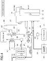
Fig.4 ] is a diagram showing an energy management system in a power generation mode. - [
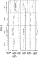
Fig.5 ] is a diagram showing relationships between a system input power, a fuel synthesizing quantity/ fuel consumption quantity, a fuel storage quantity, a CO2 storage quantity, a CO2 recovery quantity, and a CO2 heat recovery quantity in the energy management system. - Hereinafter, with reference to the drawings, an energy management system according to an embodiment of the present disclosure will be described.
- As shown in
Fig.1 , the energy management system is provided with a fuel synthesizinggeneration apparatus 10. The fuel synthesizinggeneration apparatus 10 is configured to be capable of switching between the synthesizing operation of hydrocarbon using externally supplied power and a power generation operation using hydrocarbon. The fuel synthesizinggeneration apparatus 10 incudes a fuel synthesizing mode operating as afuel synthesizing apparatus 10a and a power generation mode operating as apower generation apparatus 10b. - The fuel synthesizing
apparatus 10a is configured as a solid oxide electrolytic cell (SOEC) and thepower generation apparatus 10b is configured as a solid oxide fuel cell (SOFC). The fuel synthesizingapparatus 10a is able to electrolyze H2O and CO2 and synthesize hydrocarbon using electrolyzed H2O and CO2. Thepower generation apparatus 10b is able to generate hydrocarbon. - The fuel synthesizing
generation apparatus 10 is provided with anelectrolyte 11 and a pair ofelectrodes electrolyte 11. The fuel synthesizinggeneration apparatus 10 shown inFig.1 is configured as a single cell disposed between the pair ofelectrodes - The
electrolyte 11 is a solid material having oxygen ion conductivity and may be composed of ZrO2 as a zirconia-based oxide, for example. Theelectrodes first electrode 12, Ni and Co or the like are provided as a metal catalyst. Ni and Co serve as a catalyst to promote an electrolytic reaction between CO2 and H2 and a synthesizing reaction of hydrocarbon. For asecond electrode 13, as a metal catalyst, Ni and Pt or the like are provided. Ni and Pt serves as a catalyst to promote a reaction where O2- is coupled with electron to generate O2. - The
electrodes electrodes generation apparatus 10 operates in a fuel synthesizing mode or a power generation mode. Specifically, when the fuel synthesizinggeneration apparatus 10 operates in the fuel synthesizing mode, thefirst electrode 12 serves as cathode, and thesecond electrode 13 serves as anode. When the fuel synthesizinggeneration apparatus 10 operates in the power generation mode, thefirst electrode 12 serves as anode and thesecond electrode 13 serves as cathode. - When the fuel synthesizing
generation apparatus 10 operates in a fuel synthesizing mode, the power is supplied to the fuel synthesizinggeneration apparatus 10 from apower supply apparatus 13 as an external power source. According to the present embodiment, a power generation apparatus utilizing natural energy as thepower supply apparatus 14. As thepower supply apparatus 14, for example, a solar power generation can be used. - When the fuel synthesizing
generation apparatus 10 operates in the power generation mode, the power generated in the fuel synthesizinggeneration apparatus 10 is supplied to the power-consumingapparatus 15. The power-consuming apparatus 15 operates when the power is supplied thereto. For the power-consumingapparatus 15, electrical equipment such as home electric appliances. - When the fuel synthesizing
generation apparatus 10 operates in the fuel synthesizing mode, H2O and CO2 are supplied to the fuel synthesizinggeneration apparatus 10. In the fuel synthesizinggeneration apparatus 10, H2 is generated by electrolysis of H2O and CO is generated by electrolysis of CO2. - H2O is supplied to the fuel synthesizing
generation apparatus 10 from H2O storage unit 20 via the H2O supply passage 21. In the H2O storage unit 20 according to the present embodiment, H2O is stored in a liquid state. The H2O pump 22 that pumps H2O to the fuel synthesizinggeneration apparatus 10 is provided in the H2O supply passage 21. H2O may be supplied to the fuel synthesizinggeneration apparatus 10 in the liquid state. The H2O pump 22 operates based on a control signal from acontrol unit 50 which will be described later. - CO2 is supplied to the fuel synthesizing
generation apparatus 10 from a CO2 storage unit 23 via the CO2 supply passage 24. In the CO2 storage unit 23 according to the present embodiment, CO2 is stored in a liquid state. CO2 stored in the CO2 storage unit 23 is pressurized. - A
pressure adjusting valve 25 is provided in the CO2 supply passage 24. Thepressure adjusting valve 25 serves as a CO2 pressure reducing unit that depressurizes CO2 stored in the CO2 storage unit 23. Thepressure adjusting valve 25 serves as an expansion valve for expanding CO2. Thepressure adjusting valve 25 operates based on the control signal transmitted from thecontrol unit 50 which will be described later. - A
first heat exchanger 26 is provided in a downstream side of the gas flow relative to thepressure adjusting valve 25 in the CO2 supply passage 24. Thefirst heat exchanger 26 is configured as an evaporator serving as a cooling heat exchanger. - The
first heat exchanger 26 is capable of heat-exchange between CO2 flowing through the CO2 supply passage 24 and a heat transfer medium flowing through a first heattransfer medium circuit 27. CO2 depressurized at thepressure adjusting valve 25 absorbs heat from the heat transfer medium flowing through the firstheat transfer medium 27 and evaporates. In thefirst heat exchanger 26, the heat transfer medium is cooled by cold heat generated when CO2 is evaporated. For the heat transfer medium, ethylene glycol solutions can be used. Thefirst heat exchanger 26 serves as a heat recovery unit that recovers cold heat stored in CO2 by the pressure reduction and expansion. - The heat transfer medium cooled by the
first heat exchanger 26 is supplied to a cold utilizingunit 28 via a firstheat transfer circuit 27. The cold utilizingunit 28 is an apparatus that utilizes cold heat generated when CO2 is evaporated, and may be configured as a cooling unit performing indoor-cooling, for example. - When the fuel synthesizing
generation apparatus 10 operates in the fuel synthesizing mode, hydrocarbon is synthesized from H2 and CO generated by electrolysis. The synthesized hydrocarbon is exhausted from the fuel synthesizinggeneration apparatus 10 as a fuel synthesizing exhaust gas containing the synthesized hydrocarbon. The hydrocarbon contained in the fuel synthesizing exhaust gas is, for example, methane. The hydrocarbon is used as a fuel when the fuel synthesizinggeneration apparatus 10 operates in the power generation mode. - The fuel synthesizing exhaust gas passes through the fuel synthesizing
exhaust gas passage 29. In the fuel synthesizingexhaust gas passage 29, afuel separation unit 30 is provided. Thefuel separation unit 30 separates hydrocarbon from the fuel synthesizing exhaust gas. The separation of hydrocarbon from the fuel synthesizing exhaust gas can be a distilled separation, for example. - The hydrocarbon separated from the
fuel separation unit 30 is stored as a fuel in afuel storage unit 31. Thefuel storage unit 31 stores hydrocarbon in a liquid state. - When the fuel synthesizing
generation apparatus 10 operates in the power generation mode, the fuel stored in thefuel storage unit 31 is supplied to a reformingapparatus 32. The reformingapparatus 32 generates H2 and CO from hydrocarbon by a reforming reaction. The reformingapparatus 32 operates based on the control signal transmitted from thecontrol unit 50 which will be described later. H2 and CO generated in the reformingapparatus 32 is supplied to thefuel synthesizing apparatus 10 via a reformingfuel supply passage 33. - When the fuel synthesizing
generation apparatus 10 operates in the power generation mode, a power generation exhaust gas containing CO2 and H2O is exhausted from the fuel synthesizinggeneration apparatus 10. The power generation exhaust gas passes through the power generationexhaust gas passage 34. The power generation exhaust gas passes through the power generationexhaust gas passage 34. - In the power generation
exhaust gas passage 34, a H2O separation unit 35 is provided. The H2O separation unit 35 is supplied with the power generation exhaust gas containing CO2 and H2O. The H2O separation unit 35 separates H2O from the power generation exhaust gas. For the H2O separation unit 35, for example, a gas-liquid separator can be used. - A CO2 recovering unit 36 is provided in a downstream side of the gas flow relative to the H2
O separation unit 35 in the power generationexhaust gas passage 34. The CO2 recovering unit 36 is supplied with power generation exhaust gas. The CO2 recovering unit 36 separates CO2 from the power generation exhaust gas. The CO2 recovering unit 36 according to the present embodiment repeatedly performs absorption and desorption of CO2, thereby separating CO2 from the power generation exhaust gas and recovering the CO2. - The CO2 recovered by the CO2 recovering unit 36 is supplied to the CO2 recovering unit 23 via a CO2 recovering passage 37. In the CO2 recovering passage 37, a
compressor 38 is provided. thecompressor 38 operates based on the control signal transmitted from thecontrol unit 50 which will be described later. - The CO2 recovered by the CO2 recovering unit 36 is compressed by the
compressor 38 and supplied to the CO2 storage unit 23. Asecond heat exchanger 39 is provided in a downstream side of the gas flow relative to thecompressor 38 in the CO2 recovering passage 37. Thesecond heat exchanger 39 is a condenser serving as a heat exchanger for heating. - The
second heat exchanger 39 is capable of exchanging between CO2 flowing through the CO2 recovering passage 37 and heat transfer medium flowing through the second heattransfer medium circuit 40. CO2 compressed in thecompressor 38 is radiated to the heat transfer medium flowing through the secondheat transfer medium 40 and condensed. In thesecond heat exchanger 39, the heat transfer medium is heated by heat generated when CO2 is condensed. For the heat transfer medium, for example, ethylene glycol solution can be used. Thesecond heat exchanger 39 serves as a heat recovering unit that recovers heat stored in CO2 by the compressing. - The heat transfer medium cooled by the
second heat exchanger 39 is supplied to aheat utilizing unit 41 via the secondheat transfer medium 40. Theheat utilizing unit 41 utilizes heat generated when CO2 is compressed. - The
heat utilizing unit 41 can be configured as a heating apparatus that heats air used for an indoor air-conditioning with a heat recovered by thesecond heat exchanger 39. Alternatively, theheat utilizing unit 41 can be configured as a water heating apparatus in which water is heated by heat recovered by thesecond heat exchanger 39, thereby generating hot water. - Further, the
heat utilizing unit 41 can be configured as a H2O heating apparatus that heats H2O to be supplied to the fuel synthesizinggeneration apparatus 10 from the H2O storage unit 20 with the heat recovered by thesecond heat exchanger 39. Thus, H2O as water vapor can be supplied to thefuel synthesizing apparatus 10. - Further, the
heat utilizing unit 41 can be configured as a heating apparatus that heats thefuel synthesizing apparatus 10 with a heat recovered by thesecond heat exchanger 39. Thus, heat quantity required for a case where the fuel synthesizinggeneration apparatus 10 operates in the fuel synthesizing mode or the power generation mode can be supplemented. - Also, the
heat utilizing unit 41 can be configured as a heating apparatus that heats the reformingapparatus 32 with heat recovered by the second exchanger. Thus, the heat quantity required for the reforming reaction in the reformingapparatus 32 can be supplemented - As shown in
Fig.2 , the energy management system is provided with acontrol unit 50. Thecontrol unit 50 is configured of a known microcomputer including CPU, ROM, RAM and the like, and peripheral circuit thereof. Thecontrol unit 50 performs various calculations and processing based on an air conditioning control program stored in the ROM, and controls operations of variouscontrol object equipment control unit 50, various sensors and the like which are not shown are connected. - Next, an operation of an energy management system according to the present embodiment will be described.
- With reference to
Fig.3 , the fuel synthesizing mode will be described. The fuelsynthesizing generation apparats 10 operates as afuel synthesizing apparatus 10a. In the fuel synthesizing mode, the power is supplied to the fuel synthesizinggeneration apparatus 10 from thepower supply apparatus 14. - In the fuel synthesizing mode, H2O and CO2 are supplied to the
first electrode 12 of the fuel synthesizinggeneration apparatus 10. H2O stored in the H2O storage unit 20 is supplied to the fuel synthesizinggeneration apparatus 10 by activating the H2O pump 22. CO2 stored in the CO2 storage unit 23 is supplied to thefuel synthesizing apparatus 10 by opening thepressure adjusting valve 25. - The CO2 depressurized at the
pressure adjusting valve 25 evaporates at thefirst heat exchanger 26, and heat transfer medium flowing through the first heattransfer medium circuit 27 is cooled by vaporized latent heat thereof. The heat transfer medium cooled at thefirst heat exchanger 26 is supplied to the cold utilizingunit 28 via the firstheat transfer circuit 27. The cold heat generated by pressure reduction and expansion of CO2 is utilized by the cold utilizingunit 28. - In the fuel synthesizing mode, the
first electrode 12 of the fuel synthesizinggeneration apparatus 10 serves as a cathode and the following reactions occur. -
H2O + 2e- → H2 + O2-
CO2 + 2e- → CO + O2-
-
3H2 + CO → CH4 + H2O
- The electrolyte reaction is co-electrolysis reaction in which H2O and CO2 are simultaneously electrolyzed. According to the fuel synthesizing reaction of the present embodiment, CH4 is synthesized as hydrocarbon. O2- generated in the electrolyte reaction of the
first electrode 12 propagates through theelectrolyte 11 and reaches thesecond electrode 13. In the fuel synthesizing mode, thesecond electrode 13 serves as an anode in which O2-and electron are coupled to generate O2. - In the fuel synthesizing reaction, CH4 is synthesized from H2 and CO which are generated with the electrolyte reaction. CH4 generated at the
first electrode 12 is exhausted as the fuel synthesizing exhaust gas from the fuel synthesizinggeneration apparatus 10 via the synthesizingexhaust gas passage 29. CH4 contained in the fuel synthesizing exhaust gas is separated at thefuel separation unit 30 and stored in the fuel storage as a hydrocarbon fuel. The fuel synthesizing exhaust gas remained after separation of CH4 is exhausted outside. - Next, with reference to
Fig.4 , power generation mode will be described. In the power generation mode, the fuel synthesizinggeneration apparatus 10 operates as thepower generation apparatus 10b. The power generated in the fuel synthesizinggeneration apparatus 10 is supplied to the power-consumingapparatus 15. - In the power generation mode, H2 and CO are supplied to the
first electrode 12 from the reformingapparatus 32. Further, air containing O2 is supplied to thesecond electrode 13. - In the power generation mode, the
second electrode 13 serves as a cathode, in which electron is separated from O2 in the air to generate O2-. O2-generated at thesecond electrode 13 propagates through theelectrolyte 11 and reaches thefirst electrode 12. - In the power generation mode, the
first electrode 12 serves as an anode and the following reactions occur.
H2 + O2-+ 2e- → H2O
CO + O2-+ 2e- → CO2
- H2O and CO2 generated at the
first electrode 12 is exhausted as the power generation exhaust gas from the fuel synthesizinggeneration apparatus 10 via the power generationexhaust gas passage 34. H2O contained in the power generation exhaust gas is separated at the H2O separation unit 35 and stored in the H2O storage unit 20. CO2 contained in the power generation exhaust gas is separated at the CO2 recovering unit 36 and supplied to thecompressor 38 via the CO2 recovering passage 37. The power generation exhaust gas remained after separating H2O and CO2 is exhausted outside. - CO2 separated at the CO2 recovering unit 36 is compressed at the
compressor 38 and supplied to the CO2 storage unit 23. CO2 compressed at thecompressor 38 is condensed at thesecond heat exchanger 39, and heat transfer medium flowing through the second heattransfer medium circuit 40 is heated. The heat transfer medium heated at thesecond heat exchanger 39 is supplied to theheat utilizing unit 41. The cold generated by compressing CO2 is utilized by theheat utilizing unit 41 - Next with reference to
Fig.5 , a system input power, a fuel synthesizing quantity and a fuel consumption quantity, a fuel storage quantity, CO2 recovery quantity, CO2 heat recovery quantity of the energy management system will be described. - Since the
power supply apparatus 14 according to the present embodiment performs power generation utilizing natural energy, the power generation capability varies depending on the seasons. Hence, as shown inFig.5 , the energy management system according to the present embodiment changes operation mode between the fuel synthesizing mode and the power generation mode. - In the spring, summer and autumn where the power generation capability of the
power supply apparatus 14 becomes large due to abundant sunlight, the fuel synthesizinggeneration apparatus 10 operates in the fuel synthesizing mode to generate hydrocarbon, and stores the energy as the hydrocarbon. On the other hand, in the winter where the power generation capability utilizing natural energy becomes low and the power consumption of the power-consumingapparatus 15 increases for heating, the fuel synthesizinggeneration apparatus 10 operates in the power generation mode utilizing the hydrocarbon to perform power generation. - The system input power refers to power supplied to the fuel synthesizing
generation apparatus 10 from thepower supply apparatus 14 or power supplied to the power-consumingapparatus 15 from the fuel synthesizinggeneration apparatus 10. The system input power in the spring, the summer and autumn are proportional to the power generation quantity of thepower supply apparatus 14, and the system input power in the winter is proportional to the power consumption quantity of the power-consumingapparatus 15. - The fuel generation quantity refers to a quantity of hydrocarbon generated in the fuel synthesizing
generation apparatus 10 during the fuel synthesizing mode. The fuel consumption quantity refers to a quantity of hydrocarbon utilized in the fuel synthesizinggeneration apparatus 10 during the power generation mode. The fuel generation quantity is proportional to the power generation quantity of thepower supply apparatus 14. The fuel consumption quantity is proportional to the power consumption quantity. - The fuel storage quantity refers to a storage quantity of hydrocarbon in the
fuel storage unit 31. In the fuel synthesizing mode, hydrocarbon is generated, thereby increasing the fuel storage quantity in thefuel storage unit 31. In the power generation mode, hydrocarbon is consumed, thereby reducing the fuel storage quantity of thefuel storage unit 31. - CO2 storage quantity refers to a storage quantity of CO2 in the CO2 storage unit 23. In the fuel synthesizing mode, CO2 storage quantity in the CO2 storage unit 23 decreases because CO2 is used for synthesizing hydrocarbon in the fuel synthesizing
generation apparatus 10. In the power generation mode, CO2 storage quantity in the CO2 storage unit 23 increases because of recovering CO2 generated accompanying the power generation in the fuel synthesizinggeneration apparatus 10. - CO2 recovery quantity refers to CO2 recovery quantity from the fuel synthesizing
generation apparatus 10. In the fuel synthesizing mode, the CO2 recovery quantity is on the negative side for using CO2 in the hydrocarbon synthesizing in the fuel synthesizinggeneration apparatus 10. In the power generation mode, the CO2 recovery quantity is on the positive side for recovering CO2 generated accompanying with the power generation in the fuel synthesizinggeneration apparatus 10. - The CO2 heat recovery quantity refers to a quantity of heat capable of being recovered from CO2. In the fuel synthesizing mode, since cold heat is generated accompanying evaporation of depressurized CO2, the CO2 heat recovery quantity is in the negative side. In the power generation mode, since heat is generated accompanying with compression of CO2 by the
compressor 38, CO2 heat recovery quantity is in positive side. - The above-described energy management system of the present embodiment recovers CO2 from the exhaust gas exhausted from the fuel synthesizing
generation apparatus 10 when generating power using hydrocarbon, and recovers heat generated when compressing CO2 to be stored. Thus, heat generated when compressing CO2 can be effectively utilized and the system efficiency can be improved. - Further, the energy management system of the present embodiment recovers cold heat generated when decompressing CO2, when supplying CO2 to the fuel synthesizing
generation apparatus 10 for the fuel synthesizing. Thus, cold heat generated when decompressing CO2 can be effectively utilized, and the system efficiency can be improved. - Moreover, the energy management system of the present embodiment compresses CO2 recovered from the power generation exhaust gas to be liquefied and stores the liquefied CO2 into the
storage unit 23. Thus, the volume of the recovered CO2 can be significantly lowered, and the storage space for CO2 can be minimized. - The present disclosure is not limited to the above-described embodiments, and may be modified in various manners without departing from the scope of the present disclosure as follows. Further, means disclosed in the above-described respective embodiments may be appropriately combined within an enablement range.
- For example, according to the above-described embodiments, methane is exemplified as a hydrocarbon to be synthesized in the fuel synthesizing
generation apparatus 10. However, different types of hydrocarbon may be synthesized. In the case where the type of catalyst used for thefirst electrode 12 and the reaction temperature are differentiated, the types of hydrocarbon to be synthesized can be differentiated. For different types of hydrocarbon, hydrocarbons of which the number of carbon atoms is larger than that of methane such as methane and propane, or hydrocarbons containing oxygen atoms such as alcohols and ethers can be exemplified. - According to the above-described embodiments, a single fuel
synthesizing generation apparatus 10 is configured to be switched between thefuel synthesizing apparatus 10a and thepower generation apparatus 10b. However, thefuel synthesizing apparatus 10a and thepower generation apparatus 10b can be each provided as an independent apparatus. - Further, according to the above-described embodiments, CO2 in a liquid state is stored in the CO2 storage unit 23. However, CO2 in a gaseous state may be contained and at least part of recovered CO2 may be stored in a liquid state.
- Also, according to the above-described embodiments, hydrocarbon in a liquid state is stored in the
fuel storage unit 31. However, hydrocarbon in a gaseous state may be stored in thefuel storage unit 31. - In the above-described embodiments, heat generated during the operation of the fuel synthesizing
generation apparatus 10 may be utilized for a hot-water supply or the like. - The present disclosure has been described in accordance with the embodiments. However, the present disclosure is not limited to the embodiments and structure thereof. The present disclosure includes various modification examples and modifications within the equivalent configurations. Further, various combinations and modes and other combinations and modes including one element or more or less elements of those various combinations are within the range and technical scope of the present disclosure.
Claims (10)
- An energy management system comprising:a fuel synthesizing apparatus (10a) that generates hydrocarbon from H2O and CO2 using externally supplied power;a power generation apparatus (10b) that generates power using the hydrocarbon;a CO2 recovering unit (36) that recovers CO2 from an exhaust gas exhausted from the power generation apparatus during power generation;a compressor (38) that compresses the CO2 recovered by the CO2 recovering unit;a CO2 storage unit (23) that stores the CO2 compressed by the compressor;a CO2 pressure reducing unit (25) that depressurizes the CO2 stored in the CO2 storage unit in order to supply the fuel synthesizing apparatus therewith; anda heat recovery unit (26, 39) that recovers heat from the CO2, the heat being stored in the CO2 when compressed by the compressor or depressurized by the CO2 pressure reducing unit.
- The energy management system according to claim 1, wherein
the fuel synthesizing apparatus is configured to electrolyze the H2O and CO2 using power supplied by a power supply apparatus (14) that generates power utilizing natural energy. - The energy management system according to claim 1 or 2, wherein
at least a part of the CO2 stored in the CO2 storage unit is in a liquid state. - The energy management system according to any one of claims 1 to 3, whereinthe heat recovery unit is configured to recover heat generated when compressing the CO2 by the compressor; andthe heat recovered by the heat recovery unit is utilized by a heat utilizing unit (41).
- The energy management system according to claim 4, wherein
the heat utilizing unit is configured to heat air used for an indoor air-conditioning unit with the heat recovered by the heat recovery unit. - The energy management system according to claim 4, wherein
the heat utilizing unit is configured to heat water with the heat recovered by the heat recovery unit, thereby generating hot water. - The energy management system according to claim 4, wherein
the heat utilizing unit is configured to heat H2O to be supplied to the fuel synthesizing apparatus with the heat recovered by the heat recovery unit. - The energy management system according to claim 4, wherein
the heat utilizing unit is configured to heat the fuel synthesizing apparatus or the power generation apparatus with the heat recovered by the heat recovery unit. - The energy management system according to any one of claims 1 to 3, whereinthe heat recovery unit is configured to recover cold heat generated when depressurizing CO2 by the CO2 pressure reducing unit; andthe cold heat recovered by the heat recovery unit is utilized by a cold utilizing unit (28).
- The energy management system according to any one of claims 1 to 9, whereinthe fuel synthesizing apparatus and the power generation apparatus are configured of a single fuel-synthesizing generation apparatus (10) capable of switching between a synthesizing operation of hydrocarbon using externally supplied power and a power generation operation using hydrocarbon;the fuel synthesizing generation apparatus is provided with an electrolyte (11) and a pair of electrodes (12, 13) provided at both sides of the electrolyte;the pair of electrodes are configured such that functions thereof are switched between an anode and a cathode depending on whether the fuel synthesizing apparatus operates as the fuel synthesizing apparatus or the power generation apparatus.
Applications Claiming Priority (2)
| Application Number | Priority Date | Filing Date | Title |
|---|---|---|---|
| JP2019123665A JP2021009820A (en) | 2019-07-02 | 2019-07-02 | Energy management system |
| PCT/JP2020/023433 WO2021002184A1 (en) | 2019-07-02 | 2020-06-15 | Energy management system |
Publications (2)
| Publication Number | Publication Date |
|---|---|
| EP3995605A1 true EP3995605A1 (en) | 2022-05-11 |
| EP3995605A4 EP3995605A4 (en) | 2022-10-05 |
Family
ID=74100575
Family Applications (1)
| Application Number | Title | Priority Date | Filing Date |
|---|---|---|---|
| EP20835375.5A Pending EP3995605A4 (en) | 2019-07-02 | 2020-06-15 | Energy management system |
Country Status (5)
| Country | Link |
|---|---|
| US (1) | US12183958B2 (en) |
| EP (1) | EP3995605A4 (en) |
| JP (1) | JP2021009820A (en) |
| CN (1) | CN114127875B (en) |
| WO (1) | WO2021002184A1 (en) |
Families Citing this family (2)
| Publication number | Priority date | Publication date | Assignee | Title |
|---|---|---|---|---|
| JP7520316B2 (en) * | 2019-08-16 | 2024-07-23 | 東京瓦斯株式会社 | Energy storage device |
| JP7808970B2 (en) * | 2022-01-20 | 2026-01-30 | 本田技研工業株式会社 | Electrolysis System |
Family Cites Families (44)
| Publication number | Priority date | Publication date | Assignee | Title |
|---|---|---|---|---|
| JPH0790122B2 (en) * | 1987-05-12 | 1995-10-04 | 日本酸素株式会社 | Extraction method using high-pressure carbon dioxide |
| US7045238B2 (en) * | 2003-03-24 | 2006-05-16 | Ion America Corporation | SORFC power and oxygen generation method and system |
| US7482078B2 (en) * | 2003-04-09 | 2009-01-27 | Bloom Energy Corporation | Co-production of hydrogen and electricity in a high temperature electrochemical system |
| KR101318966B1 (en) * | 2005-03-16 | 2013-10-17 | 퓨얼코어 엘엘씨 | System, methods, and compositions for production of synthetic hydrocarbon compounds |
| US20080138675A1 (en) * | 2006-12-11 | 2008-06-12 | Jang Bor Z | Hydrogen generation and storage method for personal transportation applications |
| WO2008150524A2 (en) * | 2007-06-04 | 2008-12-11 | Bloom Energy Corporation | Structure for high temperature fuel cell system start up and shutdown |
| JP2010062192A (en) | 2008-09-01 | 2010-03-18 | Meisan Kk | Liquefaction and storage of natural energy utilizing dimethylether (dme) |
| US20100314235A1 (en) * | 2009-06-16 | 2010-12-16 | Exxonmobil Research And Engineering Company | High temperature hydropyrolysis of carbonaceous materials |
| EP2501782A1 (en) * | 2009-11-20 | 2012-09-26 | Cri Ehf | Storage of intermittent renewable energy as fuel using carbon containing feedstock |
| JP5558310B2 (en) * | 2010-10-22 | 2014-07-23 | 株式会社東芝 | Carbon dioxide recovery method and carbon dioxide recovery steam power generation system |
| WO2012069636A2 (en) * | 2010-11-26 | 2012-05-31 | Statoil Asa | Sanner cycle energy system and converter |
| GB201202791D0 (en) * | 2012-02-20 | 2012-04-04 | Simpson Robert | Methods and system for energy conversion and generation |
| EP2941475B1 (en) | 2013-01-04 | 2019-06-19 | Saudi Arabian Oil Company | Carbon dioxide conversion to hydrocarbon fuel via syngas production cell harnessed from solar radiation |
| WO2015037625A1 (en) * | 2013-09-12 | 2015-03-19 | 独立行政法人宇宙航空研究開発機構 | Solid polymer power generation or electrolysis method and system |
| FR3024985B1 (en) * | 2014-08-22 | 2020-01-17 | Commissariat A L'energie Atomique Et Aux Energies Alternatives | HIGH TEMPERATURE ELECTROLYSIS OR CO-ELECTROLYSIS PROCESS, PROCESS FOR PRODUCING ELECTRICITY BY SOFC FUEL CELL, INTERCONNECTORS, REACTORS AND RELATED OPERATING METHODS. |
| EP3054519B1 (en) * | 2015-02-03 | 2017-11-08 | Technische Universität München | Reversible fuel cell system and method for operating a fuel cell system |
| US9812723B2 (en) | 2015-02-25 | 2017-11-07 | Fuelcell Energy, Inc. | Power producing gas separation system and method |
| WO2016161998A1 (en) * | 2015-04-08 | 2016-10-13 | Sunfire Gmbh | Production process and production system for producing methane / gaseous and/or liquid hydrocarbons |
| DE102015114613A1 (en) * | 2015-09-01 | 2017-03-02 | Siqens Gmbh | Method and apparatus for parallel condensation and evaporation for a fuel cell system with a condensation / evaporation device and a fuel cell system with such a condensation / evaporation device |
| WO2017075525A1 (en) * | 2015-10-30 | 2017-05-04 | Intelligent Energy Limited | Thin fluid manifolds and methods therefor |
| KR102143864B1 (en) * | 2015-11-16 | 2020-08-12 | 퓨얼 셀 에너지, 인크 | System to capture CO2 from fuel cells |
| CA3005639C (en) * | 2015-11-16 | 2021-05-18 | Fuelcell Energy, Inc. | Energy storage using an rep with an engine |
| JP6640354B2 (en) * | 2015-11-17 | 2020-02-05 | フュエルセル エナジー, インコーポレイテッドFuelcell Energy, Inc. | Hydrogen and carbon monoxide production using REP with partial oxidation |
| WO2017160511A1 (en) * | 2016-03-17 | 2017-09-21 | Exxonmobil Research And Engineering Company | Integrated operation of molten carbonate fuel cells |
| CN105845962B (en) * | 2016-03-30 | 2019-01-18 | 华中科技大学 | Solid oxide fuel cell and electrolytic tank of solid oxide combined generating system |
| DK3491173T3 (en) * | 2016-07-26 | 2022-07-11 | Thyssenkrupp Ind Solutions Ag | PROCESS AND PLANT FOR THE MANUFACTURE OF METHANOL |
| JPWO2018029994A1 (en) * | 2016-08-09 | 2019-02-14 | 本田技研工業株式会社 | Hydrogen treatment equipment |
| WO2018163416A1 (en) * | 2017-03-10 | 2018-09-13 | 株式会社 東芝 | Hydrogen energy utilization system and method for operating same |
| JP6881007B2 (en) * | 2017-05-10 | 2021-06-02 | 株式会社豊田中央研究所 | Power storage and supply system |
| CN116845304A (en) * | 2017-11-22 | 2023-10-03 | 燃料电池能有限公司 | Generating hydrogen using a fuel cell system with REP |
| FR3075832A1 (en) * | 2017-12-22 | 2019-06-28 | Commissariat A L'energie Atomique Et Aux Energies Alternatives | METHOD FOR OPERATING IN STARTING OR STAND-BY MODE OF A POWER-TO-GAS UNIT COMPRISING A PLURALITY OF ELECTROLYSIS REACTORS (SOEC) OR CO-ELECTROLYSIS AT HIGH TEMPERATURE |
| WO2019144135A1 (en) * | 2018-01-22 | 2019-07-25 | Opus-12 Incorporated | System and method for carbon dioxide reactor control |
| US20230202840A1 (en) * | 2018-01-22 | 2023-06-29 | Twelve Benefit Corporation | System and method for carbon dioxide reactor control |
| EP3771023A4 (en) * | 2018-03-19 | 2021-12-15 | GT Co., Ltd. | CARBON DIOXIDE USE SYSTEM AND COMPLEX ENERGY GENERATION SYSTEM WITH IT |
| GB201812568D0 (en) * | 2018-08-01 | 2018-09-12 | Storelectric Ltd | Energy Storage with Hydrogen |
| JP6691247B1 (en) * | 2019-01-22 | 2020-04-28 | 東京瓦斯株式会社 | Reactor and fuel cell power generation system |
| US11495806B2 (en) * | 2019-02-04 | 2022-11-08 | Fuelcell Energy, Inc. | Ultra high efficiency fuel cell power generation system |
| JP7203669B2 (en) * | 2019-03-29 | 2023-01-13 | 大阪瓦斯株式会社 | Electrochemical modules, electrochemical devices and energy systems |
| US11322767B2 (en) * | 2019-04-12 | 2022-05-03 | Bloom Energy Corporation | Solid oxide fuel cell system with hydrogen pumping cell with carbon monoxide tolerant anodes and integrated shift reactor |
| WO2020230417A1 (en) * | 2019-05-14 | 2020-11-19 | パナソニックIpマネジメント株式会社 | Hydrogen system |
| JP2021008655A (en) * | 2019-07-02 | 2021-01-28 | 株式会社デンソー | Energy conversion system |
| US11383977B1 (en) * | 2019-12-17 | 2022-07-12 | Samuel Okechukwu Umealu | Incomplete combustion as a means of reducing carbon dioxide emissions |
| US11685865B2 (en) * | 2020-08-28 | 2023-06-27 | Methylennium Energy Corp. | System and method for production of hydrocarbons from carbon dioxide |
| US20240258546A1 (en) * | 2021-05-27 | 2024-08-01 | Jared Moore | Oxyfuel hybrid electric vehicle |
-
2019
- 2019-07-02 JP JP2019123665A patent/JP2021009820A/en active Pending
-
2020
- 2020-06-15 WO PCT/JP2020/023433 patent/WO2021002184A1/en not_active Ceased
- 2020-06-15 CN CN202080049283.2A patent/CN114127875B/en active Active
- 2020-06-15 EP EP20835375.5A patent/EP3995605A4/en active Pending
-
2022
- 2022-01-03 US US17/567,292 patent/US12183958B2/en active Active
Also Published As
| Publication number | Publication date |
|---|---|
| WO2021002184A1 (en) | 2021-01-07 |
| CN114127875A (en) | 2022-03-01 |
| US20220123338A1 (en) | 2022-04-21 |
| EP3995605A4 (en) | 2022-10-05 |
| JP2021009820A (en) | 2021-01-28 |
| CN114127875B (en) | 2023-10-13 |
| US12183958B2 (en) | 2024-12-31 |
Similar Documents
| Publication | Publication Date | Title |
|---|---|---|
| US11542610B2 (en) | System for high-temperature reversible electrolysis of water comprising a hydride tank coupled with the electrolyser | |
| Chahartaghi et al. | Performance analysis of a combined cooling, heating and power system with PEM fuel cell as a prime mover | |
| US11870050B2 (en) | Thermo-electrochemical convertor with integrated energy storage | |
| CA3028495C (en) | Process for starting mode or stand-by mode operation of a power-to-gas unit comprising a plurality of high-temperature electrolysis (soec) or co-electrolysis reactors | |
| EP2800186B1 (en) | Fuel cell hybrid system | |
| US20030207161A1 (en) | Hydrogen production and water recovery system for a fuel cell | |
| US10087532B2 (en) | Electrochemical compressor utilizing an electrolysis | |
| CN111244501A (en) | Integrated reversible fuel cell system based on dual-function water circulation and electric pile thereof | |
| CN113039153A (en) | Hydrogen system | |
| US8445155B2 (en) | Complex power generation system and method for supplying heated water thereof | |
| US12183958B2 (en) | Energy management system | |
| WO2017173731A1 (en) | Heat pump air conditioner and heating and cooling method using methanol-water reforming electric generator | |
| JP2020149838A (en) | Nitrogen gas generation method and equipment for filtering high-pressure fuel cell exhaust gas | |
| JP2002056880A (en) | Water electrolysis device and solid polymer type fuel cell generating system | |
| KR101828937B1 (en) | Combined power generation system of high-temperature polymer electrolyte membrane fuel cell with a rankine cycle system | |
| JP2006236599A (en) | Water recovery method for fuel cell power generator | |
| JP2002056879A (en) | Water electrolysis device and phosphoric acid type fuel cell generating system | |
| Musa et al. | Operating conditions on the performances of SOFC fuelled with methane | |
| EP4489152B1 (en) | Reversible solid oxide cell system | |
| KR100724397B1 (en) | Energy supply device using fuel cell | |
| WO2025032310A1 (en) | A methanation method and system | |
| WO2026047273A1 (en) | Solid oxide steam electrolysis system and method | |
| US20070259223A1 (en) | Capturing heat from a fuel cell stack | |
| HK1231523A1 (en) | Electrochemical compressor utilizing an electrolysis | |
| JPH01248475A (en) | Fuel cell power plant |
Legal Events
| Date | Code | Title | Description |
|---|---|---|---|
| STAA | Information on the status of an ep patent application or granted ep patent |
Free format text: STATUS: THE INTERNATIONAL PUBLICATION HAS BEEN MADE |
|
| PUAI | Public reference made under article 153(3) epc to a published international application that has entered the european phase |
Free format text: ORIGINAL CODE: 0009012 |
|
| STAA | Information on the status of an ep patent application or granted ep patent |
Free format text: STATUS: REQUEST FOR EXAMINATION WAS MADE |
|
| 17P | Request for examination filed |
Effective date: 20220110 |
|
| AK | Designated contracting states |
Kind code of ref document: A1 Designated state(s): AL AT BE BG CH CY CZ DE DK EE ES FI FR GB GR HR HU IE IS IT LI LT LU LV MC MK MT NL NO PL PT RO RS SE SI SK SM TR |
|
| STAA | Information on the status of an ep patent application or granted ep patent |
Free format text: STATUS: EXAMINATION IS IN PROGRESS |
|
| A4 | Supplementary search report drawn up and despatched |
Effective date: 20220901 |
|
| RIC1 | Information provided on ipc code assigned before grant |
Ipc: F17C 9/00 20060101ALI20220826BHEP Ipc: C25B 15/08 20060101ALI20220826BHEP Ipc: C25B 3/26 20210101ALI20220826BHEP Ipc: C25B 3/07 20210101ALI20220826BHEP Ipc: C25B 3/03 20210101ALI20220826BHEP Ipc: C01B 3/24 20060101ALI20220826BHEP Ipc: C25B 1/04 20210101ALI20220826BHEP Ipc: H01M 8/12 20160101ALI20220826BHEP Ipc: H01M 8/0662 20160101ALI20220826BHEP Ipc: H01M 8/0656 20160101ALI20220826BHEP Ipc: H01M 8/04 20160101ALI20220826BHEP Ipc: H01M 8/00 20160101AFI20220826BHEP |
|
| 17Q | First examination report despatched |
Effective date: 20220913 |
|
| DAV | Request for validation of the european patent (deleted) | ||
| DAX | Request for extension of the european patent (deleted) | ||
| REG | Reference to a national code |
Ref country code: DE Ref legal event code: R079 Free format text: PREVIOUS MAIN CLASS: C25B0009000000 Ipc: H01M0008000000 |
|
| RIC1 | Information provided on ipc code assigned before grant |
Ipc: H01M 8/04007 20160101ALI20241220BHEP Ipc: C01B 3/34 20060101ALI20241220BHEP Ipc: F17C 9/00 20060101ALI20241220BHEP Ipc: C25B 15/08 20060101ALI20241220BHEP Ipc: C25B 3/26 20210101ALI20241220BHEP Ipc: C25B 3/07 20210101ALI20241220BHEP Ipc: C25B 3/03 20210101ALI20241220BHEP Ipc: C01B 3/24 20060101ALI20241220BHEP Ipc: C25B 1/04 20210101ALI20241220BHEP Ipc: H01M 8/12 20160101ALI20241220BHEP Ipc: H01M 8/0662 20160101ALI20241220BHEP Ipc: H01M 8/0656 20160101ALI20241220BHEP Ipc: H01M 8/04 20160101ALI20241220BHEP Ipc: H01M 8/00 20160101AFI20241220BHEP |