EP3995373A1 - Air dryer with direct solenoid control - Google Patents
Air dryer with direct solenoid control Download PDFInfo
- Publication number
- EP3995373A1 EP3995373A1 EP20206560.3A EP20206560A EP3995373A1 EP 3995373 A1 EP3995373 A1 EP 3995373A1 EP 20206560 A EP20206560 A EP 20206560A EP 3995373 A1 EP3995373 A1 EP 3995373A1
- Authority
- EP
- European Patent Office
- Prior art keywords
- unit
- air dryer
- exhaust valve
- compressed air
- valve
- Prior art date
- Legal status (The legal status is an assumption and is not a legal conclusion. Google has not performed a legal analysis and makes no representation as to the accuracy of the status listed.)
- Granted
Links
Images
Classifications
-
- B—PERFORMING OPERATIONS; TRANSPORTING
- B60—VEHICLES IN GENERAL
- B60T—VEHICLE BRAKE CONTROL SYSTEMS OR PARTS THEREOF; BRAKE CONTROL SYSTEMS OR PARTS THEREOF, IN GENERAL; ARRANGEMENT OF BRAKING ELEMENTS ON VEHICLES IN GENERAL; PORTABLE DEVICES FOR PREVENTING UNWANTED MOVEMENT OF VEHICLES; VEHICLE MODIFICATIONS TO FACILITATE COOLING OF BRAKES
- B60T17/00—Component parts, details, or accessories of power brake systems not covered by groups B60T8/00, B60T13/00 or B60T15/00, or presenting other characteristic features
- B60T17/002—Air treatment devices
- B60T17/004—Draining and drying devices
-
- B—PERFORMING OPERATIONS; TRANSPORTING
- B01—PHYSICAL OR CHEMICAL PROCESSES OR APPARATUS IN GENERAL
- B01D—SEPARATION
- B01D53/00—Separation of gases or vapours; Recovering vapours of volatile solvents from gases; Chemical or biological purification of waste gases, e.g. engine exhaust gases, smoke, fumes, flue gases, aerosols
- B01D53/26—Drying gases or vapours
- B01D53/261—Drying gases or vapours by adsorption
-
- B—PERFORMING OPERATIONS; TRANSPORTING
- B01—PHYSICAL OR CHEMICAL PROCESSES OR APPARATUS IN GENERAL
- B01D—SEPARATION
- B01D2259/00—Type of treatment
- B01D2259/45—Gas separation or purification devices adapted for specific applications
- B01D2259/4566—Gas separation or purification devices adapted for specific applications for use in transportation means
Definitions
- the present invention relates to an air dryer.
- pneumatic systems are usually used for brake, suspension and other auxiliary systems.
- the necessary compressed air is delivered by a reciprocating compressor, and an air supply system is equipped with an air dryer unit, which serves to decrease the water content of the air delivered by the compressor.
- Typical air dryer units use a desiccant to absorb the humidity.
- the desiccant cartridge of the air dryer needs to be regenerated after filling phase. During regeneration, a backward flow of dried air is led through the desiccant. Valves are used to control the regeneration process and to exhaust the air to the atmosphere.
- the regeneration is realized by an exhaust valve, which is pneumatically controlled by a pilot valve.
- suspension and trailer brake systems may still operate with compressed air.
- the air dryer unit comprises a desiccant unit, which is arranged downstream from a compressed air inlet and upstream from a compressed air outlet, and an exhaust valve, which is arranged between the compressed air inlet and the desiccant unit.
- the exhaust valve is connected to a main exhaust.
- the exhaust valve is electromechanically operated.
- the invention is based on the basic idea to control the exhaust valve of the system for regeneration directly, instead of controlling it indirectly via a pilot valve.
- the exhaust valve is therefore configured as an electrically controlled valve, in particular a solenoid valve, instead of a pneumatically controlled valve.
- a direct control is used to control the airflow through the air dryer, either in a direction from the compressor to the vehicle's compressed air system, or in the opposite direction from the compressed air system to an exhaust.
- the filling and exhausting of the compressed air system can be realized through an electromechanically operated valve, such as a solenoid valve, which controls the regeneration of the air dryer directly, without an additional pilot valve.
- the exhaust valve may be situated in a mainstream line of the system, such that both the filling of the system and the exhausting or regeneration of the air dryer unit are realized directly through the exhaust valve.
- the air dryer unit of the invention is optimized for utility vehicles with low air-demand, such as electric vehicle solutions.
- the air dryer unit of the invention can be fixed directly onto the compressor, which provides compressed air.
- the compressed air inlet may be configured for receiving compressed air from a compressor unit, in particular from a compressor.
- the compressed air outlet may be configured for providing compressed air to a unit of the vehicle or a unit that is connected to the vehicle, such as a trailer.
- compressed air is provided to a consumer unit.
- the main exhaust may be configured for releasing compressed air from the air dryer unit to an atmosphere surrounding the air dryer unit.
- the main exhaust may be configured for de-aerating a pneumatic system that is connected to the air dryer unit.
- the desiccant unit may be configured following known principles of a unit comprising a desiccant material, which dries the air flowing from the compressed air inlet towards the pneumatic system of the vehicle and/or connected external systems.
- the moist incoming air flowing through the desiccant - in particular during a filling phase of the system - deposits humidity in the desiccant material.
- contaminations and in particular particles in the compressed air can be deposited in the desiccant material of the desiccant unit.
- a desiccant cartridge can be used for the desiccant unit.
- dry air may be used to regenerate the desiccant material, when it has absorbed a certain amount of humidity: Dry air from the pneumatic system is direct backwards towards and through the desiccant unit, and released through the main exhaust. In this regeneration phase, humidity is released from the desiccant material and into the atmosphere surrounding the exhaust.
- a main check valve is arranged between the desiccant unit and the compressed air outlet.
- a throttle is arranged in parallel to the main check valve in a bypass air duct.
- the throttle may be configured as a nozzle or a similar element.
- the system is advantageously protected from an overly large airflow in a direction from the pneumatic system towards the desiccant unit and the compressed air inlet.
- the air dryer unit has two operational states, namely a filling state and a regeneration state, wherein in the filling state the exhaust valve connects the desiccant unit to the compressed air inlet, and in the regeneration state the exhaust valve connects the desiccant unit to the main exhaust.
- the phases for filling and regeneration are advantageously easily defined by the state of the exhaust valve: If a connection is provided from the compressed air inlet towards the desiccant unit, air flows through the desiccant unit towards the pneumatic system of the vehicle and/or other connected systems. On the other hand, if a connection is provided between the desiccant unit and the main exhaust, air is flowing from the pneumatic system towards the exhaust, thus regenerating the desiccant unit.
- the exhaust valve may be configured with two states, namely one state in which the connection from the compressed air inlet towards the desiccant unit is provided, thus defining the filling state, and another state, in which the connection from the desiccant unit to the main exhaust is provided, thus defining the regeneration state of the air dryer unit.
- the air dryer unit further comprises a control unit, which is configured to output an electrical control signal, for directly controlling the exhaust valve.
- the air dryer unit can be operated without the need for further element, such as an additional pilot valve.
- directly controlling the exhaust valve may be understood as a control without using a pilot valve.
- a pilot valve such as a relay valve, is pneumatically connected to a control input of the exhaust valve.
- the pilot valve is electrically controlled and outputs a pneumatic control pressure or pneumatic control signal
- the exhaust valve is pneumatically controlled and this subject to an indirect control via the pilot valve.
- control unit is configured to activate the filling state or the regeneration state of the air dryer unit by controlling the exhaust valve.
- the exhaust valve is a solenoid valve.
- the exhaust valve may be configured easily and in a very robust way to control the states of the air dryer unit and have efficient transition between filling and regeneration.
- the exhaust valve may have different types of electromechanically operated valves.
- the exhaust valve is a 3/2-way valve.
- a solenoid 3/2-way valve may be used, for example a 3/2-way normally open solenoid valve.
- the exhaust valve may be differently configured as another type of valve.
- 3/2- or 3/3-way valves can be used.
- the exhaust valve may be of a normally opened or normally closed type.
- the air dryer unit further comprises a secondary check valve, which is arranged upstream from the desiccant unit, wherein the secondary check valve is configured to prevent an air back-flow to the compressed air inlet.
- the secondary check valve unit is arranged between the compressed air inlet of the air dryer unit and the exhaust valve.
- the secondary check valve may be arranged in a connecting line from a compressor, which provides the compressed air to the air dryer unit, before the compressed air reaches the desiccant unit.
- the exhaust valve is not controlled by another valve, in particular not by a pilot valve.
- the air dryer unit is advantageously realized with fewer components and thus lighter and more robust than common configurations, which use a pilot valve.
- the method for operating an air dryer unit comprises receiving a control signal and, depending on the control signal, activating a filling state or a regeneration state of the air dryer unit.
- a filling state is activated
- an exhaust valve is controlled to connect a desiccant unit to a compressed air inlet.
- the regeneration state is activated, the exhaust valve is controlled to connect the desiccant unit to a main exhaust.
- the control signal is an electrical signal and the exhaust valve is controlled electromechanically.
- the method is in particular configured to operate the air dryer unit according to the present description and/or according to the present claims.
- the method has the same advantages as the air dryer unit according to the invention.
- control signal is an electrical control signal.
- the control signal may be generated by a control unit of the air dryer unit and/or by an external control unit.
- control signal is received by the exhaust valve.
- the exhaust valve may then be configured to switch between a first state, in particular a filling state, in which the desiccant unit is connected to a compressed air inlet, and a second state, in particular a regeneration state, where the desiccant unit is connected to a main exhaust.
- FIG. 1 an embodiment of the air dryer unit is described.
- the air dryer system 1 is integrated into a utility vehicle 5.
- the air dryer unit 1 has a housing.
- the air dryer unit 1 has at least one compressed air inlet 6, in particular an inlet port.
- the air dryer unit 1 has at least one compressed air outlet 7, in particular an outlet port.
- the air dryer unit 1 also has a main exhaust 15, in particular a main exhaust port.
- the air dryer unit 1 further has an exhaust valve 11.
- the exhaust valve 11 is a solenoid valve.
- the exhaust valve 11 is configured as a 3/2-way valve.
- the exhaust valve 11 can be another type of electromechanically operated valve.
- the air dryer unit 1 has a desiccant unit 12.
- the air dryer unit 1 has a main check valve 13.
- the air dryer unit 1 has a nozzle 14 or throttle 14.
- the nozzle 14 can be integrated into the main check valve 13. Furthermore, the main check valve 13 and the nozzle 14 can be incorporated into a common unit, e.g., within one common housing.
- the air dryer unit 1 is connected to a compressor 2.
- the compressor 2 is connected at the compressed air inlet 6.
- a delivery line of the compressor 2 is connected to the compressed air inlet 6 directly with a flange or indirectly with a suitable piping.
- the compressed air outlet 7 is connected to a compressed air system 3.
- the compressed air system 3 is integrated into the utility vehicle 5 and supplies different consumer systems with compressed air, such at the vehicle's brakes, a suspension and/or an auxiliary air system.
- the compressed air system 3 can provide compressed air to connected external systems, such as an air system of a trailer.
- the compressed air inlet 6 is connected with the desiccant unit 12.
- the desiccant unit 12 is provided with a desiccant material, which takes up humidity from air, which is flowing through the desiccant unit 12. In particular, moisture is removed from compressed air, as it is provided by the compressor 2 and received through the compressed air inlet 6.
- the desiccant unit 12 can have a desiccant cartridge.
- a main check valve 13 Downstream from the desiccant 12, a main check valve 13 is arranged.
- the compressed air outlet 7 is provided, where the compressed air system 3 is connected.
- compressed air is provided by the compressor 2, enters the air dryer unit 1 through the compressed air inlet 6, passes the desiccant unit 12, passes the main check valve 13 and reaches the compressed air system 3 through the compressed air outlet 7.
- the main check valve 13 ensures that air can only pass in a direction from the compressed air inlet 6 to the compressed air outlet 7.
- the nozzle 14 is provided in a bypass line 8 in this embodiment.
- the bypass line is configured to bypass the main check valve 13, i.e., it is connected upstream the main check valve 13 at one end and downstream the main check valve 13 at the other end.
- bypass line 8 By providing the bypass line 8 with the nozzle 14, a limited airflow can be allowed without passing the main check valve 13. In particular, a limited airflow from the compressed air outlet 7 to the desiccant unit 12 is possible.
- the invention is based on the idea that different operational states of the air dryer unit 1 can be activated and an airflow within the air dryer unit 1 can be re-directed by switching an electrically controlled valve, instead of controlling a pilot valve or relay valve, which then provides a pneumatic control signal to another valve in order to change the air flow in the air dryer unit 1.
- no pilot valve is used to control the exhaust valve 11.
- an electrical control signal can directly switch the exhaust valve 11 and activate the different operational states of the air dryer unit 1, in particular a filling state and a regeneration state.
- the exhaust valve 11 is connected to the compressed air inlet 6, the desiccant unit 12 and the main exhaust 15.
- the control input of the exhaust valve is electrically connected to the control unit 10.
- a filling state and a regeneration state can be activated for the air dryer unit 1.
- the filling state and the regeneration state are operational states of the air dryer unit 1.
- control unit 10 which is configured to generate an electrical control signal and apply it to the exhaust valve's 11 control input.
- the fill state is activated.
- the exhaust valve 11 is in its resting position, i.e., it connects the compressed air inlet 6 to the desiccant unit 12.
- the airflow can pass the main check valve 13 and reaches the compressed air system 3 via the compressed air outlet 7.
- the compressed air system 3 is thus filled with compressed air.
- the exhaust valve 11 When the control unit 10 generates a control signal to activate the regeneration state, the exhaust valve 11 is controlled such that it switches its position and connects the desiccant unit 12 to the main exhaust 15.
- the regeneration state can be activated after a given time, where the air dryer unit 1 is operated in the filling state, depending on the volume of compressed air passing the desiccant unit 12 or depending on a humidity of the compressed air that is provided to the compressed air system 3.
- connection between the desiccant unit 12 and the main exhaust 15 leads to a deaeration of the desiccant unit 12 and connected elements.
- the main check valve 13 prevents airflow back from the compressed air system 3 to the desiccant 12, but the nozzle 14 allows a certain amount of such airflow through the bypass line 8.
- the control unit 10 may also provide a control signal to stop the compressor 2, when the regeneration state is activated.
- this control system form the compressor 2 can be an electrical signal.
- control unit 10 At the end of the regeneration state, the control unit 10 generates a signal to activate the filling state again, and the exhaust valve 11 is controlled to switch again and connect the desiccant unit 12 to the compressed air inlet 6.
- the end of the regeneration state and/or the transition to the filling state can be triggered in different ways: For example, the regeneration state can be ended after a given time, where the air dryer unit 1 is operated in the regeneration state, depending on the volume of compressed air passing the desiccant unit 12 and leaving through the main exhaust 15.
- FIG. 2 another embodiment of the air dryer unit 1 is described.
- This embodiment is structurally very similar to the embodiment described with relation to Fig. 1 .
- the same reference numerals have been used and the embodiment of Fig. 1 is explained in further detail by this embodiment.
- the air dryer unit 1 has a secondary check valve 16 arranged upstream from the exhaust valve 11, i.e. arranged between the compressed air inlet 6 and the exhaust valve 11.
- pressurized air from the compressor 2 may pass the secondary check valve 16 and reach the desiccant unit 12 via the exhaust valve 11.
- the dried air then passes the main check valve 13 and is delivered to the compressed air system 3 through the compressed air outlet 7.
- the compressor 2 stops the air delivery, and the air dryer unit stays in a stand-by phase.
- the secondary check valve 16 prevents a backflow from the compressed air system 3 towards the compressor 2.
- the vehicle brake, a suspension system and auxiliary compressed air system can consume the pressurized air prepared by the air dryer unit 1 and provided to the compressed air system 3.
- the compressor 2 switches back to the filling phase, i.e., the compressor 2 pumps again pressurized air through the compressed air inlet 6.
- the dried air from downstream the desiccant unit 12 flows back from the compressed air system 3, expands on a regeneration nozzle 14, and cleans the desiccant unit 12 from the moisture and contamination.
- the regeneration air exits to the atmosphere at the main exhaust port 15.
Landscapes
- Engineering & Computer Science (AREA)
- Chemical & Material Sciences (AREA)
- Analytical Chemistry (AREA)
- General Chemical & Material Sciences (AREA)
- Oil, Petroleum & Natural Gas (AREA)
- Chemical Kinetics & Catalysis (AREA)
- Transportation (AREA)
- Mechanical Engineering (AREA)
- Valves And Accessory Devices For Braking Systems (AREA)
- Drying Of Gases (AREA)
Abstract
Description
- The present invention relates to an air dryer.
- In utility vehicles, pneumatic systems are usually used for brake, suspension and other auxiliary systems. The necessary compressed air is delivered by a reciprocating compressor, and an air supply system is equipped with an air dryer unit, which serves to decrease the water content of the air delivered by the compressor.
- Typical air dryer units use a desiccant to absorb the humidity. The desiccant cartridge of the air dryer needs to be regenerated after filling phase. During regeneration, a backward flow of dried air is led through the desiccant. Valves are used to control the regeneration process and to exhaust the air to the atmosphere.
- In current applications, the regeneration is realized by an exhaust valve, which is pneumatically controlled by a pilot valve. With such a setup, the large volume flow of compressed air, which is typically provided, can be efficiently directed by switching the exhaust valve.
- Due to the spreading use of electric drive solutions, typical modern compressors deliver less air than the widespread systems according to the state of the art. Also, it is expected for future that electric brake systems will appear, which will work without compressed air. For example, electric vehicles demand lower air volumes for a service brake due to regenerative braking. Also, off-engine compressor solutions can be used with lower volumetric flow. As a consequence, the necessary air volume in the utility vehicle system is assumed to decrease.
- It is expected that modern vehicles will use a friction brake increasingly only for emergency cases. Instead, electromechanical brakes are introduced, which will eliminate or at least reduce the air demand in service brake lines significantly.
- However, suspension and trailer brake systems may still operate with compressed air.
- In addition to that, particularly compact, small air treatment modules are needed in electric vehicles due to the large space required by the battery package.
- Furthermore, currently used air dryer solutions include many components and different units for every function. Therefore, current air dryers are complicated, heavy and large.
- Thus, it is the problem of the invention to improve an air dryer unit advantageously, in particular with respect to cost efficiency, ease of construction, lower complexity and lower need for assembly space.
- According to the invention, this problem is solved by an air dryer unit for a utility vehicle according to claim 1.
- According to this, the air dryer unit comprises a desiccant unit, which is arranged downstream from a compressed air inlet and upstream from a compressed air outlet, and an exhaust valve, which is arranged between the compressed air inlet and the desiccant unit. Therein, the exhaust valve is connected to a main exhaust. Also, the exhaust valve is electromechanically operated.
- The invention is based on the basic idea to control the exhaust valve of the system for regeneration directly, instead of controlling it indirectly via a pilot valve. The exhaust valve is therefore configured as an electrically controlled valve, in particular a solenoid valve, instead of a pneumatically controlled valve. Thus, a direct control is used to control the airflow through the air dryer, either in a direction from the compressor to the vehicle's compressed air system, or in the opposite direction from the compressed air system to an exhaust.
- Thus, the filling and exhausting of the compressed air system can be realized through an electromechanically operated valve, such as a solenoid valve, which controls the regeneration of the air dryer directly, without an additional pilot valve. In particular, the exhaust valve may be situated in a mainstream line of the system, such that both the filling of the system and the exhausting or regeneration of the air dryer unit are realized directly through the exhaust valve. With such a solution, the number of functional units as well as the overall weight and the size of the air dryer unit can be reduced significantly. Also, the resulting air dryer unit has a lower complexity. It is therefore more robust, cost-efficient and easier to manufacture. Also, an air dryer unit with lower space requirements is provided.
- Also, the air dryer unit of the invention is optimized for utility vehicles with low air-demand, such as electric vehicle solutions.
- In addition to that, the air dryer unit of the invention can be fixed directly onto the compressor, which provides compressed air.
- In particular, the compressed air inlet may be configured for receiving compressed air from a compressor unit, in particular from a compressor.
- Also, the compressed air outlet may be configured for providing compressed air to a unit of the vehicle or a unit that is connected to the vehicle, such as a trailer. In particular, compressed air is provided to a consumer unit.
- In an embodiment, the main exhaust may be configured for releasing compressed air from the air dryer unit to an atmosphere surrounding the air dryer unit.
- Also, the main exhaust may be configured for de-aerating a pneumatic system that is connected to the air dryer unit.
- In particular, the desiccant unit may be configured following known principles of a unit comprising a desiccant material, which dries the air flowing from the compressed air inlet towards the pneumatic system of the vehicle and/or connected external systems. The moist incoming air flowing through the desiccant - in particular during a filling phase of the system - deposits humidity in the desiccant material. Also, contaminations and in particular particles in the compressed air can be deposited in the desiccant material of the desiccant unit.
- In particular, a desiccant cartridge can be used for the desiccant unit.
- On the other hand, dry air may be used to regenerate the desiccant material, when it has absorbed a certain amount of humidity: Dry air from the pneumatic system is direct backwards towards and through the desiccant unit, and released through the main exhaust. In this regeneration phase, humidity is released from the desiccant material and into the atmosphere surrounding the exhaust.
- In an embodiment of the air dryer unit, a main check valve is arranged between the desiccant unit and the compressed air outlet. Also, a throttle is arranged in parallel to the main check valve in a bypass air duct. In particular, the throttle may be configured as a nozzle or a similar element.
- In this configuration, the system is advantageously protected from an overly large airflow in a direction from the pneumatic system towards the desiccant unit and the compressed air inlet.
- In a further embodiment, the air dryer unit has two operational states, namely a filling state and a regeneration state, wherein in the filling state the exhaust valve connects the desiccant unit to the compressed air inlet, and in the regeneration state the exhaust valve connects the desiccant unit to the main exhaust.
- In this case, the phases for filling and regeneration are advantageously easily defined by the state of the exhaust valve: If a connection is provided from the compressed air inlet towards the desiccant unit, air flows through the desiccant unit towards the pneumatic system of the vehicle and/or other connected systems. On the other hand, if a connection is provided between the desiccant unit and the main exhaust, air is flowing from the pneumatic system towards the exhaust, thus regenerating the desiccant unit.
- In particular, the exhaust valve may be configured with two states, namely one state in which the connection from the compressed air inlet towards the desiccant unit is provided, thus defining the filling state, and another state, in which the connection from the desiccant unit to the main exhaust is provided, thus defining the regeneration state of the air dryer unit.
- In another embodiment, the air dryer unit further comprises a control unit, which is configured to output an electrical control signal, for directly controlling the exhaust valve.
- Thus, the air dryer unit can be operated without the need for further element, such as an additional pilot valve.
- In particular, "directly controlling the exhaust valve" may be understood as a control without using a pilot valve. In common systems, a pilot valve, such as a relay valve, is pneumatically connected to a control input of the exhaust valve. In this case, while the pilot valve is electrically controlled and outputs a pneumatic control pressure or pneumatic control signal, the exhaust valve is pneumatically controlled and this subject to an indirect control via the pilot valve.
- In particular, the control unit is configured to activate the filling state or the regeneration state of the air dryer unit by controlling the exhaust valve.
- In an embodiment, the exhaust valve is a solenoid valve. Thus, the exhaust valve may be configured easily and in a very robust way to control the states of the air dryer unit and have efficient transition between filling and regeneration.
- In further embodiment, the exhaust valve may have different types of electromechanically operated valves.
- In another embodiment, the exhaust valve is a 3/2-way valve. This gives advantageously easy possibilities to provide the connections as described above. In particular, a solenoid 3/2-way valve may be used, for example a 3/2-way normally open solenoid valve.
- In other embodiments, the exhaust valve may be differently configured as another type of valve. For example, 3/2- or 3/3-way valves can be used.
- Also, the exhaust valve may be of a normally opened or normally closed type.
- In another embodiment, the air dryer unit further comprises a secondary check valve, which is arranged upstream from the desiccant unit, wherein the secondary check valve is configured to prevent an air back-flow to the compressed air inlet.
- In particular, the secondary check valve unit is arranged between the compressed air inlet of the air dryer unit and the exhaust valve. Also, the secondary check valve may be arranged in a connecting line from a compressor, which provides the compressed air to the air dryer unit, before the compressed air reaches the desiccant unit.
- In another embodiment, the exhaust valve is not controlled by another valve, in particular not by a pilot valve. Thus, the air dryer unit is advantageously realized with fewer components and thus lighter and more robust than common configurations, which use a pilot valve.
- The method for operating an air dryer unit according comprises receiving a control signal and, depending on the control signal, activating a filling state or a regeneration state of the air dryer unit. Herein, when the filling state is activated, an exhaust valve is controlled to connect a desiccant unit to a compressed air inlet. Furthermore, when the regeneration state is activated, the exhaust valve is controlled to connect the desiccant unit to a main exhaust. Herein, the control signal is an electrical signal and the exhaust valve is controlled electromechanically.
- The method is in particular configured to operate the air dryer unit according to the present description and/or according to the present claims. Thus, the method has the same advantages as the air dryer unit according to the invention.
- In particular, the control signal is an electrical control signal.
- The control signal may be generated by a control unit of the air dryer unit and/or by an external control unit.
- In particular, the control signal is received by the exhaust valve. The exhaust valve may then be configured to switch between a first state, in particular a filling state, in which the desiccant unit is connected to a compressed air inlet, and a second state, in particular a regeneration state, where the desiccant unit is connected to a main exhaust.
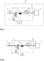
- Further details and features of the present invention and its embodiments shall now be described and explained in the figures.
- It is shown in:
- Fig. 1
- an embodiment of the air dryer unit according to the present invention in a schematical overview;
- Fig. 2
- another embodiment of the air dryer unit of the present invention in a schematical overview.
- Turning to
Fig. 1 , an embodiment of the air dryer unit is described. - In the embodiment, the air dryer system 1 is integrated into a utility vehicle 5.
- The air dryer unit 1 has a housing.
- The air dryer unit 1 has at least one compressed air inlet 6, in particular an inlet port.
- Also, the air dryer unit 1 has at least one compressed air outlet 7, in particular an outlet port.
- The air dryer unit 1 also has a main exhaust 15, in particular a main exhaust port.
- The air dryer unit 1 further has an exhaust valve 11.
- The exhaust valve 11 is a solenoid valve.
- In particular, the exhaust valve 11 is configured as a 3/2-way valve.
- In further embodiments, the exhaust valve 11 can be another type of electromechanically operated valve.
- Furthermore, the air dryer unit 1 has a desiccant unit 12.
- Also, the air dryer unit 1 has a main check valve 13.
- In addition to that, the air dryer unit 1 has a nozzle 14 or throttle 14.
- In one embodiment, the nozzle 14 can be integrated into the main check valve 13. Furthermore, the main check valve 13 and the nozzle 14 can be incorporated into a common unit, e.g., within one common housing.
- The air dryer unit 1 is connected to a compressor 2.
- The compressor 2 is connected at the compressed air inlet 6.
- In particular, a delivery line of the compressor 2 is connected to the compressed air inlet 6 directly with a flange or indirectly with a suitable piping.
- Also, the compressed air outlet 7 is connected to a compressed air system 3.
- The compressed air system 3 is integrated into the utility vehicle 5 and supplies different consumer systems with compressed air, such at the vehicle's brakes, a suspension and/or an auxiliary air system.
- Also, the compressed air system 3 can provide compressed air to connected external systems, such as an air system of a trailer.
- In the air dryer unit 1, the compressed air inlet 6 is connected with the desiccant unit 12.
- The desiccant unit 12 is provided with a desiccant material, which takes up humidity from air, which is flowing through the desiccant unit 12. In particular, moisture is removed from compressed air, as it is provided by the compressor 2 and received through the compressed air inlet 6.
- In further embodiments, the desiccant unit 12 can have a desiccant cartridge.
- Downstream from the desiccant 12, a main check valve 13 is arranged.
- Further downstream, the compressed air outlet 7 is provided, where the compressed air system 3 is connected.
- Thus, in a filling state of the system, compressed air is provided by the compressor 2, enters the air dryer unit 1 through the compressed air inlet 6, passes the desiccant unit 12, passes the main check valve 13 and reaches the compressed air system 3 through the compressed air outlet 7.
- The main check valve 13 ensures that air can only pass in a direction from the compressed air inlet 6 to the compressed air outlet 7.
- Furthermore, the nozzle 14 is provided in a
bypass line 8 in this embodiment. - The bypass line is configured to bypass the main check valve 13, i.e., it is connected upstream the main check valve 13 at one end and downstream the main check valve 13 at the other end.
- By providing the
bypass line 8 with the nozzle 14, a limited airflow can be allowed without passing the main check valve 13. In particular, a limited airflow from the compressed air outlet 7 to the desiccant unit 12 is possible. - The invention is based on the idea that different operational states of the air dryer unit 1 can be activated and an airflow within the air dryer unit 1 can be re-directed by switching an electrically controlled valve, instead of controlling a pilot valve or relay valve, which then provides a pneumatic control signal to another valve in order to change the air flow in the air dryer unit 1. Thus, no pilot valve is used to control the exhaust valve 11. Instead, an electrical control signal can directly switch the exhaust valve 11 and activate the different operational states of the air dryer unit 1, in particular a filling state and a regeneration state.
- This has the advantages that the system has fewer components, is lighter and smaller, and can be made more cost-efficient.
- The exhaust valve 11 is connected to the compressed air inlet 6, the desiccant unit 12 and the main exhaust 15.
- The control input of the exhaust valve is electrically connected to the control unit 10.
- In one position, in particular the resting position of the exhaust valve 11, it pneumatically connects the compressed air inlet 6 with the desiccant unit 12.
- In another position, in particular when the exhaust valve 11 is electrically activated, it pneumatically connects the main exhaust 15 with the desiccant unit 12.
- In the embodiment, a filling state and a regeneration state can be activated for the air dryer unit 1.
- In particular, the filling state and the regeneration state are operational states of the air dryer unit 1.
- The operational states are activated and/or switched by the control unit 10, which is configured to generate an electrical control signal and apply it to the exhaust valve's 11 control input.
- In the case, which is shown in
Fig. 1 , the fill state is activated. - In this case, the exhaust valve 11 is in its resting position, i.e., it connects the compressed air inlet 6 to the desiccant unit 12.
- When the compressor 2 provides compressed air, airflow is generated from the compressed air inlet 6 through the exhaust valve 11 to the desiccant unit 12.
- Since compressed air is provided from the side of the desiccant unit 12, the airflow can pass the main check valve 13 and reaches the compressed air system 3 via the compressed air outlet 7.
- The compressed air system 3 is thus filled with compressed air.
- When the control unit 10 generates a control signal to activate the regeneration state, the exhaust valve 11 is controlled such that it switches its position and connects the desiccant unit 12 to the main exhaust 15.
- Activation of the regeneration state can be triggered in different ways: For example, the regeneration state can be activated after a given time, where the air dryer unit 1 is operated in the filling state, depending on the volume of compressed air passing the desiccant unit 12 or depending on a humidity of the compressed air that is provided to the compressed air system 3.
- The connection between the desiccant unit 12 and the main exhaust 15 leads to a deaeration of the desiccant unit 12 and connected elements.
- In the regeneration state, the main check valve 13 prevents airflow back from the compressed air system 3 to the desiccant 12, but the nozzle 14 allows a certain amount of such airflow through the
bypass line 8. - The control unit 10 may also provide a control signal to stop the compressor 2, when the regeneration state is activated. In particular, this control system form the compressor 2 can be an electrical signal.
- At the end of the regeneration state, the control unit 10 generates a signal to activate the filling state again, and the exhaust valve 11 is controlled to switch again and connect the desiccant unit 12 to the compressed air inlet 6.
- The end of the regeneration state and/or the transition to the filling state can be triggered in different ways: For example, the regeneration state can be ended after a given time, where the air dryer unit 1 is operated in the regeneration state, depending on the volume of compressed air passing the desiccant unit 12 and leaving through the main exhaust 15.
- Turning to
Fig. 2 , another embodiment of the air dryer unit 1 is described. This embodiment is structurally very similar to the embodiment described with relation toFig. 1 . Wherefore, the same reference numerals have been used and the embodiment ofFig. 1 is explained in further detail by this embodiment. - In the case of
Fig. 2 , the air dryer unit 1 has a secondary check valve 16 arranged upstream from the exhaust valve 11, i.e. arranged between the compressed air inlet 6 and the exhaust valve 11. - When the filling state of the air dryer unit 1 is activated, pressurized air from the compressor 2 may pass the secondary check valve 16 and reach the desiccant unit 12 via the exhaust valve 11.
- The dried air then passes the main check valve 13 and is delivered to the compressed air system 3 through the compressed air outlet 7.
- When the system pressure reaches a certain level, the compressor 2 stops the air delivery, and the air dryer unit stays in a stand-by phase.
- Therein, the secondary check valve 16 prevents a backflow from the compressed air system 3 towards the compressor 2.
- The vehicle brake, a suspension system and auxiliary compressed air system can consume the pressurized air prepared by the air dryer unit 1 and provided to the compressed air system 3.
- If the system pressure drops below a certain level, the compressor 2 switches back to the filling phase, i.e., the compressor 2 pumps again pressurized air through the compressed air inlet 6.
- When desiccant material in the desiccant unit 12 should be regenerated, the position of the solenoid exhaust valve 11 is switched: The connection to the inlet line towards the compressed air inlet 6 is closed, and a connection from the desiccant unit 12 to the main exhaust 15 is opened.
- The dried air from downstream the desiccant unit 12 flows back from the compressed air system 3, expands on a regeneration nozzle 14, and cleans the desiccant unit 12 from the moisture and contamination.
- The regeneration air exits to the atmosphere at the main exhaust port 15.
-
- 1
- Air dryer unit
- 2
- Compressor
- 3
- Compressed air system
- 5
- Utility vehicle
- 6
- Compressed air inlet
- 7
- Compressed air outlet
- 8
- Bypass line
- 10
- Control unit
- 11
- Exhaust valve
- 12
- Desiccant unit
- 13
- Main check valve
- 14
- Throttle; nozzle
- 15
- Main exhaust
- 16
- Secondary check valve
Claims (10)
- Air dryer unit (1) for a utility vehicle (5), comprising a desiccant unit (12), which is arranged downstream from a compressed air inlet (6) and upstream from a compressed air outlet (7); and an exhaust valve (11), which is arranged between the compressed air inlet (6) and the desiccant unit (12); wherein the exhaust valve (11) is connected to a main exhaust (15); wherein the exhaust valve (11) is electromechanically operated.
- Air dryer unit (1) according to claim 1,
characterized in that
a main check valve (13) is arranged between the desiccant unit (12) and the compressed air outlet (7), and a throttle (14) is arranged in parallel to the main check valve (13) in a bypass air duct (8). - Air dryer unit (1) according to claim 1 or 2,
characterized in that
the air dryer unit (1) has two operational states, namely a filling state and a regeneration state, wherein in the filling state the exhaust valve (11) connects the desiccant unit (12) to the compressed air inlet (6), and in the regeneration state the exhaust valve (11) connects the desiccant unit (12) to the main exhaust (15). - Air dryer unit (1) according to one of the preceding claims,
characterized in that
the air dryer unit (1) further comprises a control unit (10), which is configured to output an electrical control signal, for directly controlling the exhaust valve (11). - Air dryer unit (1) according to one of the preceding claims,
characterized in that
the exhaust valve (11) is a solenoid valve. - Air dryer unit (1) according to one of the preceding claims,
characterized in that
the exhaust valve (11) is a 3/2-way valve. - Air dryer unit (1) according to one of the preceding claims,
characterized in that
the air dryer unit (1) further comprises a secondary check valve (16), which is arranged upstream from the desiccant unit (12), wherein the secondary check valve (16) is configured to prevent an air back-flow to the compressed air inlet. - Air dryer (1) unit according to one of the preceding claims,
characterized in that
the exhaust valve (11) is not controlled by another valve, in particular not by a pilot valve. - Method for operating an air dryer unit (1), wherein a control signal is received; and, depending on the control signal, a filling state or a regeneration state of the air dryer unit (1) is activated; wherein, when the filling state is activated, an exhaust valve (11) is controlled to connect a desiccant unit (12) to a compressed air inlet (6); and, when the regeneration state is activated, the exhaust valve (11) is controlled to connect the desiccant unit (12) to a main exhaust (15); wherein the control signal is an electrical signal and the exhaust valve (11) is controlled electromechanically.
- Method according to claim 9,
characterized in that
the air dryer unit (1) is an air dryer unit (1) according to one of claims 1 to 8.
Priority Applications (1)
| Application Number | Priority Date | Filing Date | Title |
|---|---|---|---|
| EP20206560.3A EP3995373B1 (en) | 2020-11-09 | 2020-11-09 | Air dryer with direct solenoid control |
Applications Claiming Priority (1)
| Application Number | Priority Date | Filing Date | Title |
|---|---|---|---|
| EP20206560.3A EP3995373B1 (en) | 2020-11-09 | 2020-11-09 | Air dryer with direct solenoid control |
Publications (2)
| Publication Number | Publication Date |
|---|---|
| EP3995373A1 true EP3995373A1 (en) | 2022-05-11 |
| EP3995373B1 EP3995373B1 (en) | 2025-01-08 |
Family
ID=73288381
Family Applications (1)
| Application Number | Title | Priority Date | Filing Date |
|---|---|---|---|
| EP20206560.3A Active EP3995373B1 (en) | 2020-11-09 | 2020-11-09 | Air dryer with direct solenoid control |
Country Status (1)
| Country | Link |
|---|---|
| EP (1) | EP3995373B1 (en) |
Cited By (2)
| Publication number | Priority date | Publication date | Assignee | Title |
|---|---|---|---|---|
| CN114834376A (en) * | 2022-06-08 | 2022-08-02 | 中国重汽集团济南动力有限公司 | Vehicle gas circuit control device and control method |
| CN116398407A (en) * | 2023-04-03 | 2023-07-07 | 宁波易力加运动科技有限公司 | Control method of air pump with desiccant reuse function |
Citations (5)
| Publication number | Priority date | Publication date | Assignee | Title |
|---|---|---|---|---|
| DE102007011256A1 (en) * | 2007-03-08 | 2008-09-11 | Knorr-Bremse Systeme für Nutzfahrzeuge GmbH | Compressed air supply device with improved regeneration capability |
| DE102008017361A1 (en) * | 2008-04-04 | 2009-10-08 | Knorr-Bremse Systeme für Nutzfahrzeuge GmbH | Compressed air supply device for controlling regeneration of air filter, has compressed air inlet for connecting compressor, where air filter is provided for processing compressed air for consumers |
| EP2743103A1 (en) * | 2010-12-16 | 2014-06-18 | WABCO GmbH | Air supply system and pneumatic system |
| DE102013007086A1 (en) * | 2013-04-24 | 2014-10-30 | Wabco Gmbh | Method for controlling the compressed air system of a motor vehicle externally filled with compressed air |
| US20190291707A1 (en) * | 2018-03-22 | 2019-09-26 | Hyundai Motor Company | Method of controlling air dryer using compressed air and heaterless air dryer thereof |
Family Cites Families (3)
| Publication number | Priority date | Publication date | Assignee | Title |
|---|---|---|---|---|
| DE3139682A1 (en) * | 1981-10-06 | 1983-05-05 | Robert Bosch Gmbh, 7000 Stuttgart | Air-drying device for compressed air system |
| DE19620851C2 (en) * | 1996-05-23 | 1999-12-09 | Knorr Bremse Systeme | Air conditioning arrangement for compressed air, in particular for pneumatic brake systems of motor vehicles |
| DE102005057003B4 (en) * | 2005-11-30 | 2007-09-13 | Knorr-Bremse Systeme für Nutzfahrzeuge GmbH | Compressed air supply system and method for operating a compressed air supply system |
-
2020
- 2020-11-09 EP EP20206560.3A patent/EP3995373B1/en active Active
Patent Citations (5)
| Publication number | Priority date | Publication date | Assignee | Title |
|---|---|---|---|---|
| DE102007011256A1 (en) * | 2007-03-08 | 2008-09-11 | Knorr-Bremse Systeme für Nutzfahrzeuge GmbH | Compressed air supply device with improved regeneration capability |
| DE102008017361A1 (en) * | 2008-04-04 | 2009-10-08 | Knorr-Bremse Systeme für Nutzfahrzeuge GmbH | Compressed air supply device for controlling regeneration of air filter, has compressed air inlet for connecting compressor, where air filter is provided for processing compressed air for consumers |
| EP2743103A1 (en) * | 2010-12-16 | 2014-06-18 | WABCO GmbH | Air supply system and pneumatic system |
| DE102013007086A1 (en) * | 2013-04-24 | 2014-10-30 | Wabco Gmbh | Method for controlling the compressed air system of a motor vehicle externally filled with compressed air |
| US20190291707A1 (en) * | 2018-03-22 | 2019-09-26 | Hyundai Motor Company | Method of controlling air dryer using compressed air and heaterless air dryer thereof |
Cited By (2)
| Publication number | Priority date | Publication date | Assignee | Title |
|---|---|---|---|---|
| CN114834376A (en) * | 2022-06-08 | 2022-08-02 | 中国重汽集团济南动力有限公司 | Vehicle gas circuit control device and control method |
| CN116398407A (en) * | 2023-04-03 | 2023-07-07 | 宁波易力加运动科技有限公司 | Control method of air pump with desiccant reuse function |
Also Published As
| Publication number | Publication date |
|---|---|
| EP3995373B1 (en) | 2025-01-08 |
Similar Documents
| Publication | Publication Date | Title |
|---|---|---|
| CN102770318B (en) | Compressed air preparation device for motor vehicles | |
| US8801111B2 (en) | Vehicle air braking system | |
| US6540308B1 (en) | Electronic compressed-air processing system | |
| US5678900A (en) | Unloader for a source of air under pressure on vehicles | |
| JP6403678B2 (en) | Compressed air supply device and method of operating compressed air supply device | |
| US9650029B2 (en) | Compressed air supply system and method for operating a compressed air supply system | |
| KR102011525B1 (en) | Compressed air processing system and method for operating a compressed air processing system | |
| US8544491B2 (en) | Compressed air supply system for a commercial vehicle, and method for operating a compressed air supply system | |
| EP3995373B1 (en) | Air dryer with direct solenoid control | |
| CN115899027A (en) | Dual Chamber Air Dryer and Pneumatic System | |
| JP2009023627A (en) | Compressed air supply system for vehicles | |
| CN108137028A (en) | Method and device for controlling an air drying unit of an air supply system for the primary and secondary air supply of a vehicle, in particular a rail vehicle | |
| KR101908752B1 (en) | Compressedair supply device for a utility vehicle and method for operating a compressedair supply device | |
| CN107206992B (en) | Device and method for supplying compressed air to a commercial vehicle | |
| JP2009078760A (en) | Compressed air supply system for vehicles | |
| US8616231B2 (en) | Valve device for a compressed air supply device and compressed air supply system | |
| JPH03246149A (en) | Pressure source for vehicle | |
| US6991001B2 (en) | Compressed air control apparatus for compressed air systems of motor vehicles | |
| US6050651A (en) | Vent valve and method of operation thereof | |
| JP2717803B2 (en) | Compressed air pressure source device | |
| CN112473329B (en) | Electric control compressed air drying equipment and control method thereof | |
| JP2002523286A (en) | Air dryer | |
| EP4736990A1 (en) | Vehicular air dryer system, air dryer, pneumatic vehicle system and vehicle | |
| JP2023019337A (en) | air brake system | |
| CN122057330A (en) | Automotive air dryers, pneumatic vehicle systems, vehicles, and methods for controlling pneumatic vehicle systems |
Legal Events
| Date | Code | Title | Description |
|---|---|---|---|
| PUAI | Public reference made under article 153(3) epc to a published international application that has entered the european phase |
Free format text: ORIGINAL CODE: 0009012 |
|
| STAA | Information on the status of an ep patent application or granted ep patent |
Free format text: STATUS: THE APPLICATION HAS BEEN PUBLISHED |
|
| AK | Designated contracting states |
Kind code of ref document: A1 Designated state(s): AL AT BE BG CH CY CZ DE DK EE ES FI FR GB GR HR HU IE IS IT LI LT LU LV MC MK MT NL NO PL PT RO RS SE SI SK SM TR |
|
| STAA | Information on the status of an ep patent application or granted ep patent |
Free format text: STATUS: REQUEST FOR EXAMINATION WAS MADE |
|
| 17P | Request for examination filed |
Effective date: 20220731 |
|
| RBV | Designated contracting states (corrected) |
Designated state(s): AL AT BE BG CH CY CZ DE DK EE ES FI FR GB GR HR HU IE IS IT LI LT LU LV MC MK MT NL NO PL PT RO RS SE SI SK SM TR |
|
| STAA | Information on the status of an ep patent application or granted ep patent |
Free format text: STATUS: EXAMINATION IS IN PROGRESS |
|
| 17Q | First examination report despatched |
Effective date: 20230814 |
|
| RAP3 | Party data changed (applicant data changed or rights of an application transferred) |
Owner name: KNORR-BREMSE SYSTEME FUER NUTZFAHRZEUGE GMBH |
|
| GRAP | Despatch of communication of intention to grant a patent |
Free format text: ORIGINAL CODE: EPIDOSNIGR1 |
|
| STAA | Information on the status of an ep patent application or granted ep patent |
Free format text: STATUS: GRANT OF PATENT IS INTENDED |
|
| INTG | Intention to grant announced |
Effective date: 20240926 |
|
| GRAS | Grant fee paid |
Free format text: ORIGINAL CODE: EPIDOSNIGR3 |
|
| GRAA | (expected) grant |
Free format text: ORIGINAL CODE: 0009210 |
|
| STAA | Information on the status of an ep patent application or granted ep patent |
Free format text: STATUS: THE PATENT HAS BEEN GRANTED |
|
| P01 | Opt-out of the competence of the unified patent court (upc) registered |
Free format text: CASE NUMBER: APP_59895/2024 Effective date: 20241105 |
|
| AK | Designated contracting states |
Kind code of ref document: B1 Designated state(s): AL AT BE BG CH CY CZ DE DK EE ES FI FR GB GR HR HU IE IS IT LI LT LU LV MC MK MT NL NO PL PT RO RS SE SI SK SM TR |
|
| REG | Reference to a national code |
Ref country code: GB Ref legal event code: FG4D |
|
| REG | Reference to a national code |
Ref country code: CH Ref legal event code: EP |
|
| REG | Reference to a national code |
Ref country code: DE Ref legal event code: R096 Ref document number: 602020044431 Country of ref document: DE |
|
| REG | Reference to a national code |
Ref country code: IE Ref legal event code: FG4D |
|
| REG | Reference to a national code |
Ref country code: LT Ref legal event code: MG9D |
|
| REG | Reference to a national code |
Ref country code: NL Ref legal event code: MP Effective date: 20250108 |
|
| REG | Reference to a national code |
Ref country code: AT Ref legal event code: MK05 Ref document number: 1758145 Country of ref document: AT Kind code of ref document: T Effective date: 20250108 |
|
| PG25 | Lapsed in a contracting state [announced via postgrant information from national office to epo] |
Ref country code: NL Free format text: LAPSE BECAUSE OF FAILURE TO SUBMIT A TRANSLATION OF THE DESCRIPTION OR TO PAY THE FEE WITHIN THE PRESCRIBED TIME-LIMIT Effective date: 20250108 |
|
| PG25 | Lapsed in a contracting state [announced via postgrant information from national office to epo] |
Ref country code: RS Free format text: LAPSE BECAUSE OF FAILURE TO SUBMIT A TRANSLATION OF THE DESCRIPTION OR TO PAY THE FEE WITHIN THE PRESCRIBED TIME-LIMIT Effective date: 20250408 |
|
| PG25 | Lapsed in a contracting state [announced via postgrant information from national office to epo] |
Ref country code: FI Free format text: LAPSE BECAUSE OF FAILURE TO SUBMIT A TRANSLATION OF THE DESCRIPTION OR TO PAY THE FEE WITHIN THE PRESCRIBED TIME-LIMIT Effective date: 20250108 |
|
| PG25 | Lapsed in a contracting state [announced via postgrant information from national office to epo] |
Ref country code: PL Free format text: LAPSE BECAUSE OF FAILURE TO SUBMIT A TRANSLATION OF THE DESCRIPTION OR TO PAY THE FEE WITHIN THE PRESCRIBED TIME-LIMIT Effective date: 20250108 |
|
| PG25 | Lapsed in a contracting state [announced via postgrant information from national office to epo] |
Ref country code: ES Free format text: LAPSE BECAUSE OF FAILURE TO SUBMIT A TRANSLATION OF THE DESCRIPTION OR TO PAY THE FEE WITHIN THE PRESCRIBED TIME-LIMIT Effective date: 20250108 |
|
| PG25 | Lapsed in a contracting state [announced via postgrant information from national office to epo] |
Ref country code: NO Free format text: LAPSE BECAUSE OF FAILURE TO SUBMIT A TRANSLATION OF THE DESCRIPTION OR TO PAY THE FEE WITHIN THE PRESCRIBED TIME-LIMIT Effective date: 20250408 Ref country code: IS Free format text: LAPSE BECAUSE OF FAILURE TO SUBMIT A TRANSLATION OF THE DESCRIPTION OR TO PAY THE FEE WITHIN THE PRESCRIBED TIME-LIMIT Effective date: 20250508 |
|
| PG25 | Lapsed in a contracting state [announced via postgrant information from national office to epo] |
Ref country code: HR Free format text: LAPSE BECAUSE OF FAILURE TO SUBMIT A TRANSLATION OF THE DESCRIPTION OR TO PAY THE FEE WITHIN THE PRESCRIBED TIME-LIMIT Effective date: 20250108 |
|
| PG25 | Lapsed in a contracting state [announced via postgrant information from national office to epo] |
Ref country code: PT Free format text: LAPSE BECAUSE OF FAILURE TO SUBMIT A TRANSLATION OF THE DESCRIPTION OR TO PAY THE FEE WITHIN THE PRESCRIBED TIME-LIMIT Effective date: 20250508 Ref country code: LV Free format text: LAPSE BECAUSE OF FAILURE TO SUBMIT A TRANSLATION OF THE DESCRIPTION OR TO PAY THE FEE WITHIN THE PRESCRIBED TIME-LIMIT Effective date: 20250108 |
|
| PG25 | Lapsed in a contracting state [announced via postgrant information from national office to epo] |
Ref country code: GR Free format text: LAPSE BECAUSE OF FAILURE TO SUBMIT A TRANSLATION OF THE DESCRIPTION OR TO PAY THE FEE WITHIN THE PRESCRIBED TIME-LIMIT Effective date: 20250409 Ref country code: BG Free format text: LAPSE BECAUSE OF FAILURE TO SUBMIT A TRANSLATION OF THE DESCRIPTION OR TO PAY THE FEE WITHIN THE PRESCRIBED TIME-LIMIT Effective date: 20250108 |
|
| PG25 | Lapsed in a contracting state [announced via postgrant information from national office to epo] |
Ref country code: AT Free format text: LAPSE BECAUSE OF FAILURE TO SUBMIT A TRANSLATION OF THE DESCRIPTION OR TO PAY THE FEE WITHIN THE PRESCRIBED TIME-LIMIT Effective date: 20250108 |
|
| PG25 | Lapsed in a contracting state [announced via postgrant information from national office to epo] |
Ref country code: SE Free format text: LAPSE BECAUSE OF FAILURE TO SUBMIT A TRANSLATION OF THE DESCRIPTION OR TO PAY THE FEE WITHIN THE PRESCRIBED TIME-LIMIT Effective date: 20250108 |
|
| PG25 | Lapsed in a contracting state [announced via postgrant information from national office to epo] |
Ref country code: SM Free format text: LAPSE BECAUSE OF FAILURE TO SUBMIT A TRANSLATION OF THE DESCRIPTION OR TO PAY THE FEE WITHIN THE PRESCRIBED TIME-LIMIT Effective date: 20250108 |
|
| REG | Reference to a national code |
Ref country code: DE Ref legal event code: R097 Ref document number: 602020044431 Country of ref document: DE |
|
| PG25 | Lapsed in a contracting state [announced via postgrant information from national office to epo] |
Ref country code: DK Free format text: LAPSE BECAUSE OF FAILURE TO SUBMIT A TRANSLATION OF THE DESCRIPTION OR TO PAY THE FEE WITHIN THE PRESCRIBED TIME-LIMIT Effective date: 20250108 |
|
| PG25 | Lapsed in a contracting state [announced via postgrant information from national office to epo] |
Ref country code: EE Free format text: LAPSE BECAUSE OF FAILURE TO SUBMIT A TRANSLATION OF THE DESCRIPTION OR TO PAY THE FEE WITHIN THE PRESCRIBED TIME-LIMIT Effective date: 20250108 Ref country code: CZ Free format text: LAPSE BECAUSE OF FAILURE TO SUBMIT A TRANSLATION OF THE DESCRIPTION OR TO PAY THE FEE WITHIN THE PRESCRIBED TIME-LIMIT Effective date: 20250108 |
|
| PG25 | Lapsed in a contracting state [announced via postgrant information from national office to epo] |
Ref country code: RO Free format text: LAPSE BECAUSE OF FAILURE TO SUBMIT A TRANSLATION OF THE DESCRIPTION OR TO PAY THE FEE WITHIN THE PRESCRIBED TIME-LIMIT Effective date: 20250108 |
|
| PG25 | Lapsed in a contracting state [announced via postgrant information from national office to epo] |
Ref country code: SK Free format text: LAPSE BECAUSE OF FAILURE TO SUBMIT A TRANSLATION OF THE DESCRIPTION OR TO PAY THE FEE WITHIN THE PRESCRIBED TIME-LIMIT Effective date: 20250108 |
|
| PLBE | No opposition filed within time limit |
Free format text: ORIGINAL CODE: 0009261 |
|
| STAA | Information on the status of an ep patent application or granted ep patent |
Free format text: STATUS: NO OPPOSITION FILED WITHIN TIME LIMIT |
|
| REG | Reference to a national code |
Ref country code: CH Ref legal event code: L10 Free format text: ST27 STATUS EVENT CODE: U-0-0-L10-L00 (AS PROVIDED BY THE NATIONAL OFFICE) Effective date: 20251119 |
|
| 26N | No opposition filed |
Effective date: 20251009 |
|
| PGFP | Annual fee paid to national office [announced via postgrant information from national office to epo] |
Ref country code: DE Payment date: 20251126 Year of fee payment: 6 |
|
| PG25 | Lapsed in a contracting state [announced via postgrant information from national office to epo] |
Ref country code: IT Free format text: LAPSE BECAUSE OF FAILURE TO SUBMIT A TRANSLATION OF THE DESCRIPTION OR TO PAY THE FEE WITHIN THE PRESCRIBED TIME-LIMIT Effective date: 20250108 |
|
| REG | Reference to a national code |
Ref country code: CH Ref legal event code: H13 Free format text: ST27 STATUS EVENT CODE: U-0-0-H10-H13 (AS PROVIDED BY THE NATIONAL OFFICE) Effective date: 20260623 |
|
| PG25 | Lapsed in a contracting state [announced via postgrant information from national office to epo] |
Ref country code: LT Free format text: LAPSE BECAUSE OF FAILURE TO SUBMIT A TRANSLATION OF THE DESCRIPTION OR TO PAY THE FEE WITHIN THE PRESCRIBED TIME-LIMIT Effective date: 20250108 |
|
| PG25 | Lapsed in a contracting state [announced via postgrant information from national office to epo] |
Ref country code: MC Free format text: LAPSE BECAUSE OF FAILURE TO SUBMIT A TRANSLATION OF THE DESCRIPTION OR TO PAY THE FEE WITHIN THE PRESCRIBED TIME-LIMIT Effective date: 20250108 |
|
| PG25 | Lapsed in a contracting state [announced via postgrant information from national office to epo] |
Ref country code: CH Free format text: LAPSE BECAUSE OF NON-PAYMENT OF DUE FEES Effective date: 20251130 Ref country code: LU Free format text: LAPSE BECAUSE OF NON-PAYMENT OF DUE FEES Effective date: 20251109 |