EP3995370A1 - A vehicle motion management system and a motion support system for a vehicle - Google Patents
A vehicle motion management system and a motion support system for a vehicle Download PDFInfo
- Publication number
- EP3995370A1 EP3995370A1 EP20205699.0A EP20205699A EP3995370A1 EP 3995370 A1 EP3995370 A1 EP 3995370A1 EP 20205699 A EP20205699 A EP 20205699A EP 3995370 A1 EP3995370 A1 EP 3995370A1
- Authority
- EP
- European Patent Office
- Prior art keywords
- vehicle
- wheel
- management system
- speed limit
- motion
- Prior art date
- Legal status (The legal status is an assumption and is not a legal conclusion. Google has not performed a legal analysis and makes no representation as to the accuracy of the status listed.)
- Pending
Links
- 230000005540 biological transmission Effects 0.000 claims description 13
- 238000000034 method Methods 0.000 claims description 9
- 238000004891 communication Methods 0.000 claims description 5
- 238000004590 computer program Methods 0.000 claims description 4
- 230000001133 acceleration Effects 0.000 description 11
- 239000010410 layer Substances 0.000 description 8
- 238000004364 calculation method Methods 0.000 description 5
- 230000008901 benefit Effects 0.000 description 4
- 230000000694 effects Effects 0.000 description 3
- 238000013459 approach Methods 0.000 description 1
- 230000007812 deficiency Effects 0.000 description 1
- 238000011161 development Methods 0.000 description 1
- 238000004146 energy storage Methods 0.000 description 1
- 239000002346 layers by function Substances 0.000 description 1
- 238000005259 measurement Methods 0.000 description 1
- 238000012986 modification Methods 0.000 description 1
- 230000004048 modification Effects 0.000 description 1
- 238000012544 monitoring process Methods 0.000 description 1
- 238000012545 processing Methods 0.000 description 1
- 230000001172 regenerating effect Effects 0.000 description 1
- 230000004044 response Effects 0.000 description 1
- 238000005096 rolling process Methods 0.000 description 1
- 239000000725 suspension Substances 0.000 description 1
- 230000001131 transforming effect Effects 0.000 description 1
- 210000003462 vein Anatomy 0.000 description 1
Images


Classifications
-
- B—PERFORMING OPERATIONS; TRANSPORTING
- B60—VEHICLES IN GENERAL
- B60T—VEHICLE BRAKE CONTROL SYSTEMS OR PARTS THEREOF; BRAKE CONTROL SYSTEMS OR PARTS THEREOF, IN GENERAL; ARRANGEMENT OF BRAKING ELEMENTS ON VEHICLES IN GENERAL; PORTABLE DEVICES FOR PREVENTING UNWANTED MOVEMENT OF VEHICLES; VEHICLE MODIFICATIONS TO FACILITATE COOLING OF BRAKES
- B60T8/00—Arrangements for adjusting wheel-braking force to meet varying vehicular or ground-surface conditions, e.g. limiting or varying distribution of braking force
- B60T8/17—Using electrical or electronic regulation means to control braking
- B60T8/176—Brake regulation specially adapted to prevent excessive wheel slip during vehicle deceleration, e.g. ABS
- B60T8/1761—Brake regulation specially adapted to prevent excessive wheel slip during vehicle deceleration, e.g. ABS responsive to wheel or brake dynamics, e.g. wheel slip, wheel acceleration or rate of change of brake fluid pressure
- B60T8/17616—Microprocessor-based systems
-
- B—PERFORMING OPERATIONS; TRANSPORTING
- B60—VEHICLES IN GENERAL
- B60W—CONJOINT CONTROL OF VEHICLE SUB-UNITS OF DIFFERENT TYPE OR DIFFERENT FUNCTION; CONTROL SYSTEMS SPECIALLY ADAPTED FOR HYBRID VEHICLES; ROAD VEHICLE DRIVE CONTROL SYSTEMS FOR PURPOSES NOT RELATED TO THE CONTROL OF A PARTICULAR SUB-UNIT
- B60W30/00—Purposes of road vehicle drive control systems not related to the control of a particular sub-unit, e.g. of systems using conjoint control of vehicle sub-units
- B60W30/18—Propelling the vehicle
- B60W30/18172—Preventing, or responsive to skidding of wheels
-
- B—PERFORMING OPERATIONS; TRANSPORTING
- B60—VEHICLES IN GENERAL
- B60L—PROPULSION OF ELECTRICALLY-PROPELLED VEHICLES; SUPPLYING ELECTRIC POWER FOR AUXILIARY EQUIPMENT OF ELECTRICALLY-PROPELLED VEHICLES; ELECTRODYNAMIC BRAKE SYSTEMS FOR VEHICLES IN GENERAL; MAGNETIC SUSPENSION OR LEVITATION FOR VEHICLES; MONITORING OPERATING VARIABLES OF ELECTRICALLY-PROPELLED VEHICLES; ELECTRIC SAFETY DEVICES FOR ELECTRICALLY-PROPELLED VEHICLES
- B60L15/00—Methods, circuits, or devices for controlling the traction-motor speed of electrically-propelled vehicles
- B60L15/20—Methods, circuits, or devices for controlling the traction-motor speed of electrically-propelled vehicles for control of the vehicle or its driving motor to achieve a desired performance, e.g. speed, torque, programmed variation of speed
-
- B—PERFORMING OPERATIONS; TRANSPORTING
- B60—VEHICLES IN GENERAL
- B60T—VEHICLE BRAKE CONTROL SYSTEMS OR PARTS THEREOF; BRAKE CONTROL SYSTEMS OR PARTS THEREOF, IN GENERAL; ARRANGEMENT OF BRAKING ELEMENTS ON VEHICLES IN GENERAL; PORTABLE DEVICES FOR PREVENTING UNWANTED MOVEMENT OF VEHICLES; VEHICLE MODIFICATIONS TO FACILITATE COOLING OF BRAKES
- B60T8/00—Arrangements for adjusting wheel-braking force to meet varying vehicular or ground-surface conditions, e.g. limiting or varying distribution of braking force
- B60T8/17—Using electrical or electronic regulation means to control braking
- B60T8/175—Brake regulation specially adapted to prevent excessive wheel spin during vehicle acceleration, e.g. for traction control
-
- B—PERFORMING OPERATIONS; TRANSPORTING
- B60—VEHICLES IN GENERAL
- B60W—CONJOINT CONTROL OF VEHICLE SUB-UNITS OF DIFFERENT TYPE OR DIFFERENT FUNCTION; CONTROL SYSTEMS SPECIALLY ADAPTED FOR HYBRID VEHICLES; ROAD VEHICLE DRIVE CONTROL SYSTEMS FOR PURPOSES NOT RELATED TO THE CONTROL OF A PARTICULAR SUB-UNIT
- B60W10/00—Conjoint control of vehicle sub-units of different type or different function
- B60W10/04—Conjoint control of vehicle sub-units of different type or different function including control of propulsion units
- B60W10/08—Conjoint control of vehicle sub-units of different type or different function including control of propulsion units including control of electric propulsion units, e.g. motors or generators
-
- B—PERFORMING OPERATIONS; TRANSPORTING
- B60—VEHICLES IN GENERAL
- B60W—CONJOINT CONTROL OF VEHICLE SUB-UNITS OF DIFFERENT TYPE OR DIFFERENT FUNCTION; CONTROL SYSTEMS SPECIALLY ADAPTED FOR HYBRID VEHICLES; ROAD VEHICLE DRIVE CONTROL SYSTEMS FOR PURPOSES NOT RELATED TO THE CONTROL OF A PARTICULAR SUB-UNIT
- B60W10/00—Conjoint control of vehicle sub-units of different type or different function
- B60W10/18—Conjoint control of vehicle sub-units of different type or different function including control of braking systems
- B60W10/184—Conjoint control of vehicle sub-units of different type or different function including control of braking systems with wheel brakes
-
- B—PERFORMING OPERATIONS; TRANSPORTING
- B60—VEHICLES IN GENERAL
- B60W—CONJOINT CONTROL OF VEHICLE SUB-UNITS OF DIFFERENT TYPE OR DIFFERENT FUNCTION; CONTROL SYSTEMS SPECIALLY ADAPTED FOR HYBRID VEHICLES; ROAD VEHICLE DRIVE CONTROL SYSTEMS FOR PURPOSES NOT RELATED TO THE CONTROL OF A PARTICULAR SUB-UNIT
- B60W40/00—Estimation or calculation of non-directly measurable driving parameters for road vehicle drive control systems not related to the control of a particular sub unit, e.g. by using mathematical models
- B60W40/10—Estimation or calculation of non-directly measurable driving parameters for road vehicle drive control systems not related to the control of a particular sub unit, e.g. by using mathematical models related to vehicle motion
- B60W40/101—Side slip angle of tyre
-
- B—PERFORMING OPERATIONS; TRANSPORTING
- B60—VEHICLES IN GENERAL
- B60W—CONJOINT CONTROL OF VEHICLE SUB-UNITS OF DIFFERENT TYPE OR DIFFERENT FUNCTION; CONTROL SYSTEMS SPECIALLY ADAPTED FOR HYBRID VEHICLES; ROAD VEHICLE DRIVE CONTROL SYSTEMS FOR PURPOSES NOT RELATED TO THE CONTROL OF A PARTICULAR SUB-UNIT
- B60W40/00—Estimation or calculation of non-directly measurable driving parameters for road vehicle drive control systems not related to the control of a particular sub unit, e.g. by using mathematical models
- B60W40/10—Estimation or calculation of non-directly measurable driving parameters for road vehicle drive control systems not related to the control of a particular sub unit, e.g. by using mathematical models related to vehicle motion
- B60W40/105—Speed
-
- B—PERFORMING OPERATIONS; TRANSPORTING
- B60—VEHICLES IN GENERAL
- B60W—CONJOINT CONTROL OF VEHICLE SUB-UNITS OF DIFFERENT TYPE OR DIFFERENT FUNCTION; CONTROL SYSTEMS SPECIALLY ADAPTED FOR HYBRID VEHICLES; ROAD VEHICLE DRIVE CONTROL SYSTEMS FOR PURPOSES NOT RELATED TO THE CONTROL OF A PARTICULAR SUB-UNIT
- B60W60/00—Drive control systems specially adapted for autonomous road vehicles
- B60W60/001—Planning or execution of driving tasks
-
- G—PHYSICS
- G06—COMPUTING; CALCULATING OR COUNTING
- G06F—ELECTRIC DIGITAL DATA PROCESSING
- G06F9/00—Arrangements for program control, e.g. control units
- G06F9/06—Arrangements for program control, e.g. control units using stored programs, i.e. using an internal store of processing equipment to receive or retain programs
- G06F9/30—Arrangements for executing machine instructions, e.g. instruction decode
- G06F9/30003—Arrangements for executing specific machine instructions
-
- B—PERFORMING OPERATIONS; TRANSPORTING
- B60—VEHICLES IN GENERAL
- B60L—PROPULSION OF ELECTRICALLY-PROPELLED VEHICLES; SUPPLYING ELECTRIC POWER FOR AUXILIARY EQUIPMENT OF ELECTRICALLY-PROPELLED VEHICLES; ELECTRODYNAMIC BRAKE SYSTEMS FOR VEHICLES IN GENERAL; MAGNETIC SUSPENSION OR LEVITATION FOR VEHICLES; MONITORING OPERATING VARIABLES OF ELECTRICALLY-PROPELLED VEHICLES; ELECTRIC SAFETY DEVICES FOR ELECTRICALLY-PROPELLED VEHICLES
- B60L2240/00—Control parameters of input or output; Target parameters
- B60L2240/40—Drive Train control parameters
- B60L2240/46—Drive Train control parameters related to wheels
- B60L2240/461—Speed
-
- B—PERFORMING OPERATIONS; TRANSPORTING
- B60—VEHICLES IN GENERAL
- B60L—PROPULSION OF ELECTRICALLY-PROPELLED VEHICLES; SUPPLYING ELECTRIC POWER FOR AUXILIARY EQUIPMENT OF ELECTRICALLY-PROPELLED VEHICLES; ELECTRODYNAMIC BRAKE SYSTEMS FOR VEHICLES IN GENERAL; MAGNETIC SUSPENSION OR LEVITATION FOR VEHICLES; MONITORING OPERATING VARIABLES OF ELECTRICALLY-PROPELLED VEHICLES; ELECTRIC SAFETY DEVICES FOR ELECTRICALLY-PROPELLED VEHICLES
- B60L2240/00—Control parameters of input or output; Target parameters
- B60L2240/40—Drive Train control parameters
- B60L2240/46—Drive Train control parameters related to wheels
- B60L2240/465—Slip
-
- B—PERFORMING OPERATIONS; TRANSPORTING
- B60—VEHICLES IN GENERAL
- B60L—PROPULSION OF ELECTRICALLY-PROPELLED VEHICLES; SUPPLYING ELECTRIC POWER FOR AUXILIARY EQUIPMENT OF ELECTRICALLY-PROPELLED VEHICLES; ELECTRODYNAMIC BRAKE SYSTEMS FOR VEHICLES IN GENERAL; MAGNETIC SUSPENSION OR LEVITATION FOR VEHICLES; MONITORING OPERATING VARIABLES OF ELECTRICALLY-PROPELLED VEHICLES; ELECTRIC SAFETY DEVICES FOR ELECTRICALLY-PROPELLED VEHICLES
- B60L2250/00—Driver interactions
- B60L2250/26—Driver interactions by pedal actuation
- B60L2250/28—Accelerator pedal thresholds
-
- B—PERFORMING OPERATIONS; TRANSPORTING
- B60—VEHICLES IN GENERAL
- B60W—CONJOINT CONTROL OF VEHICLE SUB-UNITS OF DIFFERENT TYPE OR DIFFERENT FUNCTION; CONTROL SYSTEMS SPECIALLY ADAPTED FOR HYBRID VEHICLES; ROAD VEHICLE DRIVE CONTROL SYSTEMS FOR PURPOSES NOT RELATED TO THE CONTROL OF A PARTICULAR SUB-UNIT
- B60W2300/00—Indexing codes relating to the type of vehicle
- B60W2300/12—Trucks; Load vehicles
-
- B—PERFORMING OPERATIONS; TRANSPORTING
- B60—VEHICLES IN GENERAL
- B60W—CONJOINT CONTROL OF VEHICLE SUB-UNITS OF DIFFERENT TYPE OR DIFFERENT FUNCTION; CONTROL SYSTEMS SPECIALLY ADAPTED FOR HYBRID VEHICLES; ROAD VEHICLE DRIVE CONTROL SYSTEMS FOR PURPOSES NOT RELATED TO THE CONTROL OF A PARTICULAR SUB-UNIT
- B60W2520/00—Input parameters relating to overall vehicle dynamics
- B60W2520/26—Wheel slip
-
- B—PERFORMING OPERATIONS; TRANSPORTING
- B60—VEHICLES IN GENERAL
- B60W—CONJOINT CONTROL OF VEHICLE SUB-UNITS OF DIFFERENT TYPE OR DIFFERENT FUNCTION; CONTROL SYSTEMS SPECIALLY ADAPTED FOR HYBRID VEHICLES; ROAD VEHICLE DRIVE CONTROL SYSTEMS FOR PURPOSES NOT RELATED TO THE CONTROL OF A PARTICULAR SUB-UNIT
- B60W2520/00—Input parameters relating to overall vehicle dynamics
- B60W2520/28—Wheel speed
-
- B—PERFORMING OPERATIONS; TRANSPORTING
- B60—VEHICLES IN GENERAL
- B60W—CONJOINT CONTROL OF VEHICLE SUB-UNITS OF DIFFERENT TYPE OR DIFFERENT FUNCTION; CONTROL SYSTEMS SPECIALLY ADAPTED FOR HYBRID VEHICLES; ROAD VEHICLE DRIVE CONTROL SYSTEMS FOR PURPOSES NOT RELATED TO THE CONTROL OF A PARTICULAR SUB-UNIT
- B60W2520/00—Input parameters relating to overall vehicle dynamics
- B60W2520/30—Wheel torque
-
- B—PERFORMING OPERATIONS; TRANSPORTING
- B60—VEHICLES IN GENERAL
- B60W—CONJOINT CONTROL OF VEHICLE SUB-UNITS OF DIFFERENT TYPE OR DIFFERENT FUNCTION; CONTROL SYSTEMS SPECIALLY ADAPTED FOR HYBRID VEHICLES; ROAD VEHICLE DRIVE CONTROL SYSTEMS FOR PURPOSES NOT RELATED TO THE CONTROL OF A PARTICULAR SUB-UNIT
- B60W2720/00—Output or target parameters relating to overall vehicle dynamics
- B60W2720/28—Wheel speed
-
- B—PERFORMING OPERATIONS; TRANSPORTING
- B60—VEHICLES IN GENERAL
- B60W—CONJOINT CONTROL OF VEHICLE SUB-UNITS OF DIFFERENT TYPE OR DIFFERENT FUNCTION; CONTROL SYSTEMS SPECIALLY ADAPTED FOR HYBRID VEHICLES; ROAD VEHICLE DRIVE CONTROL SYSTEMS FOR PURPOSES NOT RELATED TO THE CONTROL OF A PARTICULAR SUB-UNIT
- B60W2720/00—Output or target parameters relating to overall vehicle dynamics
- B60W2720/30—Wheel torque
-
- B—PERFORMING OPERATIONS; TRANSPORTING
- B60—VEHICLES IN GENERAL
- B60Y—INDEXING SCHEME RELATING TO ASPECTS CROSS-CUTTING VEHICLE TECHNOLOGY
- B60Y2200/00—Type of vehicle
- B60Y2200/90—Vehicles comprising electric prime movers
- B60Y2200/91—Electric vehicles
Definitions
- the present disclosure relates to a vehicle motion management system and a motion support system for a vehicle.
- the present disclosure also relates to a method as well as a control signal operable by the vehicle motion management system and the motion support system.
- the present disclosure is applicable to electrically propelled vehicles. Although the disclosure will mainly be directed to a vehicle in the form of a truck using electric machines for propulsion, it may also be applicable for other types of vehicles.
- control functionalities intend to improve the drivability of the vehicle, the comfort for the driver, and the safety during operation.
- WO 2017/215751 describes a wheel controller comprising a vehicle wheel capability module arranged in communication with a tire model generator.
- the vehicle wheel capability module is arranged to determine a longitudinal wheel force value based on a calculated wheel slip value.
- WO 2017/215751 provides significant advantages in e.g. overall vehicle dynamic control.
- WO 2017/215751 is still in need of further improvements for operating conditions where the wheel speed is relatively low, i.e. close to zero as low wheel speed will introduce inconsistencies when calculating wheel slip.
- WO 2017/215751 is still in need of further improvements for operating conditions where the wheel speed is relatively low, i.e. close to zero as low wheel speed will introduce inconsistencies when calculating wheel slip.
- a vehicle motion management system for a vehicle, the vehicle motion management system being connectable to a motion support system for communication of control signals therebetween, wherein the vehicle motion management system is configured to determine a desired torque for operating the vehicle at a current vehicle operating condition; determine a wheel slip limit for at least one wheel of the vehicle; determine, based at least on the wheel slip limit, a wheel speed limit for the at least one wheel of the vehicle; and transmit a control signal indicative of the desired torque and the wheel speed limit to the motion support system.
- the vehicle motion management system and the motion support system are control systems of the vehicle, where each of the control systems is arranged to execute various control functionalities for controlling operation of the vehicle, in particular for controlling wheel operations.
- the vehicle motion management system is preferably configured to receive, and to determine wheel parameters on a higher level, i.e. the vehicle motion management system determines a desired torque and wheel slip limit in a more generalized form, whereas the motion support system is arranged as a lower level control system configured to convert the parameters received from the vehicle motion management system to appropriate parameters for an actuator.
- the motion support system takes current driveline state(s) into account before forwarding an actuator signal to the actuator.
- the current driveline state may, for example, relate to a current vehicle transmission state, a gear stage for the vehicle transmission or a transmission clutch actuation state.
- the desired torque can, for example, be received from an operator of the vehicle pushing the accelerator pedal and/or pushing the brake pedal.
- the desired torque can also be received from a system autonomously controlling propulsion operation of the vehicle, or from an advanced driver assistance system (ADAS).
- ADAS advanced driver assistance system
- the wheel slip limit should be construed as a maximum allowable wheel slip for the at least one wheel during operation.
- Wheel slip is the relative longitudinal motion between the wheel of the vehicle and the ground surface thereof, i.e. the amount of "skidding".
- the wheel slip can be determined as a relationship between the longitudinal speed of the wheel and the rotational speed of the wheel taking the wheel radius into account.
- the wheel speed limit is based on the wheel speed relative to the road surface as seen in a wheel based coordinate system.
- the vehicle motion management system may be configured to determine a current rotational wheel speed and a current longitudinal wheel speed for at least one of the wheels of the vehicle; and determine a wheel slip for the at least one wheel based on the current rotational wheel speed and the current longitudinal wheel speed.
- the present disclosure is based on the insight that by transmitting a control signal indicative of a desired torque in combination with a wheel speed limit to the motion support system, the calculation of wheel slip limit can be executed by the higher level vehicle motion management system.
- the denominator in the wheel slip equation consists of the rotational wheel speed of the wheel. In low speed operation of the vehicle, the denominator is thus close to zero, or approaches zero which could result in a source of error when calculating wheel slip. Executing the wheel slip in the higher level vehicle motion management system is thus advantageous as potential inconsistencies in wheel slip calculation by separate motion support systems can be avoided. An improved wheel slip consistency is hereby achieved.
- transmitting a control signal indicative of the desired torque and the wheel speed limit to the motion support system is particularly advantageous when operating the vehicle using electric machines, as electric machines are able to be speed- and torque controlled.
- speed control can also be easier to achieve for e.g. service brakes, since rotation speed is a commonly used output of a tire torque balancing system and does not include any of the nonlinearities which is present in a wheel slip equation.
- the wheel speed limit may be further based on the desired torque.
- the desired torque i.e. a torque request
- the desired torque is used for calculating a slip limit which slip limit is used when calculating the wheel speed limit.
- the wheel speed limit may comprise an upper wheel speed limit and a lower wheel speed limit.
- the vehicle motion management system may be further configured to transmit the upper wheel speed limit to the motion support system at least when the desired torque is above zero; and transmit the lower wheel speed limit to the motion support system at least when the desired torque is below zero.
- An advantage is that different wheel speed limits can be used in dependence of vehicle acceleration or vehicle deceleration.
- the vehicle motion management system may be further configured to determine an offset wheel speed parameter; obtain a signal indicative of a wheel speed for the vehicle; and determine the wheel slip limit based on the offset wheel speed parameter when the wheel speed is below a threshold vehicle speed limit.
- the offset wheel speed parameter is advantageously used when the wheel speed is relatively low, such as close to zero. As described above, the wheel slip limit can be difficult to correctly calculate at low speeds due to the denominator of the wheel slip calculation model. Setting an offset wheel speed parameter thus advantageously remedies this potential inconsistency.
- the offset wheel speed parameter may be an upper offset wheel speed parameter and a lower offset wheel speed parameter, where the upper offset wheel speed parameter is higher than the current vehicle speed, and the lower offset wheel speed parameter is lower than the current vehicle speed.
- the offset wheel speed parameter can be obtained by using a tire model to map the offset wheel speed parameter to a desired torque.
- the wheel slip limit may be within a predetermined wheel slip range.
- the wheel of the vehicle will not be exposed to a too severe wheel slip or a too low wheel slip.
- the vehicle motion management system may be further configured to obtain a signal indicative of a current accelerator pedal position of an accelerator pedal of the vehicle; and determine the desired torque based on the current accelerator pedal position.
- the desired torque may instead be determined based on a signal received from an autonomous vehicle operating system.
- the vehicle motion management system may also be configured to obtain a signal indicative of a brake pedal position for determining the desired torque, or from a so-called retarder stalk position of a retarder of the vehicle.
- the vehicle motion management system can thus be arranged in an autonomously controlled vehicle as well as a driver controlled vehicle.
- the vehicle motion management system may be further configured to determine a wheel friction level between the at least one wheel and a road surface; and determine the current vehicle operating condition based on the determined wheel friction level.
- Other alternatives of determining the current vehicle operating condition For example, the current weight of the vehicle, i.e. the weight of a laden vehicle, the road topology at which the vehicle is current operated, etc. can also, as alternatives, or in conjunction with the wheel friction level, be used as input parameters when determining the current vehicle operating condition.
- a motion support system for a vehicle the motion support system being connectable to the above described vehicle motion management system and to at least one actuator configured to apply a torque to at least one wheel of the vehicle
- the motion support system is configured to receive a control signal from the vehicle motion management system, the control signal being indicative of a desired torque for operating the vehicle at a current vehicle operating condition, and indicative of a wheel speed limit for the at least one wheel of the vehicle; determine a current vehicle driveline state for the vehicle; determine, based on the current vehicle driveline state, the desired torque and the wheel speed limit, an operating torque and an actuator rotational speed limit; and transmit an actuator signal to the actuator for the actuator to generate the operating torque on the at least one wheel without exceeding the actuator rotational speed limit.
- the current driveline state should be construed as a current operating mode of the driveline, and in particular the transmission of the driveline.
- the current vehicle driveline state may be one of a current vehicle transmission state, a gear stage for the vehicle transmission or a transmission clutch actuation state.
- the motion support system is arranged as a lower level control system configured to convert the parameters received from the vehicle motion management system to appropriate parameters for an actuator taking the current driveline state into consideration.
- the wheel motion system may be a decentralized wheel motion system connectable to a wheel specific actuator configured to control a single wheel of the vehicle.
- the decentralized can be connected to a separate vehicle motion management system, or connected to a central vehicle motion management system, which central vehicle motion management system is connected to a plurality of decentralized wheel motion systems.
- a vehicle control system which comprises the vehicle motion management system as defined by any one of the embodiments of the first aspect, and a motion control system as defined by any one of the embodiments of the second aspect.
- a method for controlling an actuator of a vehicle comprising determining a desired torque for operating the vehicle at a current vehicle operating condition; determining a wheel slip limit for the at least one wheel of the vehicle; determining, based at least on the wheel slip limit, a wheel speed limit for the at least one wheel of the vehicle; determining an operating torque and an actuator rotational speed limit based on the desired torque, the wheel speed limit and a current vehicle driveline state; and controlling the actuator to generate the operating torque on the at least one wheel without exceeding the actuator rotational speed limit.
- a control signal representing instructions to be executed by a motion support system, the control signal comprising a torque component enabling the motion support system to determine an operating torque; and a wheel speed limit component representing wheel speed limit data which, when executed by the motion support system, cause the motion support system to generate an actuator signal corresponding to the operation torque subject to an actuator rotational speed limit, which is determinable based on the wheel speed limit component in view of a current vehicle driveline state.
- a computer program comprising program code means for performing the steps of the above described third aspect when the program is run on a computer.
- a computer readable medium carrying a computer program comprising program means for performing the steps of the above described third aspect when the program means is run on a computer.
- a vehicle 100 in the form of a truck.
- the vehicle comprises a plurality of wheels 102, wherein each of the wheels 102 comprises a respective actuator 104.
- each of the wheels 102 comprises a respective actuator 104.
- the embodiment depicted in Fig. 1 illustrates an actuator for each of the wheels 102, it should be readily understood that e.g. one pair of wheels 102 may be arranged without such an actuator 104.
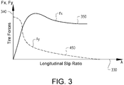
- the actuators 104 are preferably actuators for controlling a respective wheel propulsion device, such as an electric machine 106 arranged to e.g. provide a tire force to the wheel(s) of the vehicle 100, as depicted in Fig. 3 and described further below.
- Such an electric machine may thus be adapted to generate a propulsion torque as well as arranged in a regenerative braking mode for electrically charging a battery (not shown) or other energy storage system(s) of the vehicle 100.
- Electric machines may also generate braking torque without storing energy. For instance, brake resistors and the like may be used to dissipate the excess energy from the electric machines during braking.
- each of the actuators 104 is connected to a respective motion support system 300 arranged for controlling operation of the actuator 104.
- the motion support system 300 is preferably a decentralized motion support system 300, although centralized implementations are also possible. It is furthermore appreciated that some parts of the motion support system may be implemented no processing circuitry remote from the vehicle, such as on a remote server accessible from the vehicle via wireless link.
- each motion support system 300 is connected to a vehicle motion management system 200 of the vehicle 100 via a data bus communication arrangement 114 or the like. Hereby, control signals can be transmitted between the vehicle motion management system 200 and the motion support system 300.
- the vehicle motion management system 200 and the motion support system 300 will be described in further detail below with reference to Fig. 2 .
- the vehicle motion management system 200 as well as the motion support system 300 may include a microprocessor, microcontroller, programmable digital signal processor or another programmable device.
- the systems may also, or instead, include an application specific integrated circuit, a programmable gate array or programmable array logic, a programmable logic device, or a digital signal processor.
- the processor may further include computer executable code that controls operation of the programmable device.
- Fig. 2 is a schematic illustration of the vehicle motion management system 200 and the motion support system 300 according to an example embodiment.
- the vehicle motion management system 200 and the motion support system 300 thus form part of a vehicle motion system 500.
- the overall vehicle control system may be implemented on one or more vehicle unit computers (VUC).
- VUC vehicle unit computers
- the VUC may be configured to execute vehicle control methods which are organized according to a layered functional architecture where some functionality may be comprised in a traffic situation management (TSM) domain in a higher layer and some other functionality may be comprised in a vehicle motion management (VMM) domain residing in a lower functional layer.
- TSM traffic situation management
- VMM vehicle motion management
- Fig. 2 schematically illustrates functionality for controlling one or more wheels by some example motion support devices (MSDs), such as a friction brake and a propulsion device.
- the friction brake and the propulsion device are examples of wheel torque generating devices, which may also be referred to as actuators and which can be controlled by one or more motion support device control units.
- the control is based on, e.g., measurement data obtained from a wheel speed sensor and from other vehicle state sensors, such as radar sensors, lidar sensors, and vision based sensors such as camera sensors and infra-red detectors.
- Other example torque generating motion support devices which may be controlled according to the principles discussed herein comprise engine retarders and power steering devices.
- An MSD control unit may be arranged to control one or more actuators. For instance, it is not uncommon that an MSD control unit is arranged to control both wheel on a given axle.
- the TSM function plans driving operation with a time horizon of, e.g., 10 seconds or so. This time frame corresponds to, e.g., the time it takes for the vehicle to negotiate a curve.
- the vehicle maneuvers, planned and executed by the TSM can be associated with acceleration profiles and curvature profiles which describe a desired vehicle velocity and turning for a given maneuver.
- the TSM continuously requests the desired acceleration profiles areq and curvature profiles creq from the VMM function which performs force allocation to meet the requests from the TSM in a safe and robust manner.
- Acceleration profiles and curvature profiles may also be obtained from a driver of the heavy duty vehicle via normal control input devices such as a steering wheel, accelerator pedal and brake pedal.
- the VMM function operates with a time horizon of about 1 second or so, and continuously transforms the acceleration profiles a req and curvature profiles c req into control commands for controlling vehicle motion functions, actuated by the different MSDs of the vehicle 100 which report back capabilities to the VMM, which in turn are used as constraints in the vehicle control.
- the VMM function performs vehicle state or motion estimation, i.e., the VMM function continuously determines a vehicle state comprising positions, speeds, accelerations and articulation angles of the different units in the vehicle combination by monitoring operations using various sensors arranged on the vehicle 100, often but not always in connection to the MSDs.
- the result of the motion estimation i.e., the estimated vehicle state(s) may be input to a force generation module which determines the required global forces for the different vehicle units to cause the vehicle 100 to move according to the requested acceleration and curvature profiles a req , c req .
- the required global force vector is input to an MSD coordination function which allocates wheel forces and coordinates other MSDs such as steering and suspension.
- the coordinated MSDs then together provide the desired lateral Fy and longitudinal Fx forces on the vehicle units, as well as the required moments Mz, to obtain the desired motion by the vehicle combination.
- vehicle unit motion By determining vehicle unit motion using, e.g., global positioning systems, vision-based sensors, wheel speed sensors, radar sensors and/or lidar sensors, and translating this vehicle unit motion into a local coordinate system of a given wheel (in terms of, e.g., longitudinal and lateral velocity components), it becomes possible to accurately estimate wheel slip by comparing the vehicle unit motion in the wheel reference coordinate system to data obtained from the wheel speed sensor arranged in connection to the wheel.
- a local coordinate system of a given wheel in terms of, e.g., longitudinal and lateral velocity components
- a tyre model which will be discussed in more detail in connection to Fig. 3 below, can be used to translate between a desired longitudinal tire force Fx i and wheel slip.
- Wheel slip relates to a difference between wheel rotational velocity and speed over ground and will be discussed in more detail below.
- Wheel speed is a rotational speed of the wheel, given in units of, e.g., rotations per minute (rpm) or angular velocity in terms radians/second (rad/s) or degrees/second (deg/s).
- a tyre model is a model of wheel behavior which describes wheel force generated in longitudinal direction (in the rolling direction) and/or lateral direction (orthogonal to the longitudinal direction) as function of wheel slip.
- Hans Pacejka covers the fundamentals of tyre models. See, e.g., chapter 7 where the relationship between wheel slip and longitudinal force is discussed.
- the VMM function manages both force generation and MSD coordination, i.e., it determines what forces that are required at the vehicle units in order to fulfil the requests from the TSM function, for instance to accelerate the vehicle according to a requested acceleration profile requested by TSM and/or to generate a certain curvature motion by the vehicle also requested by TSM.
- the forces may comprise e.g., yaw moments Mz, longitudinal forces Fx and lateral forces Fy, as well as different types of torques to be applied at different wheels.
- the VMM is arranged as a higher layer control system, while the MSD is arranged as a lower layer control system.
- the higher layer VMM 200 is thus arranged to determine various parameters, as will be described below, in the vehicle/wheel domain, i.e. based on an overall vehicle condition, such as vehicle speed.
- the lower layer MSD 300 on the other hand is arranged to determine parameters which are specific for the actuator connected to the wheel. The lower layer MSD thus transform the signals received from the higher layer VMM into the actuator domain taking into account e.g. gear ratio, driveline inertia, etc.
- the vehicle motion management system 200 comprises a torque module 202, a wheel slip module 204 and a friction module 206.
- the vehicle motion management system 200 is further arranged to receive vehicle operation signal(s) 502 which comprises data operable by the vehicle motion management system 200 and its various modules 202, 204, 206.
- the vehicle operation signal(s) 502 provided to the vehicle motion management system 200 may, for example, comprises data in the form of signal(s) indicative of a current environment of the vehicle, a current traffic situation, vehicle weight parameter, such as e.g. if the vehicle is laden, unladen, partially laden, etc.
- the vehicle motion management system 200 may also receive other signals indicative of specific vehicle conditions, such as e.g.
- the torque module 202, the wheel slip module 204 and the friction module 206 are configured to transmit communication signals between one another, i.e. the different modules are configured to communicate with each other as will be evident by the following disclosure. It should be readily understood that the torque module 202, the wheel slip module 204 and the friction module 206 are illustrated as separate components merely for illustrative purposes.
- the vehicle motion management system 200 may of course also simply comprise various control functionalities itself which executes the below described functionalities.
- the vehicle motion management system 200 is arranged to receive an input signal with information relating to a current vehicle operating condition.
- the current vehicle operating condition may, for example, comprise data indicative of a wheel friction level between the wheel of the vehicle and the road surface, or the current weight of the vehicle, i.e. if the vehicle is unladen, laden or partially laden, or the topology of the road at which the vehicle is presently operating.
- the various operating conditions may thus be received by the vehicle motion management system 200 as individual components, or as a component using all different operating conditions as an overall vehicle operating condition.
- the different operating conditions for the vehicle can be determined using suitable sensor(s) and transmitted to the vehicle motion management system 200.
- the vehicle motion management system 200 further comprises the friction module 206.
- the vehicle motion management system 200 is arranged to, using the friction module 206, determine a wheel friction level between the at least one wheel and the road surface.
- the vehicle motion management system 200 can determine the current vehicle operating condition based on the determined wheel friction level.
- the torque module 202 is adapted to determine a desired torque for operating the vehicle at the current vehicle operating condition.
- the vehicle motion management system 200 determines a torque request, in the above described higher layer vehicle motion management system 200, for properly controlling the vehicle 100 at the current operating condition.
- the desired torque may, for example, be determined based on a current accelerator pedal position, a brake pedal position, or based on a signal received from an autonomous vehicle operating system.
- the wheel slip module 204 is arranged to determine a wheel slip limit for at least one wheel 102 of the vehicle 100. Thus, a maximum allowable wheel slip for the vehicle is determined, where the wheel of the vehicle is not allowed to exceed such wheel slip limit.
- the wheel slip limit can be determined by using e.g. the model 350 described below in relation to Fig. 3 .
- the vehicle motion management system 200 can hereby convert a force request into a slip request, whereby a slip limit is set based on the slip request.
- the slip limit can be set as a fixed value independently on the force request.
- the slip limit may also be based on a signal indicative of a current friction level between the road surface and the surface of the tire.
- the wheel slip module 204 is configured to determine a wheel speed limit for the at least one wheel.
- the vehicle motion management system 200 executes the wheel slip limit calculations and the wheel speed limit calculations.
- the wheel speed limit may also comprise an upper wheel speed limit and a lower wheel speed limit, where the upper wheel speed is used during acceleration, i.e. during propulsion, and the lower wheel speed limit is used during deceleration, i.e. during braking.
- the upper wheel speed limit is used when the wheel slip limit is positive and the desired torque is above zero, i.e. during acceleration, while the lower wheel speed limit is used when the wheel slip limit is negative and the desired torque is below zero, i.e. during deceleration.
- the wheel slip limit is within a predetermined range defined as: -1 ⁇ ⁇ lim ⁇ 1
- Fig. 3 illustrates a model 350 representing the relationship between the calculated longitudinal wheel slip and the estimated longitudinal wheel force values
- the model 450 represents the relationship between the maximum available lateral wheel forces for a given longitudinal wheel slip.
- the model 450 can also, for a predetermined lateral slip angle of the tire, represent the achieved lateral wheel force for a given longitudinal wheel slip.
- the vertical axis 340 represents the tire force generated between the surface supporting the wheel 102 and the wheel
- the horizontal axis 330 represents the longitudinal wheel slip of the wheel 102 as defined above in Eqn (1).
- the vehicle motion management system 200 transmits a control signal 550 to the motion support system 300, wherein the control signal is indicative of the desired torque and the wheel speed limit.
- the motion support system 300 in turn comprises a driveline state module 302 and an actuator torque module 304.
- the driveline state module 302 and the actuator torque module 304 are merely depicted as separate components for illustrative purposes.
- the motion support system 300 may of course also simply comprise various control functionalities itself which executes the below described functionalities.
- the motion support system 300 receives the control signal 550 from the vehicle motion management system 200.
- the driveline state module 302 determines a current driveline state for the vehicle 100.
- the current driveline state can, for example, relate to a current vehicle transmission state, a gear stage for the vehicle transmission, a transmission clutch actuation state, etc.
- the actuator torque module 304 is configured to determine an actuator specific torque, i.e. converts data of the desired torque from the vehicle motion management system 200 into data relevant for the actuator 104. In particular, the actuator torque module 304 determines an operating torque based on the desired torque received from the vehicle motion management system 200 as well as based on the current driveline state of the vehicle 100.
- the actuator torque module 304 also determines an actuator rotational speed limit for the actuator 104.
- the actuator rotational speed limit is based on the wheel speed limit received from the vehicle motion management system 200.
- the actuator rotational speed limit may also be based on the current driveline state.
- the motion support system 300 has converted the wheel speed limit received from the vehicle motion management system 200 to a wheel specific rotational wheel speed limit.
- the motion support system 300 thereafter transmits an actuator control signal 590 to the actuator 104 to generate the operating torque on the wheel 102 without exceeding the actuator rotational speed limit.
- a desired torque for operating the vehicle 100 at a current vehicle operating condition is determined S1.
- the desired torque may be determined based on an input signal from an accelerator pedal of the vehicle 100, or from an autonomous vehicle operating system, or from some advanced driver assistance system (ADAS) implemented in the vehicle 100.
- the current vehicle operating condition may comprise data indicative of a wheel friction level between the wheel of the vehicle and the road surface, the current weight of the vehicle, the topology of the road at which the vehicle is presently operating, and so on, as discussed above.
- a wheel slip limit is determined S2, and based on the determined wheel slip limit, a wheel speed limit for the at least one wheel 102 is determined S3. Based on the desired torque, the wheel speed limit and a current vehicle driveline state, an operating torque and an allowed actuator rotational speed range can be determined S4. Hereby, actuator specific parameters are determined.
- the actuator is controlled S5 to generate the operating torque on the at least one wheel 102 without exceeding the actuator rotational speed limit.
- torque control is allowed to generate the operating torque.
Landscapes
- Engineering & Computer Science (AREA)
- Transportation (AREA)
- Mechanical Engineering (AREA)
- Combustion & Propulsion (AREA)
- Chemical & Material Sciences (AREA)
- Automation & Control Theory (AREA)
- Physics & Mathematics (AREA)
- Theoretical Computer Science (AREA)
- Software Systems (AREA)
- Mathematical Physics (AREA)
- General Engineering & Computer Science (AREA)
- General Physics & Mathematics (AREA)
- Power Engineering (AREA)
- Human Computer Interaction (AREA)
- Microelectronics & Electronic Packaging (AREA)
- Fluid Mechanics (AREA)
- Control Of Driving Devices And Active Controlling Of Vehicle (AREA)
- Regulating Braking Force (AREA)
Abstract
Description
- The present disclosure relates to a vehicle motion management system and a motion support system for a vehicle. The present disclosure also relates to a method as well as a control signal operable by the vehicle motion management system and the motion support system. The present disclosure is applicable to electrically propelled vehicles. Although the disclosure will mainly be directed to a vehicle in the form of a truck using electric machines for propulsion, it may also be applicable for other types of vehicles.
- In the field of vehicle, in particularly low-, medium- and heavy-duty vehicles commonly referred to as trucks, there is a continuous development with regards to various control functionalities of the vehicle. In particular, the control functionalities intend to improve the drivability of the vehicle, the comfort for the driver, and the safety during operation.
- A system for improving, for example, the overall vehicle stability is described in
WO 2017/215751 . In particular,WO 2017/215751 describes a wheel controller comprising a vehicle wheel capability module arranged in communication with a tire model generator. The vehicle wheel capability module is arranged to determine a longitudinal wheel force value based on a calculated wheel slip value. - The system described by
WO 2017/215751 provides significant advantages in e.g. overall vehicle dynamic control. However,WO 2017/215751 is still in need of further improvements for operating conditions where the wheel speed is relatively low, i.e. close to zero as low wheel speed will introduce inconsistencies when calculating wheel slip. There is thus a desire to improve the controllability of a control system at least during low speed operation. - It is thus an object of the present disclosure to at least partially overcome the above described deficiencies.
- According to a first aspect, there is provided a vehicle motion management system for a vehicle, the vehicle motion management system being connectable to a motion support system for communication of control signals therebetween, wherein the vehicle motion management system is configured to determine a desired torque for operating the vehicle at a current vehicle operating condition; determine a wheel slip limit for at least one wheel of the vehicle; determine, based at least on the wheel slip limit, a wheel speed limit for the at least one wheel of the vehicle; and transmit a control signal indicative of the desired torque and the wheel speed limit to the motion support system.
- The vehicle motion management system and the motion support system are control systems of the vehicle, where each of the control systems is arranged to execute various control functionalities for controlling operation of the vehicle, in particular for controlling wheel operations. The vehicle motion management system is preferably configured to receive, and to determine wheel parameters on a higher level, i.e. the vehicle motion management system determines a desired torque and wheel slip limit in a more generalized form, whereas the motion support system is arranged as a lower level control system configured to convert the parameters received from the vehicle motion management system to appropriate parameters for an actuator. The motion support system takes current driveline state(s) into account before forwarding an actuator signal to the actuator. The current driveline state may, for example, relate to a current vehicle transmission state, a gear stage for the vehicle transmission or a transmission clutch actuation state.
- The desired torque can, for example, be received from an operator of the vehicle pushing the accelerator pedal and/or pushing the brake pedal. The desired torque can also be received from a system autonomously controlling propulsion operation of the vehicle, or from an advanced driver assistance system (ADAS).
- The wheel slip limit should be construed as a maximum allowable wheel slip for the at least one wheel during operation. Wheel slip is the relative longitudinal motion between the wheel of the vehicle and the ground surface thereof, i.e. the amount of "skidding". The wheel slip can be determined as a relationship between the longitudinal speed of the wheel and the rotational speed of the wheel taking the wheel radius into account. Accordingly, the wheel speed limit is based on the wheel speed relative to the road surface as seen in a wheel based coordinate system. According to an example embodiment, the vehicle motion management system may be configured to determine a current rotational wheel speed and a current longitudinal wheel speed for at least one of the wheels of the vehicle; and determine a wheel slip for the at least one wheel based on the current rotational wheel speed and the current longitudinal wheel speed.
- The present disclosure is based on the insight that by transmitting a control signal indicative of a desired torque in combination with a wheel speed limit to the motion support system, the calculation of wheel slip limit can be executed by the higher level vehicle motion management system. When calculating wheel slip, the denominator in the wheel slip equation consists of the rotational wheel speed of the wheel. In low speed operation of the vehicle, the denominator is thus close to zero, or approaches zero which could result in a source of error when calculating wheel slip. Executing the wheel slip in the higher level vehicle motion management system is thus advantageous as potential inconsistencies in wheel slip calculation by separate motion support systems can be avoided. An improved wheel slip consistency is hereby achieved.
- Furthermore, transmitting a control signal indicative of the desired torque and the wheel speed limit to the motion support system is particularly advantageous when operating the vehicle using electric machines, as electric machines are able to be speed- and torque controlled. As opposed to slip control, speed control can also be easier to achieve for e.g. service brakes, since rotation speed is a commonly used output of a tire torque balancing system and does not include any of the nonlinearities which is present in a wheel slip equation.
- According to an example embodiment, the wheel speed limit may be further based on the desired torque. Hereby, the desired torque, i.e. a torque request, is used for calculating a slip limit which slip limit is used when calculating the wheel speed limit.
- According to an example embodiment, the wheel speed limit may comprise an upper wheel speed limit and a lower wheel speed limit. The vehicle motion management system may be further configured to transmit the upper wheel speed limit to the motion support system at least when the desired torque is above zero; and transmit the lower wheel speed limit to the motion support system at least when the desired torque is below zero.
- An advantage is that different wheel speed limits can be used in dependence of vehicle acceleration or vehicle deceleration.
- According to an example embodiment, the vehicle motion management system may be further configured to determine an offset wheel speed parameter; obtain a signal indicative of a wheel speed for the vehicle; and determine the wheel slip limit based on the offset wheel speed parameter when the wheel speed is below a threshold vehicle speed limit.
- The offset wheel speed parameter is advantageously used when the wheel speed is relatively low, such as close to zero. As described above, the wheel slip limit can be difficult to correctly calculate at low speeds due to the denominator of the wheel slip calculation model. Setting an offset wheel speed parameter thus advantageously remedies this potential inconsistency. The offset wheel speed parameter may be an upper offset wheel speed parameter and a lower offset wheel speed parameter, where the upper offset wheel speed parameter is higher than the current vehicle speed, and the lower offset wheel speed parameter is lower than the current vehicle speed. The offset wheel speed parameter can be obtained by using a tire model to map the offset wheel speed parameter to a desired torque.
- According to an example embodiment, the wheel slip limit may be within a predetermined wheel slip range. Hereby, the wheel of the vehicle will not be exposed to a too severe wheel slip or a too low wheel slip.
- According to an example embodiment, the vehicle motion management system may be further configured to obtain a signal indicative of a current accelerator pedal position of an accelerator pedal of the vehicle; and determine the desired torque based on the current accelerator pedal position. However, and according to an example embodiment, the desired torque may instead be determined based on a signal received from an autonomous vehicle operating system. According to a further alternative as indicated above, the vehicle motion management system may also be configured to obtain a signal indicative of a brake pedal position for determining the desired torque, or from a so-called retarder stalk position of a retarder of the vehicle. The vehicle motion management system can thus be arranged in an autonomously controlled vehicle as well as a driver controlled vehicle.
- According to an example embodiment, the vehicle motion management system may be further configured to determine a wheel friction level between the at least one wheel and a road surface; and determine the current vehicle operating condition based on the determined wheel friction level. Other alternatives of determining the current vehicle operating condition. For example, the current weight of the vehicle, i.e. the weight of a laden vehicle, the road topology at which the vehicle is current operated, etc. can also, as alternatives, or in conjunction with the wheel friction level, be used as input parameters when determining the current vehicle operating condition.
- According to a second aspect, there is provided a motion support system for a vehicle, the motion support system being connectable to the above described vehicle motion management system and to at least one actuator configured to apply a torque to at least one wheel of the vehicle, wherein the motion support system is configured to receive a control signal from the vehicle motion management system, the control signal being indicative of a desired torque for operating the vehicle at a current vehicle operating condition, and indicative of a wheel speed limit for the at least one wheel of the vehicle; determine a current vehicle driveline state for the vehicle; determine, based on the current vehicle driveline state, the desired torque and the wheel speed limit, an operating torque and an actuator rotational speed limit; and transmit an actuator signal to the actuator for the actuator to generate the operating torque on the at least one wheel without exceeding the actuator rotational speed limit.
- The current driveline state should be construed as a current operating mode of the driveline, and in particular the transmission of the driveline. According to an example embodiment, the current vehicle driveline state may be one of a current vehicle transmission state, a gear stage for the vehicle transmission or a transmission clutch actuation state. Hereby, and as indicated above, the motion support system is arranged as a lower level control system configured to convert the parameters received from the vehicle motion management system to appropriate parameters for an actuator taking the current driveline state into consideration.
- According to an example embodiment, the wheel motion system may be a decentralized wheel motion system connectable to a wheel specific actuator configured to control a single wheel of the vehicle.
- Using a decentralized wheel motion system enables for rapid response to the specific actuator it is connected to, which hence improves the operational propulsion/braking performance of the vehicle. The decentralized can be connected to a separate vehicle motion management system, or connected to a central vehicle motion management system, which central vehicle motion management system is connected to a plurality of decentralized wheel motion systems.
- Further effects and features of the second aspect are largely analogous to those described above in relation to the first aspect. By means of the above described first and second aspects, a vehicle control system is thus provided which comprises the vehicle motion management system as defined by any one of the embodiments of the first aspect, and a motion control system as defined by any one of the embodiments of the second aspect.
- According to a third aspect, there is provided a method for controlling an actuator of a vehicle, the actuator being configured to apply a torque on at least one wheel of the vehicle, wherein the method comprises determining a desired torque for operating the vehicle at a current vehicle operating condition; determining a wheel slip limit for the at least one wheel of the vehicle; determining, based at least on the wheel slip limit, a wheel speed limit for the at least one wheel of the vehicle; determining an operating torque and an actuator rotational speed limit based on the desired torque, the wheel speed limit and a current vehicle driveline state; and controlling the actuator to generate the operating torque on the at least one wheel without exceeding the actuator rotational speed limit.
- Effects and features of the third aspect are largely analogous to those described above in relation to the first and second aspects. Thus, features described above in relation to the vehicle motion management system as well as the motion support system are applicable to the method described in the third aspect.
- According to a fourth aspect, there is provided a control signal representing instructions to be executed by a motion support system, the control signal comprising a torque component enabling the motion support system to determine an operating torque; and a wheel speed limit component representing wheel speed limit data which, when executed by the motion support system, cause the motion support system to generate an actuator signal corresponding to the operation torque subject to an actuator rotational speed limit, which is determinable based on the wheel speed limit component in view of a current vehicle driveline state.
- According to a fifth aspect, there is provided a computer program comprising program code means for performing the steps of the above described third aspect when the program is run on a computer.
- According to a sixth aspect, there is provided a computer readable medium carrying a computer program comprising program means for performing the steps of the above described third aspect when the program means is run on a computer.
- Effects and features of the fourth, fifth and sixth aspects are largely analogous to those described above in relation to the first and second aspects.
- Further features of, and advantages will become apparent when studying the appended claims and the following description. The skilled person will realize that different features may be combined to create embodiments other than those described in the following, without departing from the scope of the present disclosure.
- The above, as well as additional objects, features and advantages, will be better understood through the following illustrative and non-limiting detailed description of exemplary embodiments, wherein:
-
Fig. 1 is a lateral side view illustrating an example embodiment of a vehicle in the form of a truck; -
Fig. 2 is a schematic illustration of a vehicle motion management system and a motion support system according to an example embodiment; -
Fig. 3 is a graph illustrating an example embodiment of a model representing a relationship between wheel slip and tire forces; and -
Fig. 4 is a flow chart of a method for controlling an actuator of the vehicle inFig. 1 according to an example embodiment. - The present disclosure will now be described more fully hereinafter with reference to the accompanying drawings, in which exemplary embodiments are shown. The disclosure may, however, be embodied in many different forms and should not be construed as limited to the embodiments set forth herein; rather, these embodiments are provided for thoroughness and completeness. Like reference character refer to like elements throughout the description.
- With particular reference to
Fig. 1 , there is depicted avehicle 100 in the form of a truck. The vehicle comprises a plurality of wheels 102, wherein each of the wheels 102 comprises arespective actuator 104. Although the embodiment depicted inFig. 1 illustrates an actuator for each of the wheels 102, it should be readily understood that e.g. one pair of wheels 102 may be arranged without such anactuator 104. Further, theactuators 104 are preferably actuators for controlling a respective wheel propulsion device, such as anelectric machine 106 arranged to e.g. provide a tire force to the wheel(s) of thevehicle 100, as depicted inFig. 3 and described further below. Such an electric machine may thus be adapted to generate a propulsion torque as well as arranged in a regenerative braking mode for electrically charging a battery (not shown) or other energy storage system(s) of thevehicle 100. Electric machines may also generate braking torque without storing energy. For instance, brake resistors and the like may be used to dissipate the excess energy from the electric machines during braking. - Moreover, each of the
actuators 104 is connected to a respectivemotion support system 300 arranged for controlling operation of theactuator 104. Themotion support system 300 is preferably a decentralizedmotion support system 300, although centralized implementations are also possible. It is furthermore appreciated that some parts of the motion support system may be implemented no processing circuitry remote from the vehicle, such as on a remote server accessible from the vehicle via wireless link. Still further, eachmotion support system 300 is connected to a vehiclemotion management system 200 of thevehicle 100 via a databus communication arrangement 114 or the like. Hereby, control signals can be transmitted between the vehiclemotion management system 200 and themotion support system 300. The vehiclemotion management system 200 and themotion support system 300 will be described in further detail below with reference toFig. 2 . - The vehicle
motion management system 200 as well as themotion support system 300 may include a microprocessor, microcontroller, programmable digital signal processor or another programmable device. The systems may also, or instead, include an application specific integrated circuit, a programmable gate array or programmable array logic, a programmable logic device, or a digital signal processor. Where the system(s) include(s) a programmable device such as the microprocessor, microcontroller or programmable digital signal processor mentioned above, the processor may further include computer executable code that controls operation of the programmable device. - Turning to
Fig. 2 which is a schematic illustration of the vehiclemotion management system 200 and themotion support system 300 according to an example embodiment. The vehiclemotion management system 200 and themotion support system 300 thus form part of avehicle motion system 500. - The overall vehicle control system may be implemented on one or more vehicle unit computers (VUC). The VUC may be configured to execute vehicle control methods which are organized according to a layered functional architecture where some functionality may be comprised in a traffic situation management (TSM) domain in a higher layer and some other functionality may be comprised in a vehicle motion management (VMM) domain residing in a lower functional layer.
-
Fig. 2 schematically illustrates functionality for controlling one or more wheels by some example motion support devices (MSDs), such as a friction brake and a propulsion device. The friction brake and the propulsion device are examples of wheel torque generating devices, which may also be referred to as actuators and which can be controlled by one or more motion support device control units. The control is based on, e.g., measurement data obtained from a wheel speed sensor and from other vehicle state sensors, such as radar sensors, lidar sensors, and vision based sensors such as camera sensors and infra-red detectors. Other example torque generating motion support devices which may be controlled according to the principles discussed herein comprise engine retarders and power steering devices. An MSD control unit may be arranged to control one or more actuators. For instance, it is not uncommon that an MSD control unit is arranged to control both wheel on a given axle. - The TSM function plans driving operation with a time horizon of, e.g., 10 seconds or so. This time frame corresponds to, e.g., the time it takes for the vehicle to negotiate a curve. The vehicle maneuvers, planned and executed by the TSM, can be associated with acceleration profiles and curvature profiles which describe a desired vehicle velocity and turning for a given maneuver. The TSM continuously requests the desired acceleration profiles areq and curvature profiles creq from the VMM function which performs force allocation to meet the requests from the TSM in a safe and robust manner.
- Acceleration profiles and curvature profiles may also be obtained from a driver of the heavy duty vehicle via normal control input devices such as a steering wheel, accelerator pedal and brake pedal.
- The VMM function operates with a time horizon of about 1 second or so, and continuously transforms the acceleration profiles areq and curvature profiles creq into control commands for controlling vehicle motion functions, actuated by the different MSDs of the
vehicle 100 which report back capabilities to the VMM, which in turn are used as constraints in the vehicle control. The VMM function performs vehicle state or motion estimation, i.e., the VMM function continuously determines a vehicle state comprising positions, speeds, accelerations and articulation angles of the different units in the vehicle combination by monitoring operations using various sensors arranged on thevehicle 100, often but not always in connection to the MSDs. - The result of the motion estimation, i.e., the estimated vehicle state(s), may be input to a force generation module which determines the required global forces for the different vehicle units to cause the
vehicle 100 to move according to the requested acceleration and curvature profiles areq, creq. The required global force vector is input to an MSD coordination function which allocates wheel forces and coordinates other MSDs such as steering and suspension. The coordinated MSDs then together provide the desired lateral Fy and longitudinal Fx forces on the vehicle units, as well as the required moments Mz, to obtain the desired motion by the vehicle combination. - By determining vehicle unit motion using, e.g., global positioning systems, vision-based sensors, wheel speed sensors, radar sensors and/or lidar sensors, and translating this vehicle unit motion into a local coordinate system of a given wheel (in terms of, e.g., longitudinal and lateral velocity components), it becomes possible to accurately estimate wheel slip by comparing the vehicle unit motion in the wheel reference coordinate system to data obtained from the wheel speed sensor arranged in connection to the wheel.
- A tyre model, which will be discussed in more detail in connection to
Fig. 3 below, can be used to translate between a desired longitudinal tire force Fxi and wheel slip. Wheel slip relates to a difference between wheel rotational velocity and speed over ground and will be discussed in more detail below. Wheel speed is a rotational speed of the wheel, given in units of, e.g., rotations per minute (rpm) or angular velocity in terms radians/second (rad/s) or degrees/second (deg/s). - Herein, a tyre model is a model of wheel behavior which describes wheel force generated in longitudinal direction (in the rolling direction) and/or lateral direction (orthogonal to the longitudinal direction) as function of wheel slip. In "Tyre and vehicle dynamics", Elsevier Ltd. 2012, ISBN 978-0-08-097016-5, Hans Pacejka covers the fundamentals of tyre models. See, e.g., chapter 7 where the relationship between wheel slip and longitudinal force is discussed.
- To summarize, the VMM function manages both force generation and MSD coordination, i.e., it determines what forces that are required at the vehicle units in order to fulfil the requests from the TSM function, for instance to accelerate the vehicle according to a requested acceleration profile requested by TSM and/or to generate a certain curvature motion by the vehicle also requested by TSM. The forces may comprise e.g., yaw moments Mz, longitudinal forces Fx and lateral forces Fy, as well as different types of torques to be applied at different wheels.
- The VMM is arranged as a higher layer control system, while the MSD is arranged as a lower layer control system. The
higher layer VMM 200 is thus arranged to determine various parameters, as will be described below, in the vehicle/wheel domain, i.e. based on an overall vehicle condition, such as vehicle speed. Thelower layer MSD 300 on the other hand is arranged to determine parameters which are specific for the actuator connected to the wheel. The lower layer MSD thus transform the signals received from the higher layer VMM into the actuator domain taking into account e.g. gear ratio, driveline inertia, etc. - According to a non-limiting example, the vehicle
motion management system 200 comprises atorque module 202, awheel slip module 204 and afriction module 206. The vehiclemotion management system 200 is further arranged to receive vehicle operation signal(s) 502 which comprises data operable by the vehiclemotion management system 200 and itsvarious modules motion management system 200 may, for example, comprises data in the form of signal(s) indicative of a current environment of the vehicle, a current traffic situation, vehicle weight parameter, such as e.g. if the vehicle is laden, unladen, partially laden, etc. The vehiclemotion management system 200 may also receive other signals indicative of specific vehicle conditions, such as e.g. a current vehicle operating condition as will be described below. Thetorque module 202, thewheel slip module 204 and thefriction module 206 are configured to transmit communication signals between one another, i.e. the different modules are configured to communicate with each other as will be evident by the following disclosure. It should be readily understood that thetorque module 202, thewheel slip module 204 and thefriction module 206 are illustrated as separate components merely for illustrative purposes. The vehiclemotion management system 200 may of course also simply comprise various control functionalities itself which executes the below described functionalities. - The following will now describe the functional operation of the vehicle
motion management system 200. In particular, the vehiclemotion management system 200 is arranged to receive an input signal with information relating to a current vehicle operating condition. The current vehicle operating condition may, for example, comprise data indicative of a wheel friction level between the wheel of the vehicle and the road surface, or the current weight of the vehicle, i.e. if the vehicle is unladen, laden or partially laden, or the topology of the road at which the vehicle is presently operating. The various operating conditions may thus be received by the vehiclemotion management system 200 as individual components, or as a component using all different operating conditions as an overall vehicle operating condition. The different operating conditions for the vehicle can be determined using suitable sensor(s) and transmitted to the vehiclemotion management system 200. - As is described above, the vehicle
motion management system 200 further comprises thefriction module 206. According to an example embodiment, the vehiclemotion management system 200 is arranged to, using thefriction module 206, determine a wheel friction level between the at least one wheel and the road surface. The vehiclemotion management system 200 can determine the current vehicle operating condition based on the determined wheel friction level. - The
torque module 202 is adapted to determine a desired torque for operating the vehicle at the current vehicle operating condition. Hereby, the vehiclemotion management system 200 determines a torque request, in the above described higher layer vehiclemotion management system 200, for properly controlling thevehicle 100 at the current operating condition. - The desired torque may, for example, be determined based on a current accelerator pedal position, a brake pedal position, or based on a signal received from an autonomous vehicle operating system.
- The
wheel slip module 204 is arranged to determine a wheel slip limit for at least one wheel 102 of thevehicle 100. Thus, a maximum allowable wheel slip for the vehicle is determined, where the wheel of the vehicle is not allowed to exceed such wheel slip limit. Wheel slip can, as a non-limiting example, be determined based on below equation (1):
- A is the wheel slip for the wheel;
- ωw is the rotational velocity of the wheel;
- Rw is the wheel radius; and
- Vx,w is the longitudinal wheel speed of the wheel.
- The wheel slip limit can be determined by using e.g. the
model 350 described below in relation toFig. 3 . The vehiclemotion management system 200 can hereby convert a force request into a slip request, whereby a slip limit is set based on the slip request. According to another example, the slip limit can be set as a fixed value independently on the force request. The slip limit may also be based on a signal indicative of a current friction level between the road surface and the surface of the tire. - Based on the wheel slip limit, the
wheel slip module 204 is configured to determine a wheel speed limit for the at least one wheel. Hereby, the vehiclemotion management system 200 executes the wheel slip limit calculations and the wheel speed limit calculations. According to a non-limiting example, the wheel speed limit, ωw, sl, can be determined based on below equation (2):
- λlim is the wheel slip limit; and
- Treg is the desired torque.
- In the event the wheel speed is relatively low, i.e. close to zero, the vehicle
motion management system 200 can be arranged to determine a wheel slip based on an offset wheel speed parameter, whereby an offset wheel speed limit can be calculated according to the below non-limiting equation (3):
- ωw,ol is the wheel speed limit calculated from the speed offset limit;
- kοl,ω and ωol,max are gain and maximum speed offset parameters used for transforming the slip limit to an offset limit; and
- sgn(λ) is a signum function which equals 1 during acceleration, and -1 during deceleration.
- Moreover, the wheel speed limit may also comprise an upper wheel speed limit and a lower wheel speed limit, where the upper wheel speed is used during acceleration, i.e. during propulsion, and the lower wheel speed limit is used during deceleration, i.e. during braking. The upper wheel speed limit is used when the wheel slip limit is positive and the desired torque is above zero, i.e. during acceleration, while the lower wheel speed limit is used when the wheel slip limit is negative and the desired torque is below zero, i.e. during deceleration. Also, the wheel slip limit is within a predetermined range defined as:
-1 < λlim < 1 - The characteristics of the wheel slip relative to the longitudinal and transversal tire forces is depicted in
Fig. 3 . Thus,Fig. 3 illustrates amodel 350 representing the relationship between the calculated longitudinal wheel slip and the estimated longitudinal wheel force values, while themodel 450 represents the relationship between the maximum available lateral wheel forces for a given longitudinal wheel slip. Themodel 450 can also, for a predetermined lateral slip angle of the tire, represent the achieved lateral wheel force for a given longitudinal wheel slip. Thevertical axis 340 represents the tire force generated between the surface supporting the wheel 102 and the wheel, while thehorizontal axis 330 represents the longitudinal wheel slip of the wheel 102 as defined above in Eqn (1). - Referring back to
Fig. 2 , when the wheel speed limit and the desired torque have been determined, the vehiclemotion management system 200 transmits acontrol signal 550 to themotion support system 300, wherein the control signal is indicative of the desired torque and the wheel speed limit. - The
motion support system 300 in turn comprises adriveline state module 302 and anactuator torque module 304. In a similar vein as described above in relation to the vehiclemotion management system 200, thedriveline state module 302 and theactuator torque module 304 are merely depicted as separate components for illustrative purposes. Themotion support system 300 may of course also simply comprise various control functionalities itself which executes the below described functionalities. - As has been described above, the
motion support system 300 receives the control signal 550 from the vehiclemotion management system 200. Thedriveline state module 302 determines a current driveline state for thevehicle 100. The current driveline state can, for example, relate to a current vehicle transmission state, a gear stage for the vehicle transmission, a transmission clutch actuation state, etc. - The
actuator torque module 304 is configured to determine an actuator specific torque, i.e. converts data of the desired torque from the vehiclemotion management system 200 into data relevant for theactuator 104. In particular, theactuator torque module 304 determines an operating torque based on the desired torque received from the vehiclemotion management system 200 as well as based on the current driveline state of thevehicle 100. - The
actuator torque module 304, also determines an actuator rotational speed limit for theactuator 104. The actuator rotational speed limit is based on the wheel speed limit received from the vehiclemotion management system 200. The actuator rotational speed limit may also be based on the current driveline state. Hereby, themotion support system 300 has converted the wheel speed limit received from the vehiclemotion management system 200 to a wheel specific rotational wheel speed limit. - The
motion support system 300 thereafter transmits anactuator control signal 590 to theactuator 104 to generate the operating torque on the wheel 102 without exceeding the actuator rotational speed limit. - To sum up, reference is made to
Fig. 4 which shows a flow chart of a method for controlling theactuator 104 of thevehicle 100 according to an example embodiment. During operation of thevehicle 100, a desired torque for operating thevehicle 100 at a current vehicle operating condition is determined S1. As described above, the desired torque may be determined based on an input signal from an accelerator pedal of thevehicle 100, or from an autonomous vehicle operating system, or from some advanced driver assistance system (ADAS) implemented in thevehicle 100. The current vehicle operating condition may comprise data indicative of a wheel friction level between the wheel of the vehicle and the road surface, the current weight of the vehicle, the topology of the road at which the vehicle is presently operating, and so on, as discussed above. - Also, a wheel slip limit is determined S2, and based on the determined wheel slip limit, a wheel speed limit for the at least one wheel 102 is determined S3. Based on the desired torque, the wheel speed limit and a current vehicle driveline state, an operating torque and an allowed actuator rotational speed range can be determined S4. Hereby, actuator specific parameters are determined.
- Finally, the actuator is controlled S5 to generate the operating torque on the at least one wheel 102 without exceeding the actuator rotational speed limit. Thus, as long as the actuator rotational speed is kept within the allowable range, torque control is allowed to generate the operating torque.
- It is to be understood that the present disclosure is not limited to the embodiments described above and illustrated in the drawings; rather, the skilled person will recognize that many changes and modifications may be made within the scope of the appended claims.
Claims (16)
- A vehicle motion management system (200) for a vehicle, the vehicle motion management system being connectable to a motion support system (300) for communication of control signals therebetween, wherein the vehicle motion management system is configured to:- determine a desired torque for operating the vehicle at a current vehicle operating condition;- determine a wheel slip limit for at least one wheel of the vehicle;- determine, based at least on the wheel slip limit, a wheel speed limit for the at least one wheel of the vehicle; and- transmit a control signal indicative of the desired torque and the wheel speed limit to the motion support system (300).
- The vehicle motion management system (200) according to claim 1, wherein the wheel speed limit is further based on the desired torque.
- The vehicle motion management system (200) according to claim 2, wherein the wheel speed limit comprises an upper wheel speed limit and a lower wheel speed limit, the vehicle motion management system being configured to:- transmit the upper wheel speed limit to the motion support system (300) at least when the desired torque is above zero; and- transmit the lower wheel speed limit to the motion support system (300) at least when the desired torque is below zero.
- The vehicle motion management system (200) according to any one of the preceding claims, wherein the vehicle motion management system (200) is further configured to:- determine an offset wheel speed parameter;- obtain a signal indicative of a wheel speed for the vehicle; and- determine the wheel slip limit based on the offset wheel speed parameter when the wheel speed is below a threshold vehicle speed limit.
- The vehicle motion management system (200) according to any one of the preceding claims, wherein the vehicle motion management system (200) is further configured to:- determine a current rotational wheel speed and a current longitudinal wheel speed for at least one of the wheels of the vehicle; and- determine a wheel slip for the at least one wheel based on the current rotational wheel speed and the current longitudinal wheel speed.
- The vehicle motion management system (200) according to any one of the preceding claims, wherein the wheel slip limit is within a predetermined wheel slip range.
- The vehicle motion management system (200) according to any one of the preceding claims, wherein the vehicle motion management system (200) is further configured to:- obtain a signal indicative of a current accelerator pedal position of an accelerator pedal of the vehicle; and- determine the desired torque based on the current accelerator pedal position.
- The vehicle motion management system (200) according to any one of claims 1 - 6, wherein the desired torque is determined based on a signal received from an autonomous vehicle operating system.
- The vehicle motion management system (200) according to any one of the preceding claims, wherein the vehicle motion management system (200) is further configured to:- determine a wheel friction level between the at least one wheel and a road surface; and- determine the current vehicle operating condition based on the determined wheel friction level.
- A motion support system (300) for a vehicle, the motion support system (300) being connectable to a vehicle motion management system (200) and to at least one actuator configured to apply a torque to at least one wheel of the vehicle, wherein the motion support system (300) is configured to:- receive a control signal from the vehicle motion management system (200), the control signal being indicative of a desired torque for operating the vehicle at a current vehicle operating condition, and indicative of a wheel speed limit for the at least one wheel of the vehicle;- determine a current vehicle driveline state for the vehicle;- determine, based on the current vehicle driveline state, the desired torque and the wheel speed limit, an operating torque and an actuator rotational speed limit; and- transmit an actuator signal to the actuator (104) for the actuator to generate the operating torque on the at least one wheel without exceeding the actuator rotational speed limit.
- The motion support system (300) according to claim 10, wherein the current vehicle driveline state is one of a current vehicle transmission state, a gear stage for the vehicle transmission or a transmission clutch actuation state.
- The motion support system (300) according to any one of claims 10 or 11, wherein the wheel motion system (300) is a decentralized wheel motion system (300) connectable to a wheel specific actuator configured to control a single wheel of the vehicle.
- A method for controlling an actuator of a vehicle, the actuator being configured to apply a torque on at least one wheel (102) of the vehicle, wherein the method comprises:- determining (S1) a desired torque for operating the vehicle at a current vehicle operating condition;- determining (S2) a wheel slip limit for the at least one wheel of the vehicle;- determining (S3), based at least on the wheel slip limit, a wheel speed limit for the at least one wheel of the vehicle;- determining (S4) an operating torque and an actuator rotational speed limit based on the desired torque, the wheel speed limit and a current vehicle driveline state; and- controlling (S5) the actuator to generate the operating torque on the at least one wheel without exceeding the actuator rotational speed limit.
- A control signal representing instructions to be executed by a motion support system (300), the control signal comprising:- a torque component enabling the motion support system (300) to determine an operating torque; and- a wheel speed limit component representing wheel speed limit data which, when executed by the motion support system (300), cause the motion support system (300) to generate an actuator signal corresponding to the operation torque subject to an actuator rotational speed limit, which is determinable based on the wheel speed limit component in view of a current vehicle driveline state.
- A computer program comprising program code means for performing the steps of claim 13 when the program is run on a computer.
- A computer readable medium carrying a computer program comprising program means for performing the steps of claim 13 when the program means is run on a computer.
Priority Applications (11)
| Application Number | Priority Date | Filing Date | Title |
|---|---|---|---|
| EP20205699.0A EP3995370A1 (en) | 2020-11-04 | 2020-11-04 | A vehicle motion management system and a motion support system for a vehicle |
| KR1020227028074A KR20220125810A (en) | 2020-01-15 | 2020-12-04 | Vehicle motion management based on torque requests with speed limits |
| US17/758,679 US20230047444A1 (en) | 2020-01-15 | 2020-12-04 | Vehicle motion management based on torque request with speed limit |
| EP20816487.1A EP4090563A1 (en) | 2020-01-15 | 2020-12-04 | Vehicle motion management based on torque request with speed limit |
| CN202080093069.7A CN114945496A (en) | 2020-01-15 | 2020-12-04 | Vehicle motion management based on torque requests with speed limits |
| PCT/EP2020/084597 WO2021144065A1 (en) | 2020-01-15 | 2020-12-04 | Vehicle motion management based on torque request with speed limit |
| JP2022542395A JP7508563B2 (en) | 2020-01-15 | 2020-12-04 | Vehicle dynamics management based on torque demand with speed limit |
| US17/510,451 US20220135040A1 (en) | 2020-11-04 | 2021-10-26 | Vehicle motion management system and a motion support system for a vehicle |
| CN202111274096.7A CN114523971A (en) | 2020-11-04 | 2021-10-29 | Vehicle motion management system and motion support system for vehicle |
| JP2021179005A JP2022075585A (en) | 2020-11-04 | 2021-11-01 | Vehicle motion management system and motion support system for vehicle |
| KR1020210148574A KR20220060486A (en) | 2020-11-04 | 2021-11-02 | A vehicle motion management system and a motion support system for a vehicle |
Applications Claiming Priority (1)
| Application Number | Priority Date | Filing Date | Title |
|---|---|---|---|
| EP20205699.0A EP3995370A1 (en) | 2020-11-04 | 2020-11-04 | A vehicle motion management system and a motion support system for a vehicle |
Publications (1)
| Publication Number | Publication Date |
|---|---|
| EP3995370A1 true EP3995370A1 (en) | 2022-05-11 |
Family
ID=73059737
Family Applications (1)
| Application Number | Title | Priority Date | Filing Date |
|---|---|---|---|
| EP20205699.0A Pending EP3995370A1 (en) | 2020-01-15 | 2020-11-04 | A vehicle motion management system and a motion support system for a vehicle |
Country Status (5)
| Country | Link |
|---|---|
| US (1) | US20220135040A1 (en) |
| EP (1) | EP3995370A1 (en) |
| JP (1) | JP2022075585A (en) |
| KR (1) | KR20220060486A (en) |
| CN (1) | CN114523971A (en) |
Cited By (1)
| Publication number | Priority date | Publication date | Assignee | Title |
|---|---|---|---|---|
| WO2024120889A1 (en) | 2022-12-07 | 2024-06-13 | Zf Cv Systems Global Gmbh | Method for torque-based operation of an inverter of an electric drive of a vehicle, in particular a commercial vehicle, inverter, electric drive, vehicle, in particular commercial vehicle, computer program and/or computer-readable medium |
Families Citing this family (1)
| Publication number | Priority date | Publication date | Assignee | Title |
|---|---|---|---|---|
| EP4001030A1 (en) * | 2020-11-16 | 2022-05-25 | Volvo Truck Corporation | A method for controlling wheel slip of a vehicle |
Citations (4)
| Publication number | Priority date | Publication date | Assignee | Title |
|---|---|---|---|---|
| US5275474A (en) * | 1991-10-04 | 1994-01-04 | General Motors Corporation | Vehicle wheel slip control on split coefficient surface |
| WO2014184344A1 (en) * | 2013-05-16 | 2014-11-20 | Jaguar Land Rover Limited | Vehicle traction control |
| WO2017215751A1 (en) | 2016-06-15 | 2017-12-21 | Volvo Truck Corporation | A wheel controller for a vehicle |
| US20190322256A1 (en) * | 2017-01-21 | 2019-10-24 | Wabco Europe Bvba | Method for decelerating a trailer vehicle, wheel module for performing the method and vehicle combination having a wheel module of this type |
Family Cites Families (17)
| Publication number | Priority date | Publication date | Assignee | Title |
|---|---|---|---|---|
| JP2651937B2 (en) * | 1989-05-24 | 1997-09-10 | 株式会社豊田中央研究所 | Vehicle driving force control device |
| US6089681A (en) * | 1997-01-21 | 2000-07-18 | Denso Corporation | Antiskid control apparatus |
| US6542806B1 (en) * | 2001-05-24 | 2003-04-01 | Brunswick Corporation | Optimal tractive force control method for ground vehicles |
| US7192374B2 (en) * | 2004-06-14 | 2007-03-20 | Caterpillar Inc | System and method for controlling a continuously variable transmission |
| US7957881B2 (en) * | 2006-10-04 | 2011-06-07 | Toyota Jidosha Kabushiki Kaisha | Vehicle and method of controlling driving force for the vehicle based on detected slip of the drive wheel |
| SE533985C2 (en) * | 2009-06-11 | 2011-03-22 | Safe Mobility Ekonomisk Foerening | Method for controlling vehicle control and behavior |
| WO2011002348A1 (en) * | 2009-06-29 | 2011-01-06 | Volvo Lastvagnar Ab | A method and a system for changing a vehicle's trajectory |
| JP5252118B2 (en) * | 2010-03-02 | 2013-07-31 | トヨタ自動車株式会社 | Vehicle control device |
| GB2517995B (en) * | 2013-09-09 | 2018-04-11 | Jaguar Land Rover Ltd | Vehicle control system and method |
| GB2524060B (en) * | 2014-03-13 | 2016-12-14 | Jaguar Land Rover Ltd | Controller and method |
| US9238412B2 (en) * | 2014-03-18 | 2016-01-19 | GM Global Technology Operations LLC | Normalizing deceleration of a vehicle having a regenerative braking system |
| US9463697B1 (en) * | 2015-05-28 | 2016-10-11 | Atieva, Inc. | Dual data rate traction control system for a two wheel drive electric vehicle |
| EP3398825B1 (en) * | 2017-05-03 | 2020-03-11 | Volvo Car Corporation | Method and system for computing a road friction estimate |
| US10597028B2 (en) * | 2017-06-14 | 2020-03-24 | GM Global Technology Operations LLC | Systems and methods for holistic vehicle control with collaborative steering, electronic limited slip differential (ELSD), powertrain and braking |
| EP3694766B1 (en) * | 2017-10-10 | 2021-11-24 | Volvo Truck Corporation | Method for controlling a steering system of a vehicle |
| GB2577930B (en) * | 2018-10-11 | 2023-04-12 | Protean Electric Ltd | A traction control system |
| US11511790B2 (en) * | 2019-02-14 | 2022-11-29 | Steering Solutions Ip Holding Corporation | Road friction coefficient estimation using steering system signals |
-
2020
- 2020-11-04 EP EP20205699.0A patent/EP3995370A1/en active Pending
-
2021
- 2021-10-26 US US17/510,451 patent/US20220135040A1/en active Pending
- 2021-10-29 CN CN202111274096.7A patent/CN114523971A/en active Pending
- 2021-11-01 JP JP2021179005A patent/JP2022075585A/en active Pending
- 2021-11-02 KR KR1020210148574A patent/KR20220060486A/en unknown
Patent Citations (4)
| Publication number | Priority date | Publication date | Assignee | Title |
|---|---|---|---|---|
| US5275474A (en) * | 1991-10-04 | 1994-01-04 | General Motors Corporation | Vehicle wheel slip control on split coefficient surface |
| WO2014184344A1 (en) * | 2013-05-16 | 2014-11-20 | Jaguar Land Rover Limited | Vehicle traction control |
| WO2017215751A1 (en) | 2016-06-15 | 2017-12-21 | Volvo Truck Corporation | A wheel controller for a vehicle |
| US20190322256A1 (en) * | 2017-01-21 | 2019-10-24 | Wabco Europe Bvba | Method for decelerating a trailer vehicle, wheel module for performing the method and vehicle combination having a wheel module of this type |
Non-Patent Citations (1)
| Title |
|---|
| HANS PACEJKA: "Tyre and vehicle dynamics", 2012, ELSEVIER LTD |
Cited By (2)
| Publication number | Priority date | Publication date | Assignee | Title |
|---|---|---|---|---|
| WO2024120889A1 (en) | 2022-12-07 | 2024-06-13 | Zf Cv Systems Global Gmbh | Method for torque-based operation of an inverter of an electric drive of a vehicle, in particular a commercial vehicle, inverter, electric drive, vehicle, in particular commercial vehicle, computer program and/or computer-readable medium |
| DE102022132508A1 (en) | 2022-12-07 | 2024-06-13 | Zf Cv Systems Global Gmbh | Method for operating an inverter of an electric drive of a vehicle, in particular a commercial vehicle, inverter, electric drive, vehicle, computer program, computer-readable medium |
Also Published As
| Publication number | Publication date |
|---|---|
| US20220135040A1 (en) | 2022-05-05 |
| KR20220060486A (en) | 2022-05-11 |
| JP2022075585A (en) | 2022-05-18 |
| CN114523971A (en) | 2022-05-24 |
Similar Documents
| Publication | Publication Date | Title |
|---|---|---|
| EP3851345B1 (en) | Wheel slip based vehicle motion management for heavy duty vehicles | |
| US10597028B2 (en) | Systems and methods for holistic vehicle control with collaborative steering, electronic limited slip differential (ELSD), powertrain and braking | |
| US20230047444A1 (en) | Vehicle motion management based on torque request with speed limit | |
| EP3472008B1 (en) | A wheel controller for a vehicle | |
| US9145165B2 (en) | Drive controlling apparatus for a vehicle | |
| JP5970322B2 (en) | Vehicle motion control device | |
| US11794747B2 (en) | Method for controlling an actuator of a vehicle | |
| US20220135040A1 (en) | Vehicle motion management system and a motion support system for a vehicle | |
| JP2016182959A (en) | Motion control system of vehicle | |
| CN115715263A (en) | Steering control method and device | |
| JP2018030582A (en) | Motion control device of vehicle and motion control program | |
| CN116176529B (en) | Electromechanical braking system and vehicle | |
| JP2021109454A (en) | Turn control device of vehicle | |
| US11981214B2 (en) | Vehicle motion management system and an actuator control system for a vehicle | |
| JP2019142491A (en) | Vehicle motion control device | |
| CN116890770B (en) | Vehicle control system and method and vehicle | |
| US20240286615A1 (en) | A method for controlling propulsion of a heavy-duty vehicle | |
| WO2023169700A1 (en) | Selective free-rolling of wheels for robust vehicle speed over ground determination | |
| CN118119522A (en) | Reverse tire model enhancement function for heavy vehicles |
Legal Events
| Date | Code | Title | Description |
|---|---|---|---|
| PUAI | Public reference made under article 153(3) epc to a published international application that has entered the european phase |
Free format text: ORIGINAL CODE: 0009012 |
|
| STAA | Information on the status of an ep patent application or granted ep patent |
Free format text: STATUS: THE APPLICATION HAS BEEN PUBLISHED |
|
| AK | Designated contracting states |
Kind code of ref document: A1 Designated state(s): AL AT BE BG CH CY CZ DE DK EE ES FI FR GB GR HR HU IE IS IT LI LT LU LV MC MK MT NL NO PL PT RO RS SE SI SK SM TR |
|
| STAA | Information on the status of an ep patent application or granted ep patent |
Free format text: STATUS: REQUEST FOR EXAMINATION WAS MADE |
|
| 17P | Request for examination filed |
Effective date: 20221108 |
|
| RBV | Designated contracting states (corrected) |
Designated state(s): AL AT BE BG CH CY CZ DE DK EE ES FI FR GB GR HR HU IE IS IT LI LT LU LV MC MK MT NL NO PL PT RO RS SE SI SK SM TR |
|
| STAA | Information on the status of an ep patent application or granted ep patent |
Free format text: STATUS: EXAMINATION IS IN PROGRESS |
|
| 17Q | First examination report despatched |
Effective date: 20240422 |