EP3995234A1 - Oxidation-resistant alloy, and method for producing oxidation-resistant alloy - Google Patents
Oxidation-resistant alloy, and method for producing oxidation-resistant alloy Download PDFInfo
- Publication number
- EP3995234A1 EP3995234A1 EP21775074.4A EP21775074A EP3995234A1 EP 3995234 A1 EP3995234 A1 EP 3995234A1 EP 21775074 A EP21775074 A EP 21775074A EP 3995234 A1 EP3995234 A1 EP 3995234A1
- Authority
- EP
- European Patent Office
- Prior art keywords
- formed member
- powder
- compression forming
- alloy
- manufacturing
- Prior art date
- Legal status (The legal status is an assumption and is not a legal conclusion. Google has not performed a legal analysis and makes no representation as to the accuracy of the status listed.)
- Granted
Links
Images




Classifications
-
- B—PERFORMING OPERATIONS; TRANSPORTING
- B22—CASTING; POWDER METALLURGY
- B22F—WORKING METALLIC POWDER; MANUFACTURE OF ARTICLES FROM METALLIC POWDER; MAKING METALLIC POWDER; APPARATUS OR DEVICES SPECIALLY ADAPTED FOR METALLIC POWDER
- B22F7/00—Manufacture of composite layers, workpieces, or articles, comprising metallic powder, by sintering the powder, with or without compacting wherein at least one part is obtained by sintering or compression
- B22F7/06—Manufacture of composite layers, workpieces, or articles, comprising metallic powder, by sintering the powder, with or without compacting wherein at least one part is obtained by sintering or compression of composite workpieces or articles from parts, e.g. to form tipped tools
- B22F7/062—Manufacture of composite layers, workpieces, or articles, comprising metallic powder, by sintering the powder, with or without compacting wherein at least one part is obtained by sintering or compression of composite workpieces or articles from parts, e.g. to form tipped tools involving the connection or repairing of preformed parts
-
- B—PERFORMING OPERATIONS; TRANSPORTING
- B22—CASTING; POWDER METALLURGY
- B22F—WORKING METALLIC POWDER; MANUFACTURE OF ARTICLES FROM METALLIC POWDER; MAKING METALLIC POWDER; APPARATUS OR DEVICES SPECIALLY ADAPTED FOR METALLIC POWDER
- B22F3/00—Manufacture of workpieces or articles from metallic powder characterised by the manner of compacting or sintering; Apparatus specially adapted therefor ; Presses and furnaces
- B22F3/12—Both compacting and sintering
- B22F3/14—Both compacting and sintering simultaneously
- B22F3/15—Hot isostatic pressing
-
- B—PERFORMING OPERATIONS; TRANSPORTING
- B22—CASTING; POWDER METALLURGY
- B22F—WORKING METALLIC POWDER; MANUFACTURE OF ARTICLES FROM METALLIC POWDER; MAKING METALLIC POWDER; APPARATUS OR DEVICES SPECIALLY ADAPTED FOR METALLIC POWDER
- B22F3/00—Manufacture of workpieces or articles from metallic powder characterised by the manner of compacting or sintering; Apparatus specially adapted therefor ; Presses and furnaces
- B22F3/02—Compacting only
-
- B—PERFORMING OPERATIONS; TRANSPORTING
- B22—CASTING; POWDER METALLURGY
- B22F—WORKING METALLIC POWDER; MANUFACTURE OF ARTICLES FROM METALLIC POWDER; MAKING METALLIC POWDER; APPARATUS OR DEVICES SPECIALLY ADAPTED FOR METALLIC POWDER
- B22F3/00—Manufacture of workpieces or articles from metallic powder characterised by the manner of compacting or sintering; Apparatus specially adapted therefor ; Presses and furnaces
- B22F3/02—Compacting only
- B22F3/03—Press-moulding apparatus therefor
-
- B—PERFORMING OPERATIONS; TRANSPORTING
- B22—CASTING; POWDER METALLURGY
- B22F—WORKING METALLIC POWDER; MANUFACTURE OF ARTICLES FROM METALLIC POWDER; MAKING METALLIC POWDER; APPARATUS OR DEVICES SPECIALLY ADAPTED FOR METALLIC POWDER
- B22F3/00—Manufacture of workpieces or articles from metallic powder characterised by the manner of compacting or sintering; Apparatus specially adapted therefor ; Presses and furnaces
- B22F3/02—Compacting only
- B22F3/04—Compacting only by applying fluid pressure, e.g. by cold isostatic pressing [CIP]
-
- B—PERFORMING OPERATIONS; TRANSPORTING
- B22—CASTING; POWDER METALLURGY
- B22F—WORKING METALLIC POWDER; MANUFACTURE OF ARTICLES FROM METALLIC POWDER; MAKING METALLIC POWDER; APPARATUS OR DEVICES SPECIALLY ADAPTED FOR METALLIC POWDER
- B22F3/00—Manufacture of workpieces or articles from metallic powder characterised by the manner of compacting or sintering; Apparatus specially adapted therefor ; Presses and furnaces
- B22F3/10—Sintering only
- B22F3/105—Sintering only by using electric current other than for infrared radiant energy, laser radiation or plasma ; by ultrasonic bonding
- B22F2003/1051—Sintering only by using electric current other than for infrared radiant energy, laser radiation or plasma ; by ultrasonic bonding by electric discharge
-
- B—PERFORMING OPERATIONS; TRANSPORTING
- B22—CASTING; POWDER METALLURGY
- B22F—WORKING METALLIC POWDER; MANUFACTURE OF ARTICLES FROM METALLIC POWDER; MAKING METALLIC POWDER; APPARATUS OR DEVICES SPECIALLY ADAPTED FOR METALLIC POWDER
- B22F2207/00—Aspects of the compositions, gradients
- B22F2207/01—Composition gradients
- B22F2207/07—Particles with core-rim gradient
-
- B—PERFORMING OPERATIONS; TRANSPORTING
- B22—CASTING; POWDER METALLURGY
- B22F—WORKING METALLIC POWDER; MANUFACTURE OF ARTICLES FROM METALLIC POWDER; MAKING METALLIC POWDER; APPARATUS OR DEVICES SPECIALLY ADAPTED FOR METALLIC POWDER
- B22F2301/00—Metallic composition of the powder or its coating
- B22F2301/20—Refractory metals
-
- B—PERFORMING OPERATIONS; TRANSPORTING
- B22—CASTING; POWDER METALLURGY
- B22F—WORKING METALLIC POWDER; MANUFACTURE OF ARTICLES FROM METALLIC POWDER; MAKING METALLIC POWDER; APPARATUS OR DEVICES SPECIALLY ADAPTED FOR METALLIC POWDER
- B22F2998/00—Supplementary information concerning processes or compositions relating to powder metallurgy
- B22F2998/10—Processes characterised by the sequence of their steps
-
- B—PERFORMING OPERATIONS; TRANSPORTING
- B22—CASTING; POWDER METALLURGY
- B22F—WORKING METALLIC POWDER; MANUFACTURE OF ARTICLES FROM METALLIC POWDER; MAKING METALLIC POWDER; APPARATUS OR DEVICES SPECIALLY ADAPTED FOR METALLIC POWDER
- B22F2999/00—Aspects linked to processes or compositions used in powder metallurgy
Definitions
- the present invention relates to oxidation resistant alloy and a manufacturing method of oxidation resistant alloy.
- patent literature 1 discloses a method of manufacturing molybdenum alloy with oxidation resistance by adding boride silicide of molybdenum or molybdenum alloy.
- Patent literature 2 discloses a technology for forming a coating with molybdenum-silicon-boron (Mo-Si-B) based alloy through a plasma spraying method.
- Patent literature 3 discloses a technology for forming a coating with molybdenum-silicon-boron (Mo-Si-B) based alloy through sputtering.
- one objective is to provide oxidation resistant alloy.
- Other objectives would be understood from the following recitation and description of embodiments.
- a manufacture method of oxidation resistant alloy includes: producing a first formed member by applying compression forming to metal powder; and applying compression forming to the first formed member in a state in which the first formed member is covered with alloy powder different from the metal powder.
- the oxidation resistance of the major constituent of the alloy powder is higher than the oxidation resistance of the major constituent of the metal powder.
- oxidation resistant alloy includes: an inner structure that includes first metal as a main constituent; and an outer structure that includes an element that forms compound with the first metal, the outer structure covering the inner structure.
- the distribution of the element that forms the compound with the first metal is even in a thickness direction of the outer structure.
- the concentration of the compound of the first metal in the outer structure is different from the concentration of the compound of the first metal in the inner structure.
- the outer structure has a plurality of voids with aspect ratios of 1.3 or less.
- a manufacturing method 1 shown in FIG. 1 enables manufacture of oxidation resistant alloy with a reduced cost.
- a first formed member 100 is produced by applying compression forming to metal powder.
- the main constitute of the metal powder includes any metal, such as molybdenum (Mo), niobium (Nb), tungsten (W), metal-silicon-based alloy, metal-boron-based alloy, and the like.
- the metal contained in the metal-silicon-based alloy and the metal contained in the metal-boron-based alloy may include molybdenum (Mo), niobium (Nb), tungsten (W), or the like.
- Both the metal-silicon-based alloy and the metal-boron-based alloy may include metal-silicon-boron-based alloy.
- the metal-silicon-based alloy may include, for example, Mo 5 Si 3 , Mo 3 Si, or the like, and the metal-boron-based alloy may include, for example, MoB, Mo 2 B, or the like.
- the metal-silicon-boron-based alloy may include Mo 5 SiB 2 or the like.
- the main constitute of the powder may include material that has the highest concentration (e.g., the highest mass percentage) in the powder.
- the first formed member 100 may be produced by applying the compression forming to the metal powder without melting the metal powder.
- the first formed member 100 may be formed through cold isostatic pressing (CIP).
- the first formed member 100 may be formed through molding that achieves compression forming in one direction (e.g., the vertical direction) with a metal mold. This may result in that the first formed member 100 is formed as a non-sintered body, which is not yet sintered.
- oxidation resistant alloy 300 is produced by applying compression forming to the first formed member 100 in the state in which the first formed member 100 is covered with alloy powder.
- the alloy powder is different from the metal powder contained in the first formed member 100.
- the main constitute of the alloy powder includes oxidation resistant alloy, for example, metal-silicon-boron-based alloy.
- the metal contained in the metal-silicon-boron-based alloy may include molybdenum (Mo), niobium (Nb), tungsten (W), or the like, and the metal-silicon-boron-based alloy may include Mo 5 SiB 2 , Mo 5 Si 3 , Mo 3 Si, MoB, Mo 2 B, or the like.
- the main constitute of the alloy powder may exhibit higher oxidation resistance than the main constitute of the metal powder contained in the first formed member 100.
- the oxidation resistance may be measured as the thickness of the formed oxide from the surface or the decrease in the thickness of material (e.g., the amount of the thickness decrease of the material due to sublimation at the surface) when the material is placed in a space with a desired temperature (e.g., 1095 °C) for a desired time duration (e.g., two hours).
- the oxidation resistance is measured as higher as the thickness of the formed oxide is reduced or as the decrease in the thickness of the material is reduced.
- a second formed member 200 may be produced by implementing the compression forming without melting the alloy powder.
- the first formed member 100 is covered with the alloy powder.
- the first formed member 100 covered with the alloy powder is subjected to compression forming to produce the second formed member 200.
- the second formed member 200 includes an outer layer 210 that covers the first formed member 100 and is formed of the alloy powder.
- the first formed member 100 may be entirely covered with the alloy powder.
- the second formed member 200 may be produced through cold isostatic pressing or molding from the first formed member 100 covered with the alloy powder.
- the mold used in the compression forming of step S200 may be different from the mold used in the compression forming of step S100.
- Oxidation resistant alloy 300 may be produced by sintering the second formed member 200.
- the second formed member 200 may be sintered by any methods such as spark plasma sintering (SPS) and millimeter wave sintering.
- SPS spark plasma sintering
- the second formed member 200 may be sintered in a reducing atmosphere, for example, in hydrogen gas.
- the second formed member 200 is sintered, for example, after being detached from the mold used for the compressing forming.
- the second formed member 200 is detached from the mold used for the compressing forming and placed on a floor plate jig.
- the floor plate jig is formed of metal suitable for the main constituent of the alloy powder.
- the main constituent of the alloy powder is molybdenum compound, for example, the floor plate jig is formed of molybdenum or molybdenum compound.
- a support jig is placed depending on the shape of the second formed member 200. The support jig suppresses deformation of the second formed member 200 during the sintering, for example, deformation caused by gravity.
- the oxidation resistant alloy 300 includes an inner structure 310 and an outer structure 320.
- the inner structure 310 includes constituents corresponding to the constituents of the metal powder contained in the first formed member 100.
- the main constituent of the inner structure 310 is the same as a constituent of the first formed member 100.
- the outer structure 320 includes constituents corresponding to the constituents of the alloy powder that covered the first formed member 100.
- the main constituent of the outer structure 320 is the same as a constituent of the alloy powder that covered the first formed member 100.
- the surface of the oxidation resistant alloy 300 exhibits high oxidation resistance.
- the surface of the oxidation resistant alloy 300 is formed by the outer structure.
- the main constituent of the outer structure 320 includes oxidation resistant alloy that is the main constituent of the alloy powder. Accordingly, the oxidation resistant alloy 300 exhibits high oxidation resistance. Further, the oxidation resistant alloy 300 may also have ductility when the main constituent of the metal powder has ductility.
- the main constituent of the alloy (e.g., the main constituent of the outer structure 320) may include the material with the highest concentration (e.g., the highest mass percentage) in the alloy or include five materials with the highest five concentrations.
- the manufacturing cost can be reduced. If oxidation resistant alloy is manufactured with coating, the surface is cleaned before the coating. The coating process and the cleaning process increase the manufacture cost compared to the manufacturing method 1.
- the cleaning process may involve surface processing for covering the internal structure with alloy powder, for example, removal of a surface denaturation layer. The manufacturing method 1 allows omitting this cleaning process.
- the oxidation resistant alloy 300 can be manufactured to have a near net shape similar to the product shape, the manufacturing cost can be further reduced.
- the first formed member 100 may be covered with the alloy powder such that the distribution of an element(s) contained in the main constituent of the alloy powder is even.
- the distribution of the element(s) contained in the main constituent of the outer structure 320 of the oxidation resistant alloy 300 manufactured by this method may be even.
- the distribution of the element(s) contained in the main constituent of the outer structure 320 may be even in the thickness direction of the outer structure 320, not varying depending on the distance from the surface.
- the outer structure 320 may have a plurality of substantially spherical voids 322 with aspect ratios of, for example, 1.3 or less. For example, 80% or more of the voids 322 have aspect ratios of 1.3 or less.
- the inner structure 310 may also have a plurality of substantially spherical voids 312 with aspect ratios of, for example, 1.3 or less. For example, 80% or more of the voids 312 have aspect ratios of 1.3 or less.
- the density of the outer structure 320 may be 90% or more.
- the density of the inner structure 310 may also be 90% or more.
- the above-described structure may distinguish the oxidation resistant alloy 300 manufactured by the present method from alloy manufactured using a coating process.
- the even distribution may mean that the concentration of an element does not vary 10% or more.
- the concentration of an element may be measured by an electron probe micro analyzer (EPMA).
- EPMA electron probe micro analyzer
- element constituents are measured on a plurality of section surfaces of the inner structure 310 or the outer structure 320 with an electron probe micro analyzer.
- the element distributions may be measured in this way.
- the shapes of the voids 312 and 322, for example, the aspect ratios, may be measured by capturing images of section surfaces of the inner structure 310 and the outer structure 320.
- the main constituent of the alloy powder may include compound of the main constituent of the metal powder.
- the metal that forms the main constituent of the outer structure 320 may be the same as the metal that forms the main constituent of the inner structure 310. This enhances the coupling strength between the outer structure 320 and the inner structure 310.
- the compression forming and sintering may be simultaneously implemented.
- the oxidation resistant alloy 300 may be produced by applying compression forming to the first formed member 100 through hot isostatic pressing (HIP) in the state in which the first formed member 100 is covered with the alloy powder.
- HIP hot isostatic pressing
- a method shown in FIG. 5 may be implemented at step S200.
- piece members 220 are produced by applying compression forming to alloy powder.
- a piece member 220 has a plurality of contact surfaces 225 which may be placed in contact with the first formed member 100 and is configured such that the piece member 220 can be placed at a corner of the first formed member 100, in embodiments where the first formed member 100 is shaped as a cuboid, for example, at a vertex of the cuboid.
- the thickness L1 of the piece member 220 may be thinner than the thickness of the outer layer 210.
- the thickness L1 of the piece members 220 may be 90% or less of the thickness of the outer layer 210.
- the thickness L1 may be 80% or less of the thickness of the outer layer 210.
- the piece members 220 may be produced by implementing the compression forming without melting the alloy powder.
- the piece members 220 may be formed through cold isostatic pressing (CIP) or molding.
- the piece members 220 are placed to support the first formed member 100.
- the piece members 220 are placed at at least some of the corners of the first formed member 100.
- the piece members 220 may be placed at the vertices of the first formed member 100.
- the piece members 220 may be each placed at a boundary between two flat or curved surfaces, for example, along an edge of the cuboid.
- the oxidation resistant alloy 300 is produced by covering the first formed member 100 with alloy powder and applying compression forming to the first formed member 100 in the state in which the first formed member 100 is covered with the alloy powder.
- the first formed member 100 is covered with the alloy powder in the state in which the first formed member 100 is supported by the piece members 220.
- the first formed member 100 covered with the alloy powder is subjected to compression forming.
- a second formed member 200 may be produced by implementing the compression forming without melting the alloy powder.
- the first formed member 100 is covered with the piece members 220, which are formed of the alloy powder, and the outer layer 210.
- the second formed member 200 may be produced through cold isostatic pressing or molding.
- the oxidation resistant alloy 300 is then produced by sintering the second formed member 200 with a desired method.
- the piece members 220 may be used to manufacture the oxidation resistant alloy 300.
- the outer structure 320 of the oxidization resistant alloy 300 may have an even thickness. This manufacturing method can reduce exposure of the inner structure 310 of the oxidation resistant alloy 300 onto the surface of the oxidation resistant alloy 300.
- the compression forming and the sintering may be simultaneously implemented.
- compression forming of the first formed member 100 covered with the alloy powder may be achieved through hot isostatic pressing.
- a method shown in FIG. 10 may be implemented at step S200.
- a second formed member 200 is produced by applying compression forming to the first formed member 100 in the state in which the first formed member 100 is covered with the alloy powder.
- the first formed member 100 is covered with the alloy powder.
- the second formed member 200 is produced by applying compression forming to the first formed member 100 covered with the alloy powder.
- the second formed member 200 may be produced by implementing the compression forming without melting the alloy powder.
- the second formed member 200 may be produced from the first formed member 100 covered with the alloy powder through cold isostatic pressing or molding.
- oxidation resistant alloy 300 is produced by applying compression forming to the second formed member 200 in the state in which the second formed member 200 is covered with oxide powder.
- the second formed member 200 is covered with the oxide powder.
- the oxide powder may include, for example, part of aluminum oxide (Al 2 O 3 ), yttrium oxide (Y 2 O 3 ), chromium oxide (Cr 2 O 3 ), zirconia (ZrO 2 ), yttrium-stabilized zirconia (YSZ), magnesium oxide (MgO), and hafnium oxide (HfO 2 ).
- a third formed member 250 may be produced by implementing the compression forming without melting the oxide powder.
- the first formed member 100 is covered with an outer layer 210 formed of alloy powder.
- the second formed member 200 for example, the outer layer 210 is covered with an oxide layer 260 formed of the oxide powder.
- the second formed member 200 may be entirely covered with the oxide powder.
- the third formed member 250 may be produced through cold isostatic pressing or molding. Oxidation resistant alloy 300 is then produced by sintering the third formed member 250 with a desired method.
- the oxidation resistant alloy 300 thus manufactured includes an inner structure 310, an outer structure 320, and a surface layer 330. Since the surface layer 330 is formed of oxide, the oxidation resistant alloy 300 exhibits high oxidation resistance.
- the inner structure 310 and the outer structure 320 are formed in the same way as those of the oxidation resistant alloy 300 shown in FIG. 3 , and therefore no description is given here of the inner structure 310 and the outer structure 320. Further, since the oxidation resistant alloy 300 can be manufactured with a single sintering process, the manufacturing cost is reduced.
- the compression forming and the sintering may be simultaneously implemented.
- compression forming of the second formed member 200 covered with the oxide powder may be achieved through hot isostatic pressing.
- a process shown in FIG. 10 may be performed in step S230 shown in FIG. 5 .
- the first formed member 100 is covered with alloy powder in the state in which the first formed member 100 is supported by the piece members 220, and the first formed member 100 covered with the alloy powder is subjected to compression forming to produce the second formed member 200.
- the subsequent process is the same as that of embodiment 3, and therefore no description of the subsequent process is given here.
- a process shown in FIG. 13 may be implemented at step S260 shown in FIG. 10 .
- surface piece members 420 are formed by applying compression forming to oxide powder.
- a surface pixel member 420 has a plurality of contact surfaces 425 that may be placed in contact with the second formed member 200 and is configured such that the surface piece member 420 can be placed at a corner of the second formed member 200.
- the thickness L2 of the surface piece member 420 may be thinner than the thickness of the oxidation layer 260.
- the thickness L2 of the surface piece member 420 may be 90% or less of the thickness of the oxide layer 260.
- the thickness L2 may be 80% or less of the thickness of the oxide layer 260.
- the surface piece members 420 may be produced by implementing the compression forming without melting the oxide powder.
- the surface piece members 420 may be formed through cold isostatic pressing (CIP) or molding.
- the surface piece members 420 are placed to support the second formed member 200.
- the surface piece members 420 are placed at at least some of the corners of the second formed member 200.
- the surface piece members 420 may be placed at the vertices of the second formed member 200.
- oxidation resistant alloy 300 is produced by covering the second formed member 200 with oxide powder and applying compression forming to the second formed member 200 covered with the oxide powder.
- the second formed member 200 is covered with the oxide powder in the state in which the second formed member 200 is supported by the surface piece members 420.
- the second formed member 200 covered with the oxide powder is subjected to compression forming.
- a third formed member 250 may be produced by implementing compression forming without melting the oxide powder.
- the second formed member 200 is covered with surface piece members 420 and oxide powder, where the surface piece members 420 are formed of oxide powder.
- the third formed member 250 may be produced through cold isostatic pressing or molding. Oxidation resistant alloy 300 may be then produced by sintering the third formed member 250 with a desired method.
- the oxidation resistant alloy 300 may be manufactured using the surface piece members 420.
- the surface layer 330 of the oxidation resistant alloy 300 may have an even thickness. This manufacturing method can reduce exposure of the outer structure 320 and the inner structure 310 of the oxidation resistant alloy 300 onto the surface of the oxidation resistant alloy 300.
- the compression forming and the sintering may be simultaneously implemented.
- compression forming of the second formed member 200 covered with the oxide powder may be achieved by hot isostatic pressing.
- the oxidization resistant alloy 300 may be manufactured in any shapes achievable with compression forming.
- the oxidation resistant alloy 300 may be manufactured in a conical shape.
- piece members 220 may be disposed at the vertex of the cone and along the edge between the base and the side surface.
- the oxidation resistant alloy 300 may include a multi-layered outer structure 320.
- the outer structure 320 may be configured such that the closer the layers are to the surface of the oxidation resistant alloy 300, the higher oxidation resistances the layers exhibit.
- Such oxidation resistant alloy 300 may be manufactured by repeating step S200 of FIG. 1 .
- the sintering process may be performed after all the layers are formed through compression forming.
- the respective layers are subjected to compression forming without melting the alloy powder.
- the sintering process is implemented after all the layers are formed through compression forming without melting the alloy powder. If sintering and compression forming are repeated, this may make the layered outer structure 320 brittle and fragile compared to the inner structure 310.
- the metal powder may include an element that can reinforce the first metal by doping, for example, titanium (Ti), zirconium (Zr), hafnium (Hf), tungsten (W), tantalum (Ta), carbon (C), or the like. This provides higher strength for the oxidation resistant alloy 300.
- the metal powder may include the main constituent of the alloy powder that covers the first formed member 100. This makes it easy to bond the inner structure 310 to the outer structure 320.
- the alloy powder or the oxidation powder may include an element that reacts to oxygen more easily than the main constituent of the first formed member 100 (e.g., the element with the highest mass percentage concentration in the first formed member 100), such as, aluminum (Al), magnesium (Mg), calcium (Ca), niobium (Nb), chromium (Cr), titanium (Ti), rare-earth elements, or the like. This provides higher oxidation resistance to the oxidation resistant alloy 300.
- the surface layer 330 may be formed of ceramics.
- the oxidation resistant alloy 300 is produced by applying compression forming to the second formed member 200 at step S260 shown in FIG. 10 in the state in which the second formed member 200 is covered with ceramic precursor powder.
- the process is similar to those in Embodiments 3-4 except for that the ceramic precursor powder is used in place of the oxide powder, and therefore no description of the process is given here.
- the surface piece members 420 may be formed through compression forming of ceramic precursor powder at step S261 of FIG. 13 .
- the process is similar to that of Embodiment 5 except for that the ceramic precursor powder is used in place of the oxide powder, and therefore no description of the process is given here.
- Manufacturing methods of oxidation resistant alloy described in the respective embodiments can be represented, for example, as follows.
- a manufacturing method of oxidation resistant alloy according to a first aspect includes: producing (S100) a first formed member (100) by applying compression forming to metal powder; and applying compression forming (S200) to the first formed member (100) in a state in which the first formed member is covered with alloy powder different from the metal powder.
- the oxidation resistance of a major constituent of the alloy powder is higher than oxidation resistance of a major constituent of the metal powder.
- the oxidation resistant alloy (300) thus manufactured includes an inner structure (310) and an outer structure (320) that covers the inner structure (310) while the oxidation resistance of the outer structure (320) is higher than the oxidation resistance of the inner structure (310). Accordingly, the oxidation resistant alloy (300) thus manufactured exhibits high oxidation resistance.
- the manufacturing method according to a second aspect is a variation of the manufacturing method according to the first aspect.
- producing the first formed member (100) includes applying the compression forming to the metal powder without melting the metal powder.
- the manufacturing cost can be reduced.
- the manufacturing method according to a third aspect is a variation of the manufacturing method according to the first aspect.
- applying the compression forming (S200) to the first formed member (100) includes: producing a second formed member (200) by applying compression forming to the alloy powder without melting the alloy powder; and sintering the second formed member.
- the manufacturing method of oxidation resistant alloy according to a fourth aspect is a variation of the manufacturing method according to the first aspect.
- applying the compression forming (S200) to the first formed member (100) includes: producing (S210) a piece member (220) through compression forming of the alloy powder; and supporting (S220) the first formed member (100) with the piece member (220).
- Applying the compression forming (S200) to the first formed member (100) further includes covering (S230) the first formed member (100) with the alloy powder.
- the manufacturing method of oxidation resistant alloy according to a fifth aspect is a variation of the manufacturing method according to the fourth aspect.
- supporting (S220) the first formed member (100) includes placing the piece member (220) at a corner of the first formed member (100).
- the manufacturing method according to a sixth aspect is a variation of the manufacturing method according to the fourth aspect.
- producing the piece member (220) includes implementing the compression forming to the alloy powder without melting the alloy powder.
- the piece member (220) is formed without being sintered, the manufacture cost can be reduced.
- the manufacturing method of oxidation resistant alloy according to a seventh aspect is a variation of the manufacturing method according to the first aspect.
- the main constituent of the metal powder includes first metal
- the main constituent of the alloy powder includes compound of the first metal.
- the manufacturing method of oxidation resistant alloy according to an eighth aspect is a variation of the manufacturing method according to the first aspect.
- the metal powder includes the main constituent of the alloy powder.
- the manufacturing method of oxidation resistant metal according to a ninth aspect is a variation of the manufacturing method according to the first aspect.
- applying compression forming (S200) to the first formed member (100) includes entirely covering the first formed member (100) with the alloy powder.
- the manufacturing method of oxidation resistant alloy according to a tenth aspect is a variation of the manufacturing method according to the first aspect.
- applying compression forming (S200) to the first formed member (100) includes: producing a second formed member (200) by applying compression forming to the first formed member (100) in the state in which the first formed member is covered with the alloy powder; and applying compression forming (S260) to the second formed member (200) in a state in which the second formed member is covered with oxide powder or ceramic precursor powder.
- the oxidation resistant alloy (300) thus manufactured includes a surface layer (330). Since the surface layer (330), which exhibits high oxidation resistance, covers the outer structure (320), the oxidation resistant alloy (300) can have high oxidation resistance.
- Oxidation resistant alloys described in the respective embodiments can be represented, for example, as follows.
- Oxidation resistant alloy includes: an inner structure (310) that includes first metal as a main constituent; and an outer structure (320) containing an element that forms compound with the first metal, the outer structure covering the inner structure.
- an outer structure (320) containing an element that forms compound with the first metal, the outer structure covering the inner structure.
- the concentration of the compound of the first metal in the outer structure (320) is different from the concentration of the compound of the first metal in the inner structure (310).
- the outer structure (320) has a plurality of voids (322) with aspect ratios of 1.3 or less.
- oxidation resistant alloy (300) thus configured is manufactured.
- the manufactured oxidation resistant alloy (300) exhibits high oxidation resistance.
Landscapes
- Engineering & Computer Science (AREA)
- Manufacturing & Machinery (AREA)
- Mechanical Engineering (AREA)
- Chemical & Material Sciences (AREA)
- Composite Materials (AREA)
- Materials Engineering (AREA)
- Physics & Mathematics (AREA)
- Fluid Mechanics (AREA)
- Powder Metallurgy (AREA)
Abstract
Description
- The present invention relates to oxidation resistant alloy and a manufacturing method of oxidation resistant alloy.
- Researches of alloys with high oxidation resistance have been conducted. For example, patent literature 1 discloses a method of manufacturing molybdenum alloy with oxidation resistance by adding boride silicide of molybdenum or molybdenum alloy.
- Patent literature 2 discloses a technology for forming a coating with molybdenum-silicon-boron (Mo-Si-B) based alloy through a plasma spraying method.
- Patent literature 3 discloses a technology for forming a coating with molybdenum-silicon-boron (Mo-Si-B) based alloy through sputtering.
-
- Patent literature 1:
JP H10-512329 A - Patent literature 2:
JP 2004-115833 A - Patent literature 3:
JP 2017-524805 A - In view of the above-described circumstances, one objective is to provide oxidation resistant alloy. Other objectives would be understood from the following recitation and description of embodiments.
- In one embodiment for achieving the above-described objectives, a manufacture method of oxidation resistant alloy includes: producing a first formed member by applying compression forming to metal powder; and applying compression forming to the first formed member in a state in which the first formed member is covered with alloy powder different from the metal powder. The oxidation resistance of the major constituent of the alloy powder is higher than the oxidation resistance of the major constituent of the metal powder.
- In one embodiment for achieving the above-described objectives, oxidation resistant alloy includes: an inner structure that includes first metal as a main constituent; and an outer structure that includes an element that forms compound with the first metal, the outer structure covering the inner structure. In the outer structure, the distribution of the element that forms the compound with the first metal is even in a thickness direction of the outer structure. The concentration of the compound of the first metal in the outer structure is different from the concentration of the compound of the first metal in the inner structure. The outer structure has a plurality of voids with aspect ratios of 1.3 or less.
- The above-described embodiments enable manufacture of oxidation resistant alloy.
-
-
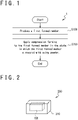
FIG. 1 is a flowchart showing a manufacturing method of oxidation resistant alloy, according to one embodiment. -
FIG. 2 is a schematic diagram of a second formed member, according to one embodiment. -
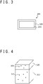
FIG. 3 is a section view of oxidation resistant alloy, according to one embodiment. -
FIG. 4 is a diagram for illustrating the structure of oxidation resistant alloy, according to one embodiment. -
FIG. 5 is a flowchart showing part of a manufacturing method of oxidation resistant alloy, according to one embodiment. -
FIG. 6 is a schematic diagram of a piece member, according to one embodiment. -
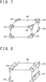
FIG. 7 is a diagram for illustrating a manufacturing process of oxidation resistant alloy, according to one embodiment. -
FIG. 8 is a diagram for illustrating a manufacturing process of oxidation resistant alloy, according to one embodiment. -
FIG. 9 is a schematic diagram of a second formed member, according to one embodiment. -
FIG. 10 is a flowchart showing part of a manufacturing method of oxidation resistant alloy, according to one embodiment. -
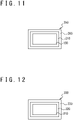
FIG. 11 is a section view of a third formed member, according to one embodiment. -
FIG. 12 is a section view of oxidation resistant alloy, according to one embodiment. -
FIG. 13 is a flowchart showing part of a manufacturing method of oxidation resistant alloy, according to one embodiment. -
FIG. 14 is a schematic diagram of a surface piece member, according to one embodiment. -
FIG. 15 is a diagram for illustrating a manufacturing process of oxidation resistant alloy, according to one embodiment. -
FIG. 16 is a perspective section view of a second formed member, according to one embodiment. - A manufacturing method 1 shown in
FIG. 1 enables manufacture of oxidation resistant alloy with a reduced cost. At step S100, a first formedmember 100 is produced by applying compression forming to metal powder. The main constitute of the metal powder includes any metal, such as molybdenum (Mo), niobium (Nb), tungsten (W), metal-silicon-based alloy, metal-boron-based alloy, and the like. The metal contained in the metal-silicon-based alloy and the metal contained in the metal-boron-based alloy may include molybdenum (Mo), niobium (Nb), tungsten (W), or the like. Both the metal-silicon-based alloy and the metal-boron-based alloy may include metal-silicon-boron-based alloy. The metal-silicon-based alloy may include, for example, Mo5Si3, Mo3Si, or the like, and the metal-boron-based alloy may include, for example, MoB, Mo2B, or the like. The metal-silicon-boron-based alloy may include Mo5SiB2 or the like. The main constitute of the powder may include material that has the highest concentration (e.g., the highest mass percentage) in the powder. - The first formed
member 100 may be produced by applying the compression forming to the metal powder without melting the metal powder. For example, the first formedmember 100 may be formed through cold isostatic pressing (CIP). Alternatively, the first formedmember 100 may be formed through molding that achieves compression forming in one direction (e.g., the vertical direction) with a metal mold. This may result in that the first formedmember 100 is formed as a non-sintered body, which is not yet sintered. - At
step 200, oxidationresistant alloy 300 is produced by applying compression forming to the first formedmember 100 in the state in which the first formedmember 100 is covered with alloy powder. The alloy powder is different from the metal powder contained in the first formedmember 100. The main constitute of the alloy powder includes oxidation resistant alloy, for example, metal-silicon-boron-based alloy. The metal contained in the metal-silicon-boron-based alloy may include molybdenum (Mo), niobium (Nb), tungsten (W), or the like, and the metal-silicon-boron-based alloy may include Mo5SiB2, Mo5Si3, Mo3Si, MoB, Mo2B, or the like. The main constitute of the alloy powder may exhibit higher oxidation resistance than the main constitute of the metal powder contained in the first formedmember 100. - The oxidation resistance may be measured as the thickness of the formed oxide from the surface or the decrease in the thickness of material (e.g., the amount of the thickness decrease of the material due to sublimation at the surface) when the material is placed in a space with a desired temperature (e.g., 1095 °C) for a desired time duration (e.g., two hours). The oxidation resistance is measured as higher as the thickness of the formed oxide is reduced or as the decrease in the thickness of the material is reduced.
- At step S200, as shown in
FIG. 2 , a second formedmember 200 may be produced by implementing the compression forming without melting the alloy powder. For example, the first formedmember 100 is covered with the alloy powder. The first formedmember 100 covered with the alloy powder is subjected to compression forming to produce the second formedmember 200. The second formedmember 200 includes anouter layer 210 that covers the first formedmember 100 and is formed of the alloy powder. For example, the first formedmember 100 may be entirely covered with the alloy powder. The second formedmember 200 may be produced through cold isostatic pressing or molding from the first formedmember 100 covered with the alloy powder. The mold used in the compression forming of step S200 may be different from the mold used in the compression forming of step S100. - Oxidation
resistant alloy 300 may be produced by sintering the second formedmember 200. The second formedmember 200 may be sintered by any methods such as spark plasma sintering (SPS) and millimeter wave sintering. For example, the second formedmember 200 may be sintered in a reducing atmosphere, for example, in hydrogen gas. - The second formed
member 200 is sintered, for example, after being detached from the mold used for the compressing forming. The second formedmember 200 is detached from the mold used for the compressing forming and placed on a floor plate jig. The floor plate jig is formed of metal suitable for the main constituent of the alloy powder. When the main constituent of the alloy powder is molybdenum compound, for example, the floor plate jig is formed of molybdenum or molybdenum compound. Further, a support jig is placed depending on the shape of the second formedmember 200. The support jig suppresses deformation of the second formedmember 200 during the sintering, for example, deformation caused by gravity. - As shown in
FIG. 3 , the oxidationresistant alloy 300 includes aninner structure 310 and anouter structure 320. Theinner structure 310 includes constituents corresponding to the constituents of the metal powder contained in the first formedmember 100. For example, the main constituent of theinner structure 310 is the same as a constituent of the first formedmember 100. Further, theouter structure 320 includes constituents corresponding to the constituents of the alloy powder that covered the first formedmember 100. For example, the main constituent of theouter structure 320 is the same as a constituent of the alloy powder that covered the first formedmember 100. - The surface of the oxidation
resistant alloy 300 exhibits high oxidation resistance. The surface of the oxidationresistant alloy 300 is formed by the outer structure. The main constituent of theouter structure 320 includes oxidation resistant alloy that is the main constituent of the alloy powder. Accordingly, the oxidationresistant alloy 300 exhibits high oxidation resistance. Further, the oxidationresistant alloy 300 may also have ductility when the main constituent of the metal powder has ductility. The main constituent of the alloy (e.g., the main constituent of the outer structure 320) may include the material with the highest concentration (e.g., the highest mass percentage) in the alloy or include five materials with the highest five concentrations. - As thus described, since the oxidation
resistant alloy 300 can be manufactured with a single sintering process, the manufacturing cost can be reduced. If oxidation resistant alloy is manufactured with coating, the surface is cleaned before the coating. The coating process and the cleaning process increase the manufacture cost compared to the manufacturing method 1. The cleaning process may involve surface processing for covering the internal structure with alloy powder, for example, removal of a surface denaturation layer. The manufacturing method 1 allows omitting this cleaning process. In addition, since the oxidationresistant alloy 300 can be manufactured to have a near net shape similar to the product shape, the manufacturing cost can be further reduced. - At step S200, the first formed
member 100 may be covered with the alloy powder such that the distribution of an element(s) contained in the main constituent of the alloy powder is even. In this case, the distribution of the element(s) contained in the main constituent of theouter structure 320 of the oxidationresistant alloy 300 manufactured by this method may be even. For example, the distribution of the element(s) contained in the main constituent of theouter structure 320 may be even in the thickness direction of theouter structure 320, not varying depending on the distance from the surface. A similar applies to theinner structure 310; the element(s) contained in the main constituent of theinner structure 310 may be evenly distributed. - Further, as shown in
FIG. 4 , since the alloy powder is subjected to compression forming and sintering, theouter structure 320 may have a plurality of substantiallyspherical voids 322 with aspect ratios of, for example, 1.3 or less. For example, 80% or more of thevoids 322 have aspect ratios of 1.3 or less. Theinner structure 310 may also have a plurality of substantiallyspherical voids 312 with aspect ratios of, for example, 1.3 or less. For example, 80% or more of thevoids 312 have aspect ratios of 1.3 or less. The density of theouter structure 320 may be 90% or more. The density of theinner structure 310 may also be 90% or more. - The above-described structure may distinguish the oxidation
resistant alloy 300 manufactured by the present method from alloy manufactured using a coating process. The even distribution may mean that the concentration of an element does not vary 10% or more. - The concentration of an element may be measured by an electron probe micro analyzer (EPMA). For example, element constituents are measured on a plurality of section surfaces of the
inner structure 310 or theouter structure 320 with an electron probe micro analyzer. The element distributions may be measured in this way. The shapes of thevoids inner structure 310 and theouter structure 320. - The main constituent of the alloy powder may include compound of the main constituent of the metal powder. In this case, the metal that forms the main constituent of the
outer structure 320 may be the same as the metal that forms the main constituent of theinner structure 310. This enhances the coupling strength between theouter structure 320 and theinner structure 310. - At step S200, the compression forming and sintering may be simultaneously implemented. For example, the oxidation
resistant alloy 300 may be produced by applying compression forming to the first formedmember 100 through hot isostatic pressing (HIP) in the state in which the first formedmember 100 is covered with the alloy powder. - A method shown in
FIG. 5 may be implemented at step S200. At step S210,piece members 220 are produced by applying compression forming to alloy powder. As shown inFIG. 6 , apiece member 220 has a plurality of contact surfaces 225 which may be placed in contact with the first formedmember 100 and is configured such that thepiece member 220 can be placed at a corner of the first formedmember 100, in embodiments where the first formedmember 100 is shaped as a cuboid, for example, at a vertex of the cuboid. The thickness L1 of thepiece member 220 may be thinner than the thickness of theouter layer 210. For example, the thickness L1 of thepiece members 220 may be 90% or less of the thickness of theouter layer 210. The thickness L1 may be 80% or less of the thickness of theouter layer 210. - The
piece members 220 may be produced by implementing the compression forming without melting the alloy powder. For example, thepiece members 220 may be formed through cold isostatic pressing (CIP) or molding. - At step S220, as shown in
FIG. 7 , thepiece members 220 are placed to support the first formedmember 100. For example, thepiece members 220 are placed at at least some of the corners of the first formedmember 100. Thepiece members 220 may be placed at the vertices of the first formedmember 100. As shown inFIG. 8 , thepiece members 220 may be each placed at a boundary between two flat or curved surfaces, for example, along an edge of the cuboid. - At step S230, the oxidation
resistant alloy 300 is produced by covering the first formedmember 100 with alloy powder and applying compression forming to the first formedmember 100 in the state in which the first formedmember 100 is covered with the alloy powder. The first formedmember 100 is covered with the alloy powder in the state in which the first formedmember 100 is supported by thepiece members 220. The first formedmember 100 covered with the alloy powder is subjected to compression forming. - At step S230, as shown in
FIG. 9 , a second formedmember 200 may be produced by implementing the compression forming without melting the alloy powder. The first formedmember 100 is covered with thepiece members 220, which are formed of the alloy powder, and theouter layer 210. The second formedmember 200 may be produced through cold isostatic pressing or molding. The oxidationresistant alloy 300 is then produced by sintering the second formedmember 200 with a desired method. - As thus described, the
piece members 220 may be used to manufacture the oxidationresistant alloy 300. By supporting the first formedmember 100 with thepiece members 220, theouter structure 320 of the oxidizationresistant alloy 300 may have an even thickness. This manufacturing method can reduce exposure of theinner structure 310 of the oxidationresistant alloy 300 onto the surface of the oxidationresistant alloy 300. - At step S230, the compression forming and the sintering may be simultaneously implemented. For example, compression forming of the first formed
member 100 covered with the alloy powder may be achieved through hot isostatic pressing. - A method shown in
FIG. 10 may be implemented at step S200. At step S250, a second formedmember 200 is produced by applying compression forming to the first formedmember 100 in the state in which the first formedmember 100 is covered with the alloy powder. For example, the first formedmember 100 is covered with the alloy powder. The second formedmember 200 is produced by applying compression forming to the first formedmember 100 covered with the alloy powder. - The second formed
member 200 may be produced by implementing the compression forming without melting the alloy powder. For example, the second formedmember 200 may be produced from the first formedmember 100 covered with the alloy powder through cold isostatic pressing or molding. - At step S260, oxidation
resistant alloy 300 is produced by applying compression forming to the second formedmember 200 in the state in which the second formedmember 200 is covered with oxide powder. For example, the second formedmember 200 is covered with the oxide powder. The oxide powder may include, for example, part of aluminum oxide (Al2O3), yttrium oxide (Y2O3), chromium oxide (Cr2O3), zirconia (ZrO2), yttrium-stabilized zirconia (YSZ), magnesium oxide (MgO), and hafnium oxide (HfO2). - At step S260, as shown in
FIG. 11 , a third formedmember 250 may be produced by implementing the compression forming without melting the oxide powder. The first formedmember 100 is covered with anouter layer 210 formed of alloy powder. The second formedmember 200, for example, theouter layer 210 is covered with anoxide layer 260 formed of the oxide powder. The second formedmember 200 may be entirely covered with the oxide powder. The third formedmember 250 may be produced through cold isostatic pressing or molding. Oxidationresistant alloy 300 is then produced by sintering the third formedmember 250 with a desired method. - As shown in
FIG. 12 , the oxidationresistant alloy 300 thus manufactured includes aninner structure 310, anouter structure 320, and asurface layer 330. Since thesurface layer 330 is formed of oxide, the oxidationresistant alloy 300 exhibits high oxidation resistance. Theinner structure 310 and theouter structure 320 are formed in the same way as those of the oxidationresistant alloy 300 shown inFIG. 3 , and therefore no description is given here of theinner structure 310 and theouter structure 320. Further, since the oxidationresistant alloy 300 can be manufactured with a single sintering process, the manufacturing cost is reduced. - At step S260, the compression forming and the sintering may be simultaneously implemented. For example, compression forming of the second formed
member 200 covered with the oxide powder may be achieved through hot isostatic pressing. - A process shown in
FIG. 10 may be performed in step S230 shown inFIG. 5 . In this case, atstep 250, the first formedmember 100 is covered with alloy powder in the state in which the first formedmember 100 is supported by thepiece members 220, and the first formedmember 100 covered with the alloy powder is subjected to compression forming to produce the second formedmember 200. The subsequent process is the same as that of embodiment 3, and therefore no description of the subsequent process is given here. - A process shown in
FIG. 13 may be implemented at step S260 shown inFIG. 10 . At step 261, as shown inFIG. 14 ,surface piece members 420 are formed by applying compression forming to oxide powder. Asurface pixel member 420 has a plurality of contact surfaces 425 that may be placed in contact with the second formedmember 200 and is configured such that thesurface piece member 420 can be placed at a corner of the second formedmember 200. The thickness L2 of thesurface piece member 420 may be thinner than the thickness of theoxidation layer 260. For example, the thickness L2 of thesurface piece member 420 may be 90% or less of the thickness of theoxide layer 260. The thickness L2 may be 80% or less of the thickness of theoxide layer 260. - The
surface piece members 420 may be produced by implementing the compression forming without melting the oxide powder. For example, thesurface piece members 420 may be formed through cold isostatic pressing (CIP) or molding. - At step S262, as shown in
FIG. 15 , thesurface piece members 420 are placed to support the second formedmember 200. For example, thesurface piece members 420 are placed at at least some of the corners of the second formedmember 200. Thesurface piece members 420 may be placed at the vertices of the second formedmember 200. - At step S263, oxidation
resistant alloy 300 is produced by covering the second formedmember 200 with oxide powder and applying compression forming to the second formedmember 200 covered with the oxide powder. The second formedmember 200 is covered with the oxide powder in the state in which the second formedmember 200 is supported by thesurface piece members 420. The second formedmember 200 covered with the oxide powder is subjected to compression forming. - At step S263, a third formed
member 250 may be produced by implementing compression forming without melting the oxide powder. The second formedmember 200 is covered withsurface piece members 420 and oxide powder, where thesurface piece members 420 are formed of oxide powder. The third formedmember 250 may be produced through cold isostatic pressing or molding. Oxidationresistant alloy 300 may be then produced by sintering the third formedmember 250 with a desired method. - As thus described, the oxidation
resistant alloy 300 may be manufactured using thesurface piece members 420. By supporting the second formedmember 200 with thesurface piece members 420, thesurface layer 330 of the oxidationresistant alloy 300 may have an even thickness. This manufacturing method can reduce exposure of theouter structure 320 and theinner structure 310 of the oxidationresistant alloy 300 onto the surface of the oxidationresistant alloy 300. - At step 263, the compression forming and the sintering may be simultaneously implemented. For example, compression forming of the second formed
member 200 covered with the oxide powder may be achieved by hot isostatic pressing. - The oxidization
resistant alloy 300 may be manufactured in any shapes achievable with compression forming. For example, the oxidationresistant alloy 300 may be manufactured in a conical shape. In this case, as shown inFIG. 16 ,piece members 220 may be disposed at the vertex of the cone and along the edge between the base and the side surface. - The oxidation
resistant alloy 300 may include a multi-layeredouter structure 320. For example, theouter structure 320 may be configured such that the closer the layers are to the surface of the oxidationresistant alloy 300, the higher oxidation resistances the layers exhibit. Such oxidationresistant alloy 300 may be manufactured by repeating step S200 ofFIG. 1 . In this case, the sintering process may be performed after all the layers are formed through compression forming. For example, the respective layers are subjected to compression forming without melting the alloy powder. The sintering process is implemented after all the layers are formed through compression forming without melting the alloy powder. If sintering and compression forming are repeated, this may make the layeredouter structure 320 brittle and fragile compared to theinner structure 310. By implementing the sintering process after forming the layeredouter structure 320 through compression forming, it is possible to manufacture the oxidationresistant alloy 300 without destroying the layered structure. - The metal powder may include an element that can reinforce the first metal by doping, for example, titanium (Ti), zirconium (Zr), hafnium (Hf), tungsten (W), tantalum (Ta), carbon (C), or the like. This provides higher strength for the oxidation
resistant alloy 300. - The metal powder may include the main constituent of the alloy powder that covers the first formed
member 100. This makes it easy to bond theinner structure 310 to theouter structure 320. - The alloy powder or the oxidation powder may include an element that reacts to oxygen more easily than the main constituent of the first formed member 100 (e.g., the element with the highest mass percentage concentration in the first formed member 100), such as, aluminum (Al), magnesium (Mg), calcium (Ca), niobium (Nb), chromium (Cr), titanium (Ti), rare-earth elements, or the like. This provides higher oxidation resistance to the oxidation
resistant alloy 300. - The
surface layer 330 may be formed of ceramics. In this case, the oxidationresistant alloy 300 is produced by applying compression forming to the second formedmember 200 at step S260 shown inFIG. 10 in the state in which the second formedmember 200 is covered with ceramic precursor powder. The process is similar to those in Embodiments 3-4 except for that the ceramic precursor powder is used in place of the oxide powder, and therefore no description of the process is given here. Also, thesurface piece members 420 may be formed through compression forming of ceramic precursor powder at step S261 ofFIG. 13 . The process is similar to that of Embodiment 5 except for that the ceramic precursor powder is used in place of the oxide powder, and therefore no description of the process is given here. - The above-described embodiments and modification examples are construed as mere examples and may be modified as long as the function is not disturbed. Further, the configurations described in the respective embodiments and modification examples may be arbitrarily modified and/or combined as long as the function is not disturbed.
- Manufacturing methods of oxidation resistant alloy described in the respective embodiments can be represented, for example, as follows.
- A manufacturing method of oxidation resistant alloy according to a first aspect includes: producing (S100) a first formed member (100) by applying compression forming to metal powder; and applying compression forming (S200) to the first formed member (100) in a state in which the first formed member is covered with alloy powder different from the metal powder. The oxidation resistance of a major constituent of the alloy powder is higher than oxidation resistance of a major constituent of the metal powder.
- The oxidation resistant alloy (300) thus manufactured includes an inner structure (310) and an outer structure (320) that covers the inner structure (310) while the oxidation resistance of the outer structure (320) is higher than the oxidation resistance of the inner structure (310). Accordingly, the oxidation resistant alloy (300) thus manufactured exhibits high oxidation resistance.
- The manufacturing method according to a second aspect is a variation of the manufacturing method according to the first aspect. In the manufacturing method according to the second aspect, producing the first formed member (100) includes applying the compression forming to the metal powder without melting the metal powder.
- Since the first formed member (100) is a non-sintered body formed without being sintered, the manufacturing cost can be reduced.
- The manufacturing method according to a third aspect is a variation of the manufacturing method according to the first aspect. In the manufacturing method according to the third aspect, applying the compression forming (S200) to the first formed member (100) includes: producing a second formed member (200) by applying compression forming to the alloy powder without melting the alloy powder; and sintering the second formed member.
- The manufacturing method of oxidation resistant alloy according to a fourth aspect is a variation of the manufacturing method according to the first aspect. In the manufacturing method according to the fourth aspect, applying the compression forming (S200) to the first formed member (100) includes: producing (S210) a piece member (220) through compression forming of the alloy powder; and supporting (S220) the first formed member (100) with the piece member (220). Applying the compression forming (S200) to the first formed member (100) further includes covering (S230) the first formed member (100) with the alloy powder.
- The manufacturing method of oxidation resistant alloy according to a fifth aspect is a variation of the manufacturing method according to the fourth aspect. In the manufacturing method according to the fifth aspect, supporting (S220) the first formed member (100) includes placing the piece member (220) at a corner of the first formed member (100).
- This may allow the outer structure (320) to have an even thickness. Accordingly, it is possible to reduce exposure of the inner structure (310) onto the surface of the oxidation resistant alloy (300).
- The manufacturing method according to a sixth aspect is a variation of the manufacturing method according to the fourth aspect. In the manufacturing method according to the sixth aspect, producing the piece member (220) includes implementing the compression forming to the alloy powder without melting the alloy powder.
- Since the piece member (220) is formed without being sintered, the manufacture cost can be reduced.
- The manufacturing method of oxidation resistant alloy according to a seventh aspect is a variation of the manufacturing method according to the first aspect. In the manufacturing method according to the seventh aspect, the main constituent of the metal powder includes first metal, and the main constituent of the alloy powder includes compound of the first metal.
- The manufacturing method of oxidation resistant alloy according to an eighth aspect is a variation of the manufacturing method according to the first aspect. In the manufacturing method according to the eighth aspect, the metal powder includes the main constituent of the alloy powder.
- This enhances the coupling strength between the first structure (310) and the second structure (320).
- The manufacturing method of oxidation resistant metal according to a ninth aspect is a variation of the manufacturing method according to the first aspect. In the manufacturing method according to the ninth aspect, applying compression forming (S200) to the first formed member (100) includes entirely covering the first formed member (100) with the alloy powder.
- The manufacturing method of oxidation resistant alloy according to a tenth aspect is a variation of the manufacturing method according to the first aspect. In the manufacturing method according to the tenth aspect, applying compression forming (S200) to the first formed member (100) includes: producing a second formed member (200) by applying compression forming to the first formed member (100) in the state in which the first formed member is covered with the alloy powder; and applying compression forming (S260) to the second formed member (200) in a state in which the second formed member is covered with oxide powder or ceramic precursor powder.
- The oxidation resistant alloy (300) thus manufactured includes a surface layer (330). Since the surface layer (330), which exhibits high oxidation resistance, covers the outer structure (320), the oxidation resistant alloy (300) can have high oxidation resistance.
- Oxidation resistant alloys described in the respective embodiments can be represented, for example, as follows.
- Oxidation resistant alloy according to an eleventh aspect includes: an inner structure (310) that includes first metal as a main constituent; and an outer structure (320) containing an element that forms compound with the first metal, the outer structure covering the inner structure. In the outer structure (320), a distribution of the element that forms the compound with the first metal is even in a thickness direction of the outer structure (320). The concentration of the compound of the first metal in the outer structure (320) is different from the concentration of the compound of the first metal in the inner structure (310). The outer structure (320) has a plurality of voids (322) with aspect ratios of 1.3 or less.
- With the above-described manufacturing methods, oxidation resistant alloy (300) thus configured is manufactured. The manufactured oxidation resistant alloy (300) exhibits high oxidation resistance.
- The present application claims priority to
Japanese patent application No. 2020-057413, filed on March 27, 2020
Claims (11)
- A manufacturing method of oxidation resistant alloy, the method comprising:producing a first formed member by applying compression forming to metal powder; andapplying compression forming to the first formed member in a state in which the first formed member is covered with alloy powder different from the metal powder,wherein oxidation resistance of a maj or constituent of the alloy powder is higher than oxidation resistance of a major constituent of the metal powder.
- The manufacturing method according to claim 1, wherein producing the first formed member comprises applying the compression forming to the metal powder without melting the metal powder.
- The manufacturing method according to claim 1 or 2, wherein applying the compression forming to the first formed member comprises:producing a second formed member by applying compression forming to the alloy powder without melting the alloy powder; andsintering the second formed member.
- The manufacturing method according to any one of claims 1 to 3, wherein applying the compression forming to the first formed member comprises:producing a piece member through compression forming to the alloy powder;supporting the first formed member with the piece member; andcovering the first formed member with the alloy powder.
- The manufacturing method according to claim 4, wherein supporting the first formed member comprises placing the piece member at a corner of the first formed member.
- The manufacturing method according to claim 4 or 5, wherein producing the piece member comprises implementing the compression forming to the alloy powder without melting the alloy powder.
- The manufacturing method according to any one of claims 1 to 6, wherein the main constituent of the metal powder comprises first metal, and wherein the main constituent of the alloy powder comprises compound of the first metal.
- The manufacturing method according to any one of claims 1 to 7, wherein the metal powder comprises the main constituent of the alloy powder.
- The manufacturing method according to any one of claims 1 to 8, wherein applying the compression forming to the first formed member comprises entirely covering the first formed member with the alloy powder.
- The manufacturing method according to any one of claims 1 to 9, wherein applying the compression forming to the first formed member comprises:producing a second formed member by applying compression forming to the first formed member in the state in which the first formed member is covered with the alloy powder; andapplying compression forming to the second formed member in a state in which the second formed member is covered with oxide powder or ceramic precursor powder.
- Oxidization resistant alloy, comprising:an inner structure comprising first metal as a main constituent; andan outer structure comprising an element that forms compound with the first metal, the outer structure covering the inner structure,wherein, in the outer structure, a distribution of the element is even in a thickness direction of the outer structure,wherein a concentration of the element in the outer structure is different from a concentration of the element in the inner structure, andwherein the outer structure has a plurality of voids with aspect ratios of 1.3 or less.
Applications Claiming Priority (2)
| Application Number | Priority Date | Filing Date | Title |
|---|---|---|---|
| JP2020057413A JP7438812B2 (en) | 2020-03-27 | 2020-03-27 | Oxidation-resistant alloy and method for producing oxidation-resistant alloy |
| PCT/JP2021/001863 WO2021192554A1 (en) | 2020-03-27 | 2021-01-20 | Oxidation-resistant alloy, and method for producing oxidation-resistant alloy |
Publications (3)
| Publication Number | Publication Date |
|---|---|
| EP3995234A1 true EP3995234A1 (en) | 2022-05-11 |
| EP3995234A4 EP3995234A4 (en) | 2022-09-07 |
| EP3995234B1 EP3995234B1 (en) | 2024-07-17 |
Family
ID=77890097
Family Applications (1)
| Application Number | Title | Priority Date | Filing Date |
|---|---|---|---|
| EP21775074.4A Active EP3995234B1 (en) | 2020-03-27 | 2021-01-20 | Method for producing oxidation-resistant alloy |
Country Status (5)
| Country | Link |
|---|---|
| US (1) | US11951546B2 (en) |
| EP (1) | EP3995234B1 (en) |
| JP (1) | JP7438812B2 (en) |
| AU (1) | AU2021243424B2 (en) |
| WO (1) | WO2021192554A1 (en) |
Cited By (1)
| Publication number | Priority date | Publication date | Assignee | Title |
|---|---|---|---|---|
| US12569942B2 (en) | 2019-07-09 | 2026-03-10 | Oerlikon Metco (Us) Inc. | Iron-based alloys designed for wear and corrosion resistance |
Families Citing this family (1)
| Publication number | Priority date | Publication date | Assignee | Title |
|---|---|---|---|---|
| CA3095046A1 (en) | 2018-03-29 | 2019-10-03 | Oerlikon Metco (Us) Inc. | Reduced carbides ferrous alloys |
Family Cites Families (20)
| Publication number | Priority date | Publication date | Assignee | Title |
|---|---|---|---|---|
| JPS4322484B1 (en) * | 1966-01-11 | 1968-09-27 | ||
| JPH0647701B2 (en) * | 1984-12-14 | 1994-06-22 | 株式会社東芝 | Electrical connection terminal clip for magnetron filament repairing |
| JPH0689379B2 (en) * | 1985-10-18 | 1994-11-09 | 住友電気工業株式会社 | Structural component having porous layer on surface and method of manufacturing the same |
| JPH03232906A (en) | 1990-02-06 | 1991-10-16 | Daido Steel Co Ltd | Composite sintered product |
| US5393484A (en) * | 1991-10-18 | 1995-02-28 | Fujitsu Limited | Process for producing sintered body and magnet base |
| JPH05320717A (en) * | 1992-05-18 | 1993-12-03 | Tokyo Seiko Co Ltd | Manufacturing method of composite sintered compacts by powder metallurgy |
| JPH073306A (en) * | 1992-09-17 | 1995-01-06 | Shuichi Kamoda | High strength cemented carbide composite material and method for producing the same |
| US5693156A (en) | 1993-12-21 | 1997-12-02 | United Technologies Corporation | Oxidation resistant molybdenum alloy |
| US6524405B1 (en) | 2000-02-11 | 2003-02-25 | Hui Lin | Iron base high temperature alloy |
| US6660225B2 (en) | 2000-12-11 | 2003-12-09 | Advanced Materials Technologies Pte, Ltd. | Method to form multi-material components |
| JP5079940B2 (en) | 2000-12-22 | 2012-11-21 | 日本特殊陶業株式会社 | Tungsten carbide cemented carbide composite material sintered body |
| JP3735717B2 (en) | 2002-09-24 | 2006-01-18 | 国立大学法人東北大学 | Mo-Si-B alloy |
| WO2010050542A1 (en) | 2008-10-29 | 2010-05-06 | Ntn株式会社 | Hard multilayer film formed body and method for manufacturing same |
| JP5393108B2 (en) | 2008-10-29 | 2014-01-22 | Ntn株式会社 | Manufacturing method of hard multilayer film molded body |
| GB0922488D0 (en) | 2009-12-23 | 2010-02-03 | Advanced Interactive Materials | Improvements in or relating to hot isostatic pressing |
| DE102011111300A1 (en) * | 2011-08-26 | 2013-02-28 | Umicore Ag & Co. Kg | Process for producing a semifinished product for electrical contacts and contact piece |
| JP6157937B2 (en) | 2013-06-07 | 2017-07-05 | 株式会社東芝 | Valve device and manufacturing method thereof |
| US10240229B2 (en) | 2014-05-26 | 2019-03-26 | Oerlikon Surface Solutions Ag, Pfäffikon | Mo—Si—B layers and method for the production thereof |
| CN106663075B (en) | 2014-09-02 | 2020-12-11 | 起元科技有限公司 | Execute graph-based program specification |
| JP7035820B2 (en) | 2018-06-05 | 2022-03-15 | 住友電気工業株式会社 | Base material and cutting tools |
-
2020
- 2020-03-27 JP JP2020057413A patent/JP7438812B2/en active Active
-
2021
- 2021-01-20 EP EP21775074.4A patent/EP3995234B1/en active Active
- 2021-01-20 US US17/632,650 patent/US11951546B2/en active Active
- 2021-01-20 WO PCT/JP2021/001863 patent/WO2021192554A1/en not_active Ceased
- 2021-01-20 AU AU2021243424A patent/AU2021243424B2/en active Active
Cited By (1)
| Publication number | Priority date | Publication date | Assignee | Title |
|---|---|---|---|---|
| US12569942B2 (en) | 2019-07-09 | 2026-03-10 | Oerlikon Metco (Us) Inc. | Iron-based alloys designed for wear and corrosion resistance |
Also Published As
| Publication number | Publication date |
|---|---|
| US11951546B2 (en) | 2024-04-09 |
| US20220274168A1 (en) | 2022-09-01 |
| JP7438812B2 (en) | 2024-02-27 |
| WO2021192554A1 (en) | 2021-09-30 |
| JP2021155807A (en) | 2021-10-07 |
| AU2021243424B2 (en) | 2023-10-19 |
| EP3995234B1 (en) | 2024-07-17 |
| AU2021243424A1 (en) | 2022-02-24 |
| EP3995234A4 (en) | 2022-09-07 |
Similar Documents
| Publication | Publication Date | Title |
|---|---|---|
| US7582367B2 (en) | Ceramic member and manufacturing method for the same | |
| KR101963521B1 (en) | Ceramic structure, member for substrate holding device, and method for manufacturing ceramic structure | |
| US9457405B2 (en) | Metallic crucibles and methods of forming the same | |
| US11951546B2 (en) | Oxidation resistant alloy and manufacturing method of oxidation resistant alloy | |
| US20120318669A1 (en) | Sputtering target-backing plate assembly | |
| US12522913B2 (en) | Sputtering target | |
| JP2010219045A6 (en) | Interconnector for high-temperature solid electrolyte fuel cells | |
| KR20130046411A (en) | Heat resistant coated member, making method, and treatment using the same | |
| US20090233087A1 (en) | Yttrium oxide material, member for semiconductor-manufacturing apparatus, and method for producing yttrium oxide material | |
| JP2023041692A (en) | Ceramic member and cutting tool | |
| KR101189184B1 (en) | Sintered body for thermal barrier coating, method for manufacturing the same and method for manufacturing double-layered thermal barrier using the same | |
| JP2004281392A (en) | High melting point metal material provided with oxide film layer, method for producing the same, and sintering plate using the same | |
| JPH0499146A (en) | Powder sintered material and its manufacture | |
| JP7498015B2 (en) | Holding device and method for manufacturing the same | |
| JP4771513B2 (en) | Heat-resistant covering material | |
| JP4693399B2 (en) | Method for producing ceramic-metal composite | |
| JP2003129149A (en) | Manufacturing method of linear expansion control composite material | |
| JPH0560242A (en) | Vacuum container made of ceramics and manufacturing method thereof | |
| JPH0892606A (en) | Production of sintered compact of metal powder | |
| KR100885698B1 (en) | Manufacturing Method of Ru-based Intermetallic Compounds for High Temperature Materials with Single Phase Structure | |
| JP2023088495A (en) | YAG-based sintered body and members for semiconductor manufacturing equipment | |
| JPH11228236A (en) | Adhesion-preventing material for sintering ceramic and production of ceramic sintered product | |
| JPH03115506A (en) | Manufacture of combined sintered material | |
| JP2002020170A (en) | TiN-Al2O3 SINTERED COMPACT | |
| JP2006199515A (en) | Heat-resistant coating member |
Legal Events
| Date | Code | Title | Description |
|---|---|---|---|
| STAA | Information on the status of an ep patent application or granted ep patent |
Free format text: STATUS: THE INTERNATIONAL PUBLICATION HAS BEEN MADE |
|
| PUAI | Public reference made under article 153(3) epc to a published international application that has entered the european phase |
Free format text: ORIGINAL CODE: 0009012 |
|
| STAA | Information on the status of an ep patent application or granted ep patent |
Free format text: STATUS: REQUEST FOR EXAMINATION WAS MADE |
|
| 17P | Request for examination filed |
Effective date: 20220201 |
|
| AK | Designated contracting states |
Kind code of ref document: A1 Designated state(s): AL AT BE BG CH CY CZ DE DK EE ES FI FR GB GR HR HU IE IS IT LI LT LU LV MC MK MT NL NO PL PT RO RS SE SI SK SM TR |
|
| REG | Reference to a national code |
Ref country code: DE Ref legal event code: R079 Free format text: PREVIOUS MAIN CLASS: B22F0007060000 Ipc: B22F0003030000 Ref country code: DE Ref legal event code: R079 Ref document number: 602021015916 Country of ref document: DE Free format text: PREVIOUS MAIN CLASS: B22F0007060000 Ipc: B22F0003030000 |
|
| A4 | Supplementary search report drawn up and despatched |
Effective date: 20220805 |
|
| RIC1 | Information provided on ipc code assigned before grant |
Ipc: B22F 3/105 20060101ALN20220801BHEP Ipc: C22C 1/04 20060101ALI20220801BHEP Ipc: B22F 7/06 20060101ALI20220801BHEP Ipc: B22F 3/04 20060101ALI20220801BHEP Ipc: B22F 3/03 20060101AFI20220801BHEP |
|
| DAV | Request for validation of the european patent (deleted) | ||
| DAX | Request for extension of the european patent (deleted) | ||
| STAA | Information on the status of an ep patent application or granted ep patent |
Free format text: STATUS: EXAMINATION IS IN PROGRESS |
|
| 17Q | First examination report despatched |
Effective date: 20230929 |
|
| GRAP | Despatch of communication of intention to grant a patent |
Free format text: ORIGINAL CODE: EPIDOSNIGR1 |
|
| RIC1 | Information provided on ipc code assigned before grant |
Ipc: B22F 3/105 20060101ALN20240109BHEP Ipc: C22C 1/04 20060101ALI20240109BHEP Ipc: B22F 7/06 20060101ALI20240109BHEP Ipc: B22F 3/04 20060101ALI20240109BHEP Ipc: B22F 3/03 20060101AFI20240109BHEP |
|
| STAA | Information on the status of an ep patent application or granted ep patent |
Free format text: STATUS: GRANT OF PATENT IS INTENDED |
|
| INTG | Intention to grant announced |
Effective date: 20240215 |
|
| GRAS | Grant fee paid |
Free format text: ORIGINAL CODE: EPIDOSNIGR3 |
|
| GRAA | (expected) grant |
Free format text: ORIGINAL CODE: 0009210 |
|
| STAA | Information on the status of an ep patent application or granted ep patent |
Free format text: STATUS: THE PATENT HAS BEEN GRANTED |
|
| AK | Designated contracting states |
Kind code of ref document: B1 Designated state(s): AL AT BE BG CH CY CZ DE DK EE ES FI FR GB GR HR HU IE IS IT LI LT LU LV MC MK MT NL NO PL PT RO RS SE SI SK SM TR |
|
| REG | Reference to a national code |
Ref country code: CH Ref legal event code: EP |
|
| REG | Reference to a national code |
Ref country code: DE Ref legal event code: R096 Ref document number: 602021015916 Country of ref document: DE |
|
| REG | Reference to a national code |
Ref country code: IE Ref legal event code: FG4D |
|
| REG | Reference to a national code |
Ref country code: LT Ref legal event code: MG9D |
|
| REG | Reference to a national code |
Ref country code: NL Ref legal event code: MP Effective date: 20240717 |
|
| PG25 | Lapsed in a contracting state [announced via postgrant information from national office to epo] |
Ref country code: PT Free format text: LAPSE BECAUSE OF FAILURE TO SUBMIT A TRANSLATION OF THE DESCRIPTION OR TO PAY THE FEE WITHIN THE PRESCRIBED TIME-LIMIT Effective date: 20241118 |
|
| PG25 | Lapsed in a contracting state [announced via postgrant information from national office to epo] |
Ref country code: NL Free format text: LAPSE BECAUSE OF FAILURE TO SUBMIT A TRANSLATION OF THE DESCRIPTION OR TO PAY THE FEE WITHIN THE PRESCRIBED TIME-LIMIT Effective date: 20240717 |
|
| PG25 | Lapsed in a contracting state [announced via postgrant information from national office to epo] |
Ref country code: PT Free format text: LAPSE BECAUSE OF FAILURE TO SUBMIT A TRANSLATION OF THE DESCRIPTION OR TO PAY THE FEE WITHIN THE PRESCRIBED TIME-LIMIT Effective date: 20241118 Ref country code: NL Free format text: LAPSE BECAUSE OF FAILURE TO SUBMIT A TRANSLATION OF THE DESCRIPTION OR TO PAY THE FEE WITHIN THE PRESCRIBED TIME-LIMIT Effective date: 20240717 |
|
| PG25 | Lapsed in a contracting state [announced via postgrant information from national office to epo] |
Ref country code: NO Free format text: LAPSE BECAUSE OF FAILURE TO SUBMIT A TRANSLATION OF THE DESCRIPTION OR TO PAY THE FEE WITHIN THE PRESCRIBED TIME-LIMIT Effective date: 20241017 |
|
| PG25 | Lapsed in a contracting state [announced via postgrant information from national office to epo] |
Ref country code: FI Free format text: LAPSE BECAUSE OF FAILURE TO SUBMIT A TRANSLATION OF THE DESCRIPTION OR TO PAY THE FEE WITHIN THE PRESCRIBED TIME-LIMIT Effective date: 20240717 Ref country code: PL Free format text: LAPSE BECAUSE OF FAILURE TO SUBMIT A TRANSLATION OF THE DESCRIPTION OR TO PAY THE FEE WITHIN THE PRESCRIBED TIME-LIMIT Effective date: 20240717 Ref country code: GR Free format text: LAPSE BECAUSE OF FAILURE TO SUBMIT A TRANSLATION OF THE DESCRIPTION OR TO PAY THE FEE WITHIN THE PRESCRIBED TIME-LIMIT Effective date: 20241018 |
|
| PG25 | Lapsed in a contracting state [announced via postgrant information from national office to epo] |
Ref country code: BG Free format text: LAPSE BECAUSE OF FAILURE TO SUBMIT A TRANSLATION OF THE DESCRIPTION OR TO PAY THE FEE WITHIN THE PRESCRIBED TIME-LIMIT Effective date: 20240717 |
|
| PG25 | Lapsed in a contracting state [announced via postgrant information from national office to epo] |
Ref country code: LV Free format text: LAPSE BECAUSE OF FAILURE TO SUBMIT A TRANSLATION OF THE DESCRIPTION OR TO PAY THE FEE WITHIN THE PRESCRIBED TIME-LIMIT Effective date: 20240717 |
|
| PG25 | Lapsed in a contracting state [announced via postgrant information from national office to epo] |
Ref country code: IS Free format text: LAPSE BECAUSE OF FAILURE TO SUBMIT A TRANSLATION OF THE DESCRIPTION OR TO PAY THE FEE WITHIN THE PRESCRIBED TIME-LIMIT Effective date: 20241117 |
|
| PG25 | Lapsed in a contracting state [announced via postgrant information from national office to epo] |
Ref country code: HR Free format text: LAPSE BECAUSE OF FAILURE TO SUBMIT A TRANSLATION OF THE DESCRIPTION OR TO PAY THE FEE WITHIN THE PRESCRIBED TIME-LIMIT Effective date: 20240717 |
|
| PG25 | Lapsed in a contracting state [announced via postgrant information from national office to epo] |
Ref country code: ES Free format text: LAPSE BECAUSE OF FAILURE TO SUBMIT A TRANSLATION OF THE DESCRIPTION OR TO PAY THE FEE WITHIN THE PRESCRIBED TIME-LIMIT Effective date: 20240717 Ref country code: RS Free format text: LAPSE BECAUSE OF FAILURE TO SUBMIT A TRANSLATION OF THE DESCRIPTION OR TO PAY THE FEE WITHIN THE PRESCRIBED TIME-LIMIT Effective date: 20241017 |
|
| PG25 | Lapsed in a contracting state [announced via postgrant information from national office to epo] |
Ref country code: RS Free format text: LAPSE BECAUSE OF FAILURE TO SUBMIT A TRANSLATION OF THE DESCRIPTION OR TO PAY THE FEE WITHIN THE PRESCRIBED TIME-LIMIT Effective date: 20241017 Ref country code: PL Free format text: LAPSE BECAUSE OF FAILURE TO SUBMIT A TRANSLATION OF THE DESCRIPTION OR TO PAY THE FEE WITHIN THE PRESCRIBED TIME-LIMIT Effective date: 20240717 Ref country code: NO Free format text: LAPSE BECAUSE OF FAILURE TO SUBMIT A TRANSLATION OF THE DESCRIPTION OR TO PAY THE FEE WITHIN THE PRESCRIBED TIME-LIMIT Effective date: 20241017 Ref country code: LV Free format text: LAPSE BECAUSE OF FAILURE TO SUBMIT A TRANSLATION OF THE DESCRIPTION OR TO PAY THE FEE WITHIN THE PRESCRIBED TIME-LIMIT Effective date: 20240717 Ref country code: IS Free format text: LAPSE BECAUSE OF FAILURE TO SUBMIT A TRANSLATION OF THE DESCRIPTION OR TO PAY THE FEE WITHIN THE PRESCRIBED TIME-LIMIT Effective date: 20241117 Ref country code: HR Free format text: LAPSE BECAUSE OF FAILURE TO SUBMIT A TRANSLATION OF THE DESCRIPTION OR TO PAY THE FEE WITHIN THE PRESCRIBED TIME-LIMIT Effective date: 20240717 Ref country code: GR Free format text: LAPSE BECAUSE OF FAILURE TO SUBMIT A TRANSLATION OF THE DESCRIPTION OR TO PAY THE FEE WITHIN THE PRESCRIBED TIME-LIMIT Effective date: 20241018 Ref country code: FI Free format text: LAPSE BECAUSE OF FAILURE TO SUBMIT A TRANSLATION OF THE DESCRIPTION OR TO PAY THE FEE WITHIN THE PRESCRIBED TIME-LIMIT Effective date: 20240717 Ref country code: ES Free format text: LAPSE BECAUSE OF FAILURE TO SUBMIT A TRANSLATION OF THE DESCRIPTION OR TO PAY THE FEE WITHIN THE PRESCRIBED TIME-LIMIT Effective date: 20240717 Ref country code: BG Free format text: LAPSE BECAUSE OF FAILURE TO SUBMIT A TRANSLATION OF THE DESCRIPTION OR TO PAY THE FEE WITHIN THE PRESCRIBED TIME-LIMIT Effective date: 20240717 |
|
| PG25 | Lapsed in a contracting state [announced via postgrant information from national office to epo] |
Ref country code: RO Free format text: LAPSE BECAUSE OF FAILURE TO SUBMIT A TRANSLATION OF THE DESCRIPTION OR TO PAY THE FEE WITHIN THE PRESCRIBED TIME-LIMIT Effective date: 20240717 Ref country code: SM Free format text: LAPSE BECAUSE OF FAILURE TO SUBMIT A TRANSLATION OF THE DESCRIPTION OR TO PAY THE FEE WITHIN THE PRESCRIBED TIME-LIMIT Effective date: 20240717 Ref country code: DK Free format text: LAPSE BECAUSE OF FAILURE TO SUBMIT A TRANSLATION OF THE DESCRIPTION OR TO PAY THE FEE WITHIN THE PRESCRIBED TIME-LIMIT Effective date: 20240717 |
|
| REG | Reference to a national code |
Ref country code: DE Ref legal event code: R097 Ref document number: 602021015916 Country of ref document: DE |
|
| PG25 | Lapsed in a contracting state [announced via postgrant information from national office to epo] |
Ref country code: EE Free format text: LAPSE BECAUSE OF FAILURE TO SUBMIT A TRANSLATION OF THE DESCRIPTION OR TO PAY THE FEE WITHIN THE PRESCRIBED TIME-LIMIT Effective date: 20240717 |
|
| PG25 | Lapsed in a contracting state [announced via postgrant information from national office to epo] |
Ref country code: CZ Free format text: LAPSE BECAUSE OF FAILURE TO SUBMIT A TRANSLATION OF THE DESCRIPTION OR TO PAY THE FEE WITHIN THE PRESCRIBED TIME-LIMIT Effective date: 20240717 |
|
| PG25 | Lapsed in a contracting state [announced via postgrant information from national office to epo] |
Ref country code: SK Free format text: LAPSE BECAUSE OF FAILURE TO SUBMIT A TRANSLATION OF THE DESCRIPTION OR TO PAY THE FEE WITHIN THE PRESCRIBED TIME-LIMIT Effective date: 20240717 |
|
| PLBE | No opposition filed within time limit |
Free format text: ORIGINAL CODE: 0009261 |
|
| STAA | Information on the status of an ep patent application or granted ep patent |
Free format text: STATUS: NO OPPOSITION FILED WITHIN TIME LIMIT |
|
| 26N | No opposition filed |
Effective date: 20250422 |
|
| REG | Reference to a national code |
Ref country code: CH Ref legal event code: PL |
|
| PG25 | Lapsed in a contracting state [announced via postgrant information from national office to epo] |
Ref country code: SE Free format text: LAPSE BECAUSE OF FAILURE TO SUBMIT A TRANSLATION OF THE DESCRIPTION OR TO PAY THE FEE WITHIN THE PRESCRIBED TIME-LIMIT Effective date: 20240717 |
|
| PG25 | Lapsed in a contracting state [announced via postgrant information from national office to epo] |
Ref country code: MC Free format text: LAPSE BECAUSE OF FAILURE TO SUBMIT A TRANSLATION OF THE DESCRIPTION OR TO PAY THE FEE WITHIN THE PRESCRIBED TIME-LIMIT Effective date: 20240717 Ref country code: LU Free format text: LAPSE BECAUSE OF NON-PAYMENT OF DUE FEES Effective date: 20250120 |
|
| GBPC | Gb: european patent ceased through non-payment of renewal fee |
Effective date: 20250120 |
|
| REG | Reference to a national code |
Ref country code: AT Ref legal event code: UEP Ref document number: 1703678 Country of ref document: AT Kind code of ref document: T Effective date: 20240717 |
|
| PG25 | Lapsed in a contracting state [announced via postgrant information from national office to epo] |
Ref country code: GB Free format text: LAPSE BECAUSE OF NON-PAYMENT OF DUE FEES Effective date: 20250120 Ref country code: BE Free format text: LAPSE BECAUSE OF NON-PAYMENT OF DUE FEES Effective date: 20250131 |
|
| PG25 | Lapsed in a contracting state [announced via postgrant information from national office to epo] |
Ref country code: CH Free format text: LAPSE BECAUSE OF NON-PAYMENT OF DUE FEES Effective date: 20250131 |
|
| REG | Reference to a national code |
Ref country code: BE Ref legal event code: MM Effective date: 20250131 |
|
| PG25 | Lapsed in a contracting state [announced via postgrant information from national office to epo] |
Ref country code: IT Free format text: LAPSE BECAUSE OF NON-PAYMENT OF DUE FEES Effective date: 20250120 |
|
| PGFP | Annual fee paid to national office [announced via postgrant information from national office to epo] |
Ref country code: FR Payment date: 20251128 Year of fee payment: 6 |
|
| PG25 | Lapsed in a contracting state [announced via postgrant information from national office to epo] |
Ref country code: IE Free format text: LAPSE BECAUSE OF NON-PAYMENT OF DUE FEES Effective date: 20250120 |
|
| PGFP | Annual fee paid to national office [announced via postgrant information from national office to epo] |
Ref country code: DE Payment date: 20251203 Year of fee payment: 6 |
|
| PGFP | Annual fee paid to national office [announced via postgrant information from national office to epo] |
Ref country code: AT Payment date: 20251230 Year of fee payment: 6 |
|
| PG25 | Lapsed in a contracting state [announced via postgrant information from national office to epo] |
Ref country code: IT Free format text: LAPSE BECAUSE OF NON-PAYMENT OF DUE FEES Effective date: 20250120 |
|
| PGFP | Annual fee paid to national office [announced via postgrant information from national office to epo] |
Ref country code: IT Payment date: 20251219 Year of fee payment: 6 |
|
| PGRI | Patent reinstated in contracting state [announced from national office to epo] |
Ref country code: IT Effective date: 20250603 |