EP3995169A1 - Catheter - Google Patents
Catheter Download PDFInfo
- Publication number
- EP3995169A1 EP3995169A1 EP20848033.5A EP20848033A EP3995169A1 EP 3995169 A1 EP3995169 A1 EP 3995169A1 EP 20848033 A EP20848033 A EP 20848033A EP 3995169 A1 EP3995169 A1 EP 3995169A1
- Authority
- EP
- European Patent Office
- Prior art keywords
- distal end
- shaft
- braid
- welding portion
- catheter
- Prior art date
- Legal status (The legal status is an assumption and is not a legal conclusion. Google has not performed a legal analysis and makes no representation as to the accuracy of the status listed.)
- Pending
Links
Images
Classifications
-
- A—HUMAN NECESSITIES
- A61—MEDICAL OR VETERINARY SCIENCE; HYGIENE
- A61M—DEVICES FOR INTRODUCING MEDIA INTO, OR ONTO, THE BODY; DEVICES FOR TRANSDUCING BODY MEDIA OR FOR TAKING MEDIA FROM THE BODY; DEVICES FOR PRODUCING OR ENDING SLEEP OR STUPOR
- A61M25/00—Catheters; Hollow probes
- A61M25/01—Introducing, guiding, advancing, emplacing or holding catheters
- A61M25/0105—Steering means as part of the catheter or advancing means; Markers for positioning
- A61M25/0108—Steering means as part of the catheter or advancing means; Markers for positioning using radio-opaque or ultrasound markers
-
- A—HUMAN NECESSITIES
- A61—MEDICAL OR VETERINARY SCIENCE; HYGIENE
- A61M—DEVICES FOR INTRODUCING MEDIA INTO, OR ONTO, THE BODY; DEVICES FOR TRANSDUCING BODY MEDIA OR FOR TAKING MEDIA FROM THE BODY; DEVICES FOR PRODUCING OR ENDING SLEEP OR STUPOR
- A61M25/00—Catheters; Hollow probes
- A61M25/0043—Catheters; Hollow probes characterised by structural features
- A61M25/005—Catheters; Hollow probes characterised by structural features with embedded materials for reinforcement, e.g. wires, coils, braids
Definitions
- the present invention relates to a catheter.
- a braid in which metal wires are woven together is typically embedded into a catheter for kink prevention, and a braid end portion in the vicinity of a distal end of the catheter is fixed with resin of an outer layer or an inner layer or a distal tip so as not to prevent damage of a vascular wall.
- intersection points at the braid end portion are welded by a laser, thereby fixing the braid end portion.
- PTL 1 discloses a catheter in which a braid end portion is welded.
- PTL 2 discloses a catheter in which a distal tip is provided at a distal end of a shaft, and in order to prevent the distal tip from pulling out from the shaft and falling off, a bulging portion larger than the thickness of the metal wire is formed in the braid end portion.
- the distal end position of the braid cannot be recognized in such a state, so that the distal tip of the catheter may be brought into contact with a vascular wall to cause separation of the vascular wall.
- the welding portion of the intersection points that is located at the distal side of the braid is located at the further distal side than the distal end of the radiopaque marker, so that the position of the welding portion can be visually observed outside the body, and the radiopaque marker of the catheter inside the body can be visually recognized under the X-ray contrast. Therefore, the catheter is easily inspected when being manufactured, and can be accurately positioned when being moved forward in the unit of millimeters during surgery.
- a distal end of the radiopaque marker is separated from the welding portion, so that the distal end portion of the catheter becomes more flexible to improve the trackability and the branch selectivity in a complicated and thin blood vessel such as a hepatic artery.
- the catheter easily reaches a lesion area to shorten the surgery time, thereby allowing the reduction in the burden of a patient, and the reduction in labor costs.
- distal side a side of a catheter to be inserted into a living body lumen
- proximal side a side at which the catheter is operated
- a shaft 100 of a catheter as a first embodiment illustrated in Fig. 1 includes an outer layer 11 and an inner layer 12, and includes a braid 6 therebetween in which metal wires and the like are woven together.
- a plurality of metal wires are woven together to form the braid 6 in a tubular shape so as to have gaps penetrating between an inner peripheral surface and an outer peripheral surface.
- the braid 6 includes a welding portion 10 formed in such a manner that intersection points of the metal wires mutually crossing are welded.
- the welding portion 10 is preferably positioned on a distal end of the braid 6, but may be welded on a position at a further proximal side than the distal end of the braid and at a further distal side than a distal end of an radiopaque marker, so as to be more firmly fixed.
- the metal wires may protrude from the welding portion 10 to the distal side.
- the welding portion 10 includes a welding portion distal end 1 and a welding portion proximal end 4.
- the braid 6, one of which is a single wire and the other of which is a multiple wire including two metal wires is formed in such a manner that the single wire and the multiple wire are crossed and woven together. Note that, single wires or multiple wires may be woven together to form the braid 6. Moreover, metal wires having different thicknesses and types may be woven together to form the braid 6.
- Examples of materials for the braid 6 may include tungsten or stainless steel wire.
- the metal wire in the braid 6 may have an arbitrary thickness, and preferably has a diameter of 5 to 100 ⁇ m, preferably 15 to 60 ⁇ m.
- the cross-section of the metal wire in the braid 6 is circular, and may be elliptical, rectangular, or oval.
- the welding portion distal end 1 is disposed at the proximal side that is distant by a distance L3 from the shaft distal end 3.
- a distal end 2 of a tubular marker 7 serving as an radiopaque marker is disposed at a position that is distant by a distance L1 from the welding portion distal end 1 to the proximal side.
- the distance L1 is less than a distance between the distal end 2 and a proximal end 5 of the tubular marker 7, in other words, a length L2 in a longitudinal axis direction of the tubular marker 7.
- the longitudinal axis direction is a direction along the longitudinal axis extending between a distal end and a proximal end of the shaft 100, for example, a direction along a central axis of a lumen of the shaft 100.
- the braid distal end does not spread out between the welding portion distal end 1 and the distal end 2 of the tubular marker 7 by the force transmitted from the shaft distal end 3, and the force that is transmitted from the shaft distal end 3 is transmitted to the tubular marker 7 with high efficiency. Therefore, the shaft 100 can pass through the stenosed site without buckling.
- the tubular marker 7 (radiopaque marker) is disposed at a position separated from the welding portion 10 to the proximal side. Therefore, a position of the welding portion 10 can be visually observed through a transparent material outside the body, and the tubular marker 7 of the catheter inside the body can also be visually recognized under the X-ray contrast. Therefore, the catheter is easily inspected when being manufactured, and can be accurately positioned when being moved forward in the unit of millimeters during surgery.
- a distal end of the tubular marker 7 is separated from the welding portion 10, so that the distal end portion of the catheter becomes more flexible to improve the trackability and the branch selectivity in a complicated and thin blood vessel such as a hepatic artery. Accordingly, the catheter easily reaches a lesion area to shorten the surgery time, thereby allowing the reduction in the burden of a patient, and the reduction in labor costs.
- the tubular marker 7 having a cylindrical shape is formed by using an iridium alloy and the like.
- the thickness of the tubular marker 7 is 5 to 100 ⁇ m, preferably 15 to 60 ⁇ m.
- the length in the longitudinal axis direction of the tubular marker 7 is 0.5 to 10 mm, preferably 1 to 3 mm.
- the tubular marker 7 may be fitted into the shaft 100 or embedded into the shaft 100 with a resin.
- a shaft 100' according to a second embodiment illustrated in Fig. 2 includes a coil marker 9 as the radiopaque marker in which a coil wire 8 made of metal that is recognizable under radiography is wound, and is common to that in the first embodiment other than the coil marker 9, so that an explanation thereof is omitted.
- a distal end 2 of the coil marker 9 is disposed at a position distant by a distance L1 from the welding portion distal end 1 to the proximal side, and the distance L1 is less than a length L2 in the longitudinal axis direction of the coil wire 8.
- the coil marker 9 is flexible and easily deforms, so that a distal end portion of the shaft 100' has improved trackability to the bent blood vessel.
- the coil marker 9 is formed by using a gold alloy and the like.
- a diameter R2 of the coil wire 8 that forms the coil marker 9 is 5 to 100 ⁇ m, preferably 15 to 60 ⁇ m.
- the coil wire 8 is coiled around the shaft 100.
- the coil wire 8 is wound such that a length in the longitudinal axis direction of the coil marker 9 is 0.5 to 10 mm, preferably 1 to 3 mm.
- the diameter R2 of the coil wire 8 is not specially limited, but is preferably less than the distance L1 from the welding portion distal end 1 to the distal end 2 of the coil marker 9 (radiopaque marker). This prevents the coil wire 8 from becoming too thick, and the coil marker 9 is flexible and easily deforms, so that a distal end portion of the shaft 100' has improved trackability to the bent blood vessel.
- the shaft 100' can pass through a bifurcated blood vessel of the coronary artery and a tortuous blood vessel or a branched blood vessel of the hepatic artery by following the guide wire.
Landscapes
- Health & Medical Sciences (AREA)
- Life Sciences & Earth Sciences (AREA)
- Biophysics (AREA)
- Pulmonology (AREA)
- Engineering & Computer Science (AREA)
- Anesthesiology (AREA)
- Biomedical Technology (AREA)
- Heart & Thoracic Surgery (AREA)
- Hematology (AREA)
- Animal Behavior & Ethology (AREA)
- General Health & Medical Sciences (AREA)
- Public Health (AREA)
- Veterinary Medicine (AREA)
- Media Introduction/Drainage Providing Device (AREA)
Abstract
Description
- The present invention relates to a catheter.
- A braid in which metal wires are woven together is typically embedded into a catheter for kink prevention, and a braid end portion in the vicinity of a distal end of the catheter is fixed with resin of an outer layer or an inner layer or a distal tip so as not to prevent damage of a vascular wall.
- In recent years, in some catheters, intersection points at the braid end portion are welded by a laser, thereby fixing the braid end portion.
-
- PTL 1:
US Patent No. 2008/0125752 - PTL 2:
JP-A-2014-144163 -
PTL 1 discloses a catheter in which a braid end portion is welded. Moreover,PTL 2 discloses a catheter in which a distal tip is provided at a distal end of a shaft, and in order to prevent the distal tip from pulling out from the shaft and falling off, a bulging portion larger than the thickness of the metal wire is formed in the braid end portion. - However, in this method, an interface of the resin is present between the distal tip and the shaft, and the thickness of the outer layer of the bulging portion is reduced, so that the tensile strength may decreased.
- Moreover, even the distal tip using the resin containing an X-ray contrast agent becomes thin-walled when the catheter is thin, so that it is difficult to visually recognize the distal tip under the X-ray contrast.
- The distal end position of the braid cannot be recognized in such a state, so that the distal tip of the catheter may be brought into contact with a vascular wall to cause separation of the vascular wall.
- The invention below attains the above objects.
-
- (1) A catheter according to the invention is a catheter including a shaft including a distal end and a proximal end, in which the shaft includes an inner layer, an outer layer, and a braid that is disposed between the inner layer and the outer layer and includes a plurality of metal wires that are woven together, the braid includes a welding portion at a further proximal side than the distal end of the shaft that welds intersection points of the metal wires in a vicinity of a distal end of the braid, and the shaft includes a radiopaque marker at a position separated from the welding portion to the proximal side.
- (2) In the catheter according to the above (1), the radiopaque marker may have a length in a longitudinal axis direction of the shaft, and the length in the longitudinal axis direction of the radiopaque marker may be longer than a distance from the welding portion to a distal end of the radiopaque marker.
- (3) In the catheter according to the above (1) or (2), the radiopaque marker may be a coil wire, and a diameter of the coil wire may be less than a distance from a distal end of the welding portion to the distal end of the radiopaque marker.
- With the catheter according to the invention, the welding portion of the intersection points that is located at the distal side of the braid is located at the further distal side than the distal end of the radiopaque marker, so that the position of the welding portion can be visually observed outside the body, and the radiopaque marker of the catheter inside the body can be visually recognized under the X-ray contrast. Therefore, the catheter is easily inspected when being manufactured, and can be accurately positioned when being moved forward in the unit of millimeters during surgery.
- In addition, a distal end of the radiopaque marker is separated from the welding portion, so that the distal end portion of the catheter becomes more flexible to improve the trackability and the branch selectivity in a complicated and thin blood vessel such as a hepatic artery.
- Accordingly, the catheter easily reaches a lesion area to shorten the surgery time, thereby allowing the reduction in the burden of a patient, and the reduction in labor costs.
-
- [
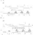
Fig. 1] Fig. 1 is a cross-sectional view of a distal end portion of a catheter according to a first embodiment of the invention. - [
Fig. 2] Fig. 2 is a cross-sectional view of a distal end portion of a catheter according to a second embodiment of the invention. - Hereinafter, preferred embodiments of the invention are provided, and are described in details with reference to the accompanying drawings. Note that, the size ratios in the drawings may be exaggerated for convenience of explanation, and may be different from the actual ratios in some cases. In the present specification, a side of a catheter to be inserted into a living body lumen is referred to as a "distal side", and a side at which the catheter is operated is referred to as a "proximal side".
- A
shaft 100 of a catheter as a first embodiment illustrated inFig. 1 includes anouter layer 11 and aninner layer 12, and includes abraid 6 therebetween in which metal wires and the like are woven together. - A plurality of metal wires are woven together to form the
braid 6 in a tubular shape so as to have gaps penetrating between an inner peripheral surface and an outer peripheral surface. Thebraid 6 includes awelding portion 10 formed in such a manner that intersection points of the metal wires mutually crossing are welded. - This is for preventing the
braid 6 from spreading out because theshaft 100 is buckled when a shaftdistal end 3 is brought into contact with a hard stenosed site or the like, and a part of the metal wires from breaking through theouter layer 11 of theshaft 100. - The
welding portion 10 is preferably positioned on a distal end of thebraid 6, but may be welded on a position at a further proximal side than the distal end of the braid and at a further distal side than a distal end of an radiopaque marker, so as to be more firmly fixed. - Alternatively, in order to reduce a level difference in physical properties between the
welding portion 10 and the shaftdistal end 3, the metal wires may protrude from thewelding portion 10 to the distal side. - The
welding portion 10 includes a welding portiondistal end 1 and a welding portionproximal end 4. In the present embodiment, thebraid 6, one of which is a single wire and the other of which is a multiple wire including two metal wires, is formed in such a manner that the single wire and the multiple wire are crossed and woven together. Note that, single wires or multiple wires may be woven together to form thebraid 6. Moreover, metal wires having different thicknesses and types may be woven together to form thebraid 6. - Examples of materials for the
braid 6 may include tungsten or stainless steel wire. The metal wire in thebraid 6 may have an arbitrary thickness, and preferably has a diameter of 5 to 100 µm, preferably 15 to 60 µm. The cross-section of the metal wire in thebraid 6 is circular, and may be elliptical, rectangular, or oval. - In the first embodiment illustrated in
Fig. 1 , the welding portiondistal end 1 is disposed at the proximal side that is distant by a distance L3 from the shaftdistal end 3. In addition, adistal end 2 of atubular marker 7 serving as an radiopaque marker is disposed at a position that is distant by a distance L1 from the welding portiondistal end 1 to the proximal side. The distance L1 is less than a distance between thedistal end 2 and aproximal end 5 of thetubular marker 7, in other words, a length L2 in a longitudinal axis direction of thetubular marker 7. Note that, the longitudinal axis direction is a direction along the longitudinal axis extending between a distal end and a proximal end of theshaft 100, for example, a direction along a central axis of a lumen of theshaft 100. - Therefore, even when the shaft
distal end 3 is brought into contact with a stenosed site, the braid distal end does not spread out between the welding portiondistal end 1 and thedistal end 2 of thetubular marker 7 by the force transmitted from the shaftdistal end 3, and the force that is transmitted from the shaftdistal end 3 is transmitted to thetubular marker 7 with high efficiency. Therefore, theshaft 100 can pass through the stenosed site without buckling. - The tubular marker 7 (radiopaque marker) is disposed at a position separated from the
welding portion 10 to the proximal side. Therefore, a position of thewelding portion 10 can be visually observed through a transparent material outside the body, and thetubular marker 7 of the catheter inside the body can also be visually recognized under the X-ray contrast. Therefore, the catheter is easily inspected when being manufactured, and can be accurately positioned when being moved forward in the unit of millimeters during surgery. In addition, a distal end of thetubular marker 7 is separated from thewelding portion 10, so that the distal end portion of the catheter becomes more flexible to improve the trackability and the branch selectivity in a complicated and thin blood vessel such as a hepatic artery. Accordingly, the catheter easily reaches a lesion area to shorten the surgery time, thereby allowing the reduction in the burden of a patient, and the reduction in labor costs. - The
tubular marker 7 having a cylindrical shape is formed by using an iridium alloy and the like. The thickness of thetubular marker 7 is 5 to 100 µm, preferably 15 to 60 µm. The length in the longitudinal axis direction of thetubular marker 7 is 0.5 to 10 mm, preferably 1 to 3 mm. Thetubular marker 7 may be fitted into theshaft 100 or embedded into theshaft 100 with a resin. - A shaft 100' according to a second embodiment illustrated in
Fig. 2 includes acoil marker 9 as the radiopaque marker in which acoil wire 8 made of metal that is recognizable under radiography is wound, and is common to that in the first embodiment other than thecoil marker 9, so that an explanation thereof is omitted. - A
distal end 2 of thecoil marker 9 is disposed at a position distant by a distance L1 from the welding portiondistal end 1 to the proximal side, and the distance L1 is less than a length L2 in the longitudinal axis direction of thecoil wire 8. - The
coil marker 9 is flexible and easily deforms, so that a distal end portion of the shaft 100' has improved trackability to the bent blood vessel. - The
coil marker 9 is formed by using a gold alloy and the like. A diameter R2 of thecoil wire 8 that forms thecoil marker 9 is 5 to 100 µm, preferably 15 to 60 µm. Thecoil wire 8 is coiled around theshaft 100. Thecoil wire 8 is wound such that a length in the longitudinal axis direction of thecoil marker 9 is 0.5 to 10 mm, preferably 1 to 3 mm. The diameter R2 of thecoil wire 8 is not specially limited, but is preferably less than the distance L1 from the welding portiondistal end 1 to thedistal end 2 of the coil marker 9 (radiopaque marker). This prevents thecoil wire 8 from becoming too thick, and thecoil marker 9 is flexible and easily deforms, so that a distal end portion of the shaft 100' has improved trackability to the bent blood vessel. - Therefore, the shaft 100' can pass through a bifurcated blood vessel of the coronary artery and a tortuous blood vessel or a branched blood vessel of the hepatic artery by following the guide wire.
- In the above, the invention has been described with the preferred embodiments, however, the invention is not limited to the embodiments, and it is needless to say that various modifications are possible without deviating from the scope of the invention.
- Note that, the application is based upon and claims the benefit of priority of the prior
Japanese Patent Application No. 2019-140688, filed on July 31, 2019 -
- 1 welding portion distal end
- 2, 2' marker distal end
- 3 shaft distal end
- 4 welding portion proximal end
- 5, 5' marker proximal end
- 6 braid
- 7 tubular marker
- 8 coil wire
- 9 coil marker
- 10 welding portion
- 11 outer layer
- 12 inner layer
- 100 shaft
- L1 distance from welding portion distal end to marker distal end
- L2 length of marker
- L3 length from shaft distal end to welding portion distal end
- R, R1 diameter of metal wire in braid
- R2 coil wire diameter
Claims (3)
- A catheter comprising a shaft including a distal end and a proximal end, whereinthe shaft includes an inner layer, an outer layer, and a braid that is disposed between the inner layer and the outer layer and includes a plurality of metal wires that are woven together,the braid includes a welding portion at a further proximal side than the distal end of the shaft that welds intersection points of the metal wires in a vicinity of a distal end of the braid, andthe shaft includes a radiopaque marker at a position separated from the welding portion to the proximal side.
- The catheter according to claim 1, wherein the radiopaque marker has a length in a longitudinal axis direction of the shaft, and the length in the longitudinal axis direction of the radiopaque marker is longer than a distance from the welding portion to a distal end of the radiopaque marker.
- The catheter according to claim 1 or 2, wherein the radiopaque marker is a coil wire, and a diameter of the coil wire is less than a distance from a distal end of the welding portion to the distal end of the radiopaque marker.
Applications Claiming Priority (2)
| Application Number | Priority Date | Filing Date | Title |
|---|---|---|---|
| JP2019140688 | 2019-07-31 | ||
| PCT/JP2020/024079 WO2021019945A1 (en) | 2019-07-31 | 2020-06-19 | Catheter |
Publications (2)
| Publication Number | Publication Date |
|---|---|
| EP3995169A1 true EP3995169A1 (en) | 2022-05-11 |
| EP3995169A4 EP3995169A4 (en) | 2022-09-28 |
Family
ID=74230245
Family Applications (1)
| Application Number | Title | Priority Date | Filing Date |
|---|---|---|---|
| EP20848033.5A Pending EP3995169A4 (en) | 2019-07-31 | 2020-06-19 | CATHETER |
Country Status (5)
| Country | Link |
|---|---|
| US (1) | US20220152351A1 (en) |
| EP (1) | EP3995169A4 (en) |
| JP (1) | JPWO2021019945A1 (en) |
| CN (1) | CN114173854B (en) |
| WO (1) | WO2021019945A1 (en) |
Family Cites Families (20)
| Publication number | Priority date | Publication date | Assignee | Title |
|---|---|---|---|---|
| US5254107A (en) * | 1991-03-06 | 1993-10-19 | Cordis Corporation | Catheter having extended braid reinforced transitional tip |
| JP3998918B2 (en) * | 1993-05-26 | 2007-10-31 | テルモ株式会社 | Guide wire |
| AU4242996A (en) * | 1994-11-23 | 1996-06-17 | Navarre Biomedical, Ltd. | Flexible catheter |
| US6648854B1 (en) * | 1999-05-14 | 2003-11-18 | Scimed Life Systems, Inc. | Single lumen balloon-tipped micro catheter with reinforced shaft |
| JP2004298361A (en) * | 2003-03-31 | 2004-10-28 | Kanai Hiroaki | Medical catheter and its manufacturing method |
| US20060030835A1 (en) * | 2004-06-29 | 2006-02-09 | Sherman Darren R | Catheter shaft tubes and methods of making |
| JP2006271901A (en) * | 2005-03-30 | 2006-10-12 | Nippon Zeon Co Ltd | Coiled contrast marker, method for manufacturing the same, and catheter |
| JP2007319594A (en) * | 2006-06-05 | 2007-12-13 | Kaneka Corp | Medical catheter tube |
| US20080125752A1 (en) * | 2006-08-09 | 2008-05-29 | Boston Scientific Scimed, Inc. | Catheter assembly having a modified reinforcement layer |
| JP4743800B2 (en) * | 2008-10-11 | 2011-08-10 | 朝日インテック株式会社 | catheter |
| JP5814530B2 (en) * | 2010-09-08 | 2015-11-17 | 株式会社カネカ | Medical catheter |
| US10130789B2 (en) * | 2011-06-30 | 2018-11-20 | Covidien Lp | Distal access aspiration guide catheter |
| JP5901183B2 (en) * | 2011-09-01 | 2016-04-06 | 株式会社グッドマン | Medical instruments |
| JP5780556B2 (en) * | 2012-08-07 | 2015-09-16 | 朝日インテック株式会社 | catheter |
| TW201438672A (en) * | 2012-12-18 | 2014-10-16 | Sumitomo Bakelite Co | Medical instrument |
| JP6080258B2 (en) * | 2013-01-30 | 2017-02-15 | 朝日インテック株式会社 | catheter |
| JP6221300B2 (en) * | 2013-03-28 | 2017-11-01 | 住友ベークライト株式会社 | Catheter and catheter operation part |
| JP6506009B2 (en) | 2013-11-22 | 2019-04-24 | パナソニック インテレクチュアル プロパティ コーポレーション オブ アメリカPanasonic Intellectual Property Corporation of America | Transmission method, reception method, transmission apparatus, and reception apparatus |
| CN107666935B (en) * | 2015-05-29 | 2021-01-05 | 柯惠有限合伙公司 | Catheter with tapered outer diameter |
| TW201825137A (en) * | 2016-11-25 | 2018-07-16 | 日商住友電木股份有限公司 | Catheter and process for producing catheter |
-
2020
- 2020-06-19 WO PCT/JP2020/024079 patent/WO2021019945A1/en not_active Ceased
- 2020-06-19 JP JP2021536656A patent/JPWO2021019945A1/ja active Pending
- 2020-06-19 EP EP20848033.5A patent/EP3995169A4/en active Pending
- 2020-06-19 CN CN202080054376.4A patent/CN114173854B/en active Active
-
2022
- 2022-01-28 US US17/587,180 patent/US20220152351A1/en active Pending
Also Published As
| Publication number | Publication date |
|---|---|
| EP3995169A4 (en) | 2022-09-28 |
| US20220152351A1 (en) | 2022-05-19 |
| WO2021019945A1 (en) | 2021-02-04 |
| CN114173854B (en) | 2024-01-12 |
| JPWO2021019945A1 (en) | 2021-02-04 |
| CN114173854A (en) | 2022-03-11 |
Similar Documents
| Publication | Publication Date | Title |
|---|---|---|
| US10933220B2 (en) | Balloon catheter | |
| JP5381703B2 (en) | Thrombus aspiration catheter | |
| CN102395400B (en) | Medical guide wire | |
| EP1985244A2 (en) | Interventional medical device system having a slotted section and radiopaque marker and method of making the same | |
| US8777873B2 (en) | Wire guide having a rib for coil attachment | |
| EP2943244B1 (en) | Coronary guidewire | |
| US20240075242A1 (en) | Catheter | |
| CN111067590A (en) | Catheter tube | |
| JP6722350B2 (en) | catheter | |
| US20220152351A1 (en) | Catheter | |
| CN111163832B (en) | Guide wire | |
| WO2020250934A1 (en) | Catheter | |
| JP6735910B2 (en) | catheter | |
| JP2006271901A (en) | Coiled contrast marker, method for manufacturing the same, and catheter | |
| JPWO2018193598A1 (en) | catheter | |
| US20250242133A1 (en) | Distal stabilizer and method for imaging distal stabilizer | |
| EP3659665A1 (en) | Balloon catheter | |
| EP4205790B1 (en) | Guide wire | |
| US9014816B2 (en) | Medical lead with filler layer | |
| JP6844000B2 (en) | catheter | |
| WO2024024349A1 (en) | Dilator | |
| WO2022249413A1 (en) | Catheter | |
| JP2024084369A (en) | catheter | |
| CN117396245A (en) | Guide wire | |
| JP2013013591A (en) | Marker and catheter |
Legal Events
| Date | Code | Title | Description |
|---|---|---|---|
| STAA | Information on the status of an ep patent application or granted ep patent |
Free format text: STATUS: THE INTERNATIONAL PUBLICATION HAS BEEN MADE |
|
| PUAI | Public reference made under article 153(3) epc to a published international application that has entered the european phase |
Free format text: ORIGINAL CODE: 0009012 |
|
| STAA | Information on the status of an ep patent application or granted ep patent |
Free format text: STATUS: REQUEST FOR EXAMINATION WAS MADE |
|
| 17P | Request for examination filed |
Effective date: 20220204 |
|
| AK | Designated contracting states |
Kind code of ref document: A1 Designated state(s): AL AT BE BG CH CY CZ DE DK EE ES FI FR GB GR HR HU IE IS IT LI LT LU LV MC MK MT NL NO PL PT RO RS SE SI SK SM TR |
|
| A4 | Supplementary search report drawn up and despatched |
Effective date: 20220831 |
|
| RIC1 | Information provided on ipc code assigned before grant |
Ipc: A61M 25/01 20060101ALI20220825BHEP Ipc: A61M 25/098 20060101ALI20220825BHEP Ipc: A61M 25/00 20060101AFI20220825BHEP |
|
| DAV | Request for validation of the european patent (deleted) | ||
| DAX | Request for extension of the european patent (deleted) | ||
| STAA | Information on the status of an ep patent application or granted ep patent |
Free format text: STATUS: EXAMINATION IS IN PROGRESS |
|
| 17Q | First examination report despatched |
Effective date: 20250812 |