EP3993552A1 - Wireless terminal and method therefor - Google Patents
Wireless terminal and method therefor Download PDFInfo
- Publication number
- EP3993552A1 EP3993552A1 EP20882132.2A EP20882132A EP3993552A1 EP 3993552 A1 EP3993552 A1 EP 3993552A1 EP 20882132 A EP20882132 A EP 20882132A EP 3993552 A1 EP3993552 A1 EP 3993552A1
- Authority
- EP
- European Patent Office
- Prior art keywords
- pdu session
- new
- amf
- release
- session
- Prior art date
- Legal status (The legal status is an assumption and is not a legal conclusion. Google has not performed a legal analysis and makes no representation as to the accuracy of the status listed.)
- Withdrawn
Links
- 238000000034 method Methods 0.000 title claims description 156
- 230000006870 function Effects 0.000 claims description 65
- 230000004044 response Effects 0.000 claims description 51
- 230000000977 initiatory effect Effects 0.000 claims description 11
- 238000007726 management method Methods 0.000 description 75
- 101100348958 Caenorhabditis elegans smf-3 gene Proteins 0.000 description 64
- 238000012545 processing Methods 0.000 description 24
- 230000005540 biological transmission Effects 0.000 description 20
- 230000001413 cellular effect Effects 0.000 description 12
- 230000011664 signaling Effects 0.000 description 12
- 238000010586 diagram Methods 0.000 description 11
- 238000004891 communication Methods 0.000 description 7
- 230000008569 process Effects 0.000 description 7
- 230000001960 triggered effect Effects 0.000 description 6
- 230000008901 benefit Effects 0.000 description 2
- 238000006243 chemical reaction Methods 0.000 description 2
- 238000004590 computer program Methods 0.000 description 2
- 230000003068 static effect Effects 0.000 description 2
- 101150119040 Nsmf gene Proteins 0.000 description 1
- 230000006978 adaptation Effects 0.000 description 1
- 230000003321 amplification Effects 0.000 description 1
- 230000010267 cellular communication Effects 0.000 description 1
- 230000008859 change Effects 0.000 description 1
- 238000013144 data compression Methods 0.000 description 1
- 238000013523 data management Methods 0.000 description 1
- 238000000354 decomposition reaction Methods 0.000 description 1
- 230000006837 decompression Effects 0.000 description 1
- 238000001514 detection method Methods 0.000 description 1
- 230000000694 effects Effects 0.000 description 1
- 230000010354 integration Effects 0.000 description 1
- 238000013507 mapping Methods 0.000 description 1
- 238000010295 mobile communication Methods 0.000 description 1
- 238000012986 modification Methods 0.000 description 1
- 230000004048 modification Effects 0.000 description 1
- 238000003199 nucleic acid amplification method Methods 0.000 description 1
- 230000011218 segmentation Effects 0.000 description 1
- 238000012546 transfer Methods 0.000 description 1
Images









Classifications
-
- H—ELECTRICITY
- H04—ELECTRIC COMMUNICATION TECHNIQUE
- H04W—WIRELESS COMMUNICATION NETWORKS
- H04W76/00—Connection management
- H04W76/10—Connection setup
- H04W76/11—Allocation or use of connection identifiers
-
- H—ELECTRICITY
- H04—ELECTRIC COMMUNICATION TECHNIQUE
- H04W—WIRELESS COMMUNICATION NETWORKS
- H04W76/00—Connection management
- H04W76/30—Connection release
-
- H—ELECTRICITY
- H04—ELECTRIC COMMUNICATION TECHNIQUE
- H04W—WIRELESS COMMUNICATION NETWORKS
- H04W76/00—Connection management
- H04W76/30—Connection release
- H04W76/34—Selective release of ongoing connections
-
- H—ELECTRICITY
- H04—ELECTRIC COMMUNICATION TECHNIQUE
- H04W—WIRELESS COMMUNICATION NETWORKS
- H04W80/00—Wireless network protocols or protocol adaptations to wireless operation
- H04W80/08—Upper layer protocols
- H04W80/10—Upper layer protocols adapted for application session management, e.g. SIP [Session Initiation Protocol]
Definitions
- the present disclosure relates to a cellular network and, in particular, to release and establishment of a connectivity service between UE and an external data network.
- the 5G system connects user equipment (UE) to an external data network (Data Network (DN)).
- connectivity services between the UE and the DN are supported by Protocol Data Unit (PDU) sessions.
- a PDU session is an association between the UE and the DN and is used to provide a PDU connectivity service (i.e., exchange of PDUs between the UE and the DN).
- a PDU session is established between the UE and a User Plane Function (UPF) (i.e., PDU session anchor) to which the DN is connected.
- UPF User Plane Function
- a PDU session consists of a tunnel (N9 tunnel) in the 5G core network (5GC), a tunnel (N3 tunnel) between the 5GC and an Access Network (AN), and one or more radio bearers.
- SMF Session Management Function
- the SMF sends and receives SM signalling messages (NAS-SM messages, N1 SM messages) to and from the Non-Access Stratum (NAS)-SM layer of a UE via a network function (NF) service (i.e., communication service with a UE) provided by an Access and Mobility Management Function (AMF).
- NAS-SM messages Non-Access Stratum
- N1 SM messages Non-Access Stratum
- NF network function
- AMF Access and Mobility Management Function
- the AMF terminates a single signalling connection (i.e., N1 NAS signalling connection) with a UE.
- N1 NAS signalling connection i.e., N1 NAS signalling connection
- the Single N1 NAS signalling connection is used for both Registration and Connection Managements (RM/CM) for the UE, and SM-related messages and procedures.
- RM/CM Registration and Connection Managements
- a PDU session is established in response to a request from a UE or a network.
- a PDU Session ID is used to specify a PDU session.
- a PDU Session ID is an identifier that is generated by a UE and is unique among PDU Sessions that this UE deals with.
- a PDU Session ID assigned to a PDU session to be newly generated shall not be the same as any of the IDs of existing PDU sessions.
- the term "PDU Session ID" used herein may indicate the value of a PDU Session ID generated for a PDU session.
- Non-Patent Literature 1 (3GPP TS 23.502) and Non-Patent Literature 2 (3GPP TS 24.501) specify a PDU session establishment procedure and a PDU Session release procedure. More specifically, the PDU session establishment procedure is described, for example, in clause 4.3.2.2 of Non-Patent Literature 1 and clause 6.4.1 of Non-Patent Literature 2. The PDU Session release procedure is described, for example, in clause 4.3.4.2 of Non-Patent Literature 1 and clauses 6.3.3 and 6.4.3 of Non-Patent Literature 2.
- the UE receives a NAS message containing a PDU Session Release Command from the AMF.
- the PDU Session Release Command is SM signalling (N1 SM message) sent from the SMF to the UE via the AMF in order to instruct the UE to release the PDU session.
- the UE sends a NAS message containing PDU Session Release Complete to the AMF in order to acknowledge the PDU Session Release Command.
- This NAS message contains the PDU Session ID of the PDU session to be released, and an N1 SM container (PDU Session Release Complete).
- the N1 SM container (PDU Session Release Complete) is transmitted to the SMF via the AMF.
- the PDU Session Release Complete may instead be called PDU Session Release Ack.
- the SMF performs (or invokes) an Nsmf_PDUSession_SMContextStatusNotify service operation to notify the AMF that the SM context for the PDU session is to be released.
- the Nsmf_PDUSession_SMContextStatusNotify is one of the NF services provided by the SMF.
- An Nsmf_PDUSession_SMContextStatusNotify is used by the SMF to notify its consumer (e.g., AMF) of the status of the SM context regarding a PDU session.
- the AMF releases a UE context (i.e., PDU session level context) related to the PDU session in response to the Nsmf_PDUSession_SMContextStatusNotify message.
- PDU session level context managed by the AMF includes associations among the SMF information (e.g., SMF ID), PDU Session ID, and Data Network Name (DNN).
- the SMF performs (or invokes) an Nudm_UECM_Deregistration service operation, including the Data Network Name (DNN) and PDU Session ID, to release the context regarding the PDU session to be released.
- the Nudm_UECM_Deregistration is one of the NF services provided by a Unified Data Management (UDM).
- An NF consumer e.g., SMF
- the UDM removes the association between the SMF identity and the associated DNN and PDU Session ID.
- Non-Patent Literature 1 after the UE sends PDU Session Release Complete (SM signalling) to the SMF via the AMF, the SMF releases the context (resources) in the 5GC regarding this PDU session (or removes this context from the 5GC) while cooperating with the AMF and the UDM.
- PDU Session Release Complete SM signalling
- the UE may be able to request the 5GC to establish a new PDU session just after sending PDU Session Release Complete (SM signalling).
- the UE may be able to use the PDU Session ID associated with a PDU session that has just been released for a new PDU session to be established. This is because, in the UE's point view, it can be considered that PDU Session ID is considered to be no longer associated with any of the existing PDU sessions.
- the 5GC may receive a PDU session establishment request from the UE indicating the same PDU Session ID as that of the PDU session to be released. In this case, the 5GC may not be able to correctly distinguish the new PDU session to be established from the PDU session to be released. This is because, PDU Session IDs generated (or determined) by the UE are used in both the management of PDU sessions by the SMF and the management of the UE context (PDU Session level context) related to PDU sessions by the AMF.
- an unfavorable scenario including the following steps (1)-(3) may occur.
- step (1) a UE-initiated PDU Session release procedure is performed to release an existing PDU session that is managed by SMF #1 and is associated with PDU Session ID #1.
- the UE sends a NAS message containing PDU Session ID #1 and an N1 SM container (PDU Session Release Complete) to the AMF.
- PDU Session Release Complete PDU Session Release Complete
- step (2) immediately after the transmission of the PDU Session Release Complete, the UE selects PDU Session ID #1 to establish a new PDU session and sends a NAS message for requesting establishment of a new PDU session to the AMF.
- This NAS message contains PDU Session ID #1, a Request type indicating "initial request” or "initial emergency request", and an N1 SM container (PDU Session Establishment Request).
- the AMF selects, for example, SMF #2 for a new PDU session and sends an Nsmf_PDUSession_CreateSMContext Request to the SMF #2.
- This Nsmf_PDUSession_CreateSMContext Request contains PDU Session ID #1 and the N1 SM container (PDU Session Establishment Request).
- the Nsmf_PDUSession_CreateSMContext service operation is one of the NF services provided by an SMF.
- the AMF as an NF consumer uses the Nsmf_PDUSession_CreateSMContext to create an AMF-SMF association to support a PDU session.
- step (3) while the procedure for establishing a new PDU session related to Step (2) is taking place, SMF #1 sends an Nsmf_PDUSession_SMContextStatusNotify message to the AMF indicating that the SM context for the existing PDU session is to be released.
- the AMF may accidentally remove the UE context (PDU Session level context) created for the new PDU session.
- a problem may occur in the case where the UE initiates the PDU session establishment procedure before the PDU session release is successfully completed within the 5GC. Specifically, there is a risk of conflict or collision between an uncompleted PDU session release and a new PDU session establishment that are associated with the same PDU Session ID. Such a conflict (or a situation where such a conflict is occurring) can be referred to as "PDU Session ID duplicated".
- This problem may occur not only in the case where the UE requests the SMF for a PDU session release (i.e., in the UE-initiated PDU Session release procedure). Specifically, this problem may occur also in the case where a Policy Control Function (PCF) requests the SMF for a PDU session release.
- PCF Policy Control Function
- This problem can also occur in the case where an Access Network (AN) requests the SMF for a PDU session release, in other words, the AN notifies the SMF of a release of the resources related to a PDU session and the SMF decides to release the PDU session based on the notification. Furthermore, this problem may occur in the case where the SMF decides to release a PDU session and initiates the PDU session release.
- One of the objects to be attained by example embodiments disclosed herein is to provide apparatuses, methods, and programs that contribute to avoiding a conflict (or collision) between an uncompleted PDU session release and a new PDU session establishment that are associated with the same PDU Session ID. It should be noted that this object is merely one of the objects to be attained by the example embodiments disclosed herein. Other objects or problems and novel features will be made apparent from the following description and the accompanying drawings.
- an AMF node includes at least one memory and at least one processor coupled to the at least one memory.
- the at least one processor is configured to, in response to receiving a first control message containing a first Session Management (SM) container from a Session Management Function (SMF), send a first Non-Access Stratum (NAS) message containing the first SM container to a radio terminal.
- the first SM container contains a PDU Session Release Command message sent from the SMF to the radio terminal in order to indicate release of a first PDU session associated with a first Protocol Data Unit (PDU) Session ID.
- the at least one processor is further configured to, after sending the first NAS message to the radio terminal, send to the radio terminal a second NAS message to indicate that the first PDU Session ID can be assigned to another PDU session different from the first PDU session.
- a method for an AMF node includes the following steps (a) and (b):
- a radio terminal includes at least one memory and at least one processor coupled to the at least one memory.
- the at least one processor is configured to receive from an Access and Mobility Management Function (AMF) a first Non-Access Stratum (NAS) message containing a first Session Management (SM) container.
- the first SM container contains a PDU Session Release Command message sent from a Session Management Function (SMF) to the radio terminal in order to indicate release of a first PDU session associated with a first Protocol Data Unit (PDU) Session ID.
- the at least one processor is further configured to, after receiving the first NAS message, receive from the AMF a second NAS message indicating that the first PDU Session ID can be assigned to another PDU session different from the first PDU session.
- a method for a radio terminal includes the following steps (a) and (b):
- a radio terminal includes at least one memory and at least one processor coupled to the at least one memory.
- the at least one processor is configured to receive from an Access and Mobility Management Function (AMF) a first Non-Access Stratum (NAS) message containing a first Session Management (SM) container .
- the first SM container contains a PDU Session Release Command message sent from a Session Management Function (SMF) to the radio terminal in order to indicate release of a first PDU session associated with a first Protocol Data Unit (PDU) Session ID.
- the at least one processor further receives a second NAS message from the AMF after receiving the first NAS message, and the at least one processor is allowed to assign the first PDU Session ID by receiving the second NAS message.
- a method of a radio terminal includes the following steps (a) and (b):
- a radio terminal includes at least one memory and at least one processor coupled to the at least one memory.
- the at least one processor is configured to, upon receiving from an Access and Mobility Management Function (AMF) a first control message that contains a Session Management (SM) container including a PDU Session Release Command, be unable or not allowed to assign a PDU Session ID specified by the PDU Session Release Command to another PDU session other than a PDU session specified by the PDU Session Release Command.
- AMF Access and Mobility Management Function
- SM Session Management
- the at least one processor is configured to, by receiving from an Access and Mobility Management Function (AMF) a first control message that contains a Session Management (SM) container including a NAS Notify, be allowed to assign a PDU Session ID specified by the NAS Notify to the other PDU session.
- AMF Access and Mobility Management Function
- SM Session Management
- a method for a radio terminal includes the following steps (a) and (b):
- an AMF node includes at least one memory and at least one processor coupled to the at least one memory.
- the at least one processor is configured to determine whether a new PDU Session ID associated with a new Protocol Data Unit (PDU) session requested from a radio terminal is the same as a first PDU Session ID associated with an existing first PDU session that has not been successfully released.
- the at least one processor is further configured to, if the new PDU Session ID is the same as the first PDU Session ID, perform a procedure for avoiding a conflict between establishment of the new PDU session and release of the first PDU session.
- PDU Protocol Data Unit
- a method for an AMF node includes the following steps (a) and (b):
- an SMF node includes at least one memory and at least one processor coupled to the at least one memory.
- the at least one processor is configured to receive a first NAS message for establishment of a new Protocol Data Unit (PDU) session from a radio terminal via an Access and Mobility Management Function (AMF).
- the at least one processor is further configured to, if a new PDU Session ID associated with the new PDU session is the same as a first PDU Session ID associated with an existing first PDU session that has not been successfully released, send a second NAS message indicating rejection of establishment of the new PDU session to the radio terminal via the AMF.
- PDU Protocol Data Unit
- AMF Access and Mobility Management Function
- a method for an SMF node includes the following steps (a) and (b):
- a radio terminal includes at least one memory and at least one processor coupled to the at least one memory.
- the at least one processor is configured to, for a first period associated with release of a first Protocol Data Unit (PDU) session, assign to a new PDU session to be established a PDU Session ID different from a first PDU Session ID that was assigned to the first PDU session.
- PDU Protocol Data Unit
- a method for a radio terminal includes the following steps (a) and (b):
- a radio terminal includes at least one memory and at least one processor coupled to the at least one memory.
- the at least one processor is configured to assign a Protocol Data Unit (PDU) Session ID that is different from most recently used one or more PDU Session IDs to a new PDU session to be established.
- PDU Protocol Data Unit
- a method for a radio terminal includes the following steps (a) and (b):
- a radio terminal includes at least one memory and at least one processor coupled to the at least one memory.
- the at least one processor is configured to, in at least a first attempt to establish a new Protocol Data Unit (PDU) session performed after release of a first PDU session, assign to the new PDU session a PDU Session ID different from a first PDU Session ID that was assigned to the first PDU session.
- PDU Protocol Data Unit
- a method for a radio terminal includes the following steps (a) and (b):
- a program includes instructions (software codes) that, when loaded into a computer, cause the computer to perform the method according to the above-described second, fourth, sixth, eighth, tenth, twelfth, fourteenth, sixteenth, or eighteenth aspect.
- each of the example embodiments described below may be used individually, or two or more of the example embodiments may be appropriately combined with one another. These example embodiments include novel features different from each other. Accordingly, these example embodiments contribute to attaining objects or solving problems different from one another and also contribute to obtaining advantages different from one another.
- 5G system 5G system
- these example embodiments may be applied to other cellular communication systems that support session (or connection) establishment and release procedures similar to the 5GS.
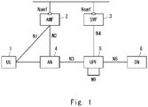
- Fig. 1 shows a configuration example of a cellular network (i.e., 5GS) according to this example embodiment.
- Each of the elements shown in Fig. 1 is a network function and provides an interface defined by the 3rd Generation Partnership Project (3GPP).
- 3GPP 3rd Generation Partnership Project
- Each of the elements (network functions) shown in Fig. 1 may be implemented as, for example, a network element on a dedicated hardware, as a software instance running on the dedicated hardware, or as a virtualization function instantiated on an application platform.
- a radio terminal (i.e., UE) 1 uses 5G connectivity services and communicates with an external data network (DN) 6. More specifically, the UE 1 is connected to an access network (i.e., 5GAN) 4 and communicates with the external data network (DN) 6 via a User Plane Function (UPF) 5 in a core network (i.e., 5GC).
- the AN 4 includes one or both of a Next Generation Radio Access Network (NG-RAN) and a non-3GPP AN.
- the UPF 5 may include multiple UPFs that are interconnected.
- the UE 1 establishes one or more PDU sessions between the UE 1 and the UPF 5 (i.e., UPF as a PDU session anchor connected to the DN 6). While not shown in Fig. 1 , the UE 1 may establish multiple PDU sessions with multiple UPFs (PDU session anchors) 5 in order to concurrently access multiple DNs 6.
- the AMF 2 is one of the network functions in the 5GC Control Plane.
- the AMF 2 provides the termination of a RAN Control Plane (CP) interface (i.e., N2 interface).
- the AMF 2 terminates a single signalling connection (i.e., N1 NAS signalling connection) with the UE 1 and provides registration management, connection management, and mobility management.
- the AMF 2 provides NF services to NF consumers (e.g., other AMFs, SMF, and PCF) on a service-based interface (i.e., Namf interface).
- the NF services provided by the AMF 2 include a communication service (Namf_Communication).
- the communication service allows NF consumers (e.g., SMF) to communicate with the UE 1 or the AN 4 via the AMF 2.
- the SMF 3 is one of the network functions in the 5GC Control Plane.
- the SMF 3 manages PDU sessions.
- the SMF 3 sends and receives SM signalling messages (NAS-SM messages, N1 SM messages) to and from the NAS-SM layer of the UE 1 via the communication service provided by the AMF 2.
- the SMF 3 provides NF services to NF consumers (e.g., AMF, other SMFs) on a service-based interface (i.e., Nsmf interface).
- the NF services provided by the SMF 3 include a PDU session management service (Nsmf_PDUSession). This NF services allows NF consumers (e.g., AMF) to handle PDU sessions.
- the configuration example in Fig. 1 shows only typical NFs for convenience of explanation.
- the cellular network according to this example embodiment may include other NFs not shown in Fig. 1 , such as a UDM, a PCF, an Authentication Server Function (AUSF), and a Network Slice Selection Function (NSSF).
- a UDM User Data Management Function
- PCF Packet Control Function
- AUSF Authentication Server Function
- NSSF Network Slice Selection Function
- Fig. 2 shows one example of an operation regarding release of a first PDU session associated with PDU Session ID #1.
- the UE 1 receives a PDU Session Release Command indicating release of the first PDU session associated with PDU Session ID #1 from the SMF 3 via the AMF 2 (Step 203), and then further receives an additional NAS message (e.g., NAS Notify) associated with PDU Session ID #1 from the AMF 2 or from the SMF 3 via the AMF 2 (Step 205).
- NAS message e.g., NAS Notify
- the additional NAS message may explicitly or implicitly notify the UE 1 that the Session Management (SM) context for the first PDU session (PDU Session ID #1) has been successfully released in the 5GC. Additionally or alternatively, the additional NAS message (Step 205) may explicitly or implicitly allow the UE 1 to assign PDU Session ID #1 to a new PDU session different from the first PDU session.
- SM Session Management
- the UE 1 may recognize that PDU Session ID #1 can be assigned to a new PDU session different from the first PDU session in response to the additional NAS message (Step 205).
- the UE 1 may operate so as not to assign PDU Session ID #1 to a new PDU session to be established until it receives an additional NAS message (Step 205) after sending a PDU Session Release Complete message towards the SMF 3 in response to the PDU Session Release Command message (Step 203).
- the UE 1 may operate so as to assign a PDU Session ID different from PDU Session ID #1 to a newly established PDU session at least until it receives an additional NAS message (Step 205).
- Step 201 the UE 1 establishes a first PDU session associated with PDU Session ID #1.
- Step 201 may be performed in accordance with the existing PDU session establishment procedure (see, for example, clause 4.3.2.2 of Non-Patent Literature 1).
- Steps 202-205 are related to release of the first PDU session.
- the SMF 3 sends an N1 SM container containing a PDU Session Release Command to the AMF 2.
- the PDU Session Release Command is sent from the SMF 3 to the UE 1 to indicate the release of the first PDU session associated with PDU Session ID #1.
- the SMF 3 sends the N1 SM container containing the PDU Session Release Command to the AMF 2 using an Nsmf_PDUSession_UpdateSMContext Response message.
- the SMF 3 sends the N1 SM container containing the PDU Session Release Command to the AMF 2 using an Nsmf_PDUSession_UpdateSMContext Response message.
- the SMF 3 sends the N1 SM container containing the PDU Session Release Command to the AMF 2 using an Namf_Communication_N1N2MessageTransfer message.
- Step 203 the AMF 2 sends a NAS message including the N1 SM container including the PDU Session Release Command to the UE 1 via the AN 4.
- Steps 202 and 203 may be similar to the corresponding steps included in the existing PDU Session release procedure (see, for example, clause 4.3.4.2 of Non-Patent Literature 1).
- the UE 1 may send the PDU Session Release Complete message towards the SMF 3 in response to the PDU Session Release Command (Step 203) prior to receiving the additional NAS message (Step 205). More specifically, the UE 1 may send to the AMF 2 a NAS message including an N1 SM container containing the PDU Session Release Complete message to the SMF 3.
- the PDU Session Release Complete message indicates acceptance of the release of the PDU session identified by the PDU Session Release Command.
- the PDU Session Release Complete message may be referred to as a PDU Session Release Ack message.
- Step 204 the SMF 3 invokes an Nsmf_PDUSession_SMContextStatusNotify service operation to notify the AMF 2 that the SM context for the first PDU session is to be released.
- the Nsmf_PDUSession_SMContextStatusNotify message (Step 204) notifies the AMF 2 that the status of the SM context regarding the first PDU session associated with PDU Session ID #1 is "release".
- the AMF 2 releases the UE context (i.e., PDU session level context) related to the first PDU session.
- the PDU session level context managed by the AMF 2 includes, for example, an association among the SMF information (e.g., SMF ID), PDU Session ID, and DNN.
- Step 205 the AMF 2 sends the additional NAS message (e.g., NAS Notify) to the UE 1 in response to receiving the Nsmf_PDUSession_SMContextStatusNotify message (Step 204).
- the additional NAS message indicates PDU Session ID #1.
- the AMF 2 may send the additional NAS message (Step 205) before, after, or concurrently with the release of the UE context related to the first PDU session (i.e., PDU session level context).
- the UE 1 receives the additional NAS message (Step 205) after receiving the NAS message containing the PDU Session Release Command (Step 203).
- the UE 1 may recognize in response to the additional NAS message (Step 205) that PDU Session ID #1 can be assigned to a new PDU session different from the first PDU session.
- the UE 1 may operate so as to assign a PDU Session ID different from PDU Session ID #1 to a new PDU session to be established, at least until it receives the additional NAS message (Step 205).
- the SMF 3 may send the additional NAS message (Step 205) to the UE 1 at any suitable time.
- the SMF 3 may send the additional NAS message (Step 205) to the UE 1 after the state in which the first PDU session associated with PDU Session ID #1 has been established as shown in Step 201.
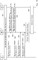
- Fig. 3 shows in detail a specific example of the PDU Session release procedure initiated by the UE 1 according to this example embodiment.
- the UE 1 establishes a first PDU session associated with PDU Session ID #1.
- Step 301 may be performed according to the existing PDU session establishment procedure (see, for example, clause 4.3.2.2 of Non-Patent Literature 1).
- Steps 302-312 are related to release of the first PDU session (PDU Session ID #1). Except for Steps 310 and 311, Steps 302-309 and 312 may be similar to the corresponding steps included in the existing PDU Session release procedure (see, for example, clause 4.3.4.2 of Non-Patent Literature 1). Steps 304 and 305 correspond to Steps 202 and 203 in Fig. 2 and Steps 309 and 310 correspond to Steps 204 and 205 in Fig. 2 .
- the UE 1 initiates a PDU Session release procedure to request the release of the first PDU session associated with PDU Session ID #1. Specifically, the UE 1 sends a PDU Session Release Request to the SMF 3 via the AMF 2. More specifically, the UE 1 sends a NAS message, containing PDU Session ID #1 and an N1 SM container (PDU Session Release Request (PDU Session ID #1)), to the AMF 2.
- the AMF 2 invokes an Nsmf_PDUSession_UpdateSMContext service operation and forwards the N1 SM container to the SMF 3 that corresponds to PDU Session ID #1.
- the SMF 3 releases the IP address and Prefix(es) assigned to the first PDU session, and releases the corresponding user plane resources. Then, in Step 304, the SMF 3 responds to the AMF 2 with an Nsmf_PDUSession_UpdateSMContext response.
- the Nsmf_PDUSession_UpdateSMContext response contains an N1 SM container (PDU Session Release Command (PDU Session ID #1)).
- the AMF 2 sends the N1 SM container (PDU Session Release Command (PDU Session ID #1)) received from the SMF 3 to the UE 1. Specifically, the AMF 2 sends a NAS message to the UE 1 that contains PDU Session ID #1 and the N1 SM container. This NAS message reaches the UE 1 via the AN 4.
- Step 306 the UE 1 sends a NAS message containing PDU Session Release Complete to the AMF 2 to acknowledge the PDU Session Release Command.
- This NAS message contains the PDU Session ID of the PDU session to be released, and the N1 SM container (PDU Session Release Complete).
- the AMF 2 invokes an Nsmf_PDUSession_UpdateSMContext service operation and forwards the N1 SM container to the SMF 3 corresponding to PDU Session ID #1.
- Step 308 the SMF 3 responds to the AMF 2 with an Nsmf_PDUSession_UpdateSMContext response.
- Step 309 the SMF 3 invokes an Nsmf_PDUSession_SMContextStatusNotify service operation to notify the AMF 2 that the SM context for the first PDU session is to be released.
- the Nsmf_PDUSession_SMContextStatusNotify message (Step 309) notifies the AMF 2 that the status of the SM context regarding the first PDU session associated with PDU Session ID #1 is "release".
- the AMF 2 releases the PDU session level context related to the first PDU session.
- the AMF 2 sends an additional NAS message (e.g., NAS Notify) to the UE 1 in response to the reception of the Nsmf_PDUSession_SMContextStatusNotify message (Step 309).
- the additional NAS message indicates PDU Session ID #1.
- the AMF 2 may send the additional NAS message (Step 310) before, after, or concurrently with the release of the PDU session level context related to the first PDU session.
- the UE 1 is allowed to assign PDU Session ID #1 to a PDU session different from the first PDU session.
- Step 311 the UE 1 responds to the AMF 2 with a NAS message (e.g., NAS Notify Ack).
- Step 311 may be omitted.
- the AMF 2 responds to the SMF 3 with Nsmf_PDUSession_SMContextStatusNotify Ack.
- the AMF 2 may perform Step 312 in response to the reception of the NAS message in Step 311.
- the AMF 2 may perform Step 312 regardless of the reception of the NAS message in Step 311.
- the AMF 2 may perform Step 312 prior to Step 311.
- the procedures shown in Figs. 2 and 3 may be modified, for example, as follows.
- the SMF 3 may send an N1 SM container destined for the UE 1 to the AMF 2 using an Namf_Communication_N1N2MessageTransfer message before or after the Nsmf_PDUSession_SMContextStatusNotify service operation (Steps 204 and 309).
- the AMF 2 may send the additional NAS message containing that N1 SM container (Steps 205 and 310) to the UE 1.
- the N1 SM container may contain, for example, a new SM signalling message for notifying the UE 1 that the SM context for one PDU session is to be released.
- the transmission of the additional NAS message by the AMF 2 (Steps 205 and 310) may be triggered by a control message other than Nsmf_PDUSession_SMContextStatusNotify.
- the AMF 2 in a PDU Session release procedure, sends an additional NAS message (e.g., Steps 205 and 310) to the UE 1 in addition to the NAS message containing the PDU Session Release Command.
- This for example, enables the UE 1 not to assign PDU Session ID #1 to a new PDU session to be established at least until it receives the additional NAS message (e.g., Steps 205 and 310).
- this example embodiment can contribute to avoiding a conflict (interference, collision, or PDU Session ID duplicated) between an uncompleted PDU session release and a new PDU session establishment that are associated with the same PDU Session ID.
- the configuration example of a cellular network according to this example embodiment may be similar to the example shown in Fig. 1 .
- the UE 1 may notify the AMF 2 that the UE 1 supports the PDU Session release procedure described in the first example embodiment (hereinafter also referred to as the enhanced PDU Session release procedure).
- the UE 1 may send capability information to the AMF 2 indicating that the UE 1 has the capability of handling the enhanced PDU Session release procedure.
- the AMF 2 may determine whether to use the enhanced PDU Session release procedure for the UE 1 depending on whether the AMF 2 has received the capability information from the UE 1.
- the AMF 2 may notify the UE 1 that the AMF 2 will apply the enhanced PDU Session release procedure, depending on whether it has received the capability information from the UE 1.
- This enhanced PDU Session release procedure may be the normal PDU Session release procedure including a procedure for sending an additional NAS message (e.g., Step 205 or Step 310 in the first example embodiment) to the UE 1.
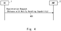
- the UE 1 may send such capability information (e.g., "Release with Notify Handling Capability") to the AMF 2 in a registration procedure of the UE 1 to the 5GS.
- the UE 1 may include the capability information in a Registration Request message (Step 401). This capability information may be added to an existing information element (e.g., "5GMM capability” information element).
- the AMF 2 may inform the UE 1 of the use of the enhanced PDU Session release procedure.
- the AMF 2 may include in a Registration Accept message an information element indicating the use of the enhanced PDU Session release procedure.
- the name of the information element may be, for example, "Release with Notify Handling Capability", “Release with Notify Handling Adapted”, or "Duplicated PDU Session ID detection capability supported”.
- An existing information element e.g., "5GS network feature support” information element
- the AMF 2 may consider one or both of the capability of the SMF 3 connected to the UE 1 and the capability of the SMF 3 that is expected to be connected to the UE 1 when determining whether to set the information element indicating the use of the enhanced PDU Session release procedure in the Registration Accept message.
- the UE 1 if the UE 1 has received information indicating the use of the (enhanced) PDU Session release procedure from the AMF 2 via the Registration Accept message, the UE 1 cannot or is not allowed to assign PDU Session ID #1 to a PDU session other than the first PDU session even after receiving the N1 SM container (PDU Session Release Command (PDU Session ID #1)).
- the procedure of this example embodiment allows the 5GS (AMF 2) to provide connectivity services to UEs that support the enhanced PDU Session release procedure and UEs that do not support it.
- This procedure may be used to inform the AMF 2 of the support of the enhanced PDU Session release procedure according to example embodiments described below.
- Step 501 the AMF 2 receives a PDU Session Establishment Request message from the UE 1. Specifically, the AMF 2 receives a NAS message containing a PDU Session ID, a Request type indicating "initial request" or "initial emergency request", and an N1 SM container (PDU Session Establishment Request) from the UE 1.
- PDU Session Establishment Request PDU Session Establishment Request
- the AMF 2 determines whether the new PDU Session ID associated with the new PDU session requested from the UE 1 is the same as the PDU Session ID of an existing PDU session that has not been successfully released.
- the AMF 2 may perform this determination when the Request type contained in the NAS message from the UE 1 indicates "initial request” or "initial emergency request". More specifically, when the Request type contained in the NAS message from the UE 1 indicates “initial request” or "initial emergency request" and the AMF 2 holds a valid PDU session level context associated with the PDU Session ID contained in this NAS message, the AMF 2 may determine that the new PDU Session ID is the same as that of the existing PDU session.
- Step 503 if the new PDU Session ID is the same as that of the existing PDU session, the AMF 2 performs a procedure to avoid a conflict between the establishment of the new PDU session and the release of the existing PDU session.
- the procedure to avoid a conflict There are several possible solutions for the procedure to avoid a conflict. In this example embodiment, one or some solutions will be described. Other solutions will be described in subsequent example embodiments.
- the AMF 2 may perform the procedure shown in Fig. 6 .
- Steps 601 and 602 are similar to Steps 501 and 502 in Fig. 5 .
- the AMF 2 suspends the establishment of the new PDU session until the release of the existing PDU session is completed. More specifically, the AMF 2 may refrain from sending the NAS message for establishing the new PDU session (i.e., PDU Session Establishment Request message) to the SMF 3 until the release of the existing PDU session is completed.
- Fig. 7 shows in detail a specific example of the PDU Session release procedure initiated by the UE 1 according to this example embodiment.
- Steps 701-706 are similar to Steps 301-306 in Fig. 3 .
- the UE 1 establishes a first PDU session associated with PDU Session ID #1.
- Step 301 may be performed according to the existing PDU session establishment procedure (see, for example, clause 4.3.2.2 of Non-Patent Literature 1).
- Steps 702-706 are related to the release of the first PDU session (PDU Session ID #1).
- Steps 702-706 may be similar to the corresponding steps included in the existing PDU Session release procedure (see, for example, clause 4.3.4.2 of Non-Patent Literature 1).
- Step 707 the AMF 2 receives a NAS message from the UE 1.
- the NAS message contains PDU Session ID #1, a Request type indicating "initial request” or "initial emergency request", and an N1 SM container (PDU Session Establishment Request).
- the NAS message is received by the AMF 2 prior to the completion of the step (Step 708) for the release (removal) of the SM context regarding the first PDU session in the 5GC.
- the NAS message may be received before the start of Step 708, or it may be received while Step 708 is being performed.
- Step 708 at least includes an Nsmf_PDUSession_SMContextStatusNotify service operation (similar to Step 309 in Fig.
- Step 708 may further include the transmission of an N1 SM container (PDU Session Release Complete (PDU Session ID #1)) from the AMF 2 to the SMF 3 (similar to Step 307 in Fig. 3 ).
- Step 708 may further include the transmission of an Nsmf_PDUSession_SMContextStatusNotify Ack message from the AMF 2 to the SMF 3 (similar to Step 312 in Fig. 3 ).
- the AMF 2 sends the suspended (or postponed) N1 SM container (PDU Session Establishment Request) to the SMF 3. Specifically, the AMF 2 sends an Nsmf_PDUSession_CreateSMContext Request containing the N1 SM container (PDU Session Establishment Request). The AMF 2 may select a different SMF from the SMF 3 that was managing the released first PDU session and send the N1 SM container (PDU Session Establishment Request) to the selected SMF.
- the operation of the AMF 2 according to this example embodiment may be performed in a procedure other than the PDU Session release procedure initiated by the UE 1 (e.g., Fig. 7 ). Specifically, the operation of the AMF 2 according to this example embodiment may be applied to PDU session release triggered by the AN 4, PDU session release initiated by the SMF 3, and PDU session release initiated by the PCF.
- the procedure described in the second example embodiment may be used to notify the AMF 2 that the UE 1 is supporting the PDU Session release procedure described in this example embodiment.
- this example embodiment in response to determining that the same PDU Session ID is assigned to both a new PDU session and an existing PDU session, the AMF 2 suspends the establishment of the new PDU session until the release of the existing PDU session is completed. Accordingly, this example embodiment can contribute to avoiding a conflict (interference, collision, or PDU Session ID duplicated) between an uncompleted PDU session release and a new PDU session establishment that are associated with the same PDU Session ID.
- This example embodiment provides another solution for avoiding a conflict between establishment of a new PDU session and release of an existing PDU session.
- the configuration example of a cellular network according to this example embodiment may be similar to the example shown in Fig. 1 .
- Fig. 8 is a flowchart showing one example of the operations of the AMF 2 according to this example embodiment.
- Steps 801 and 802 are similar to Steps 501 and 502 in Fig. 5 .
- Step 803 when the new PDU Session ID is the same as that of the existing PDU session, the AMF 2 responds to the UE 1 with a NAS message indicating the rejection of the establishment of the new PDU session without sending the PDU Session Establishment Request message to any SMF.
- the AMF 2 may generate a PDU Session Establishment Reject message and send it to the UE 1.
- This PDU Session Establishment Reject message may indicate a new cause (e.g., 5GSM Cause) indicating that the PDU session establishment is temporarily rejected, and may indicate a back-off timer value.
- the new 5GSM Cause may be defined, for example, as "Temporarily Reject”.
- the back-off timer value is applied to a new timer running in the UE 1.
- the back-off timer value may be applied to an existing timer (e.g., T3580).
- the UE 1 may start the (new or existing) timer where the back-off timer value is set and refrain from sending a new PDU Session Establishment Request until the timer expires. In other words, the UE 1 may perform transmission of a new PDU Session Establishment Request (or retransmission of the PDU Session Establishment Request that was once rejected) upon expiration of the back-off timer value sent from the AMF 2.
- the UE 1 may set a back-off timer value based on internally configured data of the UE 1 (UE Local configuration) in the (new or existing) timer and initiate this timer. The UE 1 may then perform transmission of a new PDU Session Establishment Request (or retransmission of the PDU Session Establishment Request that was once rejected) upon expiration of that timer.
- the back-off timer value based on the internally configured data of the UE 1 (UE Local configuration) may be, for example, a few seconds, specifically 2 to 3 seconds.
- the UE 1 may stop this timer, set a back-off timer value based on the internally configured data of the UE 1 (UE Local configuration) in this timer, and restart this timer.
- the timer for message retransmission e.g., T3580
- the UE 1 may stop this timer, set a back-off timer value based on the internally configured data of the UE 1 (UE Local configuration) in a different timer from the timer for message retransmission, and start the different timer.
- the timer for message retransmission e.g., T3580
- Fig. 9 shows in detail a specific example of the PDU Session release procedure initiated by the UE 1 according to this example embodiment.
- Steps 901-907 are similar to Steps 701-707 in Fig. 7 .
- the NAS message (PDU Session Establishment Request) of Step 907 is received by the AMF 2 prior to the completion of the step (Step 909) for the release (removal) of the SM context regarding the first PDU session in the 5GC.
- This NAS message may be received before the start of Step 909, or it may be received while Step 909 is being performed. Similar to Step 708 in Fig.
- Step 909 at least includes an Nsmf_PDUSession_SMContextStatusNotify service operation (similar to Step 309 in Fig. 3 ) for notifying the AMF 2 that the SM context for the first PDU session is to be released.
- Step 909 may further include the transmission of an N1 SM container (PDU Session Release Complete (PDU Session ID #1)) from the AMF 2 to the SMF 3 (similar to Step 307 in Fig. 3 ).
- Step 909 may further include the transmission of an Nsmf_PDUSession_SMContextStatusNotify Ack message from the AMF 2 to the SMF 3 (similar to Step 312 in Fig. 3 ).
- Step 908 the AMF 2 responds to the UE 1 with a NAS message indicating rejection of the establishment of the new PDU session without sending the PDU Session Establishment Request message to any SMF.
- the AMF 2 may generate a PDU Session Establishment Reject message and send it to the UE 1.
- the PDU Session Establishment Reject message may include a 5GSM Cause "Temporarily Reject" and a back-off timer value.
- This NAS message (e.g., PDU Session Establishment Reject message) may be sent before the start of Step 909, or it may be sent while Step 909 is being performed.
- the AMF 2 may send information indicating the use of the enhanced PDU Session release procedure (e.g., "5GS network feature support" information element) to the UE 1 via a Registration Accept message in a location registration process (registration procedure) of the UE 1. Then, if the AMF 2 has sent the information indicating the use of the enhanced PDU Session release procedure to the UE 1 in the location registration process, the AMF 2 may generate a PDU Session Establishment Reject message and send it to the UE 1. In contrast, the AMF 2 may discard the PDU Session Establishment Request message received in Step 907 if it has not sent the information indicating the use of the enhanced PDU Session release procedure to the UE 1 in the location registration process.
- the AMF 2 may discard the PDU Session Establishment Request message received in Step 907 if it has not sent the information indicating the use of the enhanced PDU Session release procedure to the UE 1 in the location registration process.
- the operation of the AMF 2 according to this example embodiment may be performed in a procedure other than the PDU Session release procedure initiated by the UE 1 (e.g., Fig. 9 ). Specifically, the operation of the AMF 2 according to this example embodiment may be applied to PDU session release triggered by the AN 4, PDU session release initiated by the SMF 3, and PDU session release initiated by the PCF.
- the procedure described in the second example embodiment may be used to notify the AMF 2 that the UE 1 is supporting the PDU Session release procedure described in this example embodiment.
- this example embodiment in response to determining that the same PDU Session ID is assigned to both a new PDU session and an existing PDU session, the AMF 2 rejects establishment of the new PDU session. Accordingly, this example embodiment can contribute to avoiding a conflict (interference, collision, or PDU Session ID duplicated) between an uncompleted PDU session release and a new PDU session establishment that are associated with the same PDU Session ID.
- This example embodiment provides another solution for avoiding a conflict between establishment of a new PDU session and release of an existing PDU session.
- the configuration example of a cellular network according to this example embodiment may be similar to the example shown in Fig. 1 .
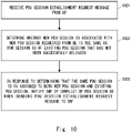
- Fig. 10 is a flowchart showing one example of the operations of the AMF 2 according to this example embodiment.
- Steps 1001 and 1002 are similar to Steps 501 and 502 in Fig. 5 .
- Step 1003 in response to determining that the same PDU Session ID is assigned to both a new PDU session and an existing PDU session, the AMF 2 informs a selected SMF 3 of a conflict of the PDU Session ID when sending the PDU Session Establishment Request message to that SMF 3.
- the AMF 2 may send the N1 SM container (PDU Session Establishment Request) to the selected SMF 3 along with an indication of a PDU Session ID conflict (e.g., "PDU Session ID Conflict” or "Duplicated PDU Session ID in AMF").
- the selected SMF 3 may be the same as or different from the SMF that manages the existing PDU session.
- the selected SMF 3 may generate a PDU Session Establishment Reject message and send it to the UE 1 to reject the establishment of the new PDU session.
- This PDU Session Establishment Reject message may indicate a new cause (e.g., 5GSM Cause) indicating that the PDU session establishment is temporarily rejected, and may indicate a back-off timer value.
- the new 5GSM Cause may be defined as, for example, "Temporarily Reject".
- the back-off timer value is applied to a new timer running in the UE 1. Alternatively, the back-off timer value may be applied to an existing timer (e.g., T3580).
- the UE 1 may start the (new or existing) timer where the back-off timer value is set and refrain from sending a new PDU Session Establishment Request until the timer expires. In other words, the UE 1 may perform transmission of a new PDU Session Establishment Request (or retransmission of the PDU Session Establishment Request that was once rejected) upon expiration of the back-off timer value sent from the selected SMF 3.
- the UE 1 may set a back-off timer value based on internally configured data of the UE 1 (UE Local configuration) in the (new or existing) timer and initiate this timer. The UE 1 may then perform transmission of a new PDU Session Establishment Request (or retransmission of the PDU Session Establishment Request that was once rejected) upon expiration of that timer.
- the back-off timer value based on the internally configured data of the UE 1 (UE Local configuration) may be, for example, a few seconds, specifically 2 to 3 seconds.
- the UE 1 may stop this timer, set a back-off timer value based on the internally configured data of the UE 1 (UE Local configuration) in this timer, and restart this timer.
- the timer for message retransmission e.g., T3580
- the UE 1 may stop this timer, set a back-off timer value based on the internally configured data of the UE 1 (UE Local configuration) in a different timer from the timer for message retransmission, and start the different timer.
- the timer for message retransmission e.g., T3580
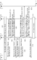
- Fig. 11 shows in detail a specific example of the PDU Session release procedure initiated by the UE 1 according to this example embodiment. Steps 1101-1107 are similar to Steps 701-707 in Fig. 7 . In the example shown in Fig. 11 , the first PDU session is managed by the SMF 3A.
- Step 1107 The NAS message of Step 1107 (PDU Session Establishment Request) is received by the AMF 2 prior to the completion of the step (Step 1111) for release (removal) of the SM context regarding the first PDU session in the 5GC.
- This NAS message may be received before the start of Step 1111, or it may be received while Step 1111 is being performed.
- Step 1111 at least includes an Nsmf_PDUSession_SMContextStatusNotify service operation (similar to Step 309 in Fig. 3 ) for notifying the AMF 2 that the SM context for the first PDU session is to be released.
- Step 1111 may further include the transmission of an N1 SM container (PDU Session Release Complete (PDU Session ID #1)) from the AMF 2 to the SMF 3A (similar to Step 307 in Fig. 3 ).
- Step 1111 may further include the transmission of an Nsmf_PDUSession_SMContextStatusNotify Ack message from the AMF 2 to the SMF 3A (similar to Step 312 in Fig. 3 ).
- Step 1108 the AMF 2 selects an SMF and sends an Nsmf_PDUSession_CreateSMContext Request message to the selected SMF (in Fig. 11 , SMF 3B that was not managing the existing PDU session).
- This message contains PDU Session ID #1 and the N1 SM container (PDU Session Establishment Request), and further contains an indication of a PDU Session ID conflict (e.g., "PDU Session ID Conflict" or "Duplicated PDU Session ID in AMF").
- the AMF 2 may send information indicating the use of the enhanced PDU Session release procedure (e.g., "5GS network feature support” information element) to the UE 1 via a Registration Accept message in a location registration process (registration procedure) of the UE 1. Then, if the AMF 2 has sent the information indicating the use of the enhanced PDU Session release procedure to the UE 1 in the location registration process, the AMF 2 may send the Nsmf_PDUSession_CreateSMContext Request message to the selected SMF (the SMF 3B in Fig. 11 ). In contrast, the AMF 2 may discard the PDU Session Establishment Request message received in Step 1107 if it has not sent the information indicating the use of the enhanced PDU Session release procedure to the UE 1 in the location registration process.
- the AMF 2 may send the Nsmf_PDUSession_CreateSMContext Request message to the selected SMF (the SMF 3B in Fig. 11 ).
- the SMF 3B responds to the UE 1 with a NAS message indicating rejection of the establishment of the new PDU session.
- the SMF 3 may generate a PDU Session Establishment Reject message and send it to the UE 1.
- the PDU Session Establishment Reject message may include a 5GSM Cause "Temporarily Reject" and a back-off timer value.
- the NAS message (e.g., PDU Session Establishment Reject message) may be sent before the start of Step 1111, or it may be sent while Step 1111 is being performed.
- the Nsmf_PDUSession_CreateSMContext Response message sent from the SMF 3 to the AMF 2 contains an N1 SM container (PDU Session Establishment Reject). This message may further contain an indication of a PDU Session ID conflict (e.g., "PDU Session ID Conflict” or "Duplicated PDU Session ID in AMF").
- PDU Session ID conflict e.g., "PDU Session ID Conflict” or "Duplicated PDU Session ID in AMF”
- the AMF 2 may select the SMF 3A that was managing the existing PDU session instead of the SMF 3B in Step 1108. In this case, the AMF 2 may send the Nsmf_PDUSession_CreateSMContext Request message to the SMF 3A and the SMF 3A may perform the processing of Step 1109.
- the operation of the AMF 2 according to this example embodiment may be performed in a procedure other than the PDU Session release procedure initiated by the UE 1 (e.g., Fig. 11 ). Specifically, the operation of the AMF 2 according to this example embodiment may be applied to PDU session release triggered by the AN 4, PDU session release initiated by the SMF 3, and PDU session release initiated by the PCF.
- the procedure described in the second example embodiment may be used to notify the AMF 2 that the UE 1 is supporting the PDU Session release procedure described in this example embodiment.
- the AMF 2 in response to determining that the same PDU Session ID is assigned to both a new PDU session and an existing PDU session, the AMF 2 notifies the SMF 3 (e.g., the SMF 3B) of duplication of the PDU Session ID. This allows the SMF 3, for example, to reject the establishment of the new PDU session. Accordingly, this example embodiment can contribute to avoiding a conflict (interference, collision, or PDU Session ID duplicated) between an uncompleted PDU session release and a new PDU session establishment that are associated with the same PDU Session ID.
- the SMF 3 e.g., the SMF 3B
- this example embodiment can contribute to avoiding a conflict (interference, collision, or PDU Session ID duplicated) between an uncompleted PDU session release and a new PDU session establishment that are associated with the same PDU Session ID.
- This example embodiment provides another solution for avoiding a conflict between establishment of a new PDU session and release of an existing PDU session.
- the configuration example of a cellular network according to this example embodiment may be similar to the example shown in Fig. 1 .
- Fig. 12 is a flowchart showing one example of the operations of the AMF 2 according to this example embodiment. Steps 1201 and 1202 are similar to Steps 501 and 502 in Fig. 5 . In Step 1203, if the new PDU Session ID is the same as that of an existing PDU session, the AMF 2 discards the PDU Session Establishment Request message without sending it to any SMF.
- the UE 1 performs a retransmission operation of the PDU Session Establishment Request message using an existing timer (i.e., T3580).
- T3580 an existing timer
- the UE 1 starts the timer T3580 in response to the transmission of the first PDU Session Establishment Request message. If the timer T3580 has expired, the UE 1 resends the PDU Session Establishment Request message to the AMF 2.
- the timer value of the timer T3580 specified in the current 3GPP specifications is 16 seconds.
- Fig. 13 shows in detail a specific example of the PDU Session release procedure initiated by the UE 1 according to this example embodiment.
- Steps 1301-1307 are similar to Steps 701-707 in Fig. 7 .
- the NAS message (PDU Session Establishment Request) of Step 1307 is received by the AMF 2 prior to the completion of the step (Step 1309) for release (removal) of the SM context regarding the first PDU session in the 5GC.
- This NAS message may be received before the start of Step 1309, or it may be received while Step 1309 is being performed.
- Step 1309 at least includes an Nsmf_PDUSession_SMContextStatusNotify service operation for notifying the AMF 2 that the SM context for the first PDU session is to be released (similar to Step 309 in Fig. 3 ).
- Step 1309 may further include the transmission of an N1 SM container (PDU Session Release Complete (PDU Session ID #1)) from the AMF 2 to the SMF 3 (similar to Step 307 in Fig. 3 ).
- Step 1309 may further include the transmission of an Nsmf_PDUSession_SMContextStatusNotify Ack message from the AMF 2 to the SMF 3 (similar to Step 312 in Fig. 3 ).
- the operation of the AMF 2 according to this example embodiment may be performed in a procedure other than the PDU Session release procedure initiated by the UE 1 (e.g., Fig. 13 ). Specifically, the operation of the AMF 2 according to this example embodiment can be applied to PDU session release triggered by the AN 4, PDU session release initiated by the SMF 3, and PDU session release initiated by the PCF.
- the procedure described in the second example embodiment may be used to notify the AMF 2 that the UE 1 is supporting the PDU Session release procedure described in this example embodiment.
- this example embodiment in response to determining that the same PDU Session ID is assigned to both a new PDU session and an existing PDU session, the AMF 2 discards the PDU Session Establishment Request message. Accordingly, this example embodiment can contribute to avoiding a conflict (interference, collision, or PDU Session ID duplicated) between an uncompleted PDU session release and a new PDU session establishment that are associated with the same PDU Session ID.
- This example embodiment provides another solution for avoiding a conflict between establishment of a new PDU session and release of an existing PDU session.
- the configuration example of a cellular network according to this example embodiment may be similar to the example shown in Fig. 1 .
- Fig. 14 is a flowchart showing one example of the operations of the UE 1 according to this example embodiment.
- Step 1401 for a predetermined period associated with release of a first PDU session, the UE 1 assigns to a new PDU session to be established a different PDU Session ID from the first PDU Session ID that was assigned to the first PDU session.
- Step 1402 the UE 1 initiates a PDU session establishment procedure using the PDU Session ID determined in Step 1401.
- the above-described predetermined period may be specified in the 3GPP specifications. Additionally or alternatively, the UE 1 may configure the predetermined period based on internally configured data of the UE 1 (UE Local configuration). Additionally or alternatively, the AMF 2 or the SMF 3 may set the predetermined period in the UE 1.
- the predetermined period may be, for example, a few seconds, Specifically 2 to 3 seconds.
- the UE 1 may stop this timer, set a timer value based on the internally configured data of the UE 1 (UE Local configuration) in this timer, and restart this timer.
- the UE 1 may stop this timer, set a timer value based on internally configured data of the UE 1 (UE Local configuration) in a different timer from the timer for message retransmission, and start the different timer.
- the UE 1 may operate to not assign the first PDU Session ID to a new PDU session to be established, for the predetermined period, in response to receiving a PDU Session Release Command message sent from the SMF 3 to the UE 1 to indicate release of the first PDU session.
- the UE 1 may operate to not assign the first PDU Session ID to a new PDU session to be established, for the predetermined period, in response to releasing the first PDU session in the UE 1 based on the reception of a PDU Session Release Command message from the SMF 3.
- the UE 1 may operate to not assign the first PDU Session ID to a new PDU session to be established, for the predetermined period, in response to sending of a PDU Session Release Complete message to acknowledge (or accept) a PDU Session Release Command message from the SMF 3.
- the UE 1 may operate to start a timer in response to release of the first PDU session and not assign the first PDU Session ID to a new PDU session to be established until the timer expires.
- the UE 1 does not assign the PDU Session ID of a PDU session to be released to a new PDU session for a predetermined period. Accordingly, this example embodiment can contribute to avoiding a conflict (interference, collision, or PDU Session ID duplicated) between an uncompleted PDU session release and a new PDU session establishment that are associated with the same PDU Session ID.
- This example embodiment provides another solution for avoiding a conflict between establishment of a new PDU session and release of an existing PDU session.
- the configuration example of a cellular network according to this example embodiment may be similar to the example shown in Fig. 1 .
- Fig. 15 is a flowchart showing one example of the operations of the UE 1 according to this example embodiment.
- the UE 1 assigns to a new PDU session to be established a PDU Session ID different from one or more PDU Session IDs that were most recently used.
- the UE 1 initiates a PDU session establishment procedure using the PDU Session ID determined in Step 1501.
- the UE 1 may change the value of the PDU Session ID every time a new PDU session is established. More specifically, the UE 1 may have a plurality of candidate values for PDU Session IDs and increment the value of the PDU Session ID assigned to a new PDU session in sequence. If the number of candidate values for PDU Session IDs is sufficiently large, the UE 1 can assign a newly established PDU session a PDU Session ID different from one or more PDU Session IDs that were just used.
- this example embodiment it is possible to prevent the PDU Session ID of a PDU session to be released from being used immediately for a new PDU session. Accordingly, this example embodiment can contribute to avoiding a conflict (interference, collision, or PDU Session ID duplicated) between an uncompleted PDU session release and a new PDU session establishment that are associated with the same PDU Session ID.
- This example embodiment provides another solution for avoiding a conflict between establishment of a new PDU session and release of an existing PDU session.
- the configuration example of a cellular network according to this example embodiment may be similar to the example shown in Fig. 1 .
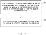
- Fig. 16 is a flowchart showing one example of the operations of the UE 1 according to this example embodiment.
- Step 1601 in at least a first attempt to establish a new PDU session performed after release of a first PDU session, the UE 1 assigns to the new PDU session a PDU Session ID different from the first PDU Session ID that was assigned to the first PDU session.
- Step 1602 the UE 1 initiates a PDU session establishment procedure using the PDU Session ID determined in Step 1601.
- the UE 1 assigns to the new PDU session a PDU Session ID different from the first PDU Session ID that was assigned to the first PDU session.
- the UE 1 assigns to the new PDU session a PDU Session ID different from the first PDU Session ID that was assigned to the first PDU session.
- the UE 1 assigns to the new PDU session a PDU Session ID different from the first PDU Session ID that was assigned to the first PDU session.
- this example embodiment it is possible to prevent the PDU Session ID of a PDU session to be released from being used immediately for a new PDU session. Accordingly, this example embodiment can contribute to avoiding a conflict (interference, collision, or PDU Session ID duplicated) between an uncompleted PDU session release and a new PDU session establishment that are associated with the same PDU Session ID.
- Fig. 17 is a block diagram showing a configuration example of the UE 1.
- a Radio Frequency (RF) transceiver 1701 performs analog RF signal processing to communicate with NG-RAN nodes.
- the RF transceiver 1701 may include a plurality of transceivers.
- the analog RF signal processing performed by the RF transceiver 1701 includes frequency up-conversion, frequency down-conversion, and amplification.
- the RF transceiver 1701 is coupled to an antenna array 1702 and a baseband processor 1703.
- the RF transceiver 1701 receives modulated symbol data (or OFDM symbol data) from the baseband processor 1703, generates a transmission RF signal, and supplies the transmission RF signal to the antenna array 1702. Further, the RF transceiver 1701 generates a baseband reception signal based on a reception RF signal received by the antenna array 1702, and supplies the baseband reception signal to the baseband processor 1703.
- the RF transceiver 1701 may include an analog beamformer circuit for beam forming.
- the analog beamformer circuit includes, for example, a plurality of phase shifters and a plurality of power amplifiers.
- the baseband processor 1703 performs digital baseband signal processing (i.e., data-plane processing) and control-plane processing for radio communication.
- the digital baseband signal processing includes (a) data compression/decompression, (b) data segmentation/concatenation, (c) composition/decomposition of a transmission format (i.e., transmission frame), (d) channel coding/decoding, (e) modulation (i.e., symbol mapping)/demodulation, and (f) generation of OFDM symbol data (i.e., baseband OFDM signal) by Inverse Fast Fourier Transform (IFFT).
- IFFT Inverse Fast Fourier Transform
- control-plane processing includes communication management of layer 1 (e.g., transmission power control), layer 2 (e.g., radio resource management and hybrid automatic repeat request (HARQ) processing), and layer 3 (e.g., signaling regarding attach, mobility, and call management).
- layer 1 e.g., transmission power control
- layer 2 e.g., radio resource management and hybrid automatic repeat request (HARQ) processing
- layer 3 e.g., signaling regarding attach, mobility, and call management.
- the digital baseband signal processing by the baseband processor 1703 may include, for example, signal processing of a Service Data Adaptation Protocol (SDAP) layer, a Packet Data Convergence Protocol (PDCP) layer, a Radio Link Control (RLC) layer, a Medium Access Control (MAC) layer, and a Physical (PHY) layer. Further, the control-plane processing performed by the baseband processor 1703 may include processing of a Non-Access Stratum (NAS) protocol, a Radio Resource Control (RRC) protocol, and MAC Control Elements (CEs).
- SDAP Service Data Adaptation Protocol
- PDCP Packet Data Convergence Protocol
- RLC Radio Link Control
- MAC Medium Access Control
- PHY Physical
- the control-plane processing performed by the baseband processor 1703 may include processing of a Non-Access Stratum (NAS) protocol, a Radio Resource Control (RRC) protocol, and MAC Control Elements (CEs).
- NAS Non-Access Stratum
- RRC Radio Resource Control
- the baseband processor 1703 may perform Multiple Input Multiple Output (MIMO) encoding and pre-coding for beam forming.
- MIMO Multiple Input Multiple Output
- the baseband processor 1703 may include a modem processor (e.g., a Digital Signal Processor (DSP) that performs the digital baseband signal processing and a protocol stack processor (e.g., a Central Processing Unit (CPU) or a Micro Processing Unit (MPU)) that performs the control-plane processing.
- DSP Digital Signal Processor
- protocol stack processor e.g., a Central Processing Unit (CPU) or a Micro Processing Unit (MPU)
- the protocol stack processor which performs the control-plane processing, may be integrated with an application processor 1704 described in the following.
- the application processor 1704 is also referred to as a CPU, an MPU, a microprocessor, or a processor core.
- the application processor 1704 may include a plurality of processors (processor cores).
- the application processor 1704 loads a system software program (Operating System (OS)) and various application programs (e.g., a call application, a WEB browser, a mailer, a camera operation application, and a music player application) from a memory 1706 or from another memory (not shown) and executes these programs, thereby providing various functions of the UE 1.
- OS Operating System
- various application programs e.g., a call application, a WEB browser, a mailer, a camera operation application, and a music player application
- the baseband processor 1703 and the application processor 1704 may be integrated on a single chip.
- the baseband processor 1703 and the application processor 1704 may be implemented in a single System on Chip (SoC) device 1705.
- SoC System on Chip
- An SoC device may be referred to as a system Large Scale integration (LSI) or a chipset.
- the memory 1706 is a volatile memory, a non-volatile memory, or a combination thereof.
- the memory 1706 may include a plurality of memory devices that are physically independent from each other.
- the volatile memory is, for example, a Static Random Access Memory (SRAM), a Dynamic RAM (DRAM), or any combination thereof.
- the non-volatile memory is a mask Read Only Memory (MROM), an Electrically Erasable Programmable ROM (EEPROM), a flash memory, a hard disc drive, or any combination thereof.
- the memory 1706 may include, for example, an external memory device that can be accessed from the baseband processor 1703, the application processor 1704, and the SoC 1705.
- the memory 1706 may include an internal memory device that is integrated in the baseband processor 1703, the application processor 1704, or the SoC 1705. Further, the memory 1706 may include a memory in a Universal Integrated Circuit Card (UICC).
- UICC Universal Integrated Circuit Card
- the memory 1706 may store one or more software modules (computer programs) 1707 including instructions and data to perform the processing by the UE 1 described in the above example embodiments.
- the baseband processor 1703 or the application processor 1704 may be configured to load these software modules 1707 from the memory 1706 and execute the loaded software modules, thereby performing the processing of the UE 1 described in the above example embodiments with reference to the drawings.
- control plane processes and operations described in the above example embodiments and performed by the UE 1 can be achieved by the elements other than the RF transceiver 1701 and the antenna array 1702, i.e., achieved by the memory 1706 storing the software modules 1707 and at least one of the baseband processor 1703 and the application processor 1704.
- Fig. 18 shows a configuration example of the AMF 2.
- the SMF 3 may also be configured as shown in Fig. 18 .
- the AMF 2 includes a network interface 1801, a processor 1802, and a memory 1803.
- the network interface 1801 is used, for example, to communicate with RAN nodes, and to communicate with other network functions (NFs) or nodes in the 5GC.
- the other NFs or nodes in the 5GC include, for example, a UDM, an SMF, and a PCF.
- the network interface 1801 may include, for example, a network interface card (NIC) conforming to the IEEE 802.3 series.
- NIC network interface card
- the processor 1802 may include, for example, a microprocessor, a Micro Processing Unit (MPU), or a Central Processing Unit (CPU).
- the processor 1802 may include a plurality of processors.
- the memory 1803 is composed of a combination of a volatile memory and a non-volatile memory.
- the memory 1803 may include a plurality of memory devices that are physically independent from each other.
- the volatile memory is, for example, a Static Random Access Memory (SRAM), a Dynamic RAM (DRAM), or any combination thereof.
- the non-volatile memory is, for example, a mask Read Only Memory (MROM), an Electrically Erasable Programmable ROM (EEPROM), a flash memory, a hard disc drive, or any combination thereof.
- the memory 1803 may include a storage located apart from the processor 1802. In this case, the processor 1802 may access the memory 1803 via the network interface 1801 or an I/O interface (not shown).
- the memory 1803 may store one or more software modules (computer programs) 1804 including instructions and data to perform processing by the AMF 2 described in the above example embodiments.
- the processor 1802 may be configured to load the software modules 1804 from the memory 1803 and execute the loaded software modules, thereby performing the processing of the AMF 2 described in the above example embodiments.
- An Access and Mobility Management Function (AMF) node comprising:
- the AMF node according to Supplementary Note A1, wherein the at least one processor is configured to send the second NAS message to the radio terminal in response to receiving from the SMF a second control message notifying the AMF node that a Session Management (SM) context for the first PDU session is to be released.
- SM Session Management
- the AMF node according to Supplementary Note A2, wherein the at least one processor is configured to release a PDU session level context that is related to the first PDU session and is managed by the AMF node in response to reception of the second control message.
- the AMF node according to Supplementary Note A2, wherein the PDU session level context includes an association between the first PDU Session ID and SMF information indicating the SMF.
- the AMF node according to Supplementary Note A6, wherein the third SM container contains a message sent from the SMF to the radio terminal to notify the radio terminal that a Session Management (SM) context for the first PDU session is to be released.
- SM Session Management
- the AMF node according to any one of Supplementary Notes A1 to A7, wherein the second NAS message notifies the radio terminal that the SM context for the first PDU session has been successfully released in a core network.
- the AMF node according to any one of Supplementary Notes A1 to A8, wherein the second NAS message allows the radio terminal to assign the first PDU Session ID to a new PDU session different from the first PDU session.
- the AMF node according to any one of Supplementary Notes A1 to A9, wherein the at least one processor is configured to receive, from the radio terminal, capability information indicating that the radio terminal has a capability of handling a PDU Session release procedure involving sending and receiving of the second NAS message.
- the AMF node according to Supplementary Note A10, wherein the at least one processor is configured to receive the capability information from the radio terminal in a registration procedure of the radio terminal.
- the AMF node according to Supplementary Note A10 or A11, wherein the at least one processor is configured to determine whether to use the PDU Session release procedure, involving sending and receiving of the second NAS message, for the radio terminal depending on whether the at least one processor has received the capability information.
- a radio terminal comprising:
- the at least one processor is configured to recognize in response to the reception of the second NAS message that the first PDU Session ID can be assigned to a new PDU session different from the first PDU session.
- the radio terminal according to any one of Supplementary Notes A13 to A16, wherein the second NAS message allows the radio terminal to assign the first PDU Session ID to a new PDU session different from the first PDU session.
- the radio terminal according to any one of Supplementary Notes A13 to A17, wherein the at least one processor is configured to not assign the first PDU Session ID to a new PDU session to be established at least until the at least one processor receives the second NAS message.
- the radio terminal according to any one of Supplementary Notes A13 to A18, wherein the at least one processor is configured to send, to the AMF, capability information indicating that the radio terminal has a capability of handling a PDU Session release procedure involving sending and receiving of the second NAS message.
- the radio terminal according to Supplementary Note A19 wherein the at least one processor is configured to send the capability information to the AMF in a registration procedure of the radio terminal.
- a method for an Access and Mobility Management Function (AMF) node comprising:
- a method for a radio terminal comprising:
- a program for causing a computer to perform a method for a radio terminal comprising:
- An Access and Mobility Management Function (AMF) node comprising:
- the AMF node according to Supplementary Note B1, wherein the at least one processor is configured to, in the procedure, suspend establishment of the new PDU session until release of the first PDU session is completed.
- the AMF node according to Supplementary Note B2, wherein the at least one processor is configured to refrain from sending a Non-Access Stratum (NAS) message for establishment of the new PDU session to a Session Management Function (SMF) in order to suspend establishment of the new PDU session.
- NAS Non-Access Stratum
- SMF Session Management Function
- the AMF node according to Supplementary Note B1, wherein the at least one processor is configured to, in the procedure, send a NAS message indicating rejection of establishment of the new PDU session to the radio terminal, without sending a Non-Access Stratum (NAS) message for establishment of the new PDU session to a Session Management Function (SMF).
- NAS Non-Access Stratum
- the AMF node according to Supplementary Note B5, wherein the PDU Session Establishment Reject message indicates a cause indicating that PDU session establishment is temporarily rejected, and indicates a back-off timer value.
- the AMF node according to Supplementary Note B1, wherein the at least one processor is configured to, in the procedure, send an indication of a PDU Session ID conflict to a Session Management Function (SMF) when sending a Non-Access Stratum (NAS) message for establishment of the new PDU session to the SMF.
- SMF Session Management Function
- NAS Non-Access Stratum
- the AMF node according to Supplementary Note B7, wherein the at least one processor is configured to send the NAS message to the SMF with the indication of the PDU Session ID conflict.
- the AMF node according to Supplementary Note B1, wherein the at least one processor is configured to, in the procedure, discard a Non-Access Stratum (NAS) message for establishment of the new PDU session at the AMF node without sending the NAS message to a Session Management Function (SMF).
- NAS Non-Access Stratum
- SMF Session Management Function
- a method for an Access and Mobility Management Function (AMF) node comprising:
- a Session Management Function (SMF) node comprising:
- the SMF node according to Supplementary Note B13, wherein the at least one processor is configured to send the second NAS message to the radio terminal via the AMF in response to receiving an indication of a PDU Session ID conflict from the AMF along with the first NAS message.
- the SMF node according to Supplementary Note B13 or B14, wherein the second NAS message indicates a cause indicating that PDU session establishment is temporarily rejected, and indicates a back-off timer value.
- a method for a Session Management Function (SMF) node comprising:
- a radio terminal comprising:
- the at least one processor is configured to, in response to receiving a PDU session Release Command message sent from a Session Management Function (SMF) to the radio terminal in order to indicate the release of the first PDU session, not assign the first PDU Session ID to a new PDU session to be established, during the first period.
- SMF Session Management Function
- the at least one processor is configured to, in response to releasing the first PDU session based on reception of a PDU Session Release Command message from a Session Management Function (SMF), not assign the first PDU Session ID to a new PDU session to be established, during the first period.
- SMF Session Management Function
- the at least one processor is configured to, in response to sending a PDU Session Release Complete message to acknowledge a PDU Session Release Command message from a Session Management Function (SMF), not assign the first PDU Session ID to a new PDU session to be established, during the first period.
- SMF Session Management Function
- the at least one processor is configured to start a timer in response to release of the first PDU session and not assign the first PDU Session ID to a new PDU session to be established until the timer expires.
- radio terminal according to Supplementary Note C1, wherein the at least one processor is configured to be set with a value of the first period.
- a method for a radio terminal comprising:
- a radio terminal comprising:
- a method for a radio terminal comprising:
- a radio terminal comprising:
- a method for a radio terminal comprising:
Landscapes
- Engineering & Computer Science (AREA)
- Computer Networks & Wireless Communication (AREA)
- Signal Processing (AREA)
- Mobile Radio Communication Systems (AREA)
Abstract
Description
- The present disclosure relates to a cellular network and, in particular, to release and establishment of a connectivity service between UE and an external data network.
- The 5G system (5GS) connects user equipment (UE) to an external data network (Data Network (DN)). In the 5G architecture, connectivity services between the UE and the DN are supported by Protocol Data Unit (PDU) sessions. A PDU session is an association between the UE and the DN and is used to provide a PDU connectivity service (i.e., exchange of PDUs between the UE and the DN). A PDU session is established between the UE and a User Plane Function (UPF) (i.e., PDU session anchor) to which the DN is connected. In terms of data transfer, a PDU session consists of a tunnel (N9 tunnel) in the 5G core network (5GC), a tunnel (N3 tunnel) between the 5GC and an Access Network (AN), and one or more radio bearers.
- PDU sessions are managed by a Session Management Function (SMF). The SMF sends and receives SM signalling messages (NAS-SM messages, N1 SM messages) to and from the Non-Access Stratum (NAS)-SM layer of a UE via a network function (NF) service (i.e., communication service with a UE) provided by an Access and Mobility Management Function (AMF).
- The AMF terminates a single signalling connection (i.e., N1 NAS signalling connection) with a UE. The Single N1 NAS signalling connection is used for both Registration and Connection Managements (RM/CM) for the UE, and SM-related messages and procedures.
- A PDU session is established in response to a request from a UE or a network. A PDU Session ID is used to specify a PDU session. A PDU Session ID is an identifier that is generated by a UE and is unique among PDU Sessions that this UE deals with. A PDU Session ID assigned to a PDU session to be newly generated shall not be the same as any of the IDs of existing PDU sessions. The term "PDU Session ID" used herein may indicate the value of a PDU Session ID generated for a PDU session.
- Non-Patent Literature 1 (3GPP TS 23.502) and Non-Patent Literature 2 (3GPP TS 24.501) specify a PDU session establishment procedure and a PDU Session release procedure. More specifically, the PDU session establishment procedure is described, for example, in clause 4.3.2.2 of
Non-Patent Literature 1 and clause 6.4.1 of Non-PatentLiterature 2. The PDU Session release procedure is described, for example, in clause 4.3.4.2 ofNon-Patent Literature 1 and clauses 6.3.3 and 6.4.3 of Non-PatentLiterature 2. -
- [Non-Patent Literature 1] 3GPP TS 23.502 V16.2.0 (2019-09) "3rd Generation Partnership Project; Technical Specification Group Services and System Aspects; Procedures for the 5G System (5GS); Stage 2 (Release 16)", September 2019
- [Non-Patent Literature 2] 3GPP TS 24.501 V16.2.0 (2019-09) "3rd Generation Partnership Project; Technical Specification Group Core Network and Terminals; Non-Access-Stratum (NAS) protocol for 5G System (5GS); Stage 3 (Release 16)", September 2019
- According to the UE-initiated PDU Session release procedure disclosed in clause 4.3.4.2 of
Non-Patent Literature 1, the UE receives a NAS message containing a PDU Session Release Command from the AMF. The PDU Session Release Command is SM signalling (N1 SM message) sent from the SMF to the UE via the AMF in order to instruct the UE to release the PDU session. Then, the UE sends a NAS message containing PDU Session Release Complete to the AMF in order to acknowledge the PDU Session Release Command. This NAS message contains the PDU Session ID of the PDU session to be released, and an N1 SM container (PDU Session Release Complete). The N1 SM container (PDU Session Release Complete) is transmitted to the SMF via the AMF. The PDU Session Release Complete may instead be called PDU Session Release Ack. - After the above, the SMF performs (or invokes) an Nsmf_PDUSession_SMContextStatusNotify service operation to notify the AMF that the SM context for the PDU session is to be released. The Nsmf_PDUSession_SMContextStatusNotify is one of the NF services provided by the SMF. An Nsmf_PDUSession_SMContextStatusNotify is used by the SMF to notify its consumer (e.g., AMF) of the status of the SM context regarding a PDU session.
- The AMF releases a UE context (i.e., PDU session level context) related to the PDU session in response to the Nsmf_PDUSession_SMContextStatusNotify message. The PDU session level context managed by the AMF includes associations among the SMF information (e.g., SMF ID), PDU Session ID, and Data Network Name (DNN).
- In addition, the SMF performs (or invokes) an Nudm_UECM_Deregistration service operation, including the Data Network Name (DNN) and PDU Session ID, to release the context regarding the PDU session to be released. The Nudm_UECM_Deregistration is one of the NF services provided by a Unified Data Management (UDM). An NF consumer (e.g., SMF) uses the Nudm_UECM_Deregistration service operation to request the UDM to delete information related to the NF. In response to the request from the SMF, the UDM removes the association between the SMF identity and the associated DNN and PDU Session ID.
- That is, according to the UE-initiated PDU Session release procedure disclosed in clause 4.3.4.2 of Non-Patent
Literature 1, after the UE sends PDU Session Release Complete (SM signalling) to the SMF via the AMF, the SMF releases the context (resources) in the 5GC regarding this PDU session (or removes this context from the 5GC) while cooperating with the AMF and the UDM. - However, in the existing procedures, the UE may be able to request the 5GC to establish a new PDU session just after sending PDU Session Release Complete (SM signalling). In addition, the UE may be able to use the PDU Session ID associated with a PDU session that has just been released for a new PDU session to be established. This is because, in the UE's point view, it can be considered that PDU Session ID is considered to be no longer associated with any of the existing PDU sessions.
- Accordingly, before the PDU session release in the 5GC (i.e., removal of the context regarding the PDU session) is successfully completed, the 5GC may receive a PDU session establishment request from the UE indicating the same PDU Session ID as that of the PDU session to be released. In this case, the 5GC may not be able to correctly distinguish the new PDU session to be established from the PDU session to be released. This is because, PDU Session IDs generated (or determined) by the UE are used in both the management of PDU sessions by the SMF and the management of the UE context (PDU Session level context) related to PDU sessions by the AMF.
- For example, an unfavorable scenario including the following steps (1)-(3) may occur. In step (1), a UE-initiated PDU Session release procedure is performed to release an existing PDU session that is managed by
SMF # 1 and is associated with PDUSession ID # 1. In this release procedure, the UE sends a NAS message containing PDUSession ID # 1 and an N1 SM container (PDU Session Release Complete) to the AMF. - In step (2), immediately after the transmission of the PDU Session Release Complete, the UE selects PDU
Session ID # 1 to establish a new PDU session and sends a NAS message for requesting establishment of a new PDU session to the AMF. This NAS message contains PDUSession ID # 1, a Request type indicating "initial request" or "initial emergency request", and an N1 SM container (PDU Session Establishment Request). The AMF selects, for example,SMF # 2 for a new PDU session and sends an Nsmf_PDUSession_CreateSMContext Request to theSMF # 2. This Nsmf_PDUSession_CreateSMContext Request contains PDUSession ID # 1 and the N1 SM container (PDU Session Establishment Request). The Nsmf_PDUSession_CreateSMContext service operation is one of the NF services provided by an SMF. The AMF as an NF consumer uses the Nsmf_PDUSession_CreateSMContext to create an AMF-SMF association to support a PDU session. - In step (3), while the procedure for establishing a new PDU session related to Step (2) is taking place,
SMF # 1 sends an Nsmf_PDUSession_SMContextStatusNotify message to the AMF indicating that the SM context for the existing PDU session is to be released. In this case, because the PDU Session ID of the new PDU session is the same as that of the PDU session to be released, for example, the AMF may accidentally remove the UE context (PDU Session level context) created for the new PDU session. - As described above, in the existing PDU session establishment and PDU Session release procedures, a problem may occur in the case where the UE initiates the PDU session establishment procedure before the PDU session release is successfully completed within the 5GC. Specifically, there is a risk of conflict or collision between an uncompleted PDU session release and a new PDU session establishment that are associated with the same PDU Session ID. Such a conflict (or a situation where such a conflict is occurring) can be referred to as "PDU Session ID duplicated".
- This problem may occur not only in the case where the UE requests the SMF for a PDU session release (i.e., in the UE-initiated PDU Session release procedure). Specifically, this problem may occur also in the case where a Policy Control Function (PCF) requests the SMF for a PDU session release. This problem can also occur in the case where an Access Network (AN) requests the SMF for a PDU session release, in other words, the AN notifies the SMF of a release of the resources related to a PDU session and the SMF decides to release the PDU session based on the notification. Furthermore, this problem may occur in the case where the SMF decides to release a PDU session and initiates the PDU session release.
- One of the objects to be attained by example embodiments disclosed herein is to provide apparatuses, methods, and programs that contribute to avoiding a conflict (or collision) between an uncompleted PDU session release and a new PDU session establishment that are associated with the same PDU Session ID. It should be noted that this object is merely one of the objects to be attained by the example embodiments disclosed herein. Other objects or problems and novel features will be made apparent from the following description and the accompanying drawings.
- In a first aspect, an AMF node includes at least one memory and at least one processor coupled to the at least one memory. The at least one processor is configured to, in response to receiving a first control message containing a first Session Management (SM) container from a Session Management Function (SMF), send a first Non-Access Stratum (NAS) message containing the first SM container to a radio terminal. The first SM container contains a PDU Session Release Command message sent from the SMF to the radio terminal in order to indicate release of a first PDU session associated with a first Protocol Data Unit (PDU) Session ID. The at least one processor is further configured to, after sending the first NAS message to the radio terminal, send to the radio terminal a second NAS message to indicate that the first PDU Session ID can be assigned to another PDU session different from the first PDU session.
- In a second aspect, a method for an AMF node includes the following steps (a) and (b):
- (a) in response to receiving a first control message containing a first Session Management (SM) container from a Session Management Function (SMF), sending a first Non-Access Stratum (NAS) message containing the first SM container to a radio terminal, the first SM container containing a PDU Session Release Command message sent from the SMF to the radio terminal in order to indicate release of a first PDU session associated with a first Protocol Data Unit (PDU) Session ID; and
- (b) after sending the first NAS message to the radio terminal, sending to the radio terminal a second NAS message to indicate that the first PDU Session ID can be assigned to another PDU session different from the first PDU session.
- In a third aspect, a radio terminal includes at least one memory and at least one processor coupled to the at least one memory. The at least one processor is configured to receive from an Access and Mobility Management Function (AMF) a first Non-Access Stratum (NAS) message containing a first Session Management (SM) container. The first SM container contains a PDU Session Release Command message sent from a Session Management Function (SMF) to the radio terminal in order to indicate release of a first PDU session associated with a first Protocol Data Unit (PDU) Session ID. The at least one processor is further configured to, after receiving the first NAS message, receive from the AMF a second NAS message indicating that the first PDU Session ID can be assigned to another PDU session different from the first PDU session.
- In a fourth aspect, a method for a radio terminal includes the following steps (a) and (b):
- (a) receiving from an Access and Mobility Management Function (AMF) a first Non-Access Stratum (NAS) message containing a first Session Management (SM) container, the first SM container containing a PDU Session Release Command message sent from a Session Management Function (SMF) to the radio terminal in order to indicate release of a first PDU session associated with a first Protocol Data Unit (PDU) Session ID; and
- (b) after receiving the first NAS message, receiving from the AMF a second NAS message indicating that the first PDU Session ID can be assigned to another PDU session different from the first PDU session.
- In a fifth aspect, a radio terminal includes at least one memory and at least one processor coupled to the at least one memory. The at least one processor is configured to receive from an Access and Mobility Management Function (AMF) a first Non-Access Stratum (NAS) message containing a first Session Management (SM) container . The first SM container contains a PDU Session Release Command message sent from a Session Management Function (SMF) to the radio terminal in order to indicate release of a first PDU session associated with a first Protocol Data Unit (PDU) Session ID. The at least one processor further receives a second NAS message from the AMF after receiving the first NAS message, and the at least one processor is allowed to assign the first PDU Session ID by receiving the second NAS message.
- In a sixth aspect, a method of a radio terminal includes the following steps (a) and (b):
- (a) receiving from an Access and Mobility Management Function (AMF) a first Non-Access Stratum (NAS) message containing a first Session Management (SM) container, the first SM container containing a PDU Session Release Command message sent from a Session Management Function (SMF) to the radio terminal in order to indicate release of a first PDU session associated with a first Protocol Data Unit (PDU) Session ID; and
- (b) receiving a second NAS message from the AMF after receiving the first NAS message, and being allowed to assign the first PDU Session ID by receiving the second NAS message.
- In a seventh aspect, a radio terminal includes at least one memory and at least one processor coupled to the at least one memory. The at least one processor is configured to, upon receiving from an Access and Mobility Management Function (AMF) a first control message that contains a Session Management (SM) container including a PDU Session Release Command, be unable or not allowed to assign a PDU Session ID specified by the PDU Session Release Command to another PDU session other than a PDU session specified by the PDU Session Release Command. The at least one processor is configured to, by receiving from an Access and Mobility Management Function (AMF) a first control message that contains a Session Management (SM) container including a NAS Notify, be allowed to assign a PDU Session ID specified by the NAS Notify to the other PDU session.
- In an eighth aspect, a method for a radio terminal includes the following steps (a) and (b):
- (a) upon receiving from an Access and Mobility Management Function (AMF) a first control message that contains a Session Management (SM) container including a PDU Session Release Command, being unable or not allowed to assign a PDU Session ID specified by the PDU Session Release Command to another PDU session other than a PDU session specified by the PDU Session Release Command; and
- (b) by receiving from an Access and Mobility Management Function (AMF) a first control message that contains a Session Management (SM) container including a NAS Notify, being allowed to assign a PDU Session ID specified by the NAS Notify to the other PDU session.
- In a ninth aspect, an AMF node includes at least one memory and at least one processor coupled to the at least one memory. The at least one processor is configured to determine whether a new PDU Session ID associated with a new Protocol Data Unit (PDU) session requested from a radio terminal is the same as a first PDU Session ID associated with an existing first PDU session that has not been successfully released. The at least one processor is further configured to, if the new PDU Session ID is the same as the first PDU Session ID, perform a procedure for avoiding a conflict between establishment of the new PDU session and release of the first PDU session.
- In a tenth aspect, a method for an AMF node includes the following steps (a) and (b):
- (a) determining whether a new PDU Session ID associated with a new Protocol Data Unit (PDU) session requested from a radio terminal is the same as a first PDU Session ID associated with an existing first PDU session that has not been successfully released; and
- (b) if the new PDU Session ID is the same as the first PDU Session ID, performing a procedure for avoiding a conflict between establishment of the new PDU session and release of the first PDU session .
- In an eleventh aspect, an SMF node includes at least one memory and at least one processor coupled to the at least one memory. The at least one processor is configured to receive a first NAS message for establishment of a new Protocol Data Unit (PDU) session from a radio terminal via an Access and Mobility Management Function (AMF). The at least one processor is further configured to, if a new PDU Session ID associated with the new PDU session is the same as a first PDU Session ID associated with an existing first PDU session that has not been successfully released, send a second NAS message indicating rejection of establishment of the new PDU session to the radio terminal via the AMF.
- In a twelfth aspect, a method for an SMF node includes the following steps (a) and (b):
- (a) receiving a first NAS message for establishment of a new Protocol Data Unit (PDU) session from a radio terminal via an Access and Mobility Management Function (AMF); and
- (b) if a new PDU Session ID associated with the new PDU session is the same as a first PDU Session ID associated with an existing first PDU session that has not been successfully released, sending a second NAS message indicating rejection of establishment of the new PDU session to the radio terminal via the AMF.
- In a thirteenth aspect, a radio terminal includes at least one memory and at least one processor coupled to the at least one memory. The at least one processor is configured to, for a first period associated with release of a first Protocol Data Unit (PDU) session, assign to a new PDU session to be established a PDU Session ID different from a first PDU Session ID that was assigned to the first PDU session.
- In a fourteenth aspect, a method for a radio terminal includes the following steps (a) and (b):
- (a) for a first period associated with release of a first Protocol Data Unit (PDU) session, assigning to a new PDU session to be established a PDU Session ID different from a first PDU Session ID that was assigned to the first PDU session; and
- (b) initiating a PDU session establishment procedure using the different PDU Session ID.
- In a fifteenth aspect, a radio terminal includes at least one memory and at least one processor coupled to the at least one memory. The at least one processor is configured to assign a Protocol Data Unit (PDU) Session ID that is different from most recently used one or more PDU Session IDs to a new PDU session to be established.
- In a sixteenth aspect, a method for a radio terminal includes the following steps (a) and (b):
- (a) assigning a Protocol Data Unit (PDU) Session ID that is different from most recently used one or more PDU Session IDs to a new PDU session to be established; and
- (b) initiating a PDU session establishment procedure using the different PDU Session ID.
- In a seventeenth aspect, a radio terminal includes at least one memory and at least one processor coupled to the at least one memory. The at least one processor is configured to, in at least a first attempt to establish a new Protocol Data Unit (PDU) session performed after release of a first PDU session, assign to the new PDU session a PDU Session ID different from a first PDU Session ID that was assigned to the first PDU session.
- In an eighteenth aspect, a method for a radio terminal includes the following steps (a) and (b):
- (a) in at least a first attempt to establish a new Protocol Data Unit (PDU) session performed after release of a first PDU session, assigning to the new PDU session a PDU Session ID different from a first PDU Session ID that was assigned to the first PDU session; and
- (b) initiating a PDU session establishment procedure using the different PDU Session ID.
- In a nineteenth aspect, a program includes instructions (software codes) that, when loaded into a computer, cause the computer to perform the method according to the above-described second, fourth, sixth, eighth, tenth, twelfth, fourteenth, sixteenth, or eighteenth aspect.
- According to the above-described aspects, it is possible to provide apparatuses, methods, and programs that contribute to avoiding a conflict (or collision) between an uncompleted PDU session release and a new PDU session establishment that are associated with the same PDU Session ID.
-
-
Fig. 1 is a diagram showing a configuration example of a cellular network according to an example embodiment; -
Fig. 2 is a sequence diagram showing one example of operations of a UE, an AMF, and an SMF according to an example embodiment; -
Fig. 3 is a sequence diagram showing one example of operations of a UE, an AMF, and an SMF according to an example embodiment; -
Fig. 4 is a sequence diagram showing one example of operations of a UE and an AMF according to an example embodiment; -
Fig. 5 is a flowchart showing one example of operations of an AMF according to an example embodiment; -
Fig. 6 is a flowchart showing one example of operations of an AMF according to an example embodiment; -
Fig. 7 is a sequence diagram showing one example of operations of a UE, an AMF, and an SMF according to an example embodiment; -
Fig. 8 is a flowchart showing one example of operations of an AMF according to an example embodiment; -
Fig. 9 is a sequence diagram showing one example of operations of a UE, an AMF, and an SMF according to an example embodiment; -
Fig. 10 is a flowchart showing one example of operations of an AMF according to an example embodiment; -
Fig. 11 is a sequence diagram showing one example of operations of a UE, an AMF, and an SMF according to an example embodiment; -
Fig. 12 is a flowchart showing one example of operations of an AMF according to an example embodiment; -
Fig. 13 is a sequence diagram showing one example of operations of a UE, an AMF, and an SMF according to an example embodiment; -
Fig. 14 is a flowchart showing one example of operations of a UE according to an example embodiment; -
Fig. 15 is a flowchart showing one example of operations of a UE according to an example embodiment; -
Fig. 16 is a flowchart showing one example of operations of a UE according to an example embodiment; -
Fig. 17 is a block diagram showing a configuration example of a UE according to an example embodiment; and -
Fig. 18 is a block diagram showing a configuration example of an AMF and an SMF according to an example embodiment. - Specific example embodiments will be described hereinafter in detail with reference to the drawings. The same or corresponding elements are denoted by the same symbols throughout the drawings, and duplicated explanations are omitted as necessary for the sake of clarity.
- Each of the example embodiments described below may be used individually, or two or more of the example embodiments may be appropriately combined with one another. These example embodiments include novel features different from each other. Accordingly, these example embodiments contribute to attaining objects or solving problems different from one another and also contribute to obtaining advantages different from one another.
- The following descriptions on the example embodiments mainly focus on the 3GPP fifth generation mobile communication systems (5G system (5GS)). However, these example embodiments may be applied to other cellular communication systems that support session (or connection) establishment and release procedures similar to the 5GS.
-
Fig. 1 shows a configuration example of a cellular network (i.e., 5GS) according to this example embodiment. Each of the elements shown inFig. 1 is a network function and provides an interface defined by the 3rd Generation Partnership Project (3GPP). Each of the elements (network functions) shown inFig. 1 may be implemented as, for example, a network element on a dedicated hardware, as a software instance running on the dedicated hardware, or as a virtualization function instantiated on an application platform. - A radio terminal (i.e., UE) 1 uses 5G connectivity services and communicates with an external data network (DN) 6. More specifically, the
UE 1 is connected to an access network (i.e., 5GAN) 4 and communicates with the external data network (DN) 6 via a User Plane Function (UPF) 5 in a core network (i.e., 5GC). TheAN 4 includes one or both of a Next Generation Radio Access Network (NG-RAN) and a non-3GPP AN. TheUPF 5 may include multiple UPFs that are interconnected. TheUE 1 establishes one or more PDU sessions between theUE 1 and the UPF 5 (i.e., UPF as a PDU session anchor connected to the DN 6). While not shown inFig. 1 , theUE 1 may establish multiple PDU sessions with multiple UPFs (PDU session anchors) 5 in order to concurrently accessmultiple DNs 6. - The
AMF 2 is one of the network functions in the 5GC Control Plane. TheAMF 2 provides the termination of a RAN Control Plane (CP) interface (i.e., N2 interface). TheAMF 2 terminates a single signalling connection (i.e., N1 NAS signalling connection) with theUE 1 and provides registration management, connection management, and mobility management. TheAMF 2 provides NF services to NF consumers (e.g., other AMFs, SMF, and PCF) on a service-based interface (i.e., Namf interface). The NF services provided by theAMF 2 include a communication service (Namf_Communication). The communication service allows NF consumers (e.g., SMF) to communicate with theUE 1 or the AN 4 via theAMF 2. - The
SMF 3 is one of the network functions in the 5GC Control Plane. TheSMF 3 manages PDU sessions. TheSMF 3 sends and receives SM signalling messages (NAS-SM messages, N1 SM messages) to and from the NAS-SM layer of theUE 1 via the communication service provided by theAMF 2. TheSMF 3 provides NF services to NF consumers (e.g., AMF, other SMFs) on a service-based interface (i.e., Nsmf interface). The NF services provided by theSMF 3 include a PDU session management service (Nsmf_PDUSession). This NF services allows NF consumers (e.g., AMF) to handle PDU sessions. - The configuration example in
Fig. 1 shows only typical NFs for convenience of explanation. The cellular network according to this example embodiment may include other NFs not shown inFig. 1 , such as a UDM, a PCF, an Authentication Server Function (AUSF), and a Network Slice Selection Function (NSSF). - In the following, details of operations of the
UE 1, theAMF 2, and theSMF 3 according to this example embodiment will be described.Fig. 2 shows one example of an operation regarding release of a first PDU session associated with PDUSession ID # 1. In the example shown inFig. 2 , theUE 1 receives a PDU Session Release Command indicating release of the first PDU session associated with PDUSession ID # 1 from theSMF 3 via the AMF 2 (Step 203), and then further receives an additional NAS message (e.g., NAS Notify) associated with PDUSession ID # 1 from theAMF 2 or from theSMF 3 via the AMF 2 (Step 205). - The additional NAS message (Step 205) may explicitly or implicitly notify the
UE 1 that the Session Management (SM) context for the first PDU session (PDU Session ID #1) has been successfully released in the 5GC. Additionally or alternatively, the additional NAS message (Step 205) may explicitly or implicitly allow theUE 1 to assign PDUSession ID # 1 to a new PDU session different from the first PDU session. - The
UE 1 may recognize that PDUSession ID # 1 can be assigned to a new PDU session different from the first PDU session in response to the additional NAS message (Step 205). TheUE 1 may operate so as not to assign PDUSession ID # 1 to a new PDU session to be established until it receives an additional NAS message (Step 205) after sending a PDU Session Release Complete message towards theSMF 3 in response to the PDU Session Release Command message (Step 203). In other words, theUE 1 may operate so as to assign a PDU Session ID different from PDUSession ID # 1 to a newly established PDU session at least until it receives an additional NAS message (Step 205). - The steps shown in
Fig. 2 will be described in detail. InStep 201, theUE 1 establishes a first PDU session associated with PDUSession ID # 1. Step 201 may be performed in accordance with the existing PDU session establishment procedure (see, for example, clause 4.3.2.2 of Non-Patent Literature 1). - Steps 202-205 are related to release of the first PDU session. In
Step 202, theSMF 3 sends an N1 SM container containing a PDU Session Release Command to theAMF 2. The PDU Session Release Command is sent from theSMF 3 to theUE 1 to indicate the release of the first PDU session associated with PDUSession ID # 1. Specifically, if the PDU session release is initiated by theUE 1, theSMF 3 sends the N1 SM container containing the PDU Session Release Command to theAMF 2 using an Nsmf_PDUSession_UpdateSMContext Response message. Likewise, if the PDU session release is triggered by theAN 4, theSMF 3 sends the N1 SM container containing the PDU Session Release Command to theAMF 2 using an Nsmf_PDUSession_UpdateSMContext Response message. On the other hand, if the PDU session release is initiated by theSMF 3 or the PCF, theSMF 3 sends the N1 SM container containing the PDU Session Release Command to theAMF 2 using an Namf_Communication_N1N2MessageTransfer message. - Next, in
Step 203, theAMF 2 sends a NAS message including the N1 SM container including the PDU Session Release Command to theUE 1 via theAN 4.Steps - Although not shown in
Fig. 2 , theUE 1 may send the PDU Session Release Complete message towards theSMF 3 in response to the PDU Session Release Command (Step 203) prior to receiving the additional NAS message (Step 205). More specifically, theUE 1 may send to the AMF 2 a NAS message including an N1 SM container containing the PDU Session Release Complete message to theSMF 3. The PDU Session Release Complete message indicates acceptance of the release of the PDU session identified by the PDU Session Release Command. The PDU Session Release Complete message may be referred to as a PDU Session Release Ack message. - In
Step 204, theSMF 3 invokes an Nsmf_PDUSession_SMContextStatusNotify service operation to notify theAMF 2 that the SM context for the first PDU session is to be released. The Nsmf_PDUSession_SMContextStatusNotify message (Step 204) notifies theAMF 2 that the status of the SM context regarding the first PDU session associated with PDUSession ID # 1 is "release". - In response to the Nsmf_PDUSession_SMContextStatusNotify message (Step 204), the
AMF 2 releases the UE context (i.e., PDU session level context) related to the first PDU session. The PDU session level context managed by theAMF 2 includes, for example, an association among the SMF information (e.g., SMF ID), PDU Session ID, and DNN. - In
Step 205, theAMF 2 sends the additional NAS message (e.g., NAS Notify) to theUE 1 in response to receiving the Nsmf_PDUSession_SMContextStatusNotify message (Step 204). The additional NAS message indicates PDUSession ID # 1. TheAMF 2 may send the additional NAS message (Step 205) before, after, or concurrently with the release of the UE context related to the first PDU session (i.e., PDU session level context). - The
UE 1 receives the additional NAS message (Step 205) after receiving the NAS message containing the PDU Session Release Command (Step 203). As described above, theUE 1 may recognize in response to the additional NAS message (Step 205) that PDUSession ID # 1 can be assigned to a new PDU session different from the first PDU session. In other words, theUE 1 may operate so as to assign a PDU Session ID different from PDUSession ID # 1 to a new PDU session to be established, at least until it receives the additional NAS message (Step 205). TheSMF 3 may send the additional NAS message (Step 205) to theUE 1 at any suitable time. For example, theSMF 3 may send the additional NAS message (Step 205) to theUE 1 after the state in which the first PDU session associated with PDUSession ID # 1 has been established as shown inStep 201. -
Fig. 3 shows in detail a specific example of the PDU Session release procedure initiated by theUE 1 according to this example embodiment. InStep 301, theUE 1 establishes a first PDU session associated with PDUSession ID # 1. Step 301 may be performed according to the existing PDU session establishment procedure (see, for example, clause 4.3.2.2 of Non-Patent Literature 1). - Steps 302-312 are related to release of the first PDU session (PDU Session ID #1). Except for
Steps Steps Steps Fig. 2 andSteps Steps Fig. 2 . - In
Step 302, theUE 1 initiates a PDU Session release procedure to request the release of the first PDU session associated with PDUSession ID # 1. Specifically, theUE 1 sends a PDU Session Release Request to theSMF 3 via theAMF 2. More specifically, theUE 1 sends a NAS message, containing PDUSession ID # 1 and an N1 SM container (PDU Session Release Request (PDU Session ID #1)), to theAMF 2. InStep 303, theAMF 2 invokes an Nsmf_PDUSession_UpdateSMContext service operation and forwards the N1 SM container to theSMF 3 that corresponds to PDUSession ID # 1. - In response to Step 303, the
SMF 3 releases the IP address and Prefix(es) assigned to the first PDU session, and releases the corresponding user plane resources. Then, inStep 304, theSMF 3 responds to theAMF 2 with an Nsmf_PDUSession_UpdateSMContext response. The Nsmf_PDUSession_UpdateSMContext response contains an N1 SM container (PDU Session Release Command (PDU Session ID #1)). InStep 305, theAMF 2 sends the N1 SM container (PDU Session Release Command (PDU Session ID #1)) received from theSMF 3 to theUE 1. Specifically, theAMF 2 sends a NAS message to theUE 1 that contains PDUSession ID # 1 and the N1 SM container. This NAS message reaches theUE 1 via theAN 4. - In
Step 306, theUE 1 sends a NAS message containing PDU Session Release Complete to theAMF 2 to acknowledge the PDU Session Release Command. This NAS message contains the PDU Session ID of the PDU session to be released, and the N1 SM container (PDU Session Release Complete). InStep 307, theAMF 2 invokes an Nsmf_PDUSession_UpdateSMContext service operation and forwards the N1 SM container to theSMF 3 corresponding to PDUSession ID # 1. InStep 308, theSMF 3 responds to theAMF 2 with an Nsmf_PDUSession_UpdateSMContext response. - In
Step 309, theSMF 3 invokes an Nsmf_PDUSession_SMContextStatusNotify service operation to notify theAMF 2 that the SM context for the first PDU session is to be released. The Nsmf_PDUSession_SMContextStatusNotify message (Step 309) notifies theAMF 2 that the status of the SM context regarding the first PDU session associated with PDUSession ID # 1 is "release". - In response to the Nsmf_PDUSession_SMContextStatusNotify message (Step 309), the
AMF 2 releases the PDU session level context related to the first PDU session. InStep 310, theAMF 2 sends an additional NAS message (e.g., NAS Notify) to theUE 1 in response to the reception of the Nsmf_PDUSession_SMContextStatusNotify message (Step 309). The additional NAS message indicates PDUSession ID # 1. TheAMF 2 may send the additional NAS message (Step 310) before, after, or concurrently with the release of the PDU session level context related to the first PDU session. Upon receiving the additional NAS message, theUE 1 is allowed to assign PDUSession ID # 1 to a PDU session different from the first PDU session. - In
Step 311, theUE 1 responds to theAMF 2 with a NAS message (e.g., NAS Notify Ack). Step 311 may be omitted. - In
Step 312, theAMF 2 responds to theSMF 3 with Nsmf_PDUSession_SMContextStatusNotify Ack. In one example, theAMF 2 may performStep 312 in response to the reception of the NAS message inStep 311. Alternatively, theAMF 2 may performStep 312 regardless of the reception of the NAS message inStep 311. For example, theAMF 2 may performStep 312 prior toStep 311. - The procedures shown in
Figs. 2 and3 may be modified, for example, as follows. TheSMF 3 may send an N1 SM container destined for theUE 1 to theAMF 2 using an Namf_Communication_N1N2MessageTransfer message before or after the Nsmf_PDUSession_SMContextStatusNotify service operation (Steps 204 and 309). Then, theAMF 2 may send the additional NAS message containing that N1 SM container (Steps 205 and 310) to theUE 1. The N1 SM container may contain, for example, a new SM signalling message for notifying theUE 1 that the SM context for one PDU session is to be released. In other words, the transmission of the additional NAS message by the AMF 2 (Steps 205 and 310) may be triggered by a control message other than Nsmf_PDUSession_SMContextStatusNotify. - As can be understood from the above description, in this example embodiment, the AMF 2 (or the SMF 3), in a PDU Session release procedure, sends an additional NAS message (e.g., Steps 205 and 310) to the
UE 1 in addition to the NAS message containing the PDU Session Release Command. This, for example, enables theUE 1 not to assign PDUSession ID # 1 to a new PDU session to be established at least until it receives the additional NAS message (e.g., Steps 205 and 310). Accordingly, this example embodiment can contribute to avoiding a conflict (interference, collision, or PDU Session ID duplicated) between an uncompleted PDU session release and a new PDU session establishment that are associated with the same PDU Session ID. - The configuration example of a cellular network according to this example embodiment may be similar to the example shown in
Fig. 1 . TheUE 1 may notify theAMF 2 that theUE 1 supports the PDU Session release procedure described in the first example embodiment (hereinafter also referred to as the enhanced PDU Session release procedure). For example, theUE 1 may send capability information to theAMF 2 indicating that theUE 1 has the capability of handling the enhanced PDU Session release procedure. TheAMF 2 may determine whether to use the enhanced PDU Session release procedure for theUE 1 depending on whether theAMF 2 has received the capability information from theUE 1. In addition, theAMF 2 may notify theUE 1 that theAMF 2 will apply the enhanced PDU Session release procedure, depending on whether it has received the capability information from theUE 1. This enhanced PDU Session release procedure may be the normal PDU Session release procedure including a procedure for sending an additional NAS message (e.g.,Step 205 orStep 310 in the first example embodiment) to theUE 1. - More specifically, as shown in
Fig. 4 , theUE 1 may send such capability information (e.g., "Release with Notify Handling Capability") to theAMF 2 in a registration procedure of theUE 1 to the 5GS. TheUE 1 may include the capability information in a Registration Request message (Step 401). This capability information may be added to an existing information element (e.g., "5GMM capability" information element). Furthermore, in the registration procedure of theUE 1, theAMF 2 may inform theUE 1 of the use of the enhanced PDU Session release procedure. For example, theAMF 2 may include in a Registration Accept message an information element indicating the use of the enhanced PDU Session release procedure. The name of the information element may be, for example, "Release with Notify Handling Capability", "Release with Notify Handling Adapted", or "Duplicated PDU Session ID detection capability supported". An existing information element (e.g., "5GS network feature support" information element) may be used by theAMF 2 to indicate the use of the (enhanced) PDU Session release procedure to theUE 1. TheAMF 2 may consider one or both of the capability of theSMF 3 connected to theUE 1 and the capability of theSMF 3 that is expected to be connected to theUE 1 when determining whether to set the information element indicating the use of the enhanced PDU Session release procedure in the Registration Accept message. - In some implementations, if the
UE 1 has received information indicating the use of the (enhanced) PDU Session release procedure from theAMF 2 via the Registration Accept message, theUE 1 cannot or is not allowed to assign PDUSession ID # 1 to a PDU session other than the first PDU session even after receiving the N1 SM container (PDU Session Release Command (PDU Session ID #1)). - The procedure of this example embodiment allows the 5GS (AMF 2) to provide connectivity services to UEs that support the enhanced PDU Session release procedure and UEs that do not support it. This procedure may be used to inform the
AMF 2 of the support of the enhanced PDU Session release procedure according to example embodiments described below. - This example embodiment provides another solution for avoiding a conflict between establishment of a new PDU session and release of an existing PDU session. The configuration example of a cellular network according to this example embodiment may be similar to the example shown in
Fig. 1 .Fig. 5 is a flowchart showing one example of operations of theAMF 2 according to this example embodiment. InStep 501, theAMF 2 receives a PDU Session Establishment Request message from theUE 1. Specifically, theAMF 2 receives a NAS message containing a PDU Session ID, a Request type indicating "initial request" or "initial emergency request", and an N1 SM container (PDU Session Establishment Request) from theUE 1. - In
Step 502, theAMF 2 determines whether the new PDU Session ID associated with the new PDU session requested from theUE 1 is the same as the PDU Session ID of an existing PDU session that has not been successfully released. TheAMF 2 may perform this determination when the Request type contained in the NAS message from theUE 1 indicates "initial request" or "initial emergency request". More specifically, when the Request type contained in the NAS message from theUE 1 indicates "initial request" or "initial emergency request" and theAMF 2 holds a valid PDU session level context associated with the PDU Session ID contained in this NAS message, theAMF 2 may determine that the new PDU Session ID is the same as that of the existing PDU session. - In
Step 503, if the new PDU Session ID is the same as that of the existing PDU session, theAMF 2 performs a procedure to avoid a conflict between the establishment of the new PDU session and the release of the existing PDU session. There are several possible solutions for the procedure to avoid a conflict. In this example embodiment, one or some solutions will be described. Other solutions will be described in subsequent example embodiments. - In one example, the
AMF 2 may perform the procedure shown inFig. 6 .Steps Steps Fig. 5 . InStep 603, when the new PDU Session ID is the same as that of the existing PDU session, theAMF 2 suspends the establishment of the new PDU session until the release of the existing PDU session is completed. More specifically, theAMF 2 may refrain from sending the NAS message for establishing the new PDU session (i.e., PDU Session Establishment Request message) to theSMF 3 until the release of the existing PDU session is completed. -
Fig. 7 shows in detail a specific example of the PDU Session release procedure initiated by theUE 1 according to this example embodiment. Steps 701-706 are similar to Steps 301-306 inFig. 3 . Specifically, inStep 701, theUE 1 establishes a first PDU session associated with PDUSession ID # 1. Step 301 may be performed according to the existing PDU session establishment procedure (see, for example, clause 4.3.2.2 of Non-Patent Literature 1). Steps 702-706 are related to the release of the first PDU session (PDU Session ID #1). Steps 702-706 may be similar to the corresponding steps included in the existing PDU Session release procedure (see, for example, clause 4.3.4.2 of Non-Patent Literature 1). - In
Step 707, theAMF 2 receives a NAS message from theUE 1. The NAS message contains PDUSession ID # 1, a Request type indicating "initial request" or "initial emergency request", and an N1 SM container (PDU Session Establishment Request). The NAS message is received by theAMF 2 prior to the completion of the step (Step 708) for the release (removal) of the SM context regarding the first PDU session in the 5GC. The NAS message may be received before the start ofStep 708, or it may be received whileStep 708 is being performed. Step 708 at least includes an Nsmf_PDUSession_SMContextStatusNotify service operation (similar toStep 309 inFig. 3 ) for notifying theAMF 2 that the SM context for the first PDU session is to be released. Step 708 may further include the transmission of an N1 SM container (PDU Session Release Complete (PDU Session ID #1)) from theAMF 2 to the SMF 3 (similar toStep 307 inFig. 3 ). Step 708 may further include the transmission of an Nsmf_PDUSession_SMContextStatusNotify Ack message from theAMF 2 to the SMF 3 (similar toStep 312 inFig. 3 ). - In
Step 709, theAMF 2 sends the suspended (or postponed) N1 SM container (PDU Session Establishment Request) to theSMF 3. Specifically, theAMF 2 sends an Nsmf_PDUSession_CreateSMContext Request containing the N1 SM container (PDU Session Establishment Request). TheAMF 2 may select a different SMF from theSMF 3 that was managing the released first PDU session and send the N1 SM container (PDU Session Establishment Request) to the selected SMF. - The operation of the
AMF 2 according to this example embodiment may be performed in a procedure other than the PDU Session release procedure initiated by the UE 1 (e.g.,Fig. 7 ). Specifically, the operation of theAMF 2 according to this example embodiment may be applied to PDU session release triggered by theAN 4, PDU session release initiated by theSMF 3, and PDU session release initiated by the PCF. - The procedure described in the second example embodiment may be used to notify the
AMF 2 that theUE 1 is supporting the PDU Session release procedure described in this example embodiment. - As can be understood from the above description, in this example embodiment, in response to determining that the same PDU Session ID is assigned to both a new PDU session and an existing PDU session, the
AMF 2 suspends the establishment of the new PDU session until the release of the existing PDU session is completed. Accordingly, this example embodiment can contribute to avoiding a conflict (interference, collision, or PDU Session ID duplicated) between an uncompleted PDU session release and a new PDU session establishment that are associated with the same PDU Session ID. - This example embodiment provides another solution for avoiding a conflict between establishment of a new PDU session and release of an existing PDU session. The configuration example of a cellular network according to this example embodiment may be similar to the example shown in
Fig. 1 . -
Fig. 8 is a flowchart showing one example of the operations of theAMF 2 according to this example embodiment.Steps Steps Fig. 5 . InStep 803, when the new PDU Session ID is the same as that of the existing PDU session, theAMF 2 responds to theUE 1 with a NAS message indicating the rejection of the establishment of the new PDU session without sending the PDU Session Establishment Request message to any SMF. - Specifically, the
AMF 2 may generate a PDU Session Establishment Reject message and send it to theUE 1. This PDU Session Establishment Reject message may indicate a new cause (e.g., 5GSM Cause) indicating that the PDU session establishment is temporarily rejected, and may indicate a back-off timer value. The new 5GSM Cause may be defined, for example, as "Temporarily Reject". The back-off timer value is applied to a new timer running in theUE 1. Alternatively, the back-off timer value may be applied to an existing timer (e.g., T3580). If theUE 1 receives the PDU Session Establishment Reject message including a 5GSM Cause "Temporarily Reject" and the back-off timer value, theUE 1 may start the (new or existing) timer where the back-off timer value is set and refrain from sending a new PDU Session Establishment Request until the timer expires. In other words, theUE 1 may perform transmission of a new PDU Session Establishment Request (or retransmission of the PDU Session Establishment Request that was once rejected) upon expiration of the back-off timer value sent from theAMF 2. - If the PDU Session Establishment Reject message sent from the
AMF 2 includes the new 5GSM Cause (e.g., "Temporarily Reject") but does not include a back-off timer value, theUE 1 may set a back-off timer value based on internally configured data of the UE 1 (UE Local configuration) in the (new or existing) timer and initiate this timer. TheUE 1 may then perform transmission of a new PDU Session Establishment Request (or retransmission of the PDU Session Establishment Request that was once rejected) upon expiration of that timer. The back-off timer value based on the internally configured data of the UE 1 (UE Local configuration) may be, for example, a few seconds, specifically 2 to 3 seconds. - If the
UE 1 receives a PDU Session Establishment Reject message that includes no back-off timer value while the timer for message retransmission (e.g., T3580) is already running in theUE 1, theUE 1 may stop this timer, set a back-off timer value based on the internally configured data of the UE 1 (UE Local configuration) in this timer, and restart this timer. Alternatively, if theUE 1 receives a PDU Session Establishment Reject message that includes no back-off timer value while the timer for message retransmission (e.g., T3580) is already running in theUE 1, theUE 1 may stop this timer, set a back-off timer value based on the internally configured data of the UE 1 (UE Local configuration) in a different timer from the timer for message retransmission, and start the different timer. -
Fig. 9 shows in detail a specific example of the PDU Session release procedure initiated by theUE 1 according to this example embodiment. Steps 901-907 are similar to Steps 701-707 inFig. 7 . The NAS message (PDU Session Establishment Request) ofStep 907 is received by theAMF 2 prior to the completion of the step (Step 909) for the release (removal) of the SM context regarding the first PDU session in the 5GC. This NAS message may be received before the start ofStep 909, or it may be received whileStep 909 is being performed. Similar to Step 708 inFig. 7 ,Step 909 at least includes an Nsmf_PDUSession_SMContextStatusNotify service operation (similar toStep 309 inFig. 3 ) for notifying theAMF 2 that the SM context for the first PDU session is to be released. Step 909 may further include the transmission of an N1 SM container (PDU Session Release Complete (PDU Session ID #1)) from theAMF 2 to the SMF 3 (similar toStep 307 inFig. 3 ). Step 909 may further include the transmission of an Nsmf_PDUSession_SMContextStatusNotify Ack message from theAMF 2 to the SMF 3 (similar toStep 312 inFig. 3 ). - In
Step 908, theAMF 2 responds to theUE 1 with a NAS message indicating rejection of the establishment of the new PDU session without sending the PDU Session Establishment Request message to any SMF. As described above, theAMF 2 may generate a PDU Session Establishment Reject message and send it to theUE 1. The PDU Session Establishment Reject message may include a 5GSM Cause "Temporarily Reject" and a back-off timer value. This NAS message (e.g., PDU Session Establishment Reject message) may be sent before the start ofStep 909, or it may be sent whileStep 909 is being performed. - In some implementations, the
AMF 2 may send information indicating the use of the enhanced PDU Session release procedure (e.g., "5GS network feature support" information element) to theUE 1 via a Registration Accept message in a location registration process (registration procedure) of theUE 1. Then, if theAMF 2 has sent the information indicating the use of the enhanced PDU Session release procedure to theUE 1 in the location registration process, theAMF 2 may generate a PDU Session Establishment Reject message and send it to theUE 1. In contrast, theAMF 2 may discard the PDU Session Establishment Request message received inStep 907 if it has not sent the information indicating the use of the enhanced PDU Session release procedure to theUE 1 in the location registration process. - The operation of the
AMF 2 according to this example embodiment may be performed in a procedure other than the PDU Session release procedure initiated by the UE 1 (e.g.,Fig. 9 ). Specifically, the operation of theAMF 2 according to this example embodiment may be applied to PDU session release triggered by theAN 4, PDU session release initiated by theSMF 3, and PDU session release initiated by the PCF. - The procedure described in the second example embodiment may be used to notify the
AMF 2 that theUE 1 is supporting the PDU Session release procedure described in this example embodiment. - As can be understood from the above description, in this example embodiment, in response to determining that the same PDU Session ID is assigned to both a new PDU session and an existing PDU session, the
AMF 2 rejects establishment of the new PDU session. Accordingly, this example embodiment can contribute to avoiding a conflict (interference, collision, or PDU Session ID duplicated) between an uncompleted PDU session release and a new PDU session establishment that are associated with the same PDU Session ID. - This example embodiment provides another solution for avoiding a conflict between establishment of a new PDU session and release of an existing PDU session. The configuration example of a cellular network according to this example embodiment may be similar to the example shown in
Fig. 1 . -
Fig. 10 is a flowchart showing one example of the operations of theAMF 2 according to this example embodiment.Steps Steps Fig. 5 . InStep 1003, in response to determining that the same PDU Session ID is assigned to both a new PDU session and an existing PDU session, theAMF 2 informs a selectedSMF 3 of a conflict of the PDU Session ID when sending the PDU Session Establishment Request message to thatSMF 3. For example, theAMF 2 may send the N1 SM container (PDU Session Establishment Request) to the selectedSMF 3 along with an indication of a PDU Session ID conflict (e.g., "PDU Session ID Conflict" or "Duplicated PDU Session ID in AMF"). The selectedSMF 3 may be the same as or different from the SMF that manages the existing PDU session. - If the selected
SMF 3 receives the indication of a PDU Session ID conflict, it may generate a PDU Session Establishment Reject message and send it to theUE 1 to reject the establishment of the new PDU session. This PDU Session Establishment Reject message may indicate a new cause (e.g., 5GSM Cause) indicating that the PDU session establishment is temporarily rejected, and may indicate a back-off timer value. The new 5GSM Cause may be defined as, for example, "Temporarily Reject". The back-off timer value is applied to a new timer running in theUE 1. Alternatively, the back-off timer value may be applied to an existing timer (e.g., T3580). If theUE 1 receives the PDU Session Establishment Reject message including a 5GSM Cause "Temporarily Reject" and a back-off timer value, theUE 1 may start the (new or existing) timer where the back-off timer value is set and refrain from sending a new PDU Session Establishment Request until the timer expires. In other words, theUE 1 may perform transmission of a new PDU Session Establishment Request (or retransmission of the PDU Session Establishment Request that was once rejected) upon expiration of the back-off timer value sent from the selectedSMF 3. - If the PDU Session Establishment Reject message sent from the
AMF 2 includes the new 5GSM Cause (e.g., "Temporarily Reject") but does not include a back-off timer value, theUE 1 may set a back-off timer value based on internally configured data of the UE 1 (UE Local configuration) in the (new or existing) timer and initiate this timer. TheUE 1 may then perform transmission of a new PDU Session Establishment Request (or retransmission of the PDU Session Establishment Request that was once rejected) upon expiration of that timer. The back-off timer value based on the internally configured data of the UE 1 (UE Local configuration) may be, for example, a few seconds, specifically 2 to 3 seconds. - If the
UE 1 receives a PDU Session Establishment Reject message that includes no back-off timer value while the timer for message retransmission (e.g., T3580) is already running in theUE 1, theUE 1 may stop this timer, set a back-off timer value based on the internally configured data of the UE 1 (UE Local configuration) in this timer, and restart this timer. Alternatively, if theUE 1 receives a PDU Session Establishment Reject message that includes no back-off timer value while the timer for message retransmission (e.g., T3580) is already running in theUE 1, theUE 1 may stop this timer, set a back-off timer value based on the internally configured data of the UE 1 (UE Local configuration) in a different timer from the timer for message retransmission, and start the different timer. -
Fig. 11 shows in detail a specific example of the PDU Session release procedure initiated by theUE 1 according to this example embodiment. Steps 1101-1107 are similar to Steps 701-707 inFig. 7 . In the example shown inFig. 11 , the first PDU session is managed by theSMF 3A. - The NAS message of Step 1107 (PDU Session Establishment Request) is received by the
AMF 2 prior to the completion of the step (Step 1111) for release (removal) of the SM context regarding the first PDU session in the 5GC. This NAS message may be received before the start ofStep 1111, or it may be received whileStep 1111 is being performed. Similar to Step 708 inFig. 7 ,Step 1111 at least includes an Nsmf_PDUSession_SMContextStatusNotify service operation (similar toStep 309 inFig. 3 ) for notifying theAMF 2 that the SM context for the first PDU session is to be released.Step 1111 may further include the transmission of an N1 SM container (PDU Session Release Complete (PDU Session ID #1)) from theAMF 2 to theSMF 3A (similar toStep 307 inFig. 3 ).Step 1111 may further include the transmission of an Nsmf_PDUSession_SMContextStatusNotify Ack message from theAMF 2 to theSMF 3A (similar toStep 312 inFig. 3 ). - In
Step 1108, theAMF 2 selects an SMF and sends an Nsmf_PDUSession_CreateSMContext Request message to the selected SMF (inFig. 11 ,SMF 3B that was not managing the existing PDU session). This message contains PDUSession ID # 1 and the N1 SM container (PDU Session Establishment Request), and further contains an indication of a PDU Session ID conflict (e.g., "PDU Session ID Conflict" or "Duplicated PDU Session ID in AMF"). - In some implementations, the
AMF 2 may send information indicating the use of the enhanced PDU Session release procedure (e.g., "5GS network feature support" information element) to theUE 1 via a Registration Accept message in a location registration process (registration procedure) of theUE 1. Then, if theAMF 2 has sent the information indicating the use of the enhanced PDU Session release procedure to theUE 1 in the location registration process, theAMF 2 may send the Nsmf_PDUSession_CreateSMContext Request message to the selected SMF (theSMF 3B inFig. 11 ). In contrast, theAMF 2 may discard the PDU Session Establishment Request message received inStep 1107 if it has not sent the information indicating the use of the enhanced PDU Session release procedure to theUE 1 in the location registration process. - In
Step 1109, theSMF 3B responds to theUE 1 with a NAS message indicating rejection of the establishment of the new PDU session. TheSMF 3 may generate a PDU Session Establishment Reject message and send it to theUE 1. The PDU Session Establishment Reject message may include a 5GSM Cause "Temporarily Reject" and a back-off timer value. The NAS message (e.g., PDU Session Establishment Reject message) may be sent before the start ofStep 1111, or it may be sent whileStep 1111 is being performed. The Nsmf_PDUSession_CreateSMContext Response message sent from theSMF 3 to theAMF 2 contains an N1 SM container (PDU Session Establishment Reject). This message may further contain an indication of a PDU Session ID conflict (e.g., "PDU Session ID Conflict" or "Duplicated PDU Session ID in AMF"). - The
AMF 2 may select theSMF 3A that was managing the existing PDU session instead of theSMF 3B inStep 1108. In this case, theAMF 2 may send the Nsmf_PDUSession_CreateSMContext Request message to theSMF 3A and theSMF 3A may perform the processing ofStep 1109. - The operation of the
AMF 2 according to this example embodiment may be performed in a procedure other than the PDU Session release procedure initiated by the UE 1 (e.g.,Fig. 11 ). Specifically, the operation of theAMF 2 according to this example embodiment may be applied to PDU session release triggered by theAN 4, PDU session release initiated by theSMF 3, and PDU session release initiated by the PCF. - The procedure described in the second example embodiment may be used to notify the
AMF 2 that theUE 1 is supporting the PDU Session release procedure described in this example embodiment. - As can be understood from the above description, in this example embodiment, in response to determining that the same PDU Session ID is assigned to both a new PDU session and an existing PDU session, the
AMF 2 notifies the SMF 3 (e.g., theSMF 3B) of duplication of the PDU Session ID. This allows theSMF 3, for example, to reject the establishment of the new PDU session. Accordingly, this example embodiment can contribute to avoiding a conflict (interference, collision, or PDU Session ID duplicated) between an uncompleted PDU session release and a new PDU session establishment that are associated with the same PDU Session ID. - This example embodiment provides another solution for avoiding a conflict between establishment of a new PDU session and release of an existing PDU session. The configuration example of a cellular network according to this example embodiment may be similar to the example shown in
Fig. 1 . -
Fig. 12 is a flowchart showing one example of the operations of theAMF 2 according to this example embodiment.Steps Steps Fig. 5 . InStep 1203, if the new PDU Session ID is the same as that of an existing PDU session, theAMF 2 discards the PDU Session Establishment Request message without sending it to any SMF. - In this case, the
UE 1 performs a retransmission operation of the PDU Session Establishment Request message using an existing timer (i.e., T3580). TheUE 1 starts the timer T3580 in response to the transmission of the first PDU Session Establishment Request message. If the timer T3580 has expired, theUE 1 resends the PDU Session Establishment Request message to theAMF 2. The timer value of the timer T3580 specified in the current 3GPP specifications is 16 seconds. -
Fig. 13 shows in detail a specific example of the PDU Session release procedure initiated by theUE 1 according to this example embodiment. Steps 1301-1307 are similar to Steps 701-707 inFig. 7 . The NAS message (PDU Session Establishment Request) of Step 1307 is received by theAMF 2 prior to the completion of the step (Step 1309) for release (removal) of the SM context regarding the first PDU session in the 5GC. This NAS message may be received before the start ofStep 1309, or it may be received whileStep 1309 is being performed. Like inStep 708 inFig. 7 ,Step 1309 at least includes an Nsmf_PDUSession_SMContextStatusNotify service operation for notifying theAMF 2 that the SM context for the first PDU session is to be released (similar toStep 309 inFig. 3 ).Step 1309 may further include the transmission of an N1 SM container (PDU Session Release Complete (PDU Session ID #1)) from theAMF 2 to the SMF 3 (similar toStep 307 inFig. 3 ).Step 1309 may further include the transmission of an Nsmf_PDUSession_SMContextStatusNotify Ack message from theAMF 2 to the SMF 3 (similar toStep 312 inFig. 3 ). - In
Step 1308, theAMF 2 discards the PDU Session Establishment Request message at theAMF 2 without sending it to any SMF. - The operation of the
AMF 2 according to this example embodiment may be performed in a procedure other than the PDU Session release procedure initiated by the UE 1 (e.g.,Fig. 13 ). Specifically, the operation of theAMF 2 according to this example embodiment can be applied to PDU session release triggered by theAN 4, PDU session release initiated by theSMF 3, and PDU session release initiated by the PCF. - The procedure described in the second example embodiment may be used to notify the
AMF 2 that theUE 1 is supporting the PDU Session release procedure described in this example embodiment. - As can be understood from the above description, in this example embodiment, in response to determining that the same PDU Session ID is assigned to both a new PDU session and an existing PDU session, the
AMF 2 discards the PDU Session Establishment Request message. Accordingly, this example embodiment can contribute to avoiding a conflict (interference, collision, or PDU Session ID duplicated) between an uncompleted PDU session release and a new PDU session establishment that are associated with the same PDU Session ID. - This example embodiment provides another solution for avoiding a conflict between establishment of a new PDU session and release of an existing PDU session. The configuration example of a cellular network according to this example embodiment may be similar to the example shown in
Fig. 1 . -
Fig. 14 is a flowchart showing one example of the operations of theUE 1 according to this example embodiment. InStep 1401, for a predetermined period associated with release of a first PDU session, theUE 1 assigns to a new PDU session to be established a different PDU Session ID from the first PDU Session ID that was assigned to the first PDU session. InStep 1402, theUE 1 initiates a PDU session establishment procedure using the PDU Session ID determined inStep 1401. - The above-described predetermined period may be specified in the 3GPP specifications. Additionally or alternatively, the
UE 1 may configure the predetermined period based on internally configured data of the UE 1 (UE Local configuration). Additionally or alternatively, theAMF 2 or theSMF 3 may set the predetermined period in theUE 1. The predetermined period may be, for example, a few seconds, Specifically 2 to 3 seconds. - When a timer for message retransmission (e.g., T3580) has already been running in the
UE 1, theUE 1 may stop this timer, set a timer value based on the internally configured data of the UE 1 (UE Local configuration) in this timer, and restart this timer. Alternatively, when the timer for message retransmission (e.g., T3580) has already been running in theUE 1, theUE 1 may stop this timer, set a timer value based on internally configured data of the UE 1 (UE Local configuration) in a different timer from the timer for message retransmission, and start the different timer. - In some implementations, the
UE 1 may operate to not assign the first PDU Session ID to a new PDU session to be established, for the predetermined period, in response to receiving a PDU Session Release Command message sent from theSMF 3 to theUE 1 to indicate release of the first PDU session. - In other implementations, the
UE 1 may operate to not assign the first PDU Session ID to a new PDU session to be established, for the predetermined period, in response to releasing the first PDU session in theUE 1 based on the reception of a PDU Session Release Command message from theSMF 3. - In other implementations, the
UE 1 may operate to not assign the first PDU Session ID to a new PDU session to be established, for the predetermined period, in response to sending of a PDU Session Release Complete message to acknowledge (or accept) a PDU Session Release Command message from theSMF 3. - In other implementations, the
UE 1 may operate to start a timer in response to release of the first PDU session and not assign the first PDU Session ID to a new PDU session to be established until the timer expires. - As can be understood from the above description, in this example embodiment, the
UE 1 does not assign the PDU Session ID of a PDU session to be released to a new PDU session for a predetermined period. Accordingly, this example embodiment can contribute to avoiding a conflict (interference, collision, or PDU Session ID duplicated) between an uncompleted PDU session release and a new PDU session establishment that are associated with the same PDU Session ID. - This example embodiment provides another solution for avoiding a conflict between establishment of a new PDU session and release of an existing PDU session. The configuration example of a cellular network according to this example embodiment may be similar to the example shown in
Fig. 1 . -
Fig. 15 is a flowchart showing one example of the operations of theUE 1 according to this example embodiment. InStep 1501, theUE 1 assigns to a new PDU session to be established a PDU Session ID different from one or more PDU Session IDs that were most recently used. InStep 1502, theUE 1 initiates a PDU session establishment procedure using the PDU Session ID determined inStep 1501. - In some implementations, the
UE 1 may change the value of the PDU Session ID every time a new PDU session is established. More specifically, theUE 1 may have a plurality of candidate values for PDU Session IDs and increment the value of the PDU Session ID assigned to a new PDU session in sequence. If the number of candidate values for PDU Session IDs is sufficiently large, theUE 1 can assign a newly established PDU session a PDU Session ID different from one or more PDU Session IDs that were just used. - According to this example embodiment, it is possible to prevent the PDU Session ID of a PDU session to be released from being used immediately for a new PDU session. Accordingly, this example embodiment can contribute to avoiding a conflict (interference, collision, or PDU Session ID duplicated) between an uncompleted PDU session release and a new PDU session establishment that are associated with the same PDU Session ID.
- This example embodiment provides another solution for avoiding a conflict between establishment of a new PDU session and release of an existing PDU session. The configuration example of a cellular network according to this example embodiment may be similar to the example shown in
Fig. 1 . -
Fig. 16 is a flowchart showing one example of the operations of theUE 1 according to this example embodiment. InStep 1601, in at least a first attempt to establish a new PDU session performed after release of a first PDU session, theUE 1 assigns to the new PDU session a PDU Session ID different from the first PDU Session ID that was assigned to the first PDU session. InStep 1602, theUE 1 initiates a PDU session establishment procedure using the PDU Session ID determined inStep 1601. - In some implementations, in at least a first attempt to establish a new PDU session performed after reception of a PDU Session Release Command message sent from the
SMF 3 to theUE 1 to indicate release of a first PDU session, theUE 1 assigns to the new PDU session a PDU Session ID different from the first PDU Session ID that was assigned to the first PDU session. - In other implementations, in at least a first attempt to establish a new PDU session performed after a first PDU session is released within the
UE 1 based on reception of a PDU Session Release Command message regarding the first PDU session from theSMF 3, theUE 1 assigns to the new PDU session a PDU Session ID different from the first PDU Session ID that was assigned to the first PDU session. - In other implementations, in at least a first attempt to establish a new PDU session performed after sending a PDU Session Release Complete message regarding a first PDU session, the
UE 1 assigns to the new PDU session a PDU Session ID different from the first PDU Session ID that was assigned to the first PDU session. - According to this example embodiment, it is possible to prevent the PDU Session ID of a PDU session to be released from being used immediately for a new PDU session. Accordingly, this example embodiment can contribute to avoiding a conflict (interference, collision, or PDU Session ID duplicated) between an uncompleted PDU session release and a new PDU session establishment that are associated with the same PDU Session ID.
- The following provides configuration examples of the
UE 1, theAMF 2, and theSMF 3 according to the above example embodiments.Fig. 17 is a block diagram showing a configuration example of theUE 1. A Radio Frequency (RF)transceiver 1701 performs analog RF signal processing to communicate with NG-RAN nodes. TheRF transceiver 1701 may include a plurality of transceivers. The analog RF signal processing performed by theRF transceiver 1701 includes frequency up-conversion, frequency down-conversion, and amplification. TheRF transceiver 1701 is coupled to anantenna array 1702 and abaseband processor 1703. TheRF transceiver 1701 receives modulated symbol data (or OFDM symbol data) from thebaseband processor 1703, generates a transmission RF signal, and supplies the transmission RF signal to theantenna array 1702. Further, theRF transceiver 1701 generates a baseband reception signal based on a reception RF signal received by theantenna array 1702, and supplies the baseband reception signal to thebaseband processor 1703. TheRF transceiver 1701 may include an analog beamformer circuit for beam forming. The analog beamformer circuit includes, for example, a plurality of phase shifters and a plurality of power amplifiers. - The
baseband processor 1703 performs digital baseband signal processing (i.e., data-plane processing) and control-plane processing for radio communication. The digital baseband signal processing includes (a) data compression/decompression, (b) data segmentation/concatenation, (c) composition/decomposition of a transmission format (i.e., transmission frame), (d) channel coding/decoding, (e) modulation (i.e., symbol mapping)/demodulation, and (f) generation of OFDM symbol data (i.e., baseband OFDM signal) by Inverse Fast Fourier Transform (IFFT). Meanwhile, the control-plane processing includes communication management of layer 1 (e.g., transmission power control), layer 2 (e.g., radio resource management and hybrid automatic repeat request (HARQ) processing), and layer 3 (e.g., signaling regarding attach, mobility, and call management). - The digital baseband signal processing by the
baseband processor 1703 may include, for example, signal processing of a Service Data Adaptation Protocol (SDAP) layer, a Packet Data Convergence Protocol (PDCP) layer, a Radio Link Control (RLC) layer, a Medium Access Control (MAC) layer, and a Physical (PHY) layer. Further, the control-plane processing performed by thebaseband processor 1703 may include processing of a Non-Access Stratum (NAS) protocol, a Radio Resource Control (RRC) protocol, and MAC Control Elements (CEs). - The
baseband processor 1703 may perform Multiple Input Multiple Output (MIMO) encoding and pre-coding for beam forming. - The
baseband processor 1703 may include a modem processor (e.g., a Digital Signal Processor (DSP) that performs the digital baseband signal processing and a protocol stack processor (e.g., a Central Processing Unit (CPU) or a Micro Processing Unit (MPU)) that performs the control-plane processing. In this case, the protocol stack processor, which performs the control-plane processing, may be integrated with anapplication processor 1704 described in the following. - The
application processor 1704 is also referred to as a CPU, an MPU, a microprocessor, or a processor core. Theapplication processor 1704 may include a plurality of processors (processor cores). Theapplication processor 1704 loads a system software program (Operating System (OS)) and various application programs (e.g., a call application, a WEB browser, a mailer, a camera operation application, and a music player application) from amemory 1706 or from another memory (not shown) and executes these programs, thereby providing various functions of theUE 1. - In some implementations, as represented by a dashed line (1705) in
Fig. 17 , thebaseband processor 1703 and theapplication processor 1704 may be integrated on a single chip. In other words, thebaseband processor 1703 and theapplication processor 1704 may be implemented in a single System on Chip (SoC)device 1705. An SoC device may be referred to as a system Large Scale integration (LSI) or a chipset. - The
memory 1706 is a volatile memory, a non-volatile memory, or a combination thereof. Thememory 1706 may include a plurality of memory devices that are physically independent from each other. The volatile memory is, for example, a Static Random Access Memory (SRAM), a Dynamic RAM (DRAM), or any combination thereof. The non-volatile memory is a mask Read Only Memory (MROM), an Electrically Erasable Programmable ROM (EEPROM), a flash memory, a hard disc drive, or any combination thereof. Thememory 1706 may include, for example, an external memory device that can be accessed from thebaseband processor 1703, theapplication processor 1704, and theSoC 1705. Thememory 1706 may include an internal memory device that is integrated in thebaseband processor 1703, theapplication processor 1704, or theSoC 1705. Further, thememory 1706 may include a memory in a Universal Integrated Circuit Card (UICC). - The
memory 1706 may store one or more software modules (computer programs) 1707 including instructions and data to perform the processing by theUE 1 described in the above example embodiments. In some implementations, thebaseband processor 1703 or theapplication processor 1704 may be configured to load thesesoftware modules 1707 from thememory 1706 and execute the loaded software modules, thereby performing the processing of theUE 1 described in the above example embodiments with reference to the drawings. - Note that the control plane processes and operations described in the above example embodiments and performed by the
UE 1 can be achieved by the elements other than theRF transceiver 1701 and theantenna array 1702, i.e., achieved by thememory 1706 storing thesoftware modules 1707 and at least one of thebaseband processor 1703 and theapplication processor 1704. -
Fig. 18 shows a configuration example of theAMF 2. TheSMF 3 may also be configured as shown inFig. 18 . As shown inFig. 18 , theAMF 2 includes anetwork interface 1801, aprocessor 1802, and amemory 1803. Thenetwork interface 1801 is used, for example, to communicate with RAN nodes, and to communicate with other network functions (NFs) or nodes in the 5GC. The other NFs or nodes in the 5GC include, for example, a UDM, an SMF, and a PCF. Thenetwork interface 1801 may include, for example, a network interface card (NIC) conforming to the IEEE 802.3 series. - The
processor 1802 may include, for example, a microprocessor, a Micro Processing Unit (MPU), or a Central Processing Unit (CPU). Theprocessor 1802 may include a plurality of processors. - The
memory 1803 is composed of a combination of a volatile memory and a non-volatile memory. Thememory 1803 may include a plurality of memory devices that are physically independent from each other. The volatile memory is, for example, a Static Random Access Memory (SRAM), a Dynamic RAM (DRAM), or any combination thereof. The non-volatile memory is, for example, a mask Read Only Memory (MROM), an Electrically Erasable Programmable ROM (EEPROM), a flash memory, a hard disc drive, or any combination thereof. Thememory 1803 may include a storage located apart from theprocessor 1802. In this case, theprocessor 1802 may access thememory 1803 via thenetwork interface 1801 or an I/O interface (not shown). - The
memory 1803 may store one or more software modules (computer programs) 1804 including instructions and data to perform processing by theAMF 2 described in the above example embodiments. In some implementations, theprocessor 1802 may be configured to load thesoftware modules 1804 from thememory 1803 and execute the loaded software modules, thereby performing the processing of theAMF 2 described in the above example embodiments. - Further, the above-described example embodiments are merely examples of applications of the technical ideas obtained by the inventor. These technical ideas are not limited to the above-described example embodiments and various modifications can be made thereto.
- For example, the whole or part of the above example embodiments can be described as, but not limited to, the following supplementary notes.
- An Access and Mobility Management Function (AMF) node comprising:
- at least one memory; and
- at least one processor coupled to the at least one memory, wherein
- the at least one processor is configured to, in response to receiving a first control message containing a first Session Management (SM) container from a Session Management Function (SMF), send a first Non-Access Stratum (NAS) message containing the first SM container to a radio terminal,
- the first SM container contains a Protocol Data Unit (PDU) Session Release Command message sent from the SMF to the radio terminal in order to indicate release of a first PDU session associated with a first PDU Session ID, and
- the at least one processor is configured to, after sending the first NAS message to the radio terminal, send to the radio terminal a second NAS message to indicate that the first PDU Session ID can be assigned to another PDU session different from the first PDU session.
- The AMF node according to Supplementary Note A1, wherein the at least one processor is configured to send the second NAS message to the radio terminal in response to receiving from the SMF a second control message notifying the AMF node that a Session Management (SM) context for the first PDU session is to be released.
- The AMF node according to Supplementary Note A2, wherein the at least one processor is configured to release a PDU session level context that is related to the first PDU session and is managed by the AMF node in response to reception of the second control message.
- The AMF node according to Supplementary Note A2, wherein the PDU session level context includes an association between the first PDU Session ID and SMF information indicating the SMF.
- The AMF node according to any one of Supplementary Notes A2 to A4, wherein
- the at least one processor is configured to receive a third NAS message containing a second SM container from the radio terminal after sending the first NAS message to the radio terminal and before receiving the second control message from the SMF,
- the second SM container contains a PDU Session Release Complete message sent from the radio terminal to the SMF in order to respond to the PDU Session Release Command message, and
- the at least one processor is configured to send the second SM container to the SMF.
- The AMF node according to Supplementary Note A1, wherein
- the at least one processor is configured to send the second NAS message to the radio terminal in response to receiving from the SMF a third control message containing a third SM container, and
- the second NAS message contains the third SM container.
- The AMF node according to Supplementary Note A6, wherein the third SM container contains a message sent from the SMF to the radio terminal to notify the radio terminal that a Session Management (SM) context for the first PDU session is to be released.
- The AMF node according to any one of Supplementary Notes A1 to A7, wherein the second NAS message notifies the radio terminal that the SM context for the first PDU session has been successfully released in a core network.
- The AMF node according to any one of Supplementary Notes A1 to A8, wherein the second NAS message allows the radio terminal to assign the first PDU Session ID to a new PDU session different from the first PDU session.
- The AMF node according to any one of Supplementary Notes A1 to A9, wherein the at least one processor is configured to receive, from the radio terminal, capability information indicating that the radio terminal has a capability of handling a PDU Session release procedure involving sending and receiving of the second NAS message.
- The AMF node according to Supplementary Note A10, wherein the at least one processor is configured to receive the capability information from the radio terminal in a registration procedure of the radio terminal.
- The AMF node according to Supplementary Note A10 or A11, wherein the at least one processor is configured to determine whether to use the PDU Session release procedure, involving sending and receiving of the second NAS message, for the radio terminal depending on whether the at least one processor has received the capability information.
- A radio terminal comprising:
- at least one memory; and
- at least one processor coupled to the at least one memory, wherein
- the at least one processor is configured to receive from an Access and Mobility Management Function (AMF) a first Non-Access Stratum (NAS) message containing a first Session Management (SM) container,
- the first SM container contains a Protocol Data Unit (PDU) Session Release Command message sent from a Session Management Function (SMF) to the radio terminal in order to indicate release of a first PDU session associated with a first PDU Session ID, and
- the at least one processor is configured to, after receiving the first NAS message, receive from the AMF a second NAS message indicating that the first PDU Session ID can be assigned to another PDU session different from the first PDU session.
- The radio terminal according to Supplementary Note A13, wherein the second NAS message notifies the radio terminal that the SM context for the first PDU session has been successfully released in a core network.
- The radio terminal according to Supplementary Note A13 or A14, wherein
- the at least one processor is configured to send a third NAS message containing a second SM container to the AMF after receiving the first NAS message and before receiving the second NAS message, and
- the second SM container contains a PDU Session Release Complete message sent from the radio terminal to the SMF in order to respond to the PDU Session Release Command message.
- The radio terminal according to any one of Supplementary Notes A13 to A15, wherein the at least one processor is configured to recognize in response to the reception of the second NAS message that the first PDU Session ID can be assigned to a new PDU session different from the first PDU session.
- The radio terminal according to any one of Supplementary Notes A13 to A16, wherein the second NAS message allows the radio terminal to assign the first PDU Session ID to a new PDU session different from the first PDU session.
- The radio terminal according to any one of Supplementary Notes A13 to A17, wherein the at least one processor is configured to not assign the first PDU Session ID to a new PDU session to be established at least until the at least one processor receives the second NAS message.
- The radio terminal according to any one of Supplementary Notes A13 to A18, wherein the at least one processor is configured to send, to the AMF, capability information indicating that the radio terminal has a capability of handling a PDU Session release procedure involving sending and receiving of the second NAS message.
- The radio terminal according to Supplementary Note A19, wherein the at least one processor is configured to send the capability information to the AMF in a registration procedure of the radio terminal.
- A method for an Access and Mobility Management Function (AMF) node, the method comprising:
- in response to receiving a first control message containing a first Session Management (SM) container from a Session Management Function (SMF), sending a first Non-Access Stratum (NAS) message containing the first SM container to a radio terminal, the first SM container containing a Protocol Data Unit (PDU) Session Release Command message sent from the SMF to the radio terminal in order to indicate release of a first PDU session associated with a first PDU Session ID; and
- after sending the first NAS message to the radio terminal, sending to the radio terminal a second NAS message to indicate that the first PDU Session ID can be assigned to another PDU session different from the first PDU session.
- A method for a radio terminal, the method comprising:
- receiving from an Access and Mobility Management Function (AMF) a first Non-Access Stratum (NAS) message containing a first Session Management (SM) container, the first SM container containing a Protocol Data Unit (PDU) Session Release Command message sent from a Session Management Function (SMF) to the radio terminal in order to indicate release of a first PDU session associated with a first PDU Session ID; and
- after receiving the first NAS message, receiving from the AMF a second NAS message indicating that the first PDU Session ID can be assigned to another PDU session different from the first PDU session.
- A program for causing a computer to perform a method for an Access and Mobility Management Function (AMF) node, wherein the method comprises:
- in response to receiving a first control message containing a first Session Management (SM) container from a Session Management Function (SMF), sending a first Non-Access Stratum (NAS) message containing the first SM container to a radio terminal, the first SM container containing a Protocol Data Unit (PDU) Session Release Command message sent from the SMF to the radio terminal in order to indicate release of a first PDU session associated with a first PDU Session ID; and
- after sending the first NAS message to the radio terminal, sending to the radio terminal a second NAS message to indicate that the first PDU Session ID can be assigned to another PDU session different from the first PDU session.
- A program for causing a computer to perform a method for a radio terminal, wherein the method comprises:
- receiving from an Access and Mobility Management Function (AMF) a first Non-Access Stratum (NAS) message containing a first Session Management (SM) container, the first SM container containing a Protocol Data Unit (PDU) Session Release Command message sent from a Session Management Function (SMF) to the radio terminal in order to indicate release of a first PDU session associated with a first PDU Session ID; and
- after receiving the first NAS message, receiving from the AMF a second NAS message indicating that the first PDU Session ID can be assigned to another PDU session different from the first PDU session.
- An Access and Mobility Management Function (AMF) node comprising:
- at least one memory; and
- at least one processor coupled to the at least one memory and configured to:
- determine whether a new Protocol Data Unit (PDU) Session ID associated with a new PDU session requested from a radio terminal is the same as a first PDU Session ID associated with an existing first PDU session that has not been successfully released; and
- if the new PDU Session ID is the same as the first PDU Session ID, perform a procedure for avoiding a conflict between establishment of the new PDU session and release of the first PDU session.
- The AMF node according to Supplementary Note B1, wherein the at least one processor is configured to, in the procedure, suspend establishment of the new PDU session until release of the first PDU session is completed.
- The AMF node according to Supplementary Note B2, wherein the at least one processor is configured to refrain from sending a Non-Access Stratum (NAS) message for establishment of the new PDU session to a Session Management Function (SMF) in order to suspend establishment of the new PDU session.
- The AMF node according to Supplementary Note B1, wherein the at least one processor is configured to, in the procedure, send a NAS message indicating rejection of establishment of the new PDU session to the radio terminal, without sending a Non-Access Stratum (NAS) message for establishment of the new PDU session to a Session Management Function (SMF).
- The AMF node according to Supplementary Note B4, wherein
- the NAS message is a PDU Session Establishment Reject message, and
- the at least one processor is configured to generate the PDU Session Establishment Reject message.
- The AMF node according to Supplementary Note B5, wherein the PDU Session Establishment Reject message indicates a cause indicating that PDU session establishment is temporarily rejected, and indicates a back-off timer value.
- The AMF node according to Supplementary Note B1, wherein the at least one processor is configured to, in the procedure, send an indication of a PDU Session ID conflict to a Session Management Function (SMF) when sending a Non-Access Stratum (NAS) message for establishment of the new PDU session to the SMF.
- The AMF node according to Supplementary Note B7, wherein the at least one processor is configured to send the NAS message to the SMF with the indication of the PDU Session ID conflict.
- The AMF node according to Supplementary Note B7 or B8, wherein
- the at least one processor is configured to receive a PDU Session Establishment Reject message from the SMF and send the PDU Session Establishment Reject message to the radio terminal, and
- the PDU Session Establishment Reject message indicates a cause indicating that PDU session establishment is temporarily rejected, and indicates a back-off timer value.
- The AMF node according to Supplementary Note B1, wherein the at least one processor is configured to, in the procedure, discard a Non-Access Stratum (NAS) message for establishment of the new PDU session at the AMF node without sending the NAS message to a Session Management Function (SMF).
- A method for an Access and Mobility Management Function (AMF) node, the method comprising:
- determining whether a new Protocol Data Unit (PDU) Session ID associated with a new PDU session requested from a radio terminal is the same as a first PDU Session ID associated with an existing first PDU session that has not been successfully released, and
- if the new PDU Session ID is the same as the first PDU Session ID, performing a procedure for avoiding a conflict between establishment of the new PDU session and release of the first PDU session.
- A program for causing a computer to perform a method for an Access and Mobility Management Function (AMF) node, wherein the method comprises:
- determining whether a new Protocol Data Unit (PDU) Session ID associated with a new PDU session requested from a radio terminal is the same as a first PDU Session ID associated with an existing first PDU session that has not been successfully released, and
- if the new PDU Session ID is the same as the first PDU Session ID, performing a procedure for avoiding a conflict between establishment of the new PDU session and release of the first PDU session.
- A Session Management Function (SMF) node comprising:
- at least one memory; and
- at least one processor coupled to the at least one memory and configured to:
- receive a first NAS message for establishment of a new Protocol Data Unit (PDU) session from a radio terminal via an Access and Mobility Management Function (AMF); and
- if a new PDU Session ID associated with the new PDU session is the same as a first PDU Session ID associated with an existing first PDU session that has not been successfully released, send a second NAS message indicating rejection of establishment of the new PDU session to the radio terminal via the AMF.
- The SMF node according to Supplementary Note B13, wherein the at least one processor is configured to send the second NAS message to the radio terminal via the AMF in response to receiving an indication of a PDU Session ID conflict from the AMF along with the first NAS message.
- The SMF node according to Supplementary Note B13 or B14, wherein the second NAS message indicates a cause indicating that PDU session establishment is temporarily rejected, and indicates a back-off timer value.
- A method for a Session Management Function (SMF) node, the method comprising:
- receiving a first NAS message for establishment of a new Protocol Data Unit (PDU) session from a radio terminal via an Access and Mobility Management Function (AMF); and
- if a new PDU Session ID associated with the new PDU session is the same as a first PDU Session ID associated with an existing first PDU session that has not been successfully released, sending a second NAS message indicating rejection of establishment of the new PDU session to the radio terminal via the AMF.
- A program for causing a computer to perform a method for a Session Management Function (SMF) node, wherein the method comprises:
- receiving a first NAS message for establishment of a new Protocol Data Unit (PDU) session from a radio terminal via an Access and Mobility Management Function (AMF); and
- if a new PDU Session ID associated with the new PDU session is the same as a first PDU Session ID associated with an existing first PDU session that has not been successfully released, sending a second NAS message indicating rejection of establishment of the new PDU session to the radio terminal via the AMF.
- A radio terminal comprising:
- at least one memory; and
- at least one processor coupled to the at least one memory and configured to:
for a first period associated with release of a first Protocol Data Unit (PDU) session, assign to a new PDU session to be established a PDU Session ID different from a first PDU Session ID that was assigned to the first PDU session. - The radio terminal according to Supplementary Note C1, wherein the at least one processor is configured to, in response to receiving a PDU session Release Command message sent from a Session Management Function (SMF) to the radio terminal in order to indicate the release of the first PDU session, not assign the first PDU Session ID to a new PDU session to be established, during the first period.
- The radio terminal according to Supplementary Note C1, wherein the at least one processor is configured to, in response to releasing the first PDU session based on reception of a PDU Session Release Command message from a Session Management Function (SMF), not assign the first PDU Session ID to a new PDU session to be established, during the first period.
- The radio terminal according to Supplementary Note C1, wherein the at least one processor is configured to, in response to sending a PDU Session Release Complete message to acknowledge a PDU Session Release Command message from a Session Management Function (SMF), not assign the first PDU Session ID to a new PDU session to be established, during the first period.
- The radio terminal according to Supplementary Note C1, wherein the at least one processor is configured to start a timer in response to release of the first PDU session and not assign the first PDU Session ID to a new PDU session to be established until the timer expires.
- The radio terminal according to Supplementary Note C1, wherein the at least one processor is configured to be set with a value of the first period.
- A method for a radio terminal, the method comprising:
- for a first period associated with release of a first Protocol Data Unit (PDU) session, assigning to a new PDU session to be established a PDU Session ID different from a first PDU Session ID that was assigned to the first PDU session; and
- initiating a PDU session establishment procedure using the different PDU Session ID.
- A radio terminal comprising:
- at least one memory; and
- at least one processor coupled to the at least one memory and configured to:
assign a Protocol Data Unit (PDU) Session ID that is different from most recently used one or more PDU Session IDs to a new PDU session to be established. - A method for a radio terminal, the method comprising:
- assigning a Protocol Data Unit (PDU) Session ID that is different from most recently used one or more PDU Session IDs to a new PDU session to be established; and
- initiating a PDU session establishment procedure using the different PDU Session ID.
- A radio terminal comprising:
- at least one memory; and
- at least one processor coupled to the at least one memory and configured to:
in at least a first attempt to establish a new Protocol Data Unit (PDU) session performed after release of a first PDU session, assign to the new PDU session a PDU Session ID different from a first PDU Session ID that was assigned to the first PDU session. - A method for a radio terminal, the method comprising:
- in at least a first attempt to establish a new Protocol Data Unit (PDU) session performed after release of a first PDU session, assigning to the new PDU session a PDU Session ID different from a first PDU Session ID that was assigned to the first PDU session; and
- initiating a PDU session establishment procedure using the different PDU Session ID.
- This application is based upon and claims the benefit of priority from
Japanese Patent Application No. 2019-199274, filed on October 31, 2019 -
- 1
- UE
- 2
- AMF
- 3
- SMF
- 4
- AN
- 5
- UPF
- 6
- DN
- 1703
- Baseband Processor
- 1704
- Application Processor
- 1706
- Memory
- 1707
- Modules
- 1802
- Processor
- 1803
- Memory
- 1804
- Modules
Claims (23)
- A radio terminal comprising:at least one memory; andat least one processor coupled to the at least one memory and configured to:
assign a Protocol Data Unit (PDU) Session ID that is different from a most recently used PDU Session ID to a new PDU session to be established. - The radio terminal according to claim 1, wherein a value of the different PDU Session ID is generated by adding an increment to a value of the most recently used PDU Session ID.
- The radio terminal according to claim 1 or 2, wherein the at least one processor is configured to assign one of a plurality of candidate values for a PDU Session ID to a new PDU session to be established.
- The radio terminal according to any one of claims 1 to 3, wherein the at least one processor is configured to, each time a new PDU session is established, assign a different PDU Session ID to the new PDU session.
- The radio terminal according to any one of claims 1 to 4, wherein the at least one processor is configured to assign to a new PDU session to be established a PDU Session ID that is different from most recently used at least one PDU Session ID.
- The radio terminal according to any one of claims 1 to 5, wherein the at least one processor is configured to, for a first period associated with release of a first PDU session, assign to a new PDU session to be established a PDU Session ID different from a first PDU Session ID that was assigned to the first PDU session.
- The radio terminal according to claim 6, wherein the at least one processor is configured to, in response to receiving a PDU session Release Command message sent from a Session Management Function (SMF) to the radio terminal in order to indicate the release of the first PDU session, not assign the first PDU Session ID to a new PDU session to be established, during the first period.
- The radio terminal according to claim 6, wherein the at least one processor is configured to, in response to releasing the first PDU session based on reception of a PDU Session Release Command message from a Session Management Function (SMF), not assign the first PDU Session ID to a new PDU session to be established, during the first period.
- The radio terminal according to claim 6, wherein the at least one processor is configured to, in response to sending a PDU Session Release Complete message to acknowledge a PDU Session Release Command message from a Session Management Function (SMF), not assign the first PDU Session ID to a new PDU session to be established, during the first period.
- The radio terminal according to claim 6, wherein the at least one processor is configured to start a timer in response to release of the first PDU session and not assign the first PDU Session ID to a new PDU session to be established until the timer expires.
- The radio terminal according to claim 6, wherein the at least one processor is configured to be set with a value of the first period.
- The radio terminal according to any one of claims 1 to 5, wherein the at least one processor is configured to, in at least a first attempt to establish a new PDU session performed after release of a first PDU session, assign to the new PDU session a PDU Session ID different from a first PDU Session ID that was assigned to the first PDU session.
- A method for a radio terminal, the method comprising:assigning a Protocol Data Unit (PDU) Session ID that is different from a most recently used PDU Session ID to a new PDU session to be established; andinitiating a PDU session establishment procedure using the different PDU Session ID.
- The method according to claim 13, wherein a value of the different PDU Session ID is generated by adding an increment to a value of the most recently used PDU Session ID.
- The method according to claim 13 or 14, wherein the assigning includes assigning one of a plurality of candidate values for a value of a PDU Session ID to a new PDU session to be established.
- The method according to any one of claims 13 to 15, wherein the assigning includes, each time a new PDU session is established, assigning a different PDU Session ID to the new PDU session.
- The method according to any one of claims 13 to 16, wherein the assigning includes assigning to a new PDU session to be established a PDU Session ID that is different from most recently used at least one PDU Session ID.
- The method according to any one of claims 13 to 17,
whereinthe assigning includes, for a first period associated with release of a first PDU session, assigning to a new PDU session to be established a PDU Session ID different from a first PDU Session ID that was assigned to the first PDU session; andthe initiating includes initiating a PDU session establishment procedure using the different PDU Session ID. - The method according to claim 18, wherein the assigning includes, in response to receiving a PDU session Release Command message sent from a Session Management Function (SMF) to the radio terminal in order to indicate the release of the first PDU session, not assigning the first PDU Session ID to a new PDU session to be established, during the first period.
- The method according to claim 18, wherein the assigning includes, in response to releasing the first PDU session based on reception of a PDU Session Release Command message from a Session Management Function (SMF), not assigning the first PDU Session ID to a new PDU session to be established, during the first period.
- The method according to claim 18, wherein the assigning includes, in response to sending a PDU Session Release Complete message to acknowledge a PDU Session Release Command message from a Session Management Function (SMF), not assigning the first PDU Session ID to a new PDU session to be established, during the first period.
- The method according to claim 18, wherein the assigning includes starting a timer in response to release of the first PDU session and not assigning the first PDU Session ID to a new PDU session to be established until the timer expires.
- The method according to any one of claims 13 to 17,
whereinthe assigning includes, in at least a first attempt to establish a new PDU session performed after release of a first PDU session, assigning to the new PDU session a PDU Session ID different from a first PDU Session ID that was assigned to the first PDU session, andthe initiating includes initiating a PDU session establishment procedure using the different PDU Session ID.
Applications Claiming Priority (2)
| Application Number | Priority Date | Filing Date | Title |
|---|---|---|---|
| JP2019199274A JP7448279B2 (en) | 2019-10-31 | 2019-10-31 | Wireless terminal and its method |
| PCT/JP2020/039498 WO2021085259A1 (en) | 2019-10-31 | 2020-10-21 | Wireless terminal and method therefor |
Publications (2)
| Publication Number | Publication Date |
|---|---|
| EP3993552A1 true EP3993552A1 (en) | 2022-05-04 |
| EP3993552A4 EP3993552A4 (en) | 2022-08-17 |
Family
ID=75713766
Family Applications (1)
| Application Number | Title | Priority Date | Filing Date |
|---|---|---|---|
| EP20882132.2A Withdrawn EP3993552A4 (en) | 2019-10-31 | 2020-10-21 | Wireless terminal and method therefor |
Country Status (4)
| Country | Link |
|---|---|
| US (1) | US20220272776A1 (en) |
| EP (1) | EP3993552A4 (en) |
| JP (1) | JP7448279B2 (en) |
| WO (1) | WO2021085259A1 (en) |
Cited By (1)
| Publication number | Priority date | Publication date | Assignee | Title |
|---|---|---|---|---|
| CN115379594A (en) * | 2022-08-22 | 2022-11-22 | 上海移芯通信科技有限公司 | RRC (radio resource control) link release method and system |
Families Citing this family (2)
| Publication number | Priority date | Publication date | Assignee | Title |
|---|---|---|---|---|
| WO2023077381A1 (en) * | 2021-11-04 | 2023-05-11 | Zte Corporation | Methods for session identifier management |
| US12598654B2 (en) * | 2022-01-10 | 2026-04-07 | Mediatek Inc. | Handling of MBS session related back-off timer |
Family Cites Families (12)
| Publication number | Priority date | Publication date | Assignee | Title |
|---|---|---|---|---|
| JPH07336409A (en) * | 1994-06-13 | 1995-12-22 | Sumitomo Metal Ind Ltd | Connection control method and connection control method |
| JPH10327157A (en) * | 1997-05-22 | 1998-12-08 | Oki Tsushin Syst Kk | Atm exchange |
| JP2001034582A (en) * | 1999-05-17 | 2001-02-09 | Matsushita Electric Ind Co Ltd | Parallel processing device for selecting a processor by command packet and system thereof |
| EP2610756A4 (en) * | 2010-08-27 | 2014-03-26 | Fujitsu Ltd | SESSION ESTABLISHING APPARATUS, SESSION SETTING METHOD, AND SESSION SETTING PROGRAM |
| US10362511B2 (en) * | 2016-05-17 | 2019-07-23 | Lg Electronics Inc. | Method and apparatus for determining PDU session identity in wireless communication system |
| KR102334728B1 (en) * | 2017-05-08 | 2021-12-02 | 후아웨이 테크놀러지 컴퍼니 리미티드 | Method and device for moving between communication systems |
| US20190007500A1 (en) * | 2017-07-03 | 2019-01-03 | Electronics And Telecommunications Research Institute | Method for protocol data unit (pdu) session anchor relocation and 5g network registration |
| US10779254B2 (en) * | 2017-08-16 | 2020-09-15 | Electronics And Telecommunications Research Institute | Service request method for 5G local service |
| WO2019160376A1 (en) * | 2018-02-18 | 2019-08-22 | 엘지전자 주식회사 | Method for signal transmission and reception by smf in wireless communication system and device therefor |
| JP7162864B2 (en) | 2018-05-15 | 2022-10-31 | 三甲株式会社 | folding container |
| US20200113009A1 (en) * | 2018-10-06 | 2020-04-09 | Mediatek Inc. | Handling Of Invalid Mandatory Information In Mobile Communications |
| US11178592B2 (en) * | 2019-02-15 | 2021-11-16 | Ofinno, Llc | Device configuration for time sensitive network bridge |
-
2019
- 2019-10-31 JP JP2019199274A patent/JP7448279B2/en active Active
-
2020
- 2020-10-21 EP EP20882132.2A patent/EP3993552A4/en not_active Withdrawn
- 2020-10-21 US US17/628,701 patent/US20220272776A1/en not_active Abandoned
- 2020-10-21 WO PCT/JP2020/039498 patent/WO2021085259A1/en not_active Ceased
Cited By (1)
| Publication number | Priority date | Publication date | Assignee | Title |
|---|---|---|---|---|
| CN115379594A (en) * | 2022-08-22 | 2022-11-22 | 上海移芯通信科技有限公司 | RRC (radio resource control) link release method and system |
Also Published As
| Publication number | Publication date |
|---|---|
| JP2021072581A (en) | 2021-05-06 |
| EP3993552A4 (en) | 2022-08-17 |
| US20220272776A1 (en) | 2022-08-25 |
| JP7448279B2 (en) | 2024-03-12 |
| WO2021085259A1 (en) | 2021-05-06 |
Similar Documents
| Publication | Publication Date | Title |
|---|---|---|
| US11564271B2 (en) | User equipment category signaling in an LTE-5G configuration | |
| EP3993501A1 (en) | Amf device, access network node, and method therefor | |
| CN115428550A (en) | RAN node, radio terminal and method thereof | |
| EP3413681A1 (en) | Wireless terminal, wireless station and methods therefor | |
| EP3780667A1 (en) | Context management method and apparatus | |
| US11405965B2 (en) | Signaling processing method and apparatus | |
| EP3993525A1 (en) | Amf node and method therefor | |
| WO2020155021A1 (en) | Method for session establishment and terminal device | |
| EP3993552A1 (en) | Wireless terminal and method therefor | |
| EP3993558A1 (en) | Ran node, radio terminal, and method for same | |
| EP4391631A1 (en) | Server, user equipment, and methods therefor | |
| EP3989665A1 (en) | Wireless access network node device, ue, and method therefor | |
| TW202019202A (en) | Method, apparatus and computer program | |
| EP4422328A1 (en) | Wireless terminal, wireless access network node, and methods therefor | |
| US20240244112A1 (en) | Smf node, af node, ue, and methods thereof | |
| EP4152788A1 (en) | Ue, core network node, access network node, amf device, terminal, and method for same | |
| EP3537762A1 (en) | Scef entity, control device, communication method, and non-transitory computer-readable medium | |
| WO2023051428A1 (en) | Method and apparatus for information transmission | |
| WO2019117940A1 (en) | Stateless network function support in the core network | |
| EP3986009A1 (en) | Amf node and method thereof | |
| JP2025029199A (en) | Core network node and method thereof | |
| EP4412389A1 (en) | First node, second node, method employing first node, method employing second node, ue, and method employing ue | |
| CN114731731A (en) | Communication method and device | |
| CN111586668A (en) | Method, apparatus and system for sending terminal policy | |
| CN116321328A (en) | Method and device for session switching |
Legal Events
| Date | Code | Title | Description |
|---|---|---|---|
| STAA | Information on the status of an ep patent application or granted ep patent |
Free format text: STATUS: THE INTERNATIONAL PUBLICATION HAS BEEN MADE |
|
| PUAI | Public reference made under article 153(3) epc to a published international application that has entered the european phase |
Free format text: ORIGINAL CODE: 0009012 |
|
| STAA | Information on the status of an ep patent application or granted ep patent |
Free format text: STATUS: REQUEST FOR EXAMINATION WAS MADE |
|
| 17P | Request for examination filed |
Effective date: 20220126 |
|
| AK | Designated contracting states |
Kind code of ref document: A1 Designated state(s): AL AT BE BG CH CY CZ DE DK EE ES FI FR GB GR HR HU IE IS IT LI LT LU LV MC MK MT NL NO PL PT RO RS SE SI SK SM TR |
|
| A4 | Supplementary search report drawn up and despatched |
Effective date: 20220720 |
|
| RIC1 | Information provided on ipc code assigned before grant |
Ipc: H04W 80/10 20090101ALI20220714BHEP Ipc: H04W 76/11 20180101ALI20220714BHEP Ipc: H04W 76/00 20180101AFI20220714BHEP |
|
| DAV | Request for validation of the european patent (deleted) | ||
| DAX | Request for extension of the european patent (deleted) | ||
| STAA | Information on the status of an ep patent application or granted ep patent |
Free format text: STATUS: THE APPLICATION HAS BEEN WITHDRAWN |
|
| 18W | Application withdrawn |
Effective date: 20230829 |