EP3993276A1 - Gain adjustment control method, device and apparatus, and computer readable storage medium - Google Patents
Gain adjustment control method, device and apparatus, and computer readable storage medium Download PDFInfo
- Publication number
- EP3993276A1 EP3993276A1 EP20837132.8A EP20837132A EP3993276A1 EP 3993276 A1 EP3993276 A1 EP 3993276A1 EP 20837132 A EP20837132 A EP 20837132A EP 3993276 A1 EP3993276 A1 EP 3993276A1
- Authority
- EP
- European Patent Office
- Prior art keywords
- gain
- pdsch
- energy
- level
- bandwidth
- Prior art date
- Legal status (The legal status is an assumption and is not a legal conclusion. Google has not performed a legal analysis and makes no representation as to the accuracy of the status listed.)
- Granted
Links
Images


Classifications
-
- H—ELECTRICITY
- H04—ELECTRIC COMMUNICATION TECHNIQUE
- H04B—TRANSMISSION
- H04B1/00—Details of transmission systems, not covered by a single one of groups H04B3/00 - H04B13/00; Details of transmission systems not characterised by the medium used for transmission
- H04B1/06—Receivers
- H04B1/10—Means associated with receiver for limiting or suppressing noise or interference
- H04B1/12—Neutralising, balancing, or compensation arrangements
-
- H—ELECTRICITY
- H04—ELECTRIC COMMUNICATION TECHNIQUE
- H04B—TRANSMISSION
- H04B1/00—Details of transmission systems, not covered by a single one of groups H04B3/00 - H04B13/00; Details of transmission systems not characterised by the medium used for transmission
- H04B1/06—Receivers
- H04B1/16—Circuits
-
- H—ELECTRICITY
- H04—ELECTRIC COMMUNICATION TECHNIQUE
- H04W—WIRELESS COMMUNICATION NETWORKS
- H04W52/00—Power management, e.g. Transmission Power Control [TPC] or power classes
- H04W52/04—Transmission power control [TPC]
- H04W52/52—Transmission power control [TPC] using AGC [Automatic Gain Control] circuits or amplifiers
-
- H—ELECTRICITY
- H03—ELECTRONIC CIRCUITRY
- H03G—CONTROL OF AMPLIFICATION
- H03G3/00—Gain control in amplifiers or frequency changers
- H03G3/20—Automatic control
- H03G3/30—Automatic control in amplifiers having semiconductor devices
- H03G3/3052—Automatic control in amplifiers having semiconductor devices in bandpass amplifiers (H.F. or I.F.) or in frequency-changers used in a (super)heterodyne receiver
- H03G3/3078—Circuits generating control signals for digitally modulated signals
-
- H—ELECTRICITY
- H04—ELECTRIC COMMUNICATION TECHNIQUE
- H04B—TRANSMISSION
- H04B1/00—Details of transmission systems, not covered by a single one of groups H04B3/00 - H04B13/00; Details of transmission systems not characterised by the medium used for transmission
- H04B1/06—Receivers
- H04B1/10—Means associated with receiver for limiting or suppressing noise or interference
-
- H—ELECTRICITY
- H04—ELECTRIC COMMUNICATION TECHNIQUE
- H04W—WIRELESS COMMUNICATION NETWORKS
- H04W52/00—Power management, e.g. Transmission Power Control [TPC] or power classes
- H04W52/02—Power saving arrangements
- H04W52/0209—Power saving arrangements in terminal devices
- H04W52/0225—Power saving arrangements in terminal devices using monitoring of external events, e.g. the presence of a signal
- H04W52/0245—Power saving arrangements in terminal devices using monitoring of external events, e.g. the presence of a signal according to signal strength
-
- H—ELECTRICITY
- H04—ELECTRIC COMMUNICATION TECHNIQUE
- H04W—WIRELESS COMMUNICATION NETWORKS
- H04W52/00—Power management, e.g. Transmission Power Control [TPC] or power classes
- H04W52/04—Transmission power control [TPC]
- H04W52/30—Transmission power control [TPC] using constraints in the total amount of available transmission power
- H04W52/36—Transmission power control [TPC] using constraints in the total amount of available transmission power with a discrete range or set of values, e.g. step size, ramping or offsets
- H04W52/367—Power values between minimum and maximum limits, e.g. dynamic range
-
- Y—GENERAL TAGGING OF NEW TECHNOLOGICAL DEVELOPMENTS; GENERAL TAGGING OF CROSS-SECTIONAL TECHNOLOGIES SPANNING OVER SEVERAL SECTIONS OF THE IPC; TECHNICAL SUBJECTS COVERED BY FORMER USPC CROSS-REFERENCE ART COLLECTIONS [XRACs] AND DIGESTS
- Y02—TECHNOLOGIES OR APPLICATIONS FOR MITIGATION OR ADAPTATION AGAINST CLIMATE CHANGE
- Y02D—CLIMATE CHANGE MITIGATION TECHNOLOGIES IN INFORMATION AND COMMUNICATION TECHNOLOGIES [ICT], I.E. INFORMATION AND COMMUNICATION TECHNOLOGIES AIMING AT THE REDUCTION OF THEIR OWN ENERGY USE
- Y02D30/00—Reducing energy consumption in communication networks
- Y02D30/70—Reducing energy consumption in communication networks in wireless communication networks
Definitions
- the embodiments of the present disclosure relate to the field of communication, in particular to a gain adjustment control method, device, apparatus and computer-readable storage medium.
- Orthogonal Frequency Division Multiplexing (OFDM) terminal receiver is used.
- OFDM Orthogonal Frequency Division Multiplexing
- 256QAM modulation there is a high peak-to-average ratio, and the gap between the peak and the trough of the signal is close to more than ten decibels, which is a wide range.
- a higher-order modulation is more sensitive. It's very difficult for a receiver with constant gain to correctly demodulate a signal with such a wide energy range.
- an automatic gain control loop In order to demodulate signals with different strengths correctly, the gain must be automatically adjusted according to the signal strength, such that the terminal receiver still has a high gain when receiving a weak signal and a low gain when receiving a strong signal. This may require an automatic gain control loop.
- an automatic gain control loop is implemented by medium radio frequency analog signal processing in the RF link. Because analog signal processing may be easily affected by interference and multi-path, especially after long-distance transmission, the influence of some random noise may become significant due to noise accumulation, which leads to demodulation failure.
- the new 256QAM modulation and demodulation technology it's difficult for a gain control method based on analog domain in existing technologies to meet the demand.
- a gain adjustment control method, device, apparatus and computer-readable storage medium provided by the embodiments of the present disclosure can at least solve one of the technical problems in existing technologies to a certain extent, including providing a new gain adjustment control manner for the receiver, which can better meet the communication requirements.
- An embodiment of the present disclosure provides a gain adjustment control method, which includes: calculating energy of a full-bandwidth physical downlink shared channel (PDSCH) transmission signal in an intermediate frequency digital domain or a baseband digital domain according to a set calculation period; determining a gain control adjustment parameter according to the calculated energy of the full-bandwidth PDSCH transmission signal; and controlling and adjusting a gain of a receiver according to the determined gain control adjustment parameter and a gain adjustment rule.
- PDSCH physical downlink shared channel
- An embodiment of the present disclosure also provides a gain adjustment control device, which includes: an energy acquisition module, configured to calculate energy of a full-bandwidth physical downlink shared channel (PDSCH) transmission signal in an intermediate frequency digital domain or a baseband digital domain according to a set calculation period; and a gain control module, configured to determine a gain control adjustment parameter according to the energy of the full-bandwidth PDSCH transmission signal, and control and adjust a gain of a receiver according to the determined gain control adjustment parameter and a gain adjustment rule.
- PDSCH physical downlink shared channel
- An embodiment of the present disclosure also provides a communication apparatus, which includes a processor, a memory and a communication bus, wherein the communication bus is configured to connect the processor and the memory; and the processor is configured to execute a computer program stored in the memory to implement the gain adjustment control method as described above.
- An embodiment of the present disclosure also provides a computer-readable storage medium storing one or more computer programs executable by one or more processors to implement the gain adjustment control method as described above.
- the gain adjustment control method provided by this embodiment can calculate the energy of the full-bandwidth physical downlink channel PDSCH transmission signal in the IF digital domain or the baseband digital domain according to the set calculation period, then determine the gain control adjustment parameters according to the energy of the full-bandwidth PDSCH transmission signal, and control the adjustment of the gain of the receiver according to the determined gain control adjustment parameters and gain adjustment rules.
- this embodiment has better anti-interference performance and less influence from multi-path, and can better meet the application scenarios that require extremely high flatness of signals in time domain and frequency domain, such as the new 256QAM modulation and demodulation technology.
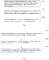
- FIG. 1 A gain adjustment control method provided by this embodiment is shown in Fig. 1 , which includes the following operations.
- energy of a full-bandwidth physical downlink shared channel (PDSCH) transmission signal in an intermediate frequency digital domain or a baseband digital domain is calculated according to a set calculation period.
- PDSCH physical downlink shared channel
- a specific value of the calculation period can be flexibly set according to a specific application scenario.
- the energy of the full-bandwidth PDSCH transmission signal may be calculated in the IF digital domain, or in the baseband digital domain, or be a combination of the energy of the full-bandwidth PDSCH transmission signal in the IF digital domain and the energy of the full-bandwidth PDSCH transmission signal in the baseband digital domain (for example, the energy of the full-bandwidth PDSCH transmission signal is calculated in the IF digital domain in some calculation periods, and the energy of the full-bandwidth PDSCH transmission signal is calculated in the baseband digital domain in other calculation periods).
- the calculation can be flexibly selected according to an application scenario.
- a gain control adjustment parameter is determined according to the calculated energy of the full-bandwidth PDSCH transmission signal.
- a gain of a receiver is controlled and adjusted according to the determined gain control adjustment parameter and a gain adjustment rule.
- the energy of the full-bandwidth PDSCH transmission signal is calculated in the IF digital domain for automatic gain adjustment.
- Fig. 2 the process of calculating the energy of the full-bandwidth PDSCH transmission signal in the IF digital domain is shown in Fig. 2 , which includes the following operations.
- an average power Pssb of a cell reference signal SSblock of k1 symbols for each respective antenna which schedules bandwidth of N Resource Blocks (RB) is calculated, where k1 is an integer greater than or equal to 2.
- k1 is an integer greater than or equal to 2.
- the value of k1 may be 4.
- other values can be flexibly selected according to the requirements.
- the value of Gu may also be set flexibly according to requirements, for example, the value of Gu may be 3db.
- the process also includes: measuring a power P csirssi_All of a channel quality measurement reference signal (CSIRS) for a cell, for example, measuring a single symbol power of a CSIRS signal sent by a 5G cell at the terminal receiver and adding a prediction protection value; measuring a service symbol PDSCH signal power P sym rssi_All , for example, measuring a single symbol power of a CSIRS signal sent by a 5G cell at the terminal receiver and adding a prediction protection value.
- CSIRS channel quality measurement reference signal
- a BFG value in a previous calculation period with a PDSCH signal can be adopted, or a BFG value can be set to 0 or other preset values.
- a currently adopted BFG value may also be time counted. If a duration t0 of the currently adopted BFG value is longer than a first preset duration T0, the currently adopted BFG value can be set as a preset BFG value, for example, preset to 0, or preset to other values as required.
- the process of determining a gain control adjustment parameter according to the calculated energy of the full-bandwidth PDSCH transmission signal includes: selecting a largest one from the calculated P pdsch_bf_All , P csi rssi_All and P sym rssi_All as the gain control adjustment parameter.
- the energy of the full-bandwidth PDSCH transmission signal is calculated in the baseband digital domain for automatic gain adjustment.
- Fig. 3 the process of calculating the energy of the full-bandwidth PDSCH transmission signal in the baseband digital domain is shown in Fig. 3 , which includes the following operations.
- an average strength Pssb-rssi of a received signal of SSblock of k2 symbols for each respective antenna which schedules bandwidth of N RB is calculated, where k2 is an integer greater than or equal to 2.
- k2 is an integer greater than or equal to 2.
- the value of k2 may be 4.
- other values can be flexibly selected according to the requirements.
- the value of Gu may also be set flexibly according to requirements, for example, the value of Gu may be 3db.
- the BFG value in a previous calculation period with PDSCH signal may be adopted, and the BFG value may also be set to 0 or other preset values.
- a currently adopted BFG value may also be time counted. If a duration t0 of the currently adopted BFG value is longer than a first preset duration T0, the currently adopted BFG value can be set as a preset BFG value, for example, preset to 0, or preset to other values as required.
- the process of determining a gain control adjustment parameter according to the calculated energy of the full-bandwidth PDSCH transmission signal includes: select a largest one from the calculated P ssb-rssi , P pdsch_bc_20rssi and P pdsch_bf_All as the gain control adjustment parameter.
- the gain of the receiver is controlled to be adjusted according to the determined gain control adjustment parameter and gain adjustment rule, as shown in Fig. 4 , which may include the following operations.
- a largest gain control adjustment parameter is selected from the gain control adjustment parameters acquired for the last H times, as a target gain control adjustment parameter X.
- H is an integer greater than or equal to 2, and it should be understood that a specific value of H may be flexibly set according to requirements, for example, it may be set to 2, 4, 8, 16, 32, 64, etc.
- the acquired target gain control adjustment parameter X can be stored in a stack for a subsequent selection and calling.
- the value of H may also be 1, that is, a gain control adjustment parameter acquired last time is directly used as the target gain control adjustment parameter.
- a gain of the receiver is controlled and adjusted according to the acquired X and a gain adjustment rule.
- the receiver can be set to have L gain levels, the energy values of adjacent gain levels have an overlapping area, and L is an integer greater than or equal to 2.
- a preset gain adjustment rule may include, but are not limited to:
- the process of determining the target gain level according to the target gain control adjustment parameter X may include, but is not limited to:
- the gain adjustment control method may also include, but is not limited to, at least one of the following.
- the gain level after the last switch is locked in a preset locking time period.
- the specific locking duration may be flexibly set according to specific application scenarios.
- the currently adopted gain level is switched to a next gain level which is lower than the currently adopted gain level.
- a largest one is selected from the gain control adjustment parameters acquired for the last 8 times, as the target gain control adjustment parameter.
- a preference is applied to an adaptive change within a current gain level, and the current level will be switched only if it is beyond a gain level range thereof.
- the overall control is based on a priority order from lower to higher gain levels.
- the target gain control adjustment parameter X selected for the first time is -47dBm
- the target gain control adjustment parameter X selected for the second time is -44dBm
- the target gain control adjustment parameter X selected for the third time is -47dBm
- the target gain control adjustment parameter X selected for the fourth time is -50dBm
- the level is switched from gain level two to gain level one
- the target gain control adjustment parameter X selected for the fifth time is -46dBm, the level is kept as gain level one.
- BFG maintains the last value.
- T1 is a threshold of a maximum number of upshifts, which is an adjustable value.
- 3db overlap between levels and BFG maintenance mechanism may be applied, so as to achieve an anti-jitter effect.
- a counter t0 may also be set. For the currently adopted BFG, if t0>T0, the adopted BFG value is considered invalid and set to 0.
- a counter t2 may also be set. If t2>T2 and a reference value is always in a certain level, and there is a level lower than the current level, the level will be downshifted.
- T0 and T2 are adjustable values
- T0 is a fiducial time for BFG
- T1 is a time duration to maintain a current level. Therefore, the target level can be downshifted when there is no PDSCH, and a risk caused by an estimation deviation of an overlapping area can be reduced.
- This embodiment provides a gain adjustment control device, which can be arranged in various communication devices (such as a receiver).
- a gain adjustment control device which can be arranged in various communication devices (such as a receiver).
- Fig. 6 which includes the following modules.
- An energy acquisition module 601 is configured to calculate energy of a full-bandwidth physical downlink shared channel (PDSCH) transmission signal in an intermediate frequency digital domain or a baseband digital domain according to a set calculation period.
- PDSCH physical downlink shared channel
- a specific value of the calculation period can be flexibly set according to a specific application scenario.
- the energy of the full-bandwidth PDSCH transmission signal may be calculated in the IF digital domain, or in the baseband digital domain, or be a combination of the energy of the full-bandwidth PDSCH transmission signal in the IF digital domain and the energy of the full-bandwidth PDSCH transmission signal in the baseband digital domain (for example, the energy of the full-bandwidth PDSCH transmission signal is calculated in the IF digital domain in some calculation periods, and the energy of the full-bandwidth PDSCH transmission signal is calculated in the baseband digital domain in other calculation periods).
- the calculation can be flexibly selected according to an application scenario.
- a gain control module 602 is configured to determine a gain control adjustment parameter according to the energy of the full-bandwidth PDSCH transmission signal, and control and adjust a gain of a receiver according to the determined gain control adjustment parameter and a gain adjustment rule.
- the energy of the full-bandwidth PDSCH transmission signal is calculated in the IF digital domain for automatic gain adjustment.
- the energy acquisition module 601 includes a cell reference signal SSblock measurement and prediction module 6011, which is configured for the terminal receiver to predict a maximum single symbol power of SSblock reference signal and shaping gain in the intermediate frequency digital domain.
- An example cell reference signal SSblock measurement and prediction module 6011 is configured to perform the following calculation processes.
- the value of k1 may be 4.
- M 10 ⁇ (log 10 273-log 10 X)
- the BFG value is a maximum power difference between the PDSCH signal and SSblock signal acquired on each antenna.
- the value of Gu may also be set flexibly according to requirements, for example, the value of Gu may be 3db.
- the energy acquisition module 601 also includes a channel quality measurement reference signal (CSIRS) measurement and prediction module 6012 which is configured to measure a power P csi rssi_All of a channel quality measurement reference signal (CSIRS) for a cell, for example, measuring a single symbol power of a CSIRS signal sent by a 5G cell at the terminal receiver and adding a prediction protection value.
- CSIRS channel quality measurement reference signal
- the energy acquisition module 601 also includes a service symbol maximum power measurement module 6013, which is configured to measure a service symbol PDSCH signal power P sym rssi_All , for example, measuring a single symbol power of a CSIRS signal sent by a 5G cell at the terminal receiver and adding a prediction protection value.
- a service symbol maximum power measurement module 6013 which is configured to measure a service symbol PDSCH signal power P sym rssi_All , for example, measuring a single symbol power of a CSIRS signal sent by a 5G cell at the terminal receiver and adding a prediction protection value.
- a BFG value in a previous calculation period with a PDSCH signal can be adopted, or a BFG value can be set to 0 or other preset values.
- a currently adopted BFG value may also be time counted. If a duration t0 of the currently adopted BFG value is longer than a first preset duration T0, the currently adopted BFG value can be set as a preset BFG value, for example, preset to 0, or preset to other values as required.
- the gain control module 602 also includes a maximum prediction selection module 6021, which is configured to select a largest one from the calculated P pdsch_bf_All , P csi rssi_All and P sym rssi_All as the gain control adjustment parameter.
- the energy of the full-bandwidth PDSCH transmission signal is calculated in the baseband digital domain for automatic gain adjustment.
- the value of Gu may also be set flexibly according to requirements, for example, the value of Gu may be 3db.
- the BFG value in a previous calculation period with PDSCH signal may be adopted, and the BFG value may also be set to 0 or other preset values.
- a currently adopted BFG value may also be time counted. If a duration t0 of the currently adopted BFG value is longer than a first preset duration T0, the currently adopted BFG value can be set as a preset BFG value, for example, preset to 0, or preset to other values as required.
- the baseband calculation adjustment and reference module 6014 is configured to select a largest one from the calculated P ssb-rssi , P pdsch_bc_20rssi and P pdsch_bf_All as the gain control adjustment parameter.
- the gain control module 602 in this embodiment also includes a table look-up and anti-jitter module 6022 and a downshift module 6023, where:
- the anti-jitter module 6022 is configured to: select a largest one from the gain control adjustment parameters acquired for the last H times, as a target gain control adjustment parameter X; control and adjust a gain of the receiver according to the acquired X and a gain adjustment rule.
- H is an integer greater than or equal to 2, in some examples, the value of H may also be 1, that is, a gain control adjustment parameter acquired last time is directly used as the target gain control adjustment parameter.
- the receiver can be set to have L gain levels, the energy values of adjacent gain levels have an overlapping area, and L is an integer greater than or equal to 2.
- a preset gain adjustment rule may include, but are not limited to:
- the process of determining the target gain level according to the target gain control adjustment parameter X may include, but is not limited to:
- the table lookup and anti-jitter module 6022 may also be configured to, in the second preset duration T1, when it is detected that the currently adopted gain level is switched to the target gain level for t1 times, and the target gain level is higher than the currently adopted gain level, lock the gain level after the last switch for a preset locking time period.
- the specific locking duration may be flexibly set according to specific application scenarios.
- the downshift module 6023 may be configured to, in the third preset duration T2, when it is detected that the currently adopted gain level has not been switched, and there is a gain level lower than the currently adopted gain level, switch the currently adopted gain level to a next gain level which is lower than the currently adopted gain level.
- the gain adjustment control device can calculate the energy of the full-bandwidth physical downlink channel PDSCH transmission signal in the IF digital domain or the baseband digital domain according to the set calculation period, then determine the gain control adjustment parameters according to the energy of the full-bandwidth PDSCH transmission signal, and control the adjustment of the gain of the receiver according to the determined gain control adjustment parameters and gain adjustment rules.
- This embodiment has better anti-interference performance and less influence from multi-path, and can better meet the application scenarios that require extremely high flatness of signals in time domain and frequency domain, such as the new 256QAM modulation and demodulation technology.
- This embodiment also provides a communication device, which can be used as various receivers, such as a terminal receiver in a 5G communication system.
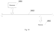
- the communication device includes a processor 1001, a memory 1002 and a communication bus 1003.
- the communication bus 1003 is configured to implement a communication between the processor 1001 and the memory 1002.
- the processor 1001 is configured to execute one or more computer program stored in the memory 1002 to implement the gain adjustment control methods of the above embodiments.
- This embodiment further provides a computer-readable storage medium that includes a volatile or non-volatile, removable or non-removable medium implemented in any method or technology for storing information (such as computer-readable instructions, data structures, computer program modules, or other data).
- the computer-readable storage media include, but are not limited to, random access memory (RAM), read-only memory (ROM), electrically erasable programmable read-only memory (EEPROM), flash memory or other memory technologies, compact disc read-only memory (CD-ROM), digital versatile disc (DVD) or other optical disc storage, cassettes, magnetic tapes, magnetic disc storage or other magnetic storage devices, or any other media that can be configured to store desired information and can be accessed by a computer.
- the computer-readable storage medium in this embodiment may be configured to store one or more computer programs executable by one or more processors to implement the gain adjustment control methods of the above embodiments.
- This embodiment further provides a computer program (or computer software), which may be distributed on a computer-readable medium and may be executed by a computing device to implement at least one step of the gain adjustment control methods of the above embodiments. In some cases, at least one of the steps shown or described may be performed in a different order from that described in the above embodiments.
- a computer program or computer software
- This embodiment further provides a computer program product including a computer-readable device on which a computer program as described above is stored.
- the computer-readable device may include the computer-readable storage medium as described above.
- the gain adjustment control method, device, apparatus and computer-readable storage medium provided by this embodiment can calculate the energy of the full-bandwidth physical downlink channel (PDSCH) transmission signal in the IF digital domain or the baseband digital domain according to the set calculation period, then determine the gain control adjustment parameters according to the energy of the full-bandwidth PDSCH transmission signal, and control the adjustment of the gain of the receiver.
- PDSCH physical downlink channel
- communication media typically contain computer-readable instructions, data structures, computer program modules or other data in a modulated data signal such as a carrier wave or other transmission mechanism, and may include any information delivery media. Therefore, the present disclosure is not limited to any particular combination of hardware and software.
Landscapes
- Engineering & Computer Science (AREA)
- Computer Networks & Wireless Communication (AREA)
- Signal Processing (AREA)
- Circuits Of Receivers In General (AREA)
Abstract
Description
- The present application is based on and claims the priority of
Chinese patent application No. 201910605821.0 filed on July 05, 2019 - The embodiments of the present disclosure relate to the field of communication, in particular to a gain adjustment control method, device, apparatus and computer-readable storage medium.
- In a radio receiver system, the strength of received signals may vary greatly, and the receiver must be able to demodulate these signals with different strengths correctly. In the fifth generation mobile communication system, Orthogonal Frequency Division Multiplexing (OFDM) terminal receiver is used. When 256QAM modulation is used, there is a high peak-to-average ratio, and the gap between the peak and the trough of the signal is close to more than ten decibels, which is a wide range. A higher-order modulation is more sensitive. It's very difficult for a receiver with constant gain to correctly demodulate a signal with such a wide energy range. In order to demodulate signals with different strengths correctly, the gain must be automatically adjusted according to the signal strength, such that the terminal receiver still has a high gain when receiving a weak signal and a low gain when receiving a strong signal. This may require an automatic gain control loop. In existing technologies, an automatic gain control loop is implemented by medium radio frequency analog signal processing in the RF link. Because analog signal processing may be easily affected by interference and multi-path, especially after long-distance transmission, the influence of some random noise may become significant due to noise accumulation, which leads to demodulation failure. Especially for the application scenarios that require extremely high flatness of signals in time domain and frequency domain, such as the new 256QAM modulation and demodulation technology, it's difficult for a gain control method based on analog domain in existing technologies to meet the demand.
- A gain adjustment control method, device, apparatus and computer-readable storage medium provided by the embodiments of the present disclosure can at least solve one of the technical problems in existing technologies to a certain extent, including providing a new gain adjustment control manner for the receiver, which can better meet the communication requirements.
- An embodiment of the present disclosure provides a gain adjustment control method, which includes: calculating energy of a full-bandwidth physical downlink shared channel (PDSCH) transmission signal in an intermediate frequency digital domain or a baseband digital domain according to a set calculation period; determining a gain control adjustment parameter according to the calculated energy of the full-bandwidth PDSCH transmission signal; and controlling and adjusting a gain of a receiver according to the determined gain control adjustment parameter and a gain adjustment rule.
- An embodiment of the present disclosure also provides a gain adjustment control device, which includes: an energy acquisition module, configured to calculate energy of a full-bandwidth physical downlink shared channel (PDSCH) transmission signal in an intermediate frequency digital domain or a baseband digital domain according to a set calculation period; and a gain control module, configured to determine a gain control adjustment parameter according to the energy of the full-bandwidth PDSCH transmission signal, and control and adjust a gain of a receiver according to the determined gain control adjustment parameter and a gain adjustment rule.
- An embodiment of the present disclosure also provides a communication apparatus, which includes a processor, a memory and a communication bus, wherein the communication bus is configured to connect the processor and the memory; and the processor is configured to execute a computer program stored in the memory to implement the gain adjustment control method as described above.
- An embodiment of the present disclosure also provides a computer-readable storage medium storing one or more computer programs executable by one or more processors to implement the gain adjustment control method as described above.
- Other features and corresponding beneficial effects of the present disclosure are explained in the subsequent description, and it should be understood that at least some of the beneficial effects become apparent from the description of the present disclosure.
-
-
Fig. 1 is a flowchart a gain adjustment control method according to example embodiment one of the present disclosure; -
Fig. 2 is a flowchart of calculating the energy of the full bandwidth PDSCH transmission signal in the intermediate frequency (IF) digital domain according to example embodiment one of the present disclosure; -
Fig. 3 is a flowchart of calculating the energy of the full bandwidth PDSCH transmission signal in the baseband digital domain according to example embodiment one of the present disclosure; -
Fig. 4 is a schematic diagram of the gain control flow of example embodiment one of the present disclosure; -
Fig. 5 is a schematic diagram of gain levels according to example embodiment one of the present disclosure; -
Fig. 6 is a structural diagram of a gain adjustment control device according to example embodiment two of the present disclosure; -
Fig. 7 is a schematic structural diagram of an energy acquisition module and a gain control module according to example embodiment two of the present disclosure; -
Fig. 8 is a schematic structural diagram of another energy acquisition module according to example embodiment two of the present disclosure; -
Fig. 9 is a schematic structural diagram of another gain control module according to example embodiment two of the present disclosure; and -
Fig. 10 is a structural diagram of a communication apparatus according to example embodiment three of the present disclosure. - In order to make the objective, technical schemes and advantages of the present disclosure clearly understood, the embodiments of the present disclosure will be further described in detail by means of several embodiments in conjunction with the accompanying drawings. It should be understood that the embodiments described here are intended only to explain the present disclosure and are not intended to limit the present disclosure.
- The gain adjustment control method provided by this embodiment can calculate the energy of the full-bandwidth physical downlink channel PDSCH transmission signal in the IF digital domain or the baseband digital domain according to the set calculation period, then determine the gain control adjustment parameters according to the energy of the full-bandwidth PDSCH transmission signal, and control the adjustment of the gain of the receiver according to the determined gain control adjustment parameters and gain adjustment rules. Compared with the existing technology, which realizes gain adjustment control based on medium radio frequency analog signal processing, this embodiment has better anti-interference performance and less influence from multi-path, and can better meet the application scenarios that require extremely high flatness of signals in time domain and frequency domain, such as the new 256QAM modulation and demodulation technology.
- A gain adjustment control method provided by this embodiment is shown in
Fig. 1 , which includes the following operations. - At S101, energy of a full-bandwidth physical downlink shared channel (PDSCH) transmission signal in an intermediate frequency digital domain or a baseband digital domain is calculated according to a set calculation period.
- In this embodiment, a specific value of the calculation period can be flexibly set according to a specific application scenario. In this embodiment, the energy of the full-bandwidth PDSCH transmission signal may be calculated in the IF digital domain, or in the baseband digital domain, or be a combination of the energy of the full-bandwidth PDSCH transmission signal in the IF digital domain and the energy of the full-bandwidth PDSCH transmission signal in the baseband digital domain (for example, the energy of the full-bandwidth PDSCH transmission signal is calculated in the IF digital domain in some calculation periods, and the energy of the full-bandwidth PDSCH transmission signal is calculated in the baseband digital domain in other calculation periods). The calculation can be flexibly selected according to an application scenario.
- At S102, a gain control adjustment parameter is determined according to the calculated energy of the full-bandwidth PDSCH transmission signal.
- At S103, a gain of a receiver is controlled and adjusted according to the determined gain control adjustment parameter and a gain adjustment rule.
- For the convenience of understanding, in an example of this embodiment, the energy of the full-bandwidth PDSCH transmission signal is calculated in the IF digital domain for automatic gain adjustment.
- In this example, the process of calculating the energy of the full-bandwidth PDSCH transmission signal in the IF digital domain is shown in
Fig. 2 , which includes the following operations. - At S201, an average power Pssb of a cell reference signal SSblock of k1 symbols for each respective antenna which schedules bandwidth of N Resource Blocks (RB) is calculated, where k1 is an integer greater than or equal to 2. In an example, the value of k1 may be 4. Of course, other values can be flexibly selected according to the requirements.
- At S202, according to the calculated Pssb and a power offset value per RB of PDSCH, energy Ppdsch_bc_20rssi of a PDSCH signal of N RB is calculated.
- At S203, the calculated Ppdsch_bc_20rssi is added with a bandwidth conversion coefficient M, a multi-antenna gain BFG value and a reserved protection value Gu to acquire the energy of the full-bandwidth PDSCH transmission signal Ppdschbf_All, that is:

- In this example, the process also includes: measuring a power Pcsirssi_All of a channel quality measurement reference signal (CSIRS) for a cell, for example, measuring a single symbol power of a CSIRS signal sent by a 5G cell at the terminal receiver and adding a prediction protection value; measuring a service symbol PDSCH signal power Psym rssi_All, for example, measuring a single symbol power of a CSIRS signal sent by a 5G cell at the terminal receiver and adding a prediction protection value.
- In this example, if there is no PDSCH signal in a current calculation period, a BFG value in a previous calculation period with a PDSCH signal can be adopted, or a BFG value can be set to 0 or other preset values.
- In some application scenarios, a currently adopted BFG value may also be time counted. If a duration t0 of the currently adopted BFG value is longer than a first preset duration T0, the currently adopted BFG value can be set as a preset BFG value, for example, preset to 0, or preset to other values as required.
- In this example, the process of determining a gain control adjustment parameter according to the calculated energy of the full-bandwidth PDSCH transmission signal includes: selecting a largest one from the calculated Ppdsch_bf_All, Pcsi rssi_All and Psym rssi_All as the gain control adjustment parameter.
- For the convenience of understanding, in an example of this embodiment, the energy of the full-bandwidth PDSCH transmission signal is calculated in the baseband digital domain for automatic gain adjustment.
- In this example, the process of calculating the energy of the full-bandwidth PDSCH transmission signal in the baseband digital domain is shown in
Fig. 3 , which includes the following operations. - At S301, an average strength Pssb-rssi of a received signal of SSblock of k2 symbols for each respective antenna which schedules bandwidth of N RB is calculated, where k2 is an integer greater than or equal to 2. In an example, the value of k2 may be 4. Of course, other values can be flexibly selected according to the requirements.
- At S302, according to the calculated Pssb-rssi and a power offset value per RB of PDSCH, energy Ppdsch_bc_20rssi of a PDSCH signal of N RB is calculated.
- At S303, the calculated Ppdsch_bc_20rssi is added with a bandwidth conversion coefficient M, a multi-antenna gain BFG value and a reserved protection value Gu to acquire the energy of the full-bandwidth PDSCH transmission signal Ppdschbf_All, that is:

- In this example, the BFG value in a previous calculation period with PDSCH signal may be adopted, and the BFG value may also be set to 0 or other preset values. In some application scenarios, a currently adopted BFG value may also be time counted. If a duration t0 of the currently adopted BFG value is longer than a first preset duration T0, the currently adopted BFG value can be set as a preset BFG value, for example, preset to 0, or preset to other values as required.
- In this example, the process of determining a gain control adjustment parameter according to the calculated energy of the full-bandwidth PDSCH transmission signal includes: select a largest one from the calculated Pssb-rssi, Ppdsch_bc_20rssi and Ppdsch_bf_All as the gain control adjustment parameter.
- In this embodiment, after the gain control adjustment parameter is determined according to the above example implementations, the gain of the receiver is controlled to be adjusted according to the determined gain control adjustment parameter and gain adjustment rule, as shown in
Fig. 4 , which may include the following operations. - At S401, a largest gain control adjustment parameter is selected from the gain control adjustment parameters acquired for the last H times, as a target gain control adjustment parameter X.
- H is an integer greater than or equal to 2, and it should be understood that a specific value of H may be flexibly set according to requirements, for example, it may be set to 2, 4, 8, 16, 32, 64, etc. In some examples, the acquired target gain control adjustment parameter X can be stored in a stack for a subsequent selection and calling.
- And it should be understood that in some examples, the value of H may also be 1, that is, a gain control adjustment parameter acquired last time is directly used as the target gain control adjustment parameter.
- At S402, a gain of the receiver is controlled and adjusted according to the acquired X and a gain adjustment rule.
- For example, in some application scenarios, for anti-jitter, the receiver can be set to have L gain levels, the energy values of adjacent gain levels have an overlapping area, and L is an integer greater than or equal to 2.
- In this application scenario, a preset gain adjustment rule may include, but are not limited to:
- determining a target gain level according to the target gain control adjustment parameter X;
- according to the target gain level acquired by a currently adopted gain level, switching a gain level.
- In this application scenario, the process of determining the target gain level according to the target gain control adjustment parameter X may include, but is not limited to:
- when the target gain control adjustment parameter X is located in an overlapping area of energy values of adjacent gain levels, and the currently adopted gain level is not in the adjacent gain level, determining that a lower gain level in the adjacent gain levels is the target gain level, based on a priority to a lower gain level; determining that the currently adopted gain level is the target gain level when the currently adopted gain level is in the adjacent gain level;
- when the target gain control adjustment parameter X falls into a range of energy values of a certain gain level and is located outside the overlapping area of energy values, determining that a gain level where X falls into is the target gain level.
- In this embodiment, the gain adjustment control method may also include, but is not limited to, at least one of the following.
- In the second preset duration T1, when it is detected that the currently adopted gain level is switched to the target gain level for t1 times, and the target gain level is higher than the currently adopted gain level, the gain level after the last switch is locked in a preset locking time period. The specific locking duration may be flexibly set according to specific application scenarios.
- In the third preset duration T2, when it is detected that the currently adopted gain level has not been switched, and there is a gain level lower than the currently adopted gain level, the currently adopted gain level is switched to a next gain level which is lower than the currently adopted gain level.
- For the convenience of understanding, this embodiment will be explained below by taking a terminal receiver in the 5G communication network as an example. Assuming that the terminal receiver has three gain levels, reference may be made to Table one as shown below and
Fig. 5 .Table one Gain levels Demarcation point Gain level one -45dbm ≥ X Gain level two -29dbm ≥ X ≥ -48dbm Gain level three X ≥ -32dbm - In this example, a largest one is selected from the gain control adjustment parameters acquired for the last 8 times, as the target gain control adjustment parameter. In this example, for the switching control of the gain levels, a preference is applied to an adaptive change within a current gain level, and the current level will be switched only if it is beyond a gain level range thereof. The overall control is based on a priority order from lower to higher gain levels. For example, assuming that the target gain control adjustment parameter X selected for the first time is -47dBm, it is determined that the currently adopted level is gain level one; assuming that the target gain control adjustment parameter X selected for the second time is -44dBm, it is determined to switch from gain level one to gain level two; assuming that the target gain control adjustment parameter X selected for the third time is -47dBm, it is determined to be still in gain level two; assuming that the target gain control adjustment parameter X selected for the fourth time is -50dBm, the level is switched from gain level two to gain level one; assuming that the target gain control adjustment parameter X selected for the fifth time is -46dBm, the level is kept as gain level one.
- In this example, if there is no service signal PDSCH next time, i.e., there is no BFG, then BFG maintains the last value.
- A counter t1 can be set to maintain a current level (that is, a gain level after the last switch is locked in a preset locking time period) if a number of upshift switching t1>T1 within a monitoring duration, and the locking time period is n ∗ monitoring duration t, where n=1,2,3, 'n' may be used as a maintenance coefficient.
- In this example, T1 is a threshold of a maximum number of upshifts, which is an adjustable value. In order to control a jitter effect caused by a upshift, 3db overlap between levels and BFG maintenance mechanism may be applied, so as to achieve an anti-jitter effect.
- In this embodiment, a counter t0 may also be set. For the currently adopted BFG, if t0>T0, the adopted BFG value is considered invalid and set to 0.
- In this embodiment, a counter t2 may also be set. If t2>T2 and a reference value is always in a certain level, and there is a level lower than the current level, the level will be downshifted.
- In this example, T0 and T2 are adjustable values, T0 is a fiducial time for BFG, and T1 is a time duration to maintain a current level. Therefore, the target level can be downshifted when there is no PDSCH, and a risk caused by an estimation deviation of an overlapping area can be reduced.
- This embodiment provides a gain adjustment control device, which can be arranged in various communication devices (such as a receiver). Reference is made to
Fig. 6 , which includes the following modules. - An
energy acquisition module 601 is configured to calculate energy of a full-bandwidth physical downlink shared channel (PDSCH) transmission signal in an intermediate frequency digital domain or a baseband digital domain according to a set calculation period. - In this embodiment, a specific value of the calculation period can be flexibly set according to a specific application scenario. In this embodiment, the energy of the full-bandwidth PDSCH transmission signal may be calculated in the IF digital domain, or in the baseband digital domain, or be a combination of the energy of the full-bandwidth PDSCH transmission signal in the IF digital domain and the energy of the full-bandwidth PDSCH transmission signal in the baseband digital domain (for example, the energy of the full-bandwidth PDSCH transmission signal is calculated in the IF digital domain in some calculation periods, and the energy of the full-bandwidth PDSCH transmission signal is calculated in the baseband digital domain in other calculation periods). The calculation can be flexibly selected according to an application scenario.
- A
gain control module 602 is configured to determine a gain control adjustment parameter according to the energy of the full-bandwidth PDSCH transmission signal, and control and adjust a gain of a receiver according to the determined gain control adjustment parameter and a gain adjustment rule. - For the convenience of understanding, in an example of this embodiment, the energy of the full-bandwidth PDSCH transmission signal is calculated in the IF digital domain for automatic gain adjustment.
- In this example, as shown in
Fig. 7 , theenergy acquisition module 601 includes a cell reference signal SSblock measurement andprediction module 6011, which is configured for the terminal receiver to predict a maximum single symbol power of SSblock reference signal and shaping gain in the intermediate frequency digital domain. An example cell reference signal SSblock measurement andprediction module 6011 is configured to perform the following calculation processes. - The cell reference signal SSblock measurement and
prediction module 6011 is configured to calculate average power Pssb of a cell reference signal SSblock of k1 symbols for each respective antenna which schedules bandwidth of N Resource Blocks (RB); according to the calculated Pssb and a power offset value per RB of PDSCH, calculate energy Ppdsch_bc_20rssi of a PDSCH signal of N RB; add the calculated Ppdsch_bc_20rssi with a bandwidth conversion coefficient M, a multi-antenna gain BFG value and a reserved protection value Gu to acquire the energy of the full-bandwidth PDSCH transmission signal Ppdschbf_All, that is:
- In this example, the
energy acquisition module 601 also includes a channel quality measurement reference signal (CSIRS) measurement and prediction module 6012 which is configured to measure a power Pcsi rssi_All of a channel quality measurement reference signal (CSIRS) for a cell, for example, measuring a single symbol power of a CSIRS signal sent by a 5G cell at the terminal receiver and adding a prediction protection value. - The
energy acquisition module 601 also includes a service symbol maximumpower measurement module 6013, which is configured to measure a service symbol PDSCH signal power Psym rssi_All, for example, measuring a single symbol power of a CSIRS signal sent by a 5G cell at the terminal receiver and adding a prediction protection value. - In this example, if there is no PDSCH signal in a current calculation period, a BFG value in a previous calculation period with a PDSCH signal can be adopted, or a BFG value can be set to 0 or other preset values.
- In some application scenarios, a currently adopted BFG value may also be time counted. If a duration t0 of the currently adopted BFG value is longer than a first preset duration T0, the currently adopted BFG value can be set as a preset BFG value, for example, preset to 0, or preset to other values as required.
- The
gain control module 602 also includes a maximumprediction selection module 6021, which is configured to select a largest one from the calculated Ppdsch_bf_All, Pcsi rssi_All and Psym rssi_All as the gain control adjustment parameter. - For the convenience of understanding, in an example of this embodiment, the energy of the full-bandwidth PDSCH transmission signal is calculated in the baseband digital domain for automatic gain adjustment.
- In this example, as shown in
Fig. 8 , theenergy acquisition module 601 includes a baseband calculation adjustment and reference module 6014, which is configured to calculate an average strength Pssb-rssi of a received signal of SSblock of k2 symbols for each respective antenna which schedules bandwidth of N RB; according to the calculated Pssb-rssi and a power offset value per RB of PDSCH, calculate energy Ppdsch_bc_20rssi of a PDSCH signal of N RB; add the calculated Ppdsch_bc_20rssi with a bandwidth conversion coefficient M, a multi-antenna gain BFG value and a reserved protection value Gu to acquire the energy of the full-bandwidth PDSCH transmission signal Ppdsch_bf_All, that is:
- In this example, the BFG value in a previous calculation period with PDSCH signal may be adopted, and the BFG value may also be set to 0 or other preset values. In some application scenarios, a currently adopted BFG value may also be time counted. If a duration t0 of the currently adopted BFG value is longer than a first preset duration T0, the currently adopted BFG value can be set as a preset BFG value, for example, preset to 0, or preset to other values as required.
- In this example, the baseband calculation adjustment and reference module 6014 is configured to select a largest one from the calculated Pssb-rssi, Ppdsch_bc_20rssi and Ppdsch_bf_All as the gain control adjustment parameter.
- As shown in
Fig. 9 , thegain control module 602 in this embodiment also includes a table look-up andanti-jitter module 6022 and adownshift module 6023, where:
Theanti-jitter module 6022 is configured to: select a largest one from the gain control adjustment parameters acquired for the last H times, as a target gain control adjustment parameter X; control and adjust a gain of the receiver according to the acquired X and a gain adjustment rule. H is an integer greater than or equal to 2, in some examples, the value of H may also be 1, that is, a gain control adjustment parameter acquired last time is directly used as the target gain control adjustment parameter. - For example, in some application scenarios, for anti-jitter, the receiver can be set to have L gain levels, the energy values of adjacent gain levels have an overlapping area, and L is an integer greater than or equal to 2.
- In this application scenario, a preset gain adjustment rule may include, but are not limited to:
- determining a target gain level according to the target gain control adjustment parameter X;
- according to the target gain level acquired by a currently adopted gain level, switching a gain level.
- In this application scenario, the process of determining the target gain level according to the target gain control adjustment parameter X may include, but is not limited to:
- when the target gain control adjustment parameter X is located in the overlapping area of energy values of adjacent gain levels, and the currently adopted gain level is not in the adjacent gain level, determining that a lower gain level in the adjacent gain levels is the target gain level, based on a priority to a lower gain level; determining that the currently adopted gain level is the target gain level when the currently adopted gain level is in the adjacent gain level;
- when the target gain control adjustment parameter X falls into a range of energy values of a certain gain level and is located outside the overlapping area of energy values, determining that a gain level where X falls into is the target gain level.
- In this embodiment, the table lookup and
anti-jitter module 6022 may also be configured to, in the second preset duration T1, when it is detected that the currently adopted gain level is switched to the target gain level for t1 times, and the target gain level is higher than the currently adopted gain level, lock the gain level after the last switch for a preset locking time period. The specific locking duration may be flexibly set according to specific application scenarios. - The
downshift module 6023 may be configured to, in the third preset duration T2, when it is detected that the currently adopted gain level has not been switched, and there is a gain level lower than the currently adopted gain level, switch the currently adopted gain level to a next gain level which is lower than the currently adopted gain level. - The gain adjustment control device provided by this embodiment can calculate the energy of the full-bandwidth physical downlink channel PDSCH transmission signal in the IF digital domain or the baseband digital domain according to the set calculation period, then determine the gain control adjustment parameters according to the energy of the full-bandwidth PDSCH transmission signal, and control the adjustment of the gain of the receiver according to the determined gain control adjustment parameters and gain adjustment rules. This embodiment has better anti-interference performance and less influence from multi-path, and can better meet the application scenarios that require extremely high flatness of signals in time domain and frequency domain, such as the new 256QAM modulation and demodulation technology.
- This embodiment also provides a communication device, which can be used as various receivers, such as a terminal receiver in a 5G communication system. As shown in
Fig. 10 , the communication device includes aprocessor 1001, amemory 1002 and acommunication bus 1003. - The
communication bus 1003 is configured to implement a communication between theprocessor 1001 and thememory 1002. - In an example, the
processor 1001 is configured to execute one or more computer program stored in thememory 1002 to implement the gain adjustment control methods of the above embodiments. - This embodiment further provides a computer-readable storage medium that includes a volatile or non-volatile, removable or non-removable medium implemented in any method or technology for storing information (such as computer-readable instructions, data structures, computer program modules, or other data). The computer-readable storage media include, but are not limited to, random access memory (RAM), read-only memory (ROM), electrically erasable programmable read-only memory (EEPROM), flash memory or other memory technologies, compact disc read-only memory (CD-ROM), digital versatile disc (DVD) or other optical disc storage, cassettes, magnetic tapes, magnetic disc storage or other magnetic storage devices, or any other media that can be configured to store desired information and can be accessed by a computer.
- In an example, the computer-readable storage medium in this embodiment may be configured to store one or more computer programs executable by one or more processors to implement the gain adjustment control methods of the above embodiments.
- This embodiment further provides a computer program (or computer software), which may be distributed on a computer-readable medium and may be executed by a computing device to implement at least one step of the gain adjustment control methods of the above embodiments. In some cases, at least one of the steps shown or described may be performed in a different order from that described in the above embodiments.
- This embodiment further provides a computer program product including a computer-readable device on which a computer program as described above is stored. In this embodiment, the computer-readable device may include the computer-readable storage medium as described above.
- The gain adjustment control method, device, apparatus and computer-readable storage medium provided by this embodiment can calculate the energy of the full-bandwidth physical downlink channel (PDSCH) transmission signal in the IF digital domain or the baseband digital domain according to the set calculation period, then determine the gain control adjustment parameters according to the energy of the full-bandwidth PDSCH transmission signal, and control the adjustment of the gain of the receiver. Compared with the existing technology, which realizes gain adjustment control based on medium radio frequency analog signal processing, this embodiment has better anti-interference performance and less influence from multi-path, and can better meet the application scenarios that require extremely high flatness of signals in time domain and frequency domain.
- As can be seen, it should be understood by those having ordinary skills in the art that all or some of the steps in the methods disclosed above, functional modules/units in the systems and devices disclosed above may be implemented as software (which may be implemented by computer program code executable by a computing device), firmware, hardware, and appropriate combinations thereof. In the hardware implementation, the division between functional modules/units mentioned in the above description does not necessarily correspond to the division of physical components; for example, a physical component may have multiple functions, or a function or step may be performed cooperatively by several physical components. Some or all of the physical components may be implemented as software executed by a processor, such as a central processing unit, a digital signal processor or a microprocessor, or as hardware, or as an integrated circuit, such as an application specific integrated circuit.
- Furthermore, it is well known to those having ordinary skills in the art that communication media typically contain computer-readable instructions, data structures, computer program modules or other data in a modulated data signal such as a carrier wave or other transmission mechanism, and may include any information delivery media. Therefore, the present disclosure is not limited to any particular combination of hardware and software.
- The foregoing is a detailed description of the embodiments of the present disclosure in conjunction with particular implementations, and specific implementations of the present disclosure should not be construed as being limited to the description. For those having ordinary skills in the art to which the present disclosure pertains, without departing from the concept of the present disclosure, several deductions or substitutions can be made, which should be regarded as falling within the scope of the present disclosure.
Claims (13)
- A gain adjustment control method, comprising:calculating energy of a full-bandwidth physical downlink shared channel (PDSCH) transmission signal in an intermediate frequency digital domain or a baseband digital domain according to a set calculation period;determining a gain control adjustment parameter according to the calculated energy of the full-bandwidth PDSCH transmission signal; andcontrolling and adjusting a gain of a receiver according to the determined gain control adjustment parameter and a gain adjustment rule.
- The gain adjustment control method of claim 1, wherein calculating the energy of the full-bandwidth PDSCH transmission signal in the intermediate frequency digital domain comprises:calculating average power Pssb of a cell reference signal SSblock of k1 symbols for a respective antenna which schedules bandwidth of N Resource Blocks (RB), where k1 is an integer greater than or equal to 2;calculating energy Ppdsch_bc_20rssi of a PDSCH signal of N RB, according to the Pssb and a power offset value per RB of PDSCH; andadding Ppdsch_bc_20rssi with a bandwidth conversion coefficient M, a multi-antenna gain BFG value and a reserved protection value Gu to acquire the energy of the full-bandwidth PDSCH transmission signal Ppdschbf_All, where M=10∗(log10273-log10X), the BFG value is a maximum power difference between the PDSCH signal and SSblock signal acquired on the respective antenna.
- The gain adjustment control method of claim 2, further comprising:measuring a power Pcsi rssi_All of a channel quality measurement reference signal (CSIRS) for a cell, and measuring a service symbol PDSCH signal power Psym rssi_All; anddetermining a gain control adjustment parameter according to the energy of the full-bandwidth PDSCH transmission signal comprising:
selecting a largest one from Ppdsch_bf_All, Pcsi rssi_All and Psym rssi_All as the gain control adjustment parameter. - The gain adjustment control method of claim 1, wherein calculating the energy of the full-bandwidth PDSCH transmission signal in the baseband digital domain comprises:calculating an average strength Pssb-rssi of a received signal of SSblock of k2 symbols for a respective antenna which schedules bandwidth of N RB, where k1 is an integer greater than or equal to 2;calculating energy Ppdsch_bc_20rssi of a PDSCH signal of N RB, according to Pssb-rssi and a power offset value per RB of PDSCH; andadding Ppdsch_bc_20rssi with a bandwidth conversion coefficient M, a multi-antenna gain BFG value and a reserved protection value Gu to acquire the energy of the full-bandwidth PDSCH transmission signal Ppdsch_bf_All.
- The gain adjustment control method of claim 4, wherein determining a gain control adjustment parameter according to the energy of the full-bandwidth PDSCH transmission signal comprises:
selecting a largest one from Pssb-rssi, Ppdsch_bc_20rssi and Ppdsch_bf_All as the gain control adjustment parameter. - The gain adjustment control method of claim 2 or 4, wherein the value Gu is 3db.
- The gain adjustment control method of claim 2 or 4, wherein,in response to an absence of PDSCH signal in a current calculation period, a BFG value in a previous calculation period which involving a PDSCH signal is adopted; andin response to a duration of a currently adopted BFG value being longer than a first preset duration, the currently adopted BFG value is set as a preset BFG value.
- The gain adjustment control method of any one of claims 1 to 5, wherein controlling and adjusting a gain of a receiver according to the determined gain control adjustment parameter and a gain adjustment rule comprises:selecting a largest one from gain control adjustment parameters acquired for last H times, as a target gain control adjustment parameter X; andcontrolling and adjusting a gain of the receiver according to the target gain control adjustment parameter X and a gain adjustment rule.
- The gain adjustment control method of claim 8, wherein,the receiver has L gain levels, energy values of adjacent gain levels have an overlapping area, and L is an integer greater than or equal to 2; andthe gain adjustment rule comprises:determining a target gain level according to the target gain control adjustment parameter X; andswitching a gain level, according to the target gain level and the currently adopted gain level;wherein determining a target gain level according to the target gain control adjustment parameter X comprises:when the target gain control adjustment parameter X is located in the overlapping area of energy values of adjacent gain levels, and the currently adopted gain level is not in the adjacent gain levels, determining that a lower gain level in the adjacent gain levels is the target gain level; when the currently adopted gain level is in the adjacent gain levels, determining that the currently adopted gain level is the target gain level; andwhen the target gain control adjustment parameter X falls into a range of energy values of a certain gain level and is located outside the overlapping area of energy values, determining that a gain level where X falls into is the target gain level.
- The gain adjustment control method of claim 9, further comprising at least one of:in a second preset duration, in response to a detection that the currently adopted gain level is switched to the target gain level for t1 times, and the target gain level is higher than the currently adopted gain level, locking the gain level after a last switching within a preset locking time period; andin a third preset duration, in response to a detection that the currently adopted gain level has not been switched, and there is a gain level lower than the currently adopted gain level, switching the currently adopted gain level to a next gain level which is lower than the currently adopted gain level.
- A gain adjustment control device, comprising:an energy acquisition module, configured to calculate energy of a full-bandwidth physical downlink shared channel (PDSCH) transmission signal in an intermediate frequency digital domain or a baseband digital domain according to a set calculation period; anda gain control module, configured to determine a gain control adjustment parameter according to the energy of the full-bandwidth PDSCH transmission signal, and control and adjust a gain of a receiver according to the determined gain control adjustment parameter and a gain adjustment rule.
- A communication apparatus, comprising:a memory storing a computer program;a processor, configured to execute the computer program to implement the gain adjustment control method of any one of claims 1 to 10; anda communication bus, configured to connect the processor and the memory.
- A computer-readable storage medium storing at least one computer program executable by at least one processor to implement the gain adjustment control method of any one of claims 1 to 10.
Applications Claiming Priority (2)
| Application Number | Priority Date | Filing Date | Title |
|---|---|---|---|
| CN201910605821.0A CN112187300B (en) | 2019-07-05 | 2019-07-05 | Gain adjustment control method, device, device, and computer-readable storage medium |
| PCT/CN2020/091034 WO2021004164A1 (en) | 2019-07-05 | 2020-05-19 | Gain adjustment control method, device and apparatus, and computer readable storage medium |
Publications (3)
| Publication Number | Publication Date |
|---|---|
| EP3993276A1 true EP3993276A1 (en) | 2022-05-04 |
| EP3993276A4 EP3993276A4 (en) | 2022-08-31 |
| EP3993276B1 EP3993276B1 (en) | 2024-10-16 |
Family
ID=73914642
Family Applications (1)
| Application Number | Title | Priority Date | Filing Date |
|---|---|---|---|
| EP20837132.8A Active EP3993276B1 (en) | 2019-07-05 | 2020-05-19 | Gain adjustment control method, device and apparatus, and computer readable storage medium |
Country Status (5)
| Country | Link |
|---|---|
| US (1) | US12245170B2 (en) |
| EP (1) | EP3993276B1 (en) |
| JP (1) | JP7319451B2 (en) |
| CN (1) | CN112187300B (en) |
| WO (1) | WO2021004164A1 (en) |
Families Citing this family (2)
| Publication number | Priority date | Publication date | Assignee | Title |
|---|---|---|---|---|
| CN114554583B (en) * | 2022-04-01 | 2024-06-07 | 上海星思半导体有限责任公司 | Signal power adjustment method and device and electronic equipment |
| CN115941411B (en) * | 2022-07-04 | 2023-07-28 | 上海星思半导体有限责任公司 | Signal processing method, device, electronic equipment and storage medium |
Family Cites Families (14)
| Publication number | Priority date | Publication date | Assignee | Title |
|---|---|---|---|---|
| US8605836B2 (en) | 2005-03-11 | 2013-12-10 | Qualcomm Incorporated | Automatic gain control for a wireless receiver |
| WO2008009574A1 (en) | 2006-07-20 | 2008-01-24 | Telefonaktiebolaget L M Ericsson (Publ) | Radio receiver |
| US8149964B2 (en) | 2007-01-05 | 2012-04-03 | Qualcomm, Incorporated | Symbol scaling with automatic gain control for wireless communication |
| US9603097B2 (en) | 2009-06-29 | 2017-03-21 | Qualcomm Incorporated | Device, method, and apparatus for offline discontinuous reception (DRX) processing with online triggers in cellular systems |
| CN102594275A (en) * | 2011-01-07 | 2012-07-18 | 中国科学院微电子研究所 | Apparatus and method for automatic gain control |
| WO2011100920A2 (en) | 2011-04-13 | 2011-08-25 | 华为技术有限公司 | Method and device for automatic gain adjustment in wireless receiver |
| US8830859B2 (en) * | 2012-05-10 | 2014-09-09 | Blackberry Limited | Power based gain control adjustment |
| EP2663140A1 (en) | 2012-05-10 | 2013-11-13 | BlackBerry Limited | Power based gain control adjustment |
| US8948611B1 (en) | 2012-05-31 | 2015-02-03 | Maxim Integrated Products, Inc. | I/R receiver with duty cycle synchronized power reduction |
| CN104469925B (en) * | 2014-11-28 | 2017-12-22 | 深圳市海思半导体有限公司 | A kind of frequency domain auto gain control method and device |
| CN104703272A (en) | 2015-02-10 | 2015-06-10 | 苏州思源通科技有限公司 | Automatic gain control method suitable for OFDM system |
| CN106612533B (en) * | 2015-10-26 | 2019-12-17 | 瑞昱半导体股份有限公司 | Communication receiver and its automatic gain control method |
| CN108462977B (en) * | 2017-02-21 | 2020-07-31 | 深圳市中兴微电子技术有限公司 | A kind of automatic gain control method and device |
| CN107086859B (en) | 2017-04-17 | 2020-11-20 | 东南大学 | Digital Automatic Gain Control Circuit for Wireless Communication Receiver |
-
2019
- 2019-07-05 CN CN201910605821.0A patent/CN112187300B/en active Active
-
2020
- 2020-05-19 JP JP2022500632A patent/JP7319451B2/en active Active
- 2020-05-19 US US17/624,728 patent/US12245170B2/en active Active
- 2020-05-19 WO PCT/CN2020/091034 patent/WO2021004164A1/en not_active Ceased
- 2020-05-19 EP EP20837132.8A patent/EP3993276B1/en active Active
Also Published As
| Publication number | Publication date |
|---|---|
| CN112187300B (en) | 2023-06-06 |
| EP3993276A4 (en) | 2022-08-31 |
| US20220256482A1 (en) | 2022-08-11 |
| JP7319451B2 (en) | 2023-08-01 |
| US12245170B2 (en) | 2025-03-04 |
| JP2022540103A (en) | 2022-09-14 |
| CN112187300A (en) | 2021-01-05 |
| EP3993276B1 (en) | 2024-10-16 |
| WO2021004164A1 (en) | 2021-01-14 |
Similar Documents
| Publication | Publication Date | Title |
|---|---|---|
| EP3836438B1 (en) | Power control method and device, and method and device for determining target receiving power | |
| US8977311B2 (en) | Method and arrangement for reducing interference in a wireless communication network | |
| US7050760B2 (en) | Terminal station controls transmission power of a base station | |
| EP3641411A1 (en) | Method and device for determining transmission power, and terminal and storage medium | |
| US8830859B2 (en) | Power based gain control adjustment | |
| EP3783966A1 (en) | Power control method and apparatus, base station, terminal, and computer-readable storage medium | |
| US9544862B2 (en) | Method and device for performing automatic gain control | |
| US20090163167A1 (en) | Automatic gain control for beamformed signals | |
| US20070270154A1 (en) | Apparatus and method for scheduling using channel varation in a broadband wireless communication system | |
| EP3993276B1 (en) | Gain adjustment control method, device and apparatus, and computer readable storage medium | |
| EP3079415A1 (en) | Method, device and system for suppressing uplink background noise in indoor distributed system | |
| US11522737B2 (en) | Systems and methods for automatic level control | |
| CA2582366C (en) | Mitigating intermodulation interference using channel power estimation and attenuation in a two-way radio communications system | |
| JP5440464B2 (en) | Base station, transmission parameter control method | |
| EP3925316B1 (en) | Power control parameters indication | |
| WO2014098737A1 (en) | Tracking received power in wireless communications | |
| US7418242B2 (en) | Transmission device and gain control method | |
| US20200099489A1 (en) | Method and apparatus for configuring reference signal of a wireless communication system | |
| US20170111204A1 (en) | Communication Receiving End and Auto Gain Control Method Thereof | |
| US11146373B2 (en) | Method and apparatus for reference signal configuration of a wireless communication system | |
| EP3968705A1 (en) | Gain control method and device, and computer-readable storage medium | |
| EP4578125B1 (en) | Handling of cqi reports in the presence of prb blocking | |
| US8244196B2 (en) | Apparatus and method for estimating noise and interference power in a communication system | |
| KR20260005678A (en) | A wireless communication device for controlling the received power of heterogeneous signals and a method of operating the device | |
| WO2015023297A1 (en) | Method and apparatus for mitigating relative-phase discontinuity |
Legal Events
| Date | Code | Title | Description |
|---|---|---|---|
| STAA | Information on the status of an ep patent application or granted ep patent |
Free format text: STATUS: THE INTERNATIONAL PUBLICATION HAS BEEN MADE |
|
| PUAI | Public reference made under article 153(3) epc to a published international application that has entered the european phase |
Free format text: ORIGINAL CODE: 0009012 |
|
| STAA | Information on the status of an ep patent application or granted ep patent |
Free format text: STATUS: REQUEST FOR EXAMINATION WAS MADE |
|
| 17P | Request for examination filed |
Effective date: 20220125 |
|
| AK | Designated contracting states |
Kind code of ref document: A1 Designated state(s): AL AT BE BG CH CY CZ DE DK EE ES FI FR GB GR HR HU IE IS IT LI LT LU LV MC MK MT NL NO PL PT RO RS SE SI SK SM TR |
|
| A4 | Supplementary search report drawn up and despatched |
Effective date: 20220803 |
|
| RIC1 | Information provided on ipc code assigned before grant |
Ipc: H03G 3/30 20060101ALI20220728BHEP Ipc: H04B 1/16 20060101ALI20220728BHEP Ipc: H04B 1/10 20060101AFI20220728BHEP |
|
| DAV | Request for validation of the european patent (deleted) | ||
| DAX | Request for extension of the european patent (deleted) | ||
| REG | Reference to a national code |
Ref country code: DE Ref legal event code: R079 Free format text: PREVIOUS MAIN CLASS: H04B0001120000 Ipc: H04B0001100000 Ref document number: 602020039671 Country of ref document: DE |
|
| RIC1 | Information provided on ipc code assigned before grant |
Ipc: H03G 3/30 20060101ALI20221031BHEP Ipc: H04B 1/16 20060101ALI20221031BHEP Ipc: H04B 1/10 20060101AFI20221031BHEP |
|
| GRAP | Despatch of communication of intention to grant a patent |
Free format text: ORIGINAL CODE: EPIDOSNIGR1 |
|
| STAA | Information on the status of an ep patent application or granted ep patent |
Free format text: STATUS: GRANT OF PATENT IS INTENDED |
|
| INTG | Intention to grant announced |
Effective date: 20240726 |
|
| GRAS | Grant fee paid |
Free format text: ORIGINAL CODE: EPIDOSNIGR3 |
|
| GRAA | (expected) grant |
Free format text: ORIGINAL CODE: 0009210 |
|
| STAA | Information on the status of an ep patent application or granted ep patent |
Free format text: STATUS: THE PATENT HAS BEEN GRANTED |
|
| AK | Designated contracting states |
Kind code of ref document: B1 Designated state(s): AL AT BE BG CH CY CZ DE DK EE ES FI FR GB GR HR HU IE IS IT LI LT LU LV MC MK MT NL NO PL PT RO RS SE SI SK SM TR |
|
| REG | Reference to a national code |
Ref country code: GB Ref legal event code: FG4D |
|
| REG | Reference to a national code |
Ref country code: CH Ref legal event code: EP Ref country code: DE Ref legal event code: R096 Ref document number: 602020039671 Country of ref document: DE |
|
| REG | Reference to a national code |
Ref country code: IE Ref legal event code: FG4D |
|
| REG | Reference to a national code |
Ref country code: LT Ref legal event code: MG9D |
|
| REG | Reference to a national code |
Ref country code: NL Ref legal event code: MP Effective date: 20241016 |
|
| REG | Reference to a national code |
Ref country code: AT Ref legal event code: MK05 Ref document number: 1733766 Country of ref document: AT Kind code of ref document: T Effective date: 20241016 |
|
| PG25 | Lapsed in a contracting state [announced via postgrant information from national office to epo] |
Ref country code: NL Free format text: LAPSE BECAUSE OF FAILURE TO SUBMIT A TRANSLATION OF THE DESCRIPTION OR TO PAY THE FEE WITHIN THE PRESCRIBED TIME-LIMIT Effective date: 20241016 |
|
| PG25 | Lapsed in a contracting state [announced via postgrant information from national office to epo] |
Ref country code: NL Free format text: LAPSE BECAUSE OF FAILURE TO SUBMIT A TRANSLATION OF THE DESCRIPTION OR TO PAY THE FEE WITHIN THE PRESCRIBED TIME-LIMIT Effective date: 20241016 |
|
| PG25 | Lapsed in a contracting state [announced via postgrant information from national office to epo] |
Ref country code: IS Free format text: LAPSE BECAUSE OF FAILURE TO SUBMIT A TRANSLATION OF THE DESCRIPTION OR TO PAY THE FEE WITHIN THE PRESCRIBED TIME-LIMIT Effective date: 20250216 Ref country code: HR Free format text: LAPSE BECAUSE OF FAILURE TO SUBMIT A TRANSLATION OF THE DESCRIPTION OR TO PAY THE FEE WITHIN THE PRESCRIBED TIME-LIMIT Effective date: 20241016 Ref country code: PT Free format text: LAPSE BECAUSE OF FAILURE TO SUBMIT A TRANSLATION OF THE DESCRIPTION OR TO PAY THE FEE WITHIN THE PRESCRIBED TIME-LIMIT Effective date: 20250217 |
|
| PG25 | Lapsed in a contracting state [announced via postgrant information from national office to epo] |
Ref country code: FI Free format text: LAPSE BECAUSE OF FAILURE TO SUBMIT A TRANSLATION OF THE DESCRIPTION OR TO PAY THE FEE WITHIN THE PRESCRIBED TIME-LIMIT Effective date: 20241016 |
|
| PG25 | Lapsed in a contracting state [announced via postgrant information from national office to epo] |
Ref country code: BG Free format text: LAPSE BECAUSE OF FAILURE TO SUBMIT A TRANSLATION OF THE DESCRIPTION OR TO PAY THE FEE WITHIN THE PRESCRIBED TIME-LIMIT Effective date: 20241016 |
|
| PG25 | Lapsed in a contracting state [announced via postgrant information from national office to epo] |
Ref country code: ES Free format text: LAPSE BECAUSE OF FAILURE TO SUBMIT A TRANSLATION OF THE DESCRIPTION OR TO PAY THE FEE WITHIN THE PRESCRIBED TIME-LIMIT Effective date: 20241016 |
|
| PG25 | Lapsed in a contracting state [announced via postgrant information from national office to epo] |
Ref country code: NO Free format text: LAPSE BECAUSE OF FAILURE TO SUBMIT A TRANSLATION OF THE DESCRIPTION OR TO PAY THE FEE WITHIN THE PRESCRIBED TIME-LIMIT Effective date: 20250116 |
|
| PG25 | Lapsed in a contracting state [announced via postgrant information from national office to epo] |
Ref country code: LV Free format text: LAPSE BECAUSE OF FAILURE TO SUBMIT A TRANSLATION OF THE DESCRIPTION OR TO PAY THE FEE WITHIN THE PRESCRIBED TIME-LIMIT Effective date: 20241016 Ref country code: GR Free format text: LAPSE BECAUSE OF FAILURE TO SUBMIT A TRANSLATION OF THE DESCRIPTION OR TO PAY THE FEE WITHIN THE PRESCRIBED TIME-LIMIT Effective date: 20250117 Ref country code: AT Free format text: LAPSE BECAUSE OF FAILURE TO SUBMIT A TRANSLATION OF THE DESCRIPTION OR TO PAY THE FEE WITHIN THE PRESCRIBED TIME-LIMIT Effective date: 20241016 |
|
| PG25 | Lapsed in a contracting state [announced via postgrant information from national office to epo] |
Ref country code: PL Free format text: LAPSE BECAUSE OF FAILURE TO SUBMIT A TRANSLATION OF THE DESCRIPTION OR TO PAY THE FEE WITHIN THE PRESCRIBED TIME-LIMIT Effective date: 20241016 |
|
| PG25 | Lapsed in a contracting state [announced via postgrant information from national office to epo] |
Ref country code: RS Free format text: LAPSE BECAUSE OF FAILURE TO SUBMIT A TRANSLATION OF THE DESCRIPTION OR TO PAY THE FEE WITHIN THE PRESCRIBED TIME-LIMIT Effective date: 20250116 |
|
| PG25 | Lapsed in a contracting state [announced via postgrant information from national office to epo] |
Ref country code: SM Free format text: LAPSE BECAUSE OF FAILURE TO SUBMIT A TRANSLATION OF THE DESCRIPTION OR TO PAY THE FEE WITHIN THE PRESCRIBED TIME-LIMIT Effective date: 20241016 |
|
| PGFP | Annual fee paid to national office [announced via postgrant information from national office to epo] |
Ref country code: DE Payment date: 20250521 Year of fee payment: 6 |
|
| PG25 | Lapsed in a contracting state [announced via postgrant information from national office to epo] |
Ref country code: DK Free format text: LAPSE BECAUSE OF FAILURE TO SUBMIT A TRANSLATION OF THE DESCRIPTION OR TO PAY THE FEE WITHIN THE PRESCRIBED TIME-LIMIT Effective date: 20241016 |
|
| REG | Reference to a national code |
Ref country code: DE Ref legal event code: R097 Ref document number: 602020039671 Country of ref document: DE |
|
| PG25 | Lapsed in a contracting state [announced via postgrant information from national office to epo] |
Ref country code: EE Free format text: LAPSE BECAUSE OF FAILURE TO SUBMIT A TRANSLATION OF THE DESCRIPTION OR TO PAY THE FEE WITHIN THE PRESCRIBED TIME-LIMIT Effective date: 20241016 |
|
| PGFP | Annual fee paid to national office [announced via postgrant information from national office to epo] |
Ref country code: FR Payment date: 20250528 Year of fee payment: 6 |
|
| PG25 | Lapsed in a contracting state [announced via postgrant information from national office to epo] |
Ref country code: RO Free format text: LAPSE BECAUSE OF FAILURE TO SUBMIT A TRANSLATION OF THE DESCRIPTION OR TO PAY THE FEE WITHIN THE PRESCRIBED TIME-LIMIT Effective date: 20241016 |
|
| PG25 | Lapsed in a contracting state [announced via postgrant information from national office to epo] |
Ref country code: SK Free format text: LAPSE BECAUSE OF FAILURE TO SUBMIT A TRANSLATION OF THE DESCRIPTION OR TO PAY THE FEE WITHIN THE PRESCRIBED TIME-LIMIT Effective date: 20241016 |
|
| PG25 | Lapsed in a contracting state [announced via postgrant information from national office to epo] |
Ref country code: CZ Free format text: LAPSE BECAUSE OF FAILURE TO SUBMIT A TRANSLATION OF THE DESCRIPTION OR TO PAY THE FEE WITHIN THE PRESCRIBED TIME-LIMIT Effective date: 20241016 |
|
| PG25 | Lapsed in a contracting state [announced via postgrant information from national office to epo] |
Ref country code: IT Free format text: LAPSE BECAUSE OF FAILURE TO SUBMIT A TRANSLATION OF THE DESCRIPTION OR TO PAY THE FEE WITHIN THE PRESCRIBED TIME-LIMIT Effective date: 20241016 |
|
| PLBE | No opposition filed within time limit |
Free format text: ORIGINAL CODE: 0009261 |
|
| STAA | Information on the status of an ep patent application or granted ep patent |
Free format text: STATUS: NO OPPOSITION FILED WITHIN TIME LIMIT |
|
| PG25 | Lapsed in a contracting state [announced via postgrant information from national office to epo] |
Ref country code: SE Free format text: LAPSE BECAUSE OF FAILURE TO SUBMIT A TRANSLATION OF THE DESCRIPTION OR TO PAY THE FEE WITHIN THE PRESCRIBED TIME-LIMIT Effective date: 20241016 |
|
| 26N | No opposition filed |
Effective date: 20250717 |
|
| REG | Reference to a national code |
Ref country code: CH Ref legal event code: H13 Free format text: ST27 STATUS EVENT CODE: U-0-0-H10-H13 (AS PROVIDED BY THE NATIONAL OFFICE) Effective date: 20251223 |
|
| PG25 | Lapsed in a contracting state [announced via postgrant information from national office to epo] |
Ref country code: LU Free format text: LAPSE BECAUSE OF NON-PAYMENT OF DUE FEES Effective date: 20250519 |
|
| PG25 | Lapsed in a contracting state [announced via postgrant information from national office to epo] |
Ref country code: CH Free format text: LAPSE BECAUSE OF NON-PAYMENT OF DUE FEES Effective date: 20250531 |
|
| REG | Reference to a national code |
Ref country code: BE Ref legal event code: MM Effective date: 20250531 |
|
| PG25 | Lapsed in a contracting state [announced via postgrant information from national office to epo] |
Ref country code: MC Free format text: LAPSE BECAUSE OF FAILURE TO SUBMIT A TRANSLATION OF THE DESCRIPTION OR TO PAY THE FEE WITHIN THE PRESCRIBED TIME-LIMIT Effective date: 20241016 |
|
| PGFP | Annual fee paid to national office [announced via postgrant information from national office to epo] |
Ref country code: GB Payment date: 20260306 Year of fee payment: 7 |
|
| PG25 | Lapsed in a contracting state [announced via postgrant information from national office to epo] |
Ref country code: IE Free format text: LAPSE BECAUSE OF NON-PAYMENT OF DUE FEES Effective date: 20250519 |
|
| PG25 | Lapsed in a contracting state [announced via postgrant information from national office to epo] |
Ref country code: BE Free format text: LAPSE BECAUSE OF NON-PAYMENT OF DUE FEES Effective date: 20250531 |