EP3993232A1 - Electric drive device and electric power steering device - Google Patents
Electric drive device and electric power steering device Download PDFInfo
- Publication number
- EP3993232A1 EP3993232A1 EP19934911.9A EP19934911A EP3993232A1 EP 3993232 A1 EP3993232 A1 EP 3993232A1 EP 19934911 A EP19934911 A EP 19934911A EP 3993232 A1 EP3993232 A1 EP 3993232A1
- Authority
- EP
- European Patent Office
- Prior art keywords
- hole
- holder
- protruding portion
- ribs
- plate
- Prior art date
- Legal status (The legal status is an assumption and is not a legal conclusion. Google has not performed a legal analysis and makes no representation as to the accuracy of the status listed.)
- Granted
Links
Images









Classifications
-
- H—ELECTRICITY
- H02—GENERATION; CONVERSION OR DISTRIBUTION OF ELECTRIC POWER
- H02K—DYNAMO-ELECTRIC MACHINES
- H02K11/00—Structural association of dynamo-electric machines with electric components or with devices for shielding, monitoring or protection
- H02K11/30—Structural association with control circuits or drive circuits
- H02K11/33—Drive circuits, e.g. power electronics
-
- H—ELECTRICITY
- H02—GENERATION; CONVERSION OR DISTRIBUTION OF ELECTRIC POWER
- H02K—DYNAMO-ELECTRIC MACHINES
- H02K3/00—Details of windings
- H02K3/46—Fastening of windings on the stator or rotor structure
- H02K3/50—Fastening of winding heads, equalising connectors, or connections thereto
-
- B—PERFORMING OPERATIONS; TRANSPORTING
- B62—LAND VEHICLES FOR TRAVELLING OTHERWISE THAN ON RAILS
- B62D—MOTOR VEHICLES; TRAILERS
- B62D5/00—Power-assisted or power-driven steering
- B62D5/04—Power-assisted or power-driven steering electrical, e.g. using an electric servo-motor connected to, or forming part of, the steering gear
- B62D5/0403—Power-assisted or power-driven steering electrical, e.g. using an electric servo-motor connected to, or forming part of, the steering gear characterised by constructional features, e.g. common housing for motor and gear box
- B62D5/0406—Power-assisted or power-driven steering electrical, e.g. using an electric servo-motor connected to, or forming part of, the steering gear characterised by constructional features, e.g. common housing for motor and gear box including housing for electronic control unit
-
- H—ELECTRICITY
- H01—ELECTRIC ELEMENTS
- H01R—ELECTRICALLY-CONDUCTIVE CONNECTIONS; STRUCTURAL ASSOCIATIONS OF A PLURALITY OF MUTUALLY-INSULATED ELECTRICAL CONNECTING ELEMENTS; COUPLING DEVICES; CURRENT COLLECTORS
- H01R25/00—Coupling parts adapted for simultaneous co-operation with two or more identical counterparts, e.g. for distributing energy to two or more circuits
- H01R25/16—Rails or bus-bars provided with a plurality of discrete connecting locations for counterparts
-
- H—ELECTRICITY
- H01—ELECTRIC ELEMENTS
- H01R—ELECTRICALLY-CONDUCTIVE CONNECTIONS; STRUCTURAL ASSOCIATIONS OF A PLURALITY OF MUTUALLY-INSULATED ELECTRICAL CONNECTING ELEMENTS; COUPLING DEVICES; CURRENT COLLECTORS
- H01R33/00—Coupling devices specially adapted for supporting apparatus and having one part acting as a holder providing support and electrical connection via a counterpart which is structurally associated with the apparatus, e.g. lamp holders; Separate parts thereof
- H01R33/97—Holders with separate means to prevent loosening of the coupling or unauthorised removal of apparatus held
- H01R33/973—Holders with separate means to prevent loosening of the coupling or unauthorised removal of apparatus held for bayonet type coupling devices
-
- H—ELECTRICITY
- H02—GENERATION; CONVERSION OR DISTRIBUTION OF ELECTRIC POWER
- H02K—DYNAMO-ELECTRIC MACHINES
- H02K3/00—Details of windings
- H02K3/46—Fastening of windings on the stator or rotor structure
- H02K3/52—Fastening salient pole windings or connections thereto
- H02K3/521—Fastening salient pole windings or connections thereto applicable to stators only
- H02K3/522—Fastening salient pole windings or connections thereto applicable to stators only for generally annular cores with salient poles
-
- H—ELECTRICITY
- H02—GENERATION; CONVERSION OR DISTRIBUTION OF ELECTRIC POWER
- H02K—DYNAMO-ELECTRIC MACHINES
- H02K5/00—Casings; Enclosures; Supports
- H02K5/04—Casings or enclosures characterised by the shape, form or construction thereof
- H02K5/22—Auxiliary parts of casings not covered by groups H02K5/06-H02K5/20, e.g. shaped to form connection boxes or terminal boxes
- H02K5/225—Terminal boxes or connection arrangements
-
- H—ELECTRICITY
- H02—GENERATION; CONVERSION OR DISTRIBUTION OF ELECTRIC POWER
- H02K—DYNAMO-ELECTRIC MACHINES
- H02K2203/00—Specific aspects not provided for in the other groups of this subclass relating to the windings
- H02K2203/03—Machines characterised by the wiring boards, i.e. printed circuit boards or similar structures for connecting the winding terminations
-
- H—ELECTRICITY
- H02—GENERATION; CONVERSION OR DISTRIBUTION OF ELECTRIC POWER
- H02K—DYNAMO-ELECTRIC MACHINES
- H02K2203/00—Specific aspects not provided for in the other groups of this subclass relating to the windings
- H02K2203/09—Machines characterised by wiring elements other than wires, e.g. bus rings, for connecting the winding terminations
Definitions
- This invention relates to an electric driving device including a motor and a control unit, and to an electric power steering device.
- an electric power steering device including a bus bar held on a holder.
- the holder is provided inside a control unit, and has protruding portions made of a resin.
- the bus bar has through holes. When the protruding portions are press-fitted into the through holes, the bus bar is held on the holder.
- Each of the protruding portions has a columnar portion and a plurality of ribs formed on an outer peripheral surface of the columnar portion. The plurality of ribs are in contact with an inner surface of the through hole of the bus bar. Further, end portions of the protruding portions are welded to the bus bar through heating (see, for example, Patent Literature 1).
- the ribs are liable to be scraped by an edge of an opening portion of the through hole. As a result, shavings are more liable to be generated from the ribs as foreign matter.
- This invention has been made to solve the problems described above, and has an object to provide an electric driving device and an electric power steering device that are easily manufactured and enable suppression of generation of foreign matter at the time of manufacture.
- an electric driving device and an electric power steering device includes: a motor; and a control unit configured to control the motor, wherein the control unit includes: a holder having a holder surface; and a bus bar arranged on the holder surface, wherein the bus bar has a plate-like portion placed on the holder surface in an overlapping manner, wherein the plate-like portion has an opposed surface opposed to the holder surface, wherein the holder has a first protruding portion protruding from the holder surface, wherein the first protruding portion has a first columnar portion and a plurality of first ribs formed on an outer peripheral surface of the first columnar portion so as to be spaced apart from each other in a circumferential direction of the first columnar portion, wherein the plate-like portion has a first through hole into which the first protruding portion is press-fitted, wherein the first through hole is defined by a first through hole forming portion formed in a cylindrical shape so as to project from the plate-like portion to a
- the electric driving device and the electric power steering device according to this invention are easily manufactured, and enable suppression of generation of foreign matter at the time of manufacture.
- FIG. 1 is a configuration diagram for illustrating an electric power steering device according to a first embodiment of this invention.
- An electric power steering device 100 according to this embodiment is, for example, a vehicle electric power steering device to be mounted in, for example, an automobile.
- the electric power steering device 100 includes a pair of tie rods 101, a rack shaft mechanism unit 102, a steering wheel 103, a steering shaft 104, a speed reducer 105, and an electric driving device 1.
- the pair of tie rods 101 are individually coupled to a pair of steered wheels 106.
- the rack shaft mechanism unit 102 is arranged between the pair of tie rods 101.
- the rack shaft mechanism unit 102 includes a housing having a cylindrical shape and a rack shaft housed inside the housing. The rack shaft of the rack shaft mechanism unit 102 is coupled to each of the pair of tie rods 101.
- the steering wheel 103 is coupled to the rack shaft mechanism unit 102 through intermediation of the steering shaft 104.
- torque generated through steering is transmitted to the rack shaft of the rack shaft mechanism unit 102 via the steering shaft 104.
- the electric driving device 1 is provided to the rack shaft mechanism unit 102 through intermediation of the speed reducer 105.
- the electric driving device 1 is a torque generating device configured to generate an assist torque.
- the assist torque generated by the electric driving device 1 is increased by the speed reducer 105 and thereafter transmitted to the rack shaft of the rack shaft mechanism unit 102.
- the rack shaft of the rack shaft mechanism unit 102 is moved in directions indicated by an arrow A of FIG. 1 with the torque generated through the steering of the steering wheel 103 and the assist torque generated by the electric driving device 1. As a result, a driver's steering force is assisted by the assist torque generated by the electric driving device 1.
- the pair of tie rods 101 are moved to steer the steered wheels 106 to thereby cause a vehicle to turn.
- the driver can turn the vehicle with a smaller steering force.
- a torque sensor 110 configured to detect the torque generated through the steering of the steering wheel 103 is provided to the steering shaft 104. Information of the torque detected by the torque sensor 110 is transmitted as an electric signal from the torque sensor 110 to the electric driving device 1. Further, vehicle information 111 including speed information of the vehicle is transmitted as an electric signal from a vehicle sensor installed in the vehicle to the electric driving device 1. Further, a vehicle power supply 112 installed in the vehicle is connected to the electric driving device 1. Examples of the vehicle power supply 112 include a battery and an alternator.
- FIG. 2 is a sectional view for illustrating the electric driving device 1 of FIG. 1 .
- the electric driving device 1 includes a housing 2, a motor 3, a control unit 4, and a frame 5.
- the housing 2 includes a case 21 made of a metal and a cover 22 made of a resin.
- the cover 22 is mounted to the case 21.
- the case 21 includes a cylindrical portion 211 and an end wall portion 212.
- the cylindrical portion 211 has an axis.
- the end wall portion 212 closes one end portion of the cylindrical portion 211 in an axial direction.
- the axis of the cylindrical portion 211 matches an axis of the case 21.
- the case 21 has an opening portion formed at the other end portion of the cylindrical portion 211 in the axial direction.
- the cover 22 closes the opening portion of the case 21.
- the motor 3, the control unit 4, and the frame 5 are housed in the housing 2.
- the electric driving device 1 is formed as an integrated electric driving device in which the motor 3 and the control unit 4 are integrated with each other.
- the motor 3 is housed in the case 21.
- the control unit 4 is arranged between the motor 3 and the cover 22.
- the frame 5 is arranged between the motor 3 and the control unit 4.
- the frame 5 is made of a metal.
- the frame 5 has such a shape as to be fitted into an inner surface of the cylindrical portion 211.
- the frame 5 is mounted to the case 21 in a state of being in contact with the inner surface of the cylindrical portion 211. As a result, the frame 5 is electrically and thermally connected to the case 21.
- the motor 3 includes an output shaft 31, a rotor 32, a stator 33, and a wire connection member 34.
- the output shaft 31 is arranged coaxially with the case 21.
- the rotor 32 is fixed to the output shaft 31.
- the stator 33 having a cylindrical shape surrounds an outer peripheral portion of the rotor 32.
- the wire connection member 34 having an annular shape is provided to the stator 33.
- the output shaft 31 has a first end portion and a second end portion.
- a through hole is formed in a center of the end wall portion 212.
- the first end portion of the output shaft 31 is caused to pass through the through hole formed in the end wall portion 212 as an output portion of the electric driving device 1.
- a recess is formed in a center of the frame 5.
- the second end portion of the output shaft 31 is placed in the recess formed in the frame 5.
- the output shaft 31 is rotatably supported by the case 21 and the frame 5 through intermediation of two bearings 20 that are individually mounted to the end wall portion 212 and the frame 5.
- the bearing 20, which is mounted to the end wall portion 212, is fitted into the through hole formed in the end wall portion 212.
- the rotor 32 includes a rotor core and a plurality of permanent magnets.
- the rotor core is fixed to the output shaft 31.
- the plurality of permanent magnets are provided to the rotor core.
- the rotor 32 is rotated integrally with the output shaft 31 about an axis of the output shaft 31.
- the stator 33 is fixed to the inner surface of the cylindrical portion 211. Further, the stator 33 is arranged coaxially with the output shaft 31. Still further, the stator 33 includes a stator core having a cylindrical shape and a three-phase stator winding provided to the stator core.
- the wire connection member 34 is arranged between the stator 33 and the frame 5.
- the three-phase stator winding includes a plurality of winding portions. End portions of the plurality of winding portions are electrically connected to each other through the wire connection member 34. The plurality of winding portions are connected in a star connection or delta connection state through the wire connection member 34. This wire connection forms the three-phase stator winding.
- the motor 3 is formed as a three-phase brushless motor.
- a sensor magnet 35 is fixed to the second end portion of the output shaft 31.
- the sensor magnet 35 rotates integrally with the output shaft 31.
- a rotation sensor 36 is provided in the recess formed in the frame 5.
- the rotation sensor 36 is opposed to the sensor magnet 35 in an axial direction of the output shaft 31.
- the rotation sensor 36 is configured to detect a magnetic field of the sensor magnet 35, which changes in accordance with the rotation of the output shaft 31. In this manner, the rotation sensor 36 generates rotation information in accordance with the rotation of the output shaft 31 as an electric signal.
- a connector 10 is provided on an outer surface of the cover 22.
- the connector 10 includes a power connector portion and a signal connector portion.
- the vehicle power supply 112 is electrically connected to the power connector portion.
- the torque sensor 110 and the vehicle sensor are electrically connected to the signal connector portion.
- a plurality of lead-out lines 37 configured to electrically connect the stator winding of the stator 33 to the control unit 4 are provided to the wire connection member 34.
- the lead-out lines 37 pass through the frame 5.
- the control unit 4 includes an inverter circuit 41 and a control board 42.
- the inverter circuit 41 is arranged at a position closer to the frame 5 than the control board 42.
- the control board 42 and the inverter circuit 41 are electrically connected to the connector 10.
- the inverter circuit 41 includes a plurality of power modules 411 and a bus bar unit 43.
- the bus bar unit 43 is arranged between the plurality of power modules 411 and the control board 42. Further, the bus bar unit 43 includes a bus bar 44 and a holder 45 having a plate-like shape. The holder 45 is configured to hold the bus bar 44. The holder 45 is supported by the frame 5. The bus bar 44 electrically connects the plurality of power modules 411 to each other. Further, the bus bar 44 electrically connects the plurality of power modules 411 to the connector 10.
- Each of the power modules 411 is a heat generating component including a switching element.
- the lead-out lines 37 are connected to connection terminals of the power modules 411, respectively.
- the inverter circuit 41 controls the switching elements of the plurality of power modules 411 so that the switching elements are individually operated to thereby supply a current to the motor 3 via the lead-out lines 37.
- the power modules 411 are held in close contact with the frame 5 through intermediation of a paste-like thermally conductive member. Heat generated by the power modules 411 is dissipated to an outside of the housing 2 through the frame 5 and the case 21.
- the frame 5 has a function as a heat sink configured to dissipate heat generated by the inverter circuit 41 to the outside of the housing 2.
- the control board 42 includes a board 421 made of a resin and a central processing unit (CPU) 422 mounted on the board 421.
- CPU central processing unit
- the information of the torque from the torque sensor 110, the vehicle information 111 from the vehicle sensor, and the rotation information from the rotation sensor 36 are transmitted to the control board 42.
- the control board 42 computes an assist torque based on the information of the torque from the torque sensor 110, the vehicle information 111 from the vehicle sensor, and the rotation information from the rotation sensor 36. Further, the control board 42 individually controls operations of the plurality of switching elements in accordance with the computed assist torque. As a result, a current in accordance with the assist torque is fed from the inverter circuit 41 to the stator 33.
- the rotor 32 is rotated integrally with the output shaft 31 by supply of the current to the stator 33.
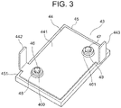
- FIG. 3 is a perspective view for illustrating the bus bar unit 43 of FIG. 2 .
- the holder 45 has a holder surface 451 orthogonal to a thickness direction of the holder 45.
- the holder 45 is arranged with the holder surface 451 facing the control board 42. Further, the holder 45 is made of a resin having an electrical insulating property.
- the bus bar 44 is arranged on the holder surface 451 of the holder 45. Further, the bus bar 44 includes a plate-like portion 441, a first terminal 442, and a second terminal 443. The plate-like portion 441 is placed on the holder surface 451 in an overlapping manner. The first terminal 442 and the second terminal 443 project from the plate-like portion 441 as a plurality of terminals.
- the bus bar 44 is made of a material having electroconductivity. In this example, the bus bar 44 is made of copper.
- the plate-like portion 441 is a band-shaped plate.
- the first terminal 442 and the second terminal 443 project from the plate-like portion 441 to a side opposite to the holder 45.
- the first terminal 442 projects from one end portion of both end portions of the plate-like portion 441 in a width direction of the plate-like portion 441, and the second terminal 443 projects from the other end portion of the end portions.
- Positions of the first terminal 442 and the second terminal 443 in a longitudinal direction of the plate-like portion 441 are different from each other.
- any ones of the connection terminals of the plurality of power modules 411 are selectively connected to the first terminal 442 and the second terminal 443, respectively.
- the holder 45 has a first protruding portion 46 and a second protruding portion 47 that project from the holder surface 451.
- the first protruding portion 46 and the second protruding portion 47 are formed at different positions on the holder surface 451.
- Each of the first protruding portion 46 and the second protruding portion 47 is made of a resin having an electrical insulating property.
- Each of lengths of the first terminal 442 and the second terminal 443 is larger than each of height dimensions of the first protruding portion 46 and the second protruding portion 47 from the holder surface 451.
- the plate-like portion 441 has a first through hole 400 and a second through hole 401.
- the first protruding portion 46 is press-fitted into the first through hole 400.
- the second protruding portion 47 is press-fitted into the second through hole 401.
- the bus bar 44 is held on the holder 45 by press-fitting the first protruding portion 46 into the first through hole 400 and press-fitting the second protruding portion 47 into the second through hole 401.
- Each of the first through hole 400 and the second through hole 401 has an axis extending along a thickness direction of the plate-like portion 441.
- a position of the first through hole 400 formed in the plate-like portion 441 is closer to the first terminal 442 than to a middle position of the plate-like portion 441 in the width direction. Further, the position of the first through hole 400 formed in the plate-like portion 441 matches a position of the first terminal 442 in the longitudinal direction of the plate-like portion 441. A distance from the first through hole 400 to the first terminal 442 is smaller than a distance from the first through hole 400 to the second terminal 443.
- a position of the second through hole 401 formed in the plate-like portion 441 is closer to the second terminal 443 than to a middle position of the plate-like portion 441 in the width direction. Further, the position of the second through hole 401 formed in the plate-like portion 441 matches a position of the second terminal 443 in the longitudinal direction of the plate-like portion 441. A distance from the second through hole 401 to the second terminal 443 is smaller than a distance from the second through hole 401 to the first terminal 442.
- a straight line that connects the first through hole 400 and the second through hole 401 is inclined with respect to the longitudinal direction of the plate-like portion 441.
- FIG. 4 is a perspective view for illustrating the first protruding portion 46 of FIG. 3 .
- the first protruding portion 46 has a first columnar portion 461 and a plurality of first ribs 462.
- the first columnar portion 461 projects from the holder surface 451.
- the plurality of first ribs 462 are formed on an outer peripheral surface of the first columnar portion 461.
- the first columnar portion 461 has a columnar shape. A center axis of the first columnar portion 461 is orthogonal to the holder surface 451. An outer diameter of the first columnar portion 461 is smaller than an inner diameter of the first through hole 400. A height dimension of the first columnar portion 461 from the holder surface 451 is larger than a thickness of the plate-like portion 441.
- the plurality of first ribs 462 are formed so as to be spaced apart from each other in a circumferential direction of the first columnar portion 461.
- the plurality of first ribs 462 are formed at equal intervals in the circumferential direction of the first columnar portion 461.
- four first ribs 462 are formed on the outer peripheral surface of the first columnar portion 461.
- Each of the first ribs 462 projects radially outward from the outer peripheral surface of the first columnar portion 461. Further, each of the first ribs 462 is formed along a height direction of the first columnar portion 461. Each of the first ribs 462 is formed to extend over the entire length in the height direction of the first columnar portion 461. First tapered surfaces 463, each being inclined in a direction of approaching the center axis of the first protruding portion 46 toward an end surface of the first protruding portion 46, are formed at an end portion of the first protruding portion 46.
- FIG. 5 is a perspective view for illustrating the second protruding portion 47 of FIG. 3 .
- the second protruding portion 47 has a second columnar portion 471 and a plurality of second ribs 472.
- the second columnar portion 471 projects from the holder surface 451.
- the plurality of second ribs 472 are formed on an outer peripheral surface of the second columnar portion 471.
- the second columnar portion 471 has a columnar shape. A center axis of the second columnar portion 471 is orthogonal to the holder surface 451. An outer diameter of the second columnar portion 471 is smaller than an inner diameter of the second through hole 401. A height dimension of the second columnar portion 471 from the holder surface 451 is larger than the thickness of the plate-like portion 441.
- the plurality of second ribs 472 are formed so as to be spaced apart from each other in a circumferential direction of the second columnar portion 471.
- the plurality of second ribs 472 are formed at equal intervals in the circumferential direction of the second columnar portion 471.
- the number of second ribs 472 formed on the outer peripheral surface of the second columnar portion 471 is smaller than the number of first ribs 462 formed on the outer peripheral surface of the first columnar portion 461.
- two second ribs 472 are formed on the outer peripheral surface of the second columnar portion 471.
- Each of the second ribs 472 projects radially outward from the outer peripheral surface of the second columnar portion 471. Further, each of the second ribs 472 is formed along a height direction of the second columnar portion 471. Each of the second ribs 472 is formed to extend over the entire length in the height direction of the second columnar portion 471. Second tapered surfaces 473, each being inclined in a direction of approaching the center axis of the second protruding portion 47 toward an end surface of the second protruding portion 47, are formed at an end portion of the second protruding portion 47.
- FIG. 6 is a perspective view for illustrating the first through hole 400 formed in the plate-like portion 441 of FIG. 3 .
- FIG. 7 is a sectional view taken along the line VII-VII of FIG. 6 .
- the plate-like portion 441 has an opposed surface 441a to be opposed to the holder surface 451.
- the first through hole 400 is defined by a first through hole forming portion 48 of the plate-like portion 441, which is formed in a cylindrical shape.
- an inner surface of the first through hole forming portion 48 serves as an inner surface of the first through hole 400.
- the first through hole forming portion 48 projects from the plate-like portion 441 to a side opposite to the opposed surface 441a.
- the first through hole 400 has a circular sectional shape.
- the first through hole forming portion 48 has a first cylindrical portion 481 and a first annular portion 482.
- the first annular portion 482 connects the first cylindrical portion 481 to the plate-like portion 441.
- the first cylindrical portion 481 has a circular cylindrical shape.
- the inner surface of the first through hole 400 includes a first hole cylindrical inner surface 481a and a first hole inclined inner surface 482a.
- the first hole cylindrical inner surface 481a corresponds to an inner surface of the first cylindrical portion 481.
- the first hole inclined inner surface 482a corresponds to an inner surface of the first annular portion 482.
- the first hole inclined inner surface 482a is inclined with respect to the opposed surface 441a. Further, the first hole inclined inner surface 482a is inclined in a direction of reducing an inner diameter of the first through hole 400 from the opposed surface 441a toward an end portion of the first through hole forming portion 48.
- the first hole cylindrical inner surface 481a extends from the first hole inclined inner surface 482a to the end portion of the first through hole forming portion 48 with the inner diameter of the first through hole 400 kept constant.
- the first hole inclined inner surface 482a is a curved surface that protrudes to an inner side of the first through hole 400.
- the first hole inclined inner surface 482a is seen as a curved line that is inclined with respect to the opposed surface 441a in a cross section of the first through hole forming portion 48, which is taken along a plane containing an axis of the first through hole 400.
- the first hole inclined inner surface 482a is smoothly continuous with the opposed surface 441a and the first hole cylindrical inner surface 481a.
- the first hole cylindrical inner surface 481a is a circular cylindrical surface. Further, a dimension of the first hole cylindrical inner surface 481a in an axial direction of the first through hole 400 is larger than the thickness of the plate-like portion 441.
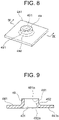
- FIG. 8 is a perspective view for illustrating the second through hole 401 formed in the plate-like portion 441 of FIG. 3 .
- FIG. 9 is a sectional view taken along the line IX-IX of FIG. 8 .
- the second through hole 401 is defined by a second through hole forming portion 49 of the plate-like portion 441, which is formed in a cylindrical shape.
- an inner surface of the second through hole forming portion 49 serves as an inner surface of the second through hole 401.
- the second through hole forming portion 49 projects from the plate-like portion 441 to a side opposite to the opposed surface 441a.
- the second through hole 401 has a circular sectional shape.
- the second through hole forming portion 49 has a second cylindrical portion 491 and a second annular portion 492.
- the second annular portion 492 connects the second cylindrical portion 491 to the plate-like portion 441.
- the second cylindrical portion 491 has a circular cylindrical shape.
- the inner surface of the second through hole 401 includes a second hole cylindrical inner surface 491a and a second hole inclined inner surface 492a.
- the second hole cylindrical inner surface 491a corresponds to an inner surface of the second cylindrical portion 491.
- the second hole inclined inner surface 492a corresponds to an inner surface of the second annular portion 492.
- the second hole inclined inner surface 492a is inclined with respect to the opposed surface 441a. Further, the second hole inclined inner surface 492a is inclined in a direction of reducing an inner diameter of the second through hole 401 from the opposed surface 441a toward an end portion of the second through hole forming portion 49.
- the second hole cylindrical inner surface 491a extends from the second hole inclined inner surface 492a to the end portion of the second through hole forming portion 49 with the inner diameter of the second through hole 401 kept constant.
- the second hole inclined inner surface 492a is a curved surface that protrudes to an inner side of the second through hole 401.
- the second hole inclined inner surface 492a is seen as a curved line that is inclined with respect to the opposed surface 441a in a cross section of the second through hole forming portion 49, which is taken along a plane containing an axis of the second through hole 401.
- the second hole inclined inner surface 492a is smoothly continuous with the opposed surface 441a and the second hole cylindrical inner surface 491a.
- the second hole cylindrical inner surface 491a is a circular cylindrical surface. Further, a dimension of the second hole cylindrical inner surface 491a in an axial direction of the second through hole 401 is larger than the thickness of the plate-like portion 441.
- FIG. 10 is a perspective view for illustrating a state in which the first protruding portion 46 of FIG. 4 is press-fitted into the first through hole 400 of the plate-like portion 441.
- FIG. 11 is a sectional view taken along the line XI-XI of FIG. 10 .
- the plate-like portion 441 is placed on the holder surface 451 in an overlapping manner with the opposed surface 441a opposed to the holder surface 451.
- the first protruding portion 46 is press-fitted into the first through hole 400 under a state in which the first ribs 462 are in contact with the first hole cylindrical inner surface 481a. As a result, the first protruding portion 46 is tightened by the first hole cylindrical inner surface 481a.
- Gaps are defined between the outer peripheral surface of the first columnar portion 461 and the first hole cylindrical inner surface 481a under a state in which the first protruding portion 46 is press-fitted into the first through hole 400.
- Each of the gaps defined between the outer peripheral surface of the first columnar portion 461 and the first hole cylindrical inner surface 481a has such a dimension as to inhibit passage of foreign matter having a size larger than a reference size allowed to enter the control unit 4.
- the end portion of the first protruding portion 46 projects beyond the first through hole forming portion 48 under a state in which the first protruding portion 46 is press-fitted into the first through hole 400.
- the first protruding portion 46 is press-fitted into the first through hole 400 from the opposed surface 441a side of the plate-like portion 441.
- a first space portion 405 in which the plurality of first ribs 462 are exposed is defined between the first hole inclined inner surface 482a and the holder 45.
- the first space portion 405 is defined between the first hole inclined inner surface 482a and the holder 45 around the entire circumference of the first protruding portion 46.
- the first ribs 462 but also the outer peripheral surface of the first columnar portion 461 is exposed in the first space portion 405.
- FIG. 12 is a sectional view for illustrating a state in which the second protruding portion 47 of FIG. 5 is press-fitted into the second through hole 401 of the plate-like portion 441.
- the second protruding portion 47 is press-fitted into the second through hole 401 under a state in which the second ribs 472 are in contact with the second hole cylindrical inner surface 491a.
- the second protruding portion 47 is tightened by the second hole cylindrical inner surface 491a.
- Gaps are defined between the outer peripheral surface of the second columnar portion 471 and the second hole cylindrical inner surface 491a under a state in which the second protruding portion 47 is press-fitted into the second through hole 401.
- Each of the gaps defined between the outer peripheral surface of the second columnar portion 471 and the second hole cylindrical inner surface 491a has such a dimension as to inhibit passage of foreign matter having a size larger than a set allowable size allowed to enter the control unit 4.
- the end portion of the second protruding portion 47 projects beyond the second through hole forming portion 49 under a state in which the second protruding portion 47 is press-fitted into the second through hole 401.
- the second protruding portion 47 is press-fitted into the second through hole 401 from the opposed surface 441a side of the plate-like portion 441.
- a second space portion 406 in which the plurality of second ribs 472 are exposed is defined between the second hole inclined inner surface 492a and the holder 45.
- the second space portion 406 is defined between the second hole inclined inner surface 492a and the holder 45 around the entire circumference of the second protruding portion 47.
- the second ribs 472 but also the outer peripheral surface of the second columnar portion 471 is exposed in the second space portion 406.
- the inner surface of the first through hole 400 includes the first hole inclined inner surface 482a and the first hole cylindrical inner surface 481a. Further, the first protruding portion 46 is press-fitted into the first through hole 400 under a state in which the plurality of first ribs 462 are in contact with the first hole cylindrical inner surface 481a. Thus, when the first protruding portion 46 is press-fitted into the first through hole 400, the first protruding portion 46 can easily be guided to the first hole cylindrical inner surface 481a along the first hole inclined inner surface 482a. As a result, the first protruding portion 46 can easily be press-fitted into the first through hole 400. Thus, the plate-like portion 441 can easily be positioned with respect to the holder 45.
- the first through hole forming portion 48 projecting from the plate-like portion 441, the dimension of the first hole cylindrical inner surface 481a in the thickness direction of the plate-like portion 441 can be ensured.
- a contact area of each of the first ribs 462 with the first hole cylindrical inner surface 481a can easily be ensured, and the first protruding portion 46 can be prevented from easily being disengaged from the first through hole 400.
- the first protruding portion 46 is not required to be welded to the plate-like portion 441. As a result, a burden of welding work can be eliminated.
- the first hole inclined inner surface 482a is located between the first hole cylindrical inner surface 481a and the opposed surface 441a.
- an inner diameter of an opening portion of the first through hole 400 formed in the opposed surface 441a can be set larger than an inner diameter of the first hole cylindrical inner surface 481a.
- the first ribs 462 can be made less liable to be scraped at a boundary between the first hole cylindrical inner surface 481a and the first hole inclined inner surface 482a.
- generation of shavings of the first protruding portion 46 as foreign matter can be suppressed.
- generation of foreign matter at the time of manufacture of the electric driving device 1 and the electric power steering device 100 can be suppressed.
- the foreign matter When foreign matter is generated at the time of press-fitting of the first protruding portion 46 into the first through hole 400, the foreign matter may intrude into a space between the plate-like portion 441 and the holder surface 451. As a result, insertion of the first protruding portion 46 into the first through hole 400 may be incomplete, and the bus bar 44 is more liable to be disengaged from the holder 45. Further, the positioning accuracy of the bus bar 44 with respect to the holder 45 may decrease.
- the generation of foreign matter at the time of manufacture of the electric driving device 1 and the electric power steering device 100 can be suppressed.
- the bus bar 44 can be more reliably held on the holder 45, and decrease in the positioning accuracy of the bus bar 44 with respect to the holder 45 can be suppressed.
- the first space portion 405 in which the plurality of first ribs 462 are exposed is defined between the first hole inclined inner surface 482a and the holder 45.
- the first ribs 462 are scraped to generate foreign matter at the time of press-fitting of the first protruding portion 46 into the first through hole 400, the foreign matter can be received in the first space portion 405.
- the intrusion of foreign matter into the space between the plate-like portion 441 and the holder surface 451 can be more reliably prevented.
- the bus bar 44 can be more reliably held on the holder 45, and decrease in the positioning accuracy of the bus bar 44 with respect to the holder 45 can be more reliably suppressed.
- the dimension of the first hole cylindrical inner surface 481a in the axial direction of the first through hole 400 is larger than the thickness of the plate-like portion 441.
- increase in contact area of each of the first ribs 462 with the first hole cylindrical inner surface 481a can be more reliably achieved.
- disengagement of the first protruding portion 46 from the first through hole 400 can be more reliably prevented, and a state in which the bus bar 44 is held on the holder 45 can be more reliably maintained.
- the bus bar 44 has the first terminal 442 projecting from the plate-like portion 441 to the side opposite to the holder 45.
- the welding tool may interfere with the first terminal 442.
- a space in which the welding tool is arranged is required to be secured around the first protruding portion 46 and the first through hole 400.
- a position of the first through hole 400 is required to be separated from the first terminal 442 to a position at which the first terminal 442 does not interfere with the welding tool.
- the bus bar unit 43 is disadvantageously increased in size.
- the need of use of the welding tool configured to weld the first protruding portion 46 to the plate-like portion 441 is eliminated.
- the first through hole 400 can be formed at a position closer to the first terminal 442.
- increase in size of the bus bar unit 43 can be suppressed.
- the second through hole 401 can also be formed at a position closer to the second terminal 443. As a result, the suppression of increase in size of the bus bar unit 43 can be more reliably achieved.
- the inner surface of the second through hole 401 includes the second hole inclined inner surface 492a and the second hole cylindrical inner surface 491a. Still further, the second protruding portion 47 is press-fitted into the second through hole 401 under a state in which the plurality of second ribs 472 are in contact with the second hole cylindrical inner surface 491a. Thus, the second protruding portion 47 can easily be press-fitted into the second through hole 401. Further, when the second protruding portion 47 is press-fitted into the second through hole 401, generation of shavings of the second protruding portion 47 as foreign matter can be suppressed. Thus, the generation of foreign matter at the time of manufacture of the electric driving device 1 and the electric power steering device 100 can be suppressed.
- the plate-like portion 441 can be retained on the holder 45 at the positions of the first protruding portion 46 and the second protruding portion 47. As a result, a state in which the bus bar 44 is held on the holder 45 can be more reliably maintained.
- the number of second ribs 472 of the second protruding portion 47 is smaller than the number of first ribs 462 of the first protruding portion 46.
- the second protruding portion 47 can more easily be press-fitted into the second through hole 401.
- the second protruding portion 47 can be more reliably press-fitted into the second through hole 401. In this manner, inclination of the plate-like portion 441 with respect to the holder surface 451 can be suppressed.
- the first protruding portion 46 has four first ribs 462.
- the second protruding portion 47 has two second ribs 472.
- the plate-like portion 441 can be more precisely positioned with respect to the holder 45.
- the position of the second protruding portion 47 is misaligned with respect to the position of the second through hole 401 at the time of press-fitting of the first protruding portion 46 into the first through hole 400, the second protruding portion 47 can be press-fitted into the second through hole 401.
- the inclination of the plate-like portion 441 with respect to the holder surface 451 can be suppressed.
- the straight line that connects the first through hole 400 and the second through hole 401 is inclined with respect to the longitudinal direction of the plate-like portion 441.
- a distance between the first through hole 400 and the second through hole 401 can be increased.
- the bus bar 44 can be more stably held on the holder 45, and the positioning accuracy of the bus bar 44 with respect to the holder 45 can be improved.
- the first protruding portion 46 has four first ribs 462.
- the first protruding portion 46 may have two, three, or five or more first ribs 462.
- the second protruding portion 47 has two second ribs 472.
- the second protruding portion 47 may have three or more second ribs 472.
- two protruding portions that is, the first protruding portion 46 and the second protruding portion 47 are formed on the holder 45.
- three or more protruding portions may be formed on the holder 45 by forming one or more additional protruding portions, which are different from the first protruding portion 46 and the second protruding portion 47.
- the plate-like portion 441 has one or more additional through holes corresponding to the additional protruding portions.
- the plate-like portion 441 has three or more through holes.
- the additional protruding portion is press-fitted into the additional through hole.
- the additional protruding portion has the same configuration as the first protruding portion 46 except for the number of ribs.
- the additional protruding portion has a smaller number of ribs than the number of first ribs 462.
- the additional through hole has the same configuration as the first through hole 400.
- the straight line that connects the first through hole 400 and the second through hole 401 is inclined with respect to the longitudinal direction of the plate-like portion 441.
- the positions of the first through hole 400 and the second through hole 401 in the plate-like portion 441 are not limited to the above-mentioned positions.
- the first through hole 400 and the second through hole 401 may be located on a straight line extending along the longitudinal direction of the plate-like portion 441. Even in this manner, the bus bar 44 can be held on the holder 45.
- positions of the first through hole 400 and the second through hole 401 may be set regardless of the positions of the first terminal 442 and the second terminal 443.
- FIG. 13 is a perspective view for illustrating a first protruding portion 46 of an electric driving device 1 according to a second embodiment of this invention.
- a first recessed portion 452 that surrounds the first protruding portion 46 is formed in a holder surface 451 of a holder 45.
- the first recessed portion 452 is formed in the holder surface 451 around the entire circumference of the first protruding portion 46.
- FIG. 14 is a perspective view for illustrating a second protruding portion 47 of the electric driving device 1 according to the second embodiment of this invention.
- a second recessed portion 453 that surrounds the second protruding portion 47 is formed in the holder surface 451 of the holder 45.
- the second recessed portion 453 is formed in the holder surface 451 around the entire circumference of the second protruding portion 47.
- FIG. 15 is a perspective view for illustrating a state in which the first protruding portion 46 of FIG. 13 is press-fitted into a first through hole 400 of a plate-like portion 441.
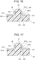
- FIG. 16 is a sectional view taken along the line XVI-XVI of FIG. 15 .
- a first space portion 405 in which a plurality of first ribs 462 are exposed is defined between an inner surface of the first recessed portion 452 and a first hole inclined inner surface 482a under a state in which the first protruding portion 46 is press-fitted into the first through hole 400.
- the first space portion 405 is defined between the first hole inclined inner surface 482a and the holder 45 around the entire circumference of the first protruding portion 46.
- FIG. 17 is a perspective view for illustrating a state in which the second protruding portion 47 of FIG. 14 is press-fitted into a second through hole 401.
- a second space portion 406 in which a plurality of second ribs 472 are exposed is defined between an inner surface of the second recessed portion 453 and a second hole inclined inner surface 492a under a state in which the second protruding portion 47 is press-fitted into the second through hole 401.
- the second space portion 406 is defined between the second hole inclined inner surface 492a and the holder 45 around the entire circumference of the second protruding portion 47.
- Other configurations are the same as those of the first embodiment.
- the first recessed portion 452 that surrounds the first protruding portion 46 is formed in the holder surface 451.
- the first space portion 405 can be more reliably defined between the inner surface of the first recessed portion 452 and the first hole inclined inner surface 482a.
- a capacity of the first space portion 405 can be increased as compared to that of the first space portion 405 in the first embodiment.
- the foreign matter can be received in the first space portion 405.
- a bus bar 44 can be more reliably held on the holder 45, and the positioning accuracy of the bus bar 44 with respect to the holder 45 can be improved.
- the capacity of the first space portion 405 can be ensured with the first recessed portion 452. As a result, further improvement of the productivity of the bus bar units 43 can be achieved.
- the second recessed portion 453 that surrounds the second protruding portion 47 is also formed in the holder surface 451.
- a capacity of the second space portion 406 can also be increased as compared to that of the second space portion 406 in the first embodiment.
- the bus bar 44 can be more reliably held on the holder 45, and the positioning accuracy of the bus bar 44 with respect to the holder 45 can be improved.
- a further reduction in size of the bus bar unit 43 and further improvement of productivity of the bus bar unit 43 can be achieved.
- the first hole inclined inner surface 482a is seen as a curved line that is inclined with respect to the opposed surface 441a when taken along a plane containing an axis of the first through hole 400.
- the first hole inclined inner surface 482a may be formed to be seen as a straight line that is inclined with respect to the opposed surface 441a when taken along the plane containing the axis of the first through hole 400.
- the second hole inclined inner surface 492a is seen as a curved line that is inclined with respect to the opposed surface 441a when taken along a plane containing an axis of the second through hole 401.
- the second hole inclined inner surface 492a may be formed to be seen as a straight line that is inclined with respect to the opposed surface 441a when taken along the plane containing the axis of the second through hole 401.
- FIG. 18 is a perspective view for illustrating a first protruding portion 46 of an electric driving device 1 according to a third embodiment of this invention.
- FIG. 19 is a perspective view for illustrating a second protruding portion 47 of the electric driving device 1 according to the third embodiment of this invention.
- a holder surface 451 of a holder 45 includes a base surface 454, a first holder inclined surface 455, and a second holder inclined surface 456.
- the base surface 454 is a flat surface.
- the first holder inclined surface 455 is formed around the first protruding portion 46.
- the first holder inclined surface 455 is formed around the entire circumference of the first protruding portion 46 between the base surface 454 and the first protruding portion 46. Further, the first holder inclined surface 455 is inclined in a direction of approaching an end portion of the first protruding portion 46 with respect to the base surface 454 from the base surface 454 toward the first protruding portion 46.
- the first holder inclined surface 455 has a plurality of first recessed portions 457 that are formed in such a manner as to match positions of a plurality of first ribs 462 in a circumferential direction of the first columnar portion 461, respectively.
- the first holder inclined surface 455 has four first recessed portions 457.
- the first ribs 462 are exposed inside the first recessed portions 457, respectively.
- a width dimension of each of the first recessed portions 457 in a circumferential direction of the first protruding portion 46 matches a width dimension of each of the first ribs 462 in the circumferential direction of the first protruding portion 46.
- the second holder inclined surface 456 is formed around the second protruding portion 47.
- the second holder inclined surface 456 is formed around the entire circumference of the second protruding portion 47 between the base surface 454 and the second protruding portion 47. Further, the second holder inclined surface 456 is inclined in a direction of approaching an end portion of the second protruding portion 47 with respect to the base surface 454 from the base surface 454 toward the second protruding portion 47.
- the second holder inclined surface 456 has a plurality of second recessed portions 458 that are formed in such a manner as to match positions of a plurality of second ribs 472 in a circumferential direction of the second columnar portion 471, respectively.
- the second holder inclined surface 456 has two second recessed portions 458.
- the second ribs 472 are exposed inside the second recessed portions 458, respectively.
- a width dimension of each of the second recessed portions 458 in a circumferential direction of the second protruding portion 47 matches a width dimension of each of the second ribs 472 in the circumferential direction of the second protruding portion 47.
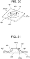
- FIG. 20 is a perspective view for illustrating a first through hole 400 of the electric driving device 1 according to the third embodiment of this invention.
- FIG. 21 is a sectional view taken along the line XXI-XXI of FIG. 20 .
- a first hole inclined inner surface 482a is seen as a straight line that is inclined with respect to an opposed surface 441a in a cross section of a first through hole forming portion 48, which is taken along a plane containing an axis of the first through hole 400.
- Other configurations of the first through hole 400 are the same as those of the first through hole 400 in the first embodiment.
- FIG. 22 is a perspective view for illustrating a second through hole 401 of the electric driving device 1 according to the third embodiment of this invention.
- FIG. 23 is a sectional view taken along the line XXIII-XXIII of FIG. 22 .
- a second hole inclined inner surface 492a is seen as a straight line that is inclined with respect to the opposed surface 441a in a cross section of a second through hole forming portion 49, which is taken along a plane containing an axis of the second through hole 401.
- Other configurations of the second through hole 401 are the same as those of the second through hole 401 in the first embodiment.
- FIG. 24 is a perspective view for illustrating a state in which the first protruding portion 46 of FIG. 18 is press-fitted into a first through hole 400 of a plate-like portion 441.
- FIG. 25 is a sectional view taken along the line XXV-XXV of FIG. 24 .
- a plurality of first space portions 405 are individually defined between inner surfaces of the plurality of first recessed portions 457 and the first hole inclined inner surface 482a under a state in which the first protruding portion 46 is press-fitted into the first through hole 400.
- positions of the first space portions 405 in the circumferential direction of the first protruding portion 46 match positions of the first ribs 462 in the circumferential direction of the first protruding portion 46, respectively.
- Each of the first ribs 462 is exposed inside a corresponding one of the first space portions 405.
- the first holder inclined surface 455 is formed to extend along the first hole inclined inner surface 482a.
- the first holder inclined surface 455 is seen as a straight line that is inclined with respect to the base surface 454 in a cross section of the holder surface 451, which is taken along a plane containing an axis of the first protruding portion 46.
- the first holder inclined surface 455 is in contact with the first hole inclined inner surface 482a except for the first recessed portions 457. This arrangement prevents exposure of an outer peripheral surface of the first columnar portion 461 in the first space portions 405.
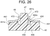
- FIG. 26 is a perspective view for illustrating a state in which the second protruding portion 47 of FIG. 19 is press-fitted into a first through hole 400 of the plate-like portion 441.
- a plurality of second space portions 406 are individually defined between inner surfaces of the plurality of second recessed portions 458 and the second hole inclined inner surface 492a under a state in which the second protruding portion 47 is press-fitted into the second through hole 401.
- positions of the second space portions 406 in the circumferential direction of the second protruding portion 47 match positions of the second ribs 472 in the circumferential direction of the second protruding portion 47, respectively.
- Each of the second ribs 472 is exposed inside a corresponding one of the second space portions 406.
- the second holder inclined surface 456 is formed to extend along the second hole inclined inner surface 492a.
- the second holder inclined surface 456 is seen as a straight line that is inclined with respect to the base surface 454 in a cross section of the holder surface 451, which is taken along a plane containing an axis of the second protruding portion 47.
- the second holder inclined surface 456 is in contact with the second hole inclined inner surface 492a except for the second recessed portions 458. This arrangement prevents exposure of an outer peripheral surface of the second columnar portion 471 in the second space portions 406.
- Other configurations are the same as those of the first embodiment.
- the plurality of first recessed portions 457 are formed in such a manner as to match the positions of the plurality of first ribs 462 in the circumferential direction of the first columnar portion 461, respectively.
- the holder surface 451 includes the first holder inclined surface 455 formed to extend along the first hole inclined inner surface 482a.
- the plurality of first space portions 405 in which the plurality of first ribs 462 are individually exposed can be defined between the inner surfaces of the first recessed portions 457 and the first holder inclined surface 455.
- the contact of the first hole inclined inner surface 482a with the first holder inclined surface 455 can prevent exposure of the outer peripheral surface of the first columnar portion 461 in the first space portions 405. In this manner, movement of foreign matter into gaps between the outer peripheral surface of the first columnar portion 461 and the first hole cylindrical inner surface 481a can be prevented. As a result, a state in which foreign matter is confined in the first space portions 405 can be more reliably maintained. Thus, intrusion of foreign matter into the control unit 4 can be more reliably prevented.
- the plurality of second recessed portions 458 are formed in such a manner as to match the positions of the plurality of second ribs 472 in the circumferential direction of the second columnar portion 471, respectively.
- the holder surface 451 includes the second holder inclined surface 456 that is formed to extend along the second hole inclined inner surface 492a.
- the first holder inclined surface 455 that is formed to extend along the first hole inclined inner surface 482a and the second holder inclined surface 456 that is formed to extend along the second hole inclined inner surface 492a may be applied to the holder surface 451 according to the second embodiment.
- 1 electric driving device 3 motor, 4 control unit, 43 bus bar unit, 44 bus bar, 45 holder, 46 first protruding portion, 47 second protruding portion, 48 first through hole forming portion, 49 second through hole forming portion, 400 first through hole, 401 second through hole, 405 first space portion, 441 plate-like portion, 441a opposed surface, 442 first terminal, 443 second terminal, 451 holder surface, 452,457 first recessed portion, 455 first holder inclined surface, 461 first columnar portion, 462 first rib, 471 second columnar portion, 472 second rib, 481a first hole cylindrical inner surface, 482a first hole inclined inner surface, 491a second hole cylindrical inner surface, 492a second hole inclined inner surface
Landscapes
- Engineering & Computer Science (AREA)
- Power Engineering (AREA)
- Chemical & Material Sciences (AREA)
- Combustion & Propulsion (AREA)
- Transportation (AREA)
- Mechanical Engineering (AREA)
- Microelectronics & Electronic Packaging (AREA)
- Power Steering Mechanism (AREA)
- Motor Or Generator Frames (AREA)
- Insulation, Fastening Of Motor, Generator Windings (AREA)
Abstract
Description
- This invention relates to an electric driving device including a motor and a control unit, and to an electric power steering device.
- Hitherto, there has been known an electric power steering device including a bus bar held on a holder. The holder is provided inside a control unit, and has protruding portions made of a resin. The bus bar has through holes. When the protruding portions are press-fitted into the through holes, the bus bar is held on the holder. Each of the protruding portions has a columnar portion and a plurality of ribs formed on an outer peripheral surface of the columnar portion. The plurality of ribs are in contact with an inner surface of the through hole of the bus bar. Further, end portions of the protruding portions are welded to the bus bar through heating (see, for example, Patent Literature 1).
- [PTL 1]
JP 2018-61423 A - In the case of the related-art electric power steering device disclosed in
Patent Literature 1, the end portions of the protruding portions are required to be heated so as to be welded to the bus bar. Thus, time and effort are needed to manufacture the electric power steering device. - Further, in the case of the related-art electric power steering device, when the protruding portions are press-fitted into the through holes, the ribs are liable to be scraped by an edge of an opening portion of the through hole. As a result, shavings are more liable to be generated from the ribs as foreign matter.
- This invention has been made to solve the problems described above, and has an object to provide an electric driving device and an electric power steering device that are easily manufactured and enable suppression of generation of foreign matter at the time of manufacture.
- According to this invention, an electric driving device and an electric power steering device includes: a motor; and a control unit configured to control the motor, wherein the control unit includes: a holder having a holder surface; and a bus bar arranged on the holder surface, wherein the bus bar has a plate-like portion placed on the holder surface in an overlapping manner, wherein the plate-like portion has an opposed surface opposed to the holder surface, wherein the holder has a first protruding portion protruding from the holder surface, wherein the first protruding portion has a first columnar portion and a plurality of first ribs formed on an outer peripheral surface of the first columnar portion so as to be spaced apart from each other in a circumferential direction of the first columnar portion, wherein the plate-like portion has a first through hole into which the first protruding portion is press-fitted, wherein the first through hole is defined by a first through hole forming portion formed in a cylindrical shape so as to project from the plate-like portion to a side opposite to the opposed surface, wherein the first through hole has an inner surface including: a first hole inclined inner surface that is inclined in a direction of reducing an inner diameter of the first through hole with respect to the opposed surface from the opposed surface toward an end portion of the first through hole forming portion; and a first hole cylindrical inner surface extending from the first hole inclined inner surface to the end portion of the first through hole forming portion with the inner diameter of the first through hole kept constant, and wherein the first protruding portion is press-fitted into the first through hole under a state in which the plurality of first ribs are in contact with the first hole cylindrical inner surface.
- The electric driving device and the electric power steering device according to this invention are easily manufactured, and enable suppression of generation of foreign matter at the time of manufacture.
-
-
FIG. 1 is a configuration diagram for illustrating an electric power steering device according to a first embodiment of this invention. -
FIG. 2 is a sectional view for illustrating an electric driving device ofFIG. 1 . -
FIG. 3 is a perspective view for illustrating a bus bar unit ofFIG. 2 . -
FIG. 4 is a perspective view for illustrating a first protruding portion ofFIG. 3 . -
FIG. 5 is a perspective view for illustrating a second protruding portion ofFIG. 3 . -
FIG. 6 is a perspective view for illustrating a first through hole formed in a plate-like portion ofFIG. 3 . -
FIG. 7 is a sectional view taken along the line VII-VII ofFIG. 6 . -
FIG. 8 is a perspective view for illustrating a second through hole formed in the plate-like portion ofFIG. 3 . -
FIG. 9 is a sectional view taken along the line IX-IX ofFIG. 8 . -
FIG. 10 is a perspective view for illustrating a state in which the first protruding portion ofFIG. 4 is press-fitted into the first through hole of the plate-like portion. -
FIG. 11 is a sectional view taken along the line XI-XI ofFIG. 10 . -
FIG. 12 is a sectional view for illustrating a state in which the second protruding portion ofFIG. 5 is press-fitted into the second through hole of the plate-like portion. -
FIG. 13 is a perspective view for illustrating a first protruding portion of an electric driving device according to a second embodiment of this invention. -
FIG. 14 is a perspective view for illustrating a second protruding portion of the electric driving device according to the second embodiment of this invention. -
FIG. 15 is a perspective view for illustrating a state in which the first protruding portion ofFIG. 13 is press-fitted into a first through hole of a plate-like portion. -
FIG. 16 is a sectional view taken along the line XVI-XVI ofFIG. 15 . -
FIG. 17 is a sectional view for illustrating a state in which the second protruding portion ofFIG. 14 is press-fitted into a second through hole. -
FIG. 18 is a perspective view for illustrating a first protruding portion of an electric driving device according to a third embodiment of this invention. -
FIG. 19 is a perspective view for illustrating a second protruding portion of the electric driving device according to the third embodiment of this invention. -
FIG. 20 is a perspective view for illustrating a first through hole of the electric driving device according to the third embodiment of this invention. -
FIG. 21 is a sectional view taken along the line XXI-XXI ofFIG. 20 . -
FIG. 22 is a perspective view for illustrating a second through hole of the electric driving device according to the third embodiment of this invention. -
FIG. 23 is a sectional view taken along the line XXIII-XXIII ofFIG. 22 . -
FIG. 24 is a perspective view for illustrating a state in which the first protruding portion ofFIG. 18 is press-fitted into the first through hole of a plate-like portion. -
FIG. 25 is a sectional view taken along the line XXV-XXV ofFIG. 24 . -
FIG. 26 is a sectional view for illustrating a state in which the second protruding portion ofFIG. 19 is press-fitted into the first through hole of the plate-like portion. - Now, embodiments of this invention are described with reference to the drawings.
-
FIG. 1 is a configuration diagram for illustrating an electric power steering device according to a first embodiment of this invention. An electricpower steering device 100 according to this embodiment is, for example, a vehicle electric power steering device to be mounted in, for example, an automobile. The electricpower steering device 100 includes a pair oftie rods 101, a rackshaft mechanism unit 102, asteering wheel 103, asteering shaft 104, aspeed reducer 105, and anelectric driving device 1. - The pair of
tie rods 101 are individually coupled to a pair of steeredwheels 106. The rackshaft mechanism unit 102 is arranged between the pair oftie rods 101. The rackshaft mechanism unit 102 includes a housing having a cylindrical shape and a rack shaft housed inside the housing. The rack shaft of the rackshaft mechanism unit 102 is coupled to each of the pair oftie rods 101. - The
steering wheel 103 is coupled to the rackshaft mechanism unit 102 through intermediation of thesteering shaft 104. When a driver steers thesteering wheel 103, torque generated through steering is transmitted to the rack shaft of the rackshaft mechanism unit 102 via thesteering shaft 104. Further, theelectric driving device 1 is provided to the rackshaft mechanism unit 102 through intermediation of thespeed reducer 105. - The
electric driving device 1 is a torque generating device configured to generate an assist torque. The assist torque generated by theelectric driving device 1 is increased by thespeed reducer 105 and thereafter transmitted to the rack shaft of the rackshaft mechanism unit 102. The rack shaft of the rackshaft mechanism unit 102 is moved in directions indicated by an arrow A ofFIG. 1 with the torque generated through the steering of thesteering wheel 103 and the assist torque generated by theelectric driving device 1. As a result, a driver's steering force is assisted by the assist torque generated by theelectric driving device 1. - When the rack shaft is moved in the directions indicated by the arrow A, the pair of
tie rods 101 are moved to steer the steeredwheels 106 to thereby cause a vehicle to turn. As a result of assistance with the torque generated by theelectric driving device 1 for the steering force, the driver can turn the vehicle with a smaller steering force. - A
torque sensor 110 configured to detect the torque generated through the steering of thesteering wheel 103 is provided to thesteering shaft 104. Information of the torque detected by thetorque sensor 110 is transmitted as an electric signal from thetorque sensor 110 to theelectric driving device 1. Further,vehicle information 111 including speed information of the vehicle is transmitted as an electric signal from a vehicle sensor installed in the vehicle to theelectric driving device 1. Further, avehicle power supply 112 installed in the vehicle is connected to theelectric driving device 1. Examples of thevehicle power supply 112 include a battery and an alternator. -
FIG. 2 is a sectional view for illustrating theelectric driving device 1 ofFIG. 1 . Theelectric driving device 1 includes ahousing 2, amotor 3, acontrol unit 4, and aframe 5. - The
housing 2 includes acase 21 made of a metal and acover 22 made of a resin. Thecover 22 is mounted to thecase 21. - The
case 21 includes acylindrical portion 211 and anend wall portion 212. Thecylindrical portion 211 has an axis. Theend wall portion 212 closes one end portion of thecylindrical portion 211 in an axial direction. The axis of thecylindrical portion 211 matches an axis of thecase 21. Thecase 21 has an opening portion formed at the other end portion of thecylindrical portion 211 in the axial direction. Thecover 22 closes the opening portion of thecase 21. - The
motor 3, thecontrol unit 4, and theframe 5 are housed in thehousing 2. In this manner, theelectric driving device 1 is formed as an integrated electric driving device in which themotor 3 and thecontrol unit 4 are integrated with each other. - The
motor 3 is housed in thecase 21. Thecontrol unit 4 is arranged between themotor 3 and thecover 22. Theframe 5 is arranged between themotor 3 and thecontrol unit 4. - The
frame 5 is made of a metal. Theframe 5 has such a shape as to be fitted into an inner surface of thecylindrical portion 211. Theframe 5 is mounted to thecase 21 in a state of being in contact with the inner surface of thecylindrical portion 211. As a result, theframe 5 is electrically and thermally connected to thecase 21. - The
motor 3 includes anoutput shaft 31, arotor 32, astator 33, and awire connection member 34. Theoutput shaft 31 is arranged coaxially with thecase 21. Therotor 32 is fixed to theoutput shaft 31. Thestator 33 having a cylindrical shape surrounds an outer peripheral portion of therotor 32. Thewire connection member 34 having an annular shape is provided to thestator 33. - The
output shaft 31 has a first end portion and a second end portion. A through hole is formed in a center of theend wall portion 212. The first end portion of theoutput shaft 31 is caused to pass through the through hole formed in theend wall portion 212 as an output portion of theelectric driving device 1. A recess is formed in a center of theframe 5. The second end portion of theoutput shaft 31 is placed in the recess formed in theframe 5. - The
output shaft 31 is rotatably supported by thecase 21 and theframe 5 through intermediation of twobearings 20 that are individually mounted to theend wall portion 212 and theframe 5. Thebearing 20, which is mounted to theend wall portion 212, is fitted into the through hole formed in theend wall portion 212. - The
rotor 32 includes a rotor core and a plurality of permanent magnets. The rotor core is fixed to theoutput shaft 31. The plurality of permanent magnets are provided to the rotor core. Therotor 32 is rotated integrally with theoutput shaft 31 about an axis of theoutput shaft 31. - The
stator 33 is fixed to the inner surface of thecylindrical portion 211. Further, thestator 33 is arranged coaxially with theoutput shaft 31. Still further, thestator 33 includes a stator core having a cylindrical shape and a three-phase stator winding provided to the stator core. - The
wire connection member 34 is arranged between thestator 33 and theframe 5. The three-phase stator winding includes a plurality of winding portions. End portions of the plurality of winding portions are electrically connected to each other through thewire connection member 34. The plurality of winding portions are connected in a star connection or delta connection state through thewire connection member 34. This wire connection forms the three-phase stator winding. In this example, themotor 3 is formed as a three-phase brushless motor. - A
sensor magnet 35 is fixed to the second end portion of theoutput shaft 31. Thesensor magnet 35 rotates integrally with theoutput shaft 31. Arotation sensor 36 is provided in the recess formed in theframe 5. Therotation sensor 36 is opposed to thesensor magnet 35 in an axial direction of theoutput shaft 31. Therotation sensor 36 is configured to detect a magnetic field of thesensor magnet 35, which changes in accordance with the rotation of theoutput shaft 31. In this manner, therotation sensor 36 generates rotation information in accordance with the rotation of theoutput shaft 31 as an electric signal. - A
connector 10 is provided on an outer surface of thecover 22. Theconnector 10 includes a power connector portion and a signal connector portion. Thevehicle power supply 112 is electrically connected to the power connector portion. Thetorque sensor 110 and the vehicle sensor are electrically connected to the signal connector portion. - A plurality of lead-out
lines 37 configured to electrically connect the stator winding of thestator 33 to thecontrol unit 4 are provided to thewire connection member 34. The lead-outlines 37 pass through theframe 5. - The
control unit 4 includes aninverter circuit 41 and acontrol board 42. Theinverter circuit 41 is arranged at a position closer to theframe 5 than thecontrol board 42. Thecontrol board 42 and theinverter circuit 41 are electrically connected to theconnector 10. - Power is fed to the
inverter circuit 41 from thevehicle power supply 112 via the power connector portion of theconnector 10. Theinverter circuit 41 includes a plurality ofpower modules 411 and abus bar unit 43. - The
bus bar unit 43 is arranged between the plurality ofpower modules 411 and thecontrol board 42. Further, thebus bar unit 43 includes abus bar 44 and aholder 45 having a plate-like shape. Theholder 45 is configured to hold thebus bar 44. Theholder 45 is supported by theframe 5. Thebus bar 44 electrically connects the plurality ofpower modules 411 to each other. Further, thebus bar 44 electrically connects the plurality ofpower modules 411 to theconnector 10. - Each of the
power modules 411 is a heat generating component including a switching element. The lead-outlines 37 are connected to connection terminals of thepower modules 411, respectively. Theinverter circuit 41 controls the switching elements of the plurality ofpower modules 411 so that the switching elements are individually operated to thereby supply a current to themotor 3 via the lead-outlines 37. - The
power modules 411 are held in close contact with theframe 5 through intermediation of a paste-like thermally conductive member. Heat generated by thepower modules 411 is dissipated to an outside of thehousing 2 through theframe 5 and thecase 21. Thus, theframe 5 has a function as a heat sink configured to dissipate heat generated by theinverter circuit 41 to the outside of thehousing 2. - The
control board 42 includes aboard 421 made of a resin and a central processing unit (CPU) 422 mounted on theboard 421. - The information of the torque from the
torque sensor 110, thevehicle information 111 from the vehicle sensor, and the rotation information from therotation sensor 36 are transmitted to thecontrol board 42. Thecontrol board 42 computes an assist torque based on the information of the torque from thetorque sensor 110, thevehicle information 111 from the vehicle sensor, and the rotation information from therotation sensor 36. Further, thecontrol board 42 individually controls operations of the plurality of switching elements in accordance with the computed assist torque. As a result, a current in accordance with the assist torque is fed from theinverter circuit 41 to thestator 33. Therotor 32 is rotated integrally with theoutput shaft 31 by supply of the current to thestator 33. -
FIG. 3 is a perspective view for illustrating thebus bar unit 43 ofFIG. 2 . Theholder 45 has aholder surface 451 orthogonal to a thickness direction of theholder 45. Theholder 45 is arranged with theholder surface 451 facing thecontrol board 42. Further, theholder 45 is made of a resin having an electrical insulating property. - The
bus bar 44 is arranged on theholder surface 451 of theholder 45. Further, thebus bar 44 includes a plate-like portion 441, afirst terminal 442, and asecond terminal 443. The plate-like portion 441 is placed on theholder surface 451 in an overlapping manner. Thefirst terminal 442 and thesecond terminal 443 project from the plate-like portion 441 as a plurality of terminals. Thebus bar 44 is made of a material having electroconductivity. In this example, thebus bar 44 is made of copper. - The plate-
like portion 441 is a band-shaped plate. Thefirst terminal 442 and thesecond terminal 443 project from the plate-like portion 441 to a side opposite to theholder 45. In this example, the first terminal 442 projects from one end portion of both end portions of the plate-like portion 441 in a width direction of the plate-like portion 441, and thesecond terminal 443 projects from the other end portion of the end portions. Positions of thefirst terminal 442 and thesecond terminal 443 in a longitudinal direction of the plate-like portion 441 are different from each other. - As illustrated in
FIG. 2 , any ones of the connection terminals of the plurality ofpower modules 411 are selectively connected to thefirst terminal 442 and thesecond terminal 443, respectively. - The
holder 45 has a first protrudingportion 46 and a second protrudingportion 47 that project from theholder surface 451. The first protrudingportion 46 and the second protrudingportion 47 are formed at different positions on theholder surface 451. Each of the first protrudingportion 46 and the second protrudingportion 47 is made of a resin having an electrical insulating property. Each of lengths of thefirst terminal 442 and thesecond terminal 443 is larger than each of height dimensions of the first protrudingportion 46 and the second protrudingportion 47 from theholder surface 451. - The plate-
like portion 441 has a first throughhole 400 and a second throughhole 401. The first protrudingportion 46 is press-fitted into the first throughhole 400. The second protrudingportion 47 is press-fitted into the second throughhole 401. Thebus bar 44 is held on theholder 45 by press-fitting the first protrudingportion 46 into the first throughhole 400 and press-fitting the second protrudingportion 47 into the second throughhole 401. Each of the first throughhole 400 and the second throughhole 401 has an axis extending along a thickness direction of the plate-like portion 441. - A position of the first through
hole 400 formed in the plate-like portion 441 is closer to thefirst terminal 442 than to a middle position of the plate-like portion 441 in the width direction. Further, the position of the first throughhole 400 formed in the plate-like portion 441 matches a position of thefirst terminal 442 in the longitudinal direction of the plate-like portion 441. A distance from the first throughhole 400 to thefirst terminal 442 is smaller than a distance from the first throughhole 400 to thesecond terminal 443. - A position of the second through
hole 401 formed in the plate-like portion 441 is closer to thesecond terminal 443 than to a middle position of the plate-like portion 441 in the width direction. Further, the position of the second throughhole 401 formed in the plate-like portion 441 matches a position of thesecond terminal 443 in the longitudinal direction of the plate-like portion 441. A distance from the second throughhole 401 to thesecond terminal 443 is smaller than a distance from the second throughhole 401 to thefirst terminal 442. - Thus, a straight line that connects the first through
hole 400 and the second throughhole 401 is inclined with respect to the longitudinal direction of the plate-like portion 441. -
FIG. 4 is a perspective view for illustrating the first protrudingportion 46 ofFIG. 3 . The first protrudingportion 46 has a firstcolumnar portion 461 and a plurality offirst ribs 462. The firstcolumnar portion 461 projects from theholder surface 451. The plurality offirst ribs 462 are formed on an outer peripheral surface of the firstcolumnar portion 461. - The first
columnar portion 461 has a columnar shape. A center axis of the firstcolumnar portion 461 is orthogonal to theholder surface 451. An outer diameter of the firstcolumnar portion 461 is smaller than an inner diameter of the first throughhole 400. A height dimension of the firstcolumnar portion 461 from theholder surface 451 is larger than a thickness of the plate-like portion 441. - The plurality of
first ribs 462 are formed so as to be spaced apart from each other in a circumferential direction of the firstcolumnar portion 461. In this example, the plurality offirst ribs 462 are formed at equal intervals in the circumferential direction of the firstcolumnar portion 461. Further, in this example, fourfirst ribs 462 are formed on the outer peripheral surface of the firstcolumnar portion 461. - Each of the
first ribs 462 projects radially outward from the outer peripheral surface of the firstcolumnar portion 461. Further, each of thefirst ribs 462 is formed along a height direction of the firstcolumnar portion 461. Each of thefirst ribs 462 is formed to extend over the entire length in the height direction of the firstcolumnar portion 461. First taperedsurfaces 463, each being inclined in a direction of approaching the center axis of the first protrudingportion 46 toward an end surface of the first protrudingportion 46, are formed at an end portion of the first protrudingportion 46. -
FIG. 5 is a perspective view for illustrating the second protrudingportion 47 ofFIG. 3 . The second protrudingportion 47 has a secondcolumnar portion 471 and a plurality ofsecond ribs 472. The secondcolumnar portion 471 projects from theholder surface 451. The plurality ofsecond ribs 472 are formed on an outer peripheral surface of the secondcolumnar portion 471. - The second
columnar portion 471 has a columnar shape. A center axis of the secondcolumnar portion 471 is orthogonal to theholder surface 451. An outer diameter of the secondcolumnar portion 471 is smaller than an inner diameter of the second throughhole 401. A height dimension of the secondcolumnar portion 471 from theholder surface 451 is larger than the thickness of the plate-like portion 441. - The plurality of
second ribs 472 are formed so as to be spaced apart from each other in a circumferential direction of the secondcolumnar portion 471. In this example, the plurality ofsecond ribs 472 are formed at equal intervals in the circumferential direction of the secondcolumnar portion 471. Further, the number ofsecond ribs 472 formed on the outer peripheral surface of the secondcolumnar portion 471 is smaller than the number offirst ribs 462 formed on the outer peripheral surface of the firstcolumnar portion 461. In this example, twosecond ribs 472 are formed on the outer peripheral surface of the secondcolumnar portion 471. - Each of the
second ribs 472 projects radially outward from the outer peripheral surface of the secondcolumnar portion 471. Further, each of thesecond ribs 472 is formed along a height direction of the secondcolumnar portion 471. Each of thesecond ribs 472 is formed to extend over the entire length in the height direction of the secondcolumnar portion 471. Secondtapered surfaces 473, each being inclined in a direction of approaching the center axis of the second protrudingportion 47 toward an end surface of the second protrudingportion 47, are formed at an end portion of the second protrudingportion 47. -
FIG. 6 is a perspective view for illustrating the first throughhole 400 formed in the plate-like portion 441 ofFIG. 3 . Further,FIG. 7 is a sectional view taken along the line VII-VII ofFIG. 6 . As illustrated inFIG. 7 , the plate-like portion 441 has an opposedsurface 441a to be opposed to theholder surface 451. The first throughhole 400 is defined by a first throughhole forming portion 48 of the plate-like portion 441, which is formed in a cylindrical shape. Thus, an inner surface of the first throughhole forming portion 48 serves as an inner surface of the first throughhole 400. The first throughhole forming portion 48 projects from the plate-like portion 441 to a side opposite to theopposed surface 441a. The first throughhole 400 has a circular sectional shape. - The first through
hole forming portion 48 has a firstcylindrical portion 481 and a firstannular portion 482. The firstannular portion 482 connects the firstcylindrical portion 481 to the plate-like portion 441. The firstcylindrical portion 481 has a circular cylindrical shape. - The inner surface of the first through
hole 400 includes a first hole cylindricalinner surface 481a and a first hole inclinedinner surface 482a. The first hole cylindricalinner surface 481a corresponds to an inner surface of the firstcylindrical portion 481. The first hole inclinedinner surface 482a corresponds to an inner surface of the firstannular portion 482. - The first hole inclined
inner surface 482a is inclined with respect to theopposed surface 441a. Further, the first hole inclinedinner surface 482a is inclined in a direction of reducing an inner diameter of the first throughhole 400 from theopposed surface 441a toward an end portion of the first throughhole forming portion 48. The first hole cylindricalinner surface 481a extends from the first hole inclinedinner surface 482a to the end portion of the first throughhole forming portion 48 with the inner diameter of the first throughhole 400 kept constant. - The first hole inclined
inner surface 482a is a curved surface that protrudes to an inner side of the first throughhole 400. Thus, the first hole inclinedinner surface 482a is seen as a curved line that is inclined with respect to theopposed surface 441a in a cross section of the first throughhole forming portion 48, which is taken along a plane containing an axis of the first throughhole 400. Further, the first hole inclinedinner surface 482a is smoothly continuous with theopposed surface 441a and the first hole cylindricalinner surface 481a. - The first hole cylindrical
inner surface 481a is a circular cylindrical surface. Further, a dimension of the first hole cylindricalinner surface 481a in an axial direction of the first throughhole 400 is larger than the thickness of the plate-like portion 441. -
FIG. 8 is a perspective view for illustrating the second throughhole 401 formed in the plate-like portion 441 ofFIG. 3 . Further,FIG. 9 is a sectional view taken along the line IX-IX ofFIG. 8 . The second throughhole 401 is defined by a second throughhole forming portion 49 of the plate-like portion 441, which is formed in a cylindrical shape. Thus, an inner surface of the second throughhole forming portion 49 serves as an inner surface of the second throughhole 401. The second throughhole forming portion 49 projects from the plate-like portion 441 to a side opposite to theopposed surface 441a. The second throughhole 401 has a circular sectional shape. - The second through
hole forming portion 49 has a secondcylindrical portion 491 and a secondannular portion 492. The secondannular portion 492 connects the secondcylindrical portion 491 to the plate-like portion 441. The secondcylindrical portion 491 has a circular cylindrical shape. - The inner surface of the second through
hole 401 includes a second hole cylindricalinner surface 491a and a second hole inclinedinner surface 492a. The second hole cylindricalinner surface 491a corresponds to an inner surface of the secondcylindrical portion 491. The second hole inclinedinner surface 492a corresponds to an inner surface of the secondannular portion 492. - The second hole inclined
inner surface 492a is inclined with respect to theopposed surface 441a. Further, the second hole inclinedinner surface 492a is inclined in a direction of reducing an inner diameter of the second throughhole 401 from theopposed surface 441a toward an end portion of the second throughhole forming portion 49. The second hole cylindricalinner surface 491a extends from the second hole inclinedinner surface 492a to the end portion of the second throughhole forming portion 49 with the inner diameter of the second throughhole 401 kept constant. - The second hole inclined
inner surface 492a is a curved surface that protrudes to an inner side of the second throughhole 401. Thus, the second hole inclinedinner surface 492a is seen as a curved line that is inclined with respect to theopposed surface 441a in a cross section of the second throughhole forming portion 49, which is taken along a plane containing an axis of the second throughhole 401. Further, the second hole inclinedinner surface 492a is smoothly continuous with theopposed surface 441a and the second hole cylindricalinner surface 491a. - The second hole cylindrical
inner surface 491a is a circular cylindrical surface. Further, a dimension of the second hole cylindricalinner surface 491a in an axial direction of the second throughhole 401 is larger than the thickness of the plate-like portion 441. -
FIG. 10 is a perspective view for illustrating a state in which the first protrudingportion 46 ofFIG. 4 is press-fitted into the first throughhole 400 of the plate-like portion 441. Further,FIG. 11 is a sectional view taken along the line XI-XI ofFIG. 10 . The plate-like portion 441 is placed on theholder surface 451 in an overlapping manner with theopposed surface 441a opposed to theholder surface 451. The first protrudingportion 46 is press-fitted into the first throughhole 400 under a state in which thefirst ribs 462 are in contact with the first hole cylindricalinner surface 481a. As a result, the first protrudingportion 46 is tightened by the first hole cylindricalinner surface 481a. - Gaps are defined between the outer peripheral surface of the first
columnar portion 461 and the first hole cylindricalinner surface 481a under a state in which the first protrudingportion 46 is press-fitted into the first throughhole 400. Each of the gaps defined between the outer peripheral surface of the firstcolumnar portion 461 and the first hole cylindricalinner surface 481a has such a dimension as to inhibit passage of foreign matter having a size larger than a reference size allowed to enter thecontrol unit 4. Further, the end portion of the first protrudingportion 46 projects beyond the first throughhole forming portion 48 under a state in which the first protrudingportion 46 is press-fitted into the first throughhole 400. The first protrudingportion 46 is press-fitted into the first throughhole 400 from theopposed surface 441a side of the plate-like portion 441. - A
first space portion 405 in which the plurality offirst ribs 462 are exposed is defined between the first hole inclinedinner surface 482a and theholder 45. In this example, thefirst space portion 405 is defined between the first hole inclinedinner surface 482a and theholder 45 around the entire circumference of the first protrudingportion 46. Not only thefirst ribs 462 but also the outer peripheral surface of the firstcolumnar portion 461 is exposed in thefirst space portion 405. -
FIG. 12 is a sectional view for illustrating a state in which the second protrudingportion 47 ofFIG. 5 is press-fitted into the second throughhole 401 of the plate-like portion 441. The second protrudingportion 47 is press-fitted into the second throughhole 401 under a state in which thesecond ribs 472 are in contact with the second hole cylindricalinner surface 491a. As a result, the second protrudingportion 47 is tightened by the second hole cylindricalinner surface 491a. - Gaps are defined between the outer peripheral surface of the second
columnar portion 471 and the second hole cylindricalinner surface 491a under a state in which the second protrudingportion 47 is press-fitted into the second throughhole 401. Each of the gaps defined between the outer peripheral surface of the secondcolumnar portion 471 and the second hole cylindricalinner surface 491a has such a dimension as to inhibit passage of foreign matter having a size larger than a set allowable size allowed to enter thecontrol unit 4. Further, the end portion of the second protrudingportion 47 projects beyond the second throughhole forming portion 49 under a state in which the second protrudingportion 47 is press-fitted into the second throughhole 401. The second protrudingportion 47 is press-fitted into the second throughhole 401 from theopposed surface 441a side of the plate-like portion 441. - A
second space portion 406 in which the plurality ofsecond ribs 472 are exposed is defined between the second hole inclinedinner surface 492a and theholder 45. In this example, thesecond space portion 406 is defined between the second hole inclinedinner surface 492a and theholder 45 around the entire circumference of the second protrudingportion 47. Not only thesecond ribs 472 but also the outer peripheral surface of the secondcolumnar portion 471 is exposed in thesecond space portion 406. - In the
electric driving device 1 described above, the inner surface of the first throughhole 400 includes the first hole inclinedinner surface 482a and the first hole cylindricalinner surface 481a. Further, the first protrudingportion 46 is press-fitted into the first throughhole 400 under a state in which the plurality offirst ribs 462 are in contact with the first hole cylindricalinner surface 481a. Thus, when the first protrudingportion 46 is press-fitted into the first throughhole 400, the first protrudingportion 46 can easily be guided to the first hole cylindricalinner surface 481a along the first hole inclinedinner surface 482a. As a result, the first protrudingportion 46 can easily be press-fitted into the first throughhole 400. Thus, the plate-like portion 441 can easily be positioned with respect to theholder 45. - Further, with the first through
hole forming portion 48 projecting from the plate-like portion 441, the dimension of the first hole cylindricalinner surface 481a in the thickness direction of the plate-like portion 441 can be ensured. As a result, a contact area of each of thefirst ribs 462 with the first hole cylindricalinner surface 481a can easily be ensured, and the first protrudingportion 46 can be prevented from easily being disengaged from the first throughhole 400. Thus, the first protrudingportion 46 is not required to be welded to the plate-like portion 441. As a result, a burden of welding work can be eliminated. Based on the arrangement and the structure described above, work of placing thebus bar 44 to be held on theholder 45 can easily be performed, and thus theelectric driving device 1 and the electricpower steering device 100 can easily be manufactured. As a result, reduction in costs of theelectric driving device 1 and the electricpower steering device 100 can be achieved. - Further, the first hole inclined
inner surface 482a is located between the first hole cylindricalinner surface 481a and theopposed surface 441a. Thus, an inner diameter of an opening portion of the first throughhole 400 formed in theopposed surface 441a can be set larger than an inner diameter of the first hole cylindricalinner surface 481a. With this setting, when the first protrudingportion 46 is press-fitted into the first throughhole 400, the first protrudingportion 46 can be made less liable to be brought into contact with an edge of the opening portion of the first throughhole 400. Further, an angle of the first hole inclinedinner surface 482a with respect to the first hole cylindricalinner surface 481a can be obtuse. Thus, thefirst ribs 462 can be made less liable to be scraped at a boundary between the first hole cylindricalinner surface 481a and the first hole inclinedinner surface 482a. Thus, when the first protrudingportion 46 is press-fitted into the first throughhole 400, generation of shavings of the first protrudingportion 46 as foreign matter can be suppressed. As a result, generation of foreign matter at the time of manufacture of theelectric driving device 1 and the electricpower steering device 100 can be suppressed. - When foreign matter is generated at the time of press-fitting of the first protruding
portion 46 into the first throughhole 400, the foreign matter may intrude into a space between the plate-like portion 441 and theholder surface 451. As a result, insertion of the first protrudingportion 46 into the first throughhole 400 may be incomplete, and thebus bar 44 is more liable to be disengaged from theholder 45. Further, the positioning accuracy of thebus bar 44 with respect to theholder 45 may decrease. - In this embodiment, the generation of foreign matter at the time of manufacture of the
electric driving device 1 and the electricpower steering device 100 can be suppressed. Thus, thebus bar 44 can be more reliably held on theholder 45, and decrease in the positioning accuracy of thebus bar 44 with respect to theholder 45 can be suppressed. - Further, the
first space portion 405 in which the plurality offirst ribs 462 are exposed is defined between the first hole inclinedinner surface 482a and theholder 45. Thus, even when thefirst ribs 462 are scraped to generate foreign matter at the time of press-fitting of the first protrudingportion 46 into the first throughhole 400, the foreign matter can be received in thefirst space portion 405. As a result, the intrusion of foreign matter into the space between the plate-like portion 441 and theholder surface 451 can be more reliably prevented. Thus, thebus bar 44 can be more reliably held on theholder 45, and decrease in the positioning accuracy of thebus bar 44 with respect to theholder 45 can be more reliably suppressed. - Further, the dimension of the first hole cylindrical
inner surface 481a in the axial direction of the first throughhole 400 is larger than the thickness of the plate-like portion 441. Thus, increase in contact area of each of thefirst ribs 462 with the first hole cylindricalinner surface 481a can be more reliably achieved. As a result, disengagement of the first protrudingportion 46 from the first throughhole 400 can be more reliably prevented, and a state in which thebus bar 44 is held on theholder 45 can be more reliably maintained. - Further, the
bus bar 44 has thefirst terminal 442 projecting from the plate-like portion 441 to the side opposite to theholder 45. In a case in which the first protrudingportion 46 is welded to the plate-like portion 441 with use of a welding tool, the welding tool may interfere with thefirst terminal 442. Thus, a space in which the welding tool is arranged is required to be secured around the first protrudingportion 46 and the first throughhole 400. In this case, a position of the first throughhole 400 is required to be separated from thefirst terminal 442 to a position at which thefirst terminal 442 does not interfere with the welding tool. Thus, thebus bar unit 43 is disadvantageously increased in size. - Meanwhile, in this embodiment, the need of use of the welding tool configured to weld the first protruding
portion 46 to the plate-like portion 441 is eliminated. Thus, even when the first terminal 442 projects from the plate-like portion 441 to the side opposite to theholder 45, the first throughhole 400 can be formed at a position closer to thefirst terminal 442. Thus, increase in size of thebus bar unit 43 can be suppressed. - Further, similarly to the
first terminal 442, the second throughhole 401 can also be formed at a position closer to thesecond terminal 443. As a result, the suppression of increase in size of thebus bar unit 43 can be more reliably achieved. - Further, the inner surface of the second through
hole 401 includes the second hole inclinedinner surface 492a and the second hole cylindricalinner surface 491a. Still further, the second protrudingportion 47 is press-fitted into the second throughhole 401 under a state in which the plurality ofsecond ribs 472 are in contact with the second hole cylindricalinner surface 491a. Thus, the second protrudingportion 47 can easily be press-fitted into the second throughhole 401. Further, when the second protrudingportion 47 is press-fitted into the second throughhole 401, generation of shavings of the second protrudingportion 47 as foreign matter can be suppressed. Thus, the generation of foreign matter at the time of manufacture of theelectric driving device 1 and the electricpower steering device 100 can be suppressed. Further, the plate-like portion 441 can be retained on theholder 45 at the positions of the first protrudingportion 46 and the second protrudingportion 47. As a result, a state in which thebus bar 44 is held on theholder 45 can be more reliably maintained. - The number of
second ribs 472 of the second protrudingportion 47 is smaller than the number offirst ribs 462 of the first protrudingportion 46. Thus, even when the second protrudingportion 47 is misaligned in position with respect to the second throughhole 401, the second protrudingportion 47 can more easily be press-fitted into the second throughhole 401. Thus, even when the position of the second protrudingportion 47 is misaligned with respect to the position of the second throughhole 401 at the time of press-fitting of the first protrudingportion 46 into the first throughhole 400, the second protrudingportion 47 can be more reliably press-fitted into the second throughhole 401. In this manner, inclination of the plate-like portion 441 with respect to theholder surface 451 can be suppressed. - Further, the first protruding
portion 46 has fourfirst ribs 462. The second protrudingportion 47 has twosecond ribs 472. Thus, when the first protrudingportion 46 is press-fitted into the first throughhole 400, the plate-like portion 441 can be more precisely positioned with respect to theholder 45. Further, when the position of the second protrudingportion 47 is misaligned with respect to the position of the second throughhole 401 at the time of press-fitting of the first protrudingportion 46 into the first throughhole 400, the second protrudingportion 47 can be press-fitted into the second throughhole 401. As a result, the inclination of the plate-like portion 441 with respect to theholder surface 451 can be suppressed. - Further, the straight line that connects the first through
hole 400 and the second throughhole 401 is inclined with respect to the longitudinal direction of the plate-like portion 441. Thus, in comparison to a case in which the first throughhole 400 and the second throughhole 401 are located on a straight line extending along the longitudinal direction of the plate-like portion 441, a distance between the first throughhole 400 and the second throughhole 401 can be increased. As a result, thebus bar 44 can be more stably held on theholder 45, and the positioning accuracy of thebus bar 44 with respect to theholder 45 can be improved. - In the example described above, the first protruding
portion 46 has fourfirst ribs 462. However, the first protrudingportion 46 may have two, three, or five or morefirst ribs 462. - Further, in the example described above, the second protruding
portion 47 has twosecond ribs 472. However, the second protrudingportion 47 may have three or moresecond ribs 472. - Still further, in the example described above, two protruding portions, that is, the first protruding
portion 46 and the second protrudingportion 47 are formed on theholder 45. However, three or more protruding portions may be formed on theholder 45 by forming one or more additional protruding portions, which are different from the first protrudingportion 46 and the second protrudingportion 47. In this case, the plate-like portion 441 has one or more additional through holes corresponding to the additional protruding portions. Specifically, the plate-like portion 441 has three or more through holes. Further, in this case, the additional protruding portion is press-fitted into the additional through hole. The additional protruding portion has the same configuration as the first protrudingportion 46 except for the number of ribs. The additional protruding portion has a smaller number of ribs than the number offirst ribs 462. The additional through hole has the same configuration as the first throughhole 400. - Still further, in the example described above, the straight line that connects the first through
hole 400 and the second throughhole 401 is inclined with respect to the longitudinal direction of the plate-like portion 441. However, the positions of the first throughhole 400 and the second throughhole 401 in the plate-like portion 441 are not limited to the above-mentioned positions. For example, the first throughhole 400 and the second throughhole 401 may be located on a straight line extending along the longitudinal direction of the plate-like portion 441. Even in this manner, thebus bar 44 can be held on theholder 45. - Still further, the positions of the first through
hole 400 and the second throughhole 401 may be set regardless of the positions of thefirst terminal 442 and thesecond terminal 443. -
FIG. 13 is a perspective view for illustrating a first protrudingportion 46 of anelectric driving device 1 according to a second embodiment of this invention. A first recessedportion 452 that surrounds the first protrudingportion 46 is formed in aholder surface 451 of aholder 45. The first recessedportion 452 is formed in theholder surface 451 around the entire circumference of the first protrudingportion 46. -
FIG. 14 is a perspective view for illustrating a second protrudingportion 47 of theelectric driving device 1 according to the second embodiment of this invention. A second recessedportion 453 that surrounds the second protrudingportion 47 is formed in theholder surface 451 of theholder 45. The second recessedportion 453 is formed in theholder surface 451 around the entire circumference of the second protrudingportion 47. -
FIG. 15 is a perspective view for illustrating a state in which the first protrudingportion 46 ofFIG. 13 is press-fitted into a first throughhole 400 of a plate-like portion 441. Further,FIG. 16 is a sectional view taken along the line XVI-XVI ofFIG. 15 . As illustrated inFIG. 16 , afirst space portion 405 in which a plurality offirst ribs 462 are exposed is defined between an inner surface of the first recessedportion 452 and a first hole inclinedinner surface 482a under a state in which the first protrudingportion 46 is press-fitted into the first throughhole 400. Thefirst space portion 405 is defined between the first hole inclinedinner surface 482a and theholder 45 around the entire circumference of the first protrudingportion 46. -
FIG. 17 is a perspective view for illustrating a state in which the second protrudingportion 47 ofFIG. 14 is press-fitted into a second throughhole 401. Asecond space portion 406 in which a plurality ofsecond ribs 472 are exposed is defined between an inner surface of the second recessedportion 453 and a second hole inclinedinner surface 492a under a state in which the second protrudingportion 47 is press-fitted into the second throughhole 401. Thesecond space portion 406 is defined between the second hole inclinedinner surface 492a and theholder 45 around the entire circumference of the second protrudingportion 47. Other configurations are the same as those of the first embodiment. - In the
electric driving device 1 described above, the first recessedportion 452 that surrounds the first protrudingportion 46 is formed in theholder surface 451. Thus, thefirst space portion 405 can be more reliably defined between the inner surface of the first recessedportion 452 and the first hole inclinedinner surface 482a. Further, a capacity of thefirst space portion 405 can be increased as compared to that of thefirst space portion 405 in the first embodiment. As a result, even when a size of foreign matter that may be generated at the time of press-fitting of the first protrudingportion 46 into the first throughhole 400 is larger than that of foreign matter that may be generated in the first embodiment, the foreign matter can be received in thefirst space portion 405. Thus, abus bar 44 can be more reliably held on theholder 45, and the positioning accuracy of thebus bar 44 with respect to theholder 45 can be improved. - Further, even when an inclination angle of the first hole inclined
inner surface 482a with respect to anopposed surface 441a is increased, the capacity of thefirst space portion 405 can be ensured with the first recessedportion 452. As a result, a height of the first protrudingportion 46 from theholder surface 451 can be set smaller than that of the first protrudingportion 46 in the first embodiment. Thus, a further reduction in size of abus bar unit 43 and improvement of productivity of thebus bar unit 43 can be achieved. - Still further, when a plurality of
bus bar units 43 are manufactured and the first hole inclinedinner surfaces 482a of the first throughholes 400 have a variation in shape, the capacity of thefirst space portion 405 can be ensured with the first recessedportion 452. As a result, further improvement of the productivity of thebus bar units 43 can be achieved. - Further, the second recessed
portion 453 that surrounds the second protrudingportion 47 is also formed in theholder surface 451. Thus, a capacity of thesecond space portion 406 can also be increased as compared to that of thesecond space portion 406 in the first embodiment. As a result, thebus bar 44 can be more reliably held on theholder 45, and the positioning accuracy of thebus bar 44 with respect to theholder 45 can be improved. Further, a further reduction in size of thebus bar unit 43 and further improvement of productivity of thebus bar unit 43 can be achieved. - In the first and second embodiments, the first hole inclined
inner surface 482a is seen as a curved line that is inclined with respect to theopposed surface 441a when taken along a plane containing an axis of the first throughhole 400. However, the first hole inclinedinner surface 482a may be formed to be seen as a straight line that is inclined with respect to theopposed surface 441a when taken along the plane containing the axis of the first throughhole 400. - Still further, in the first and second embodiments, the second hole inclined
inner surface 492a is seen as a curved line that is inclined with respect to theopposed surface 441a when taken along a plane containing an axis of the second throughhole 401. However, the second hole inclinedinner surface 492a may be formed to be seen as a straight line that is inclined with respect to theopposed surface 441a when taken along the plane containing the axis of the second throughhole 401. -
FIG. 18 is a perspective view for illustrating a first protrudingportion 46 of anelectric driving device 1 according to a third embodiment of this invention. Further,FIG. 19 is a perspective view for illustrating a second protrudingportion 47 of theelectric driving device 1 according to the third embodiment of this invention. Aholder surface 451 of aholder 45 includes abase surface 454, a first holder inclinedsurface 455, and a second holder inclinedsurface 456. Thebase surface 454 is a flat surface. - As illustrated in
FIG. 18 , the first holder inclinedsurface 455 is formed around the first protrudingportion 46. The first holder inclinedsurface 455 is formed around the entire circumference of the first protrudingportion 46 between thebase surface 454 and the first protrudingportion 46. Further, the first holder inclinedsurface 455 is inclined in a direction of approaching an end portion of the first protrudingportion 46 with respect to thebase surface 454 from thebase surface 454 toward the first protrudingportion 46. - The first holder inclined
surface 455 has a plurality of first recessedportions 457 that are formed in such a manner as to match positions of a plurality offirst ribs 462 in a circumferential direction of the firstcolumnar portion 461, respectively. Thus, in this example, the first holder inclinedsurface 455 has four first recessedportions 457. Thefirst ribs 462 are exposed inside the first recessedportions 457, respectively. A width dimension of each of the first recessedportions 457 in a circumferential direction of the first protrudingportion 46 matches a width dimension of each of thefirst ribs 462 in the circumferential direction of the first protrudingportion 46. - As illustrated in
FIG. 19 , the second holder inclinedsurface 456 is formed around the second protrudingportion 47. The second holder inclinedsurface 456 is formed around the entire circumference of the second protrudingportion 47 between thebase surface 454 and the second protrudingportion 47. Further, the second holder inclinedsurface 456 is inclined in a direction of approaching an end portion of the second protrudingportion 47 with respect to thebase surface 454 from thebase surface 454 toward the second protrudingportion 47. - The second holder inclined
surface 456 has a plurality of second recessedportions 458 that are formed in such a manner as to match positions of a plurality ofsecond ribs 472 in a circumferential direction of the secondcolumnar portion 471, respectively. Thus, in this example, the second holder inclinedsurface 456 has two second recessedportions 458. Thesecond ribs 472 are exposed inside the second recessedportions 458, respectively. A width dimension of each of the second recessedportions 458 in a circumferential direction of the second protrudingportion 47 matches a width dimension of each of thesecond ribs 472 in the circumferential direction of the second protrudingportion 47. -
FIG. 20 is a perspective view for illustrating a first throughhole 400 of theelectric driving device 1 according to the third embodiment of this invention.FIG. 21 is a sectional view taken along the line XXI-XXI ofFIG. 20 . As illustrated inFIG. 21 , a first hole inclinedinner surface 482a is seen as a straight line that is inclined with respect to anopposed surface 441a in a cross section of a first throughhole forming portion 48, which is taken along a plane containing an axis of the first throughhole 400. Other configurations of the first throughhole 400 are the same as those of the first throughhole 400 in the first embodiment. -
FIG. 22 is a perspective view for illustrating a second throughhole 401 of theelectric driving device 1 according to the third embodiment of this invention.FIG. 23 is a sectional view taken along the line XXIII-XXIII ofFIG. 22 . As illustrated inFIG. 23 , a second hole inclinedinner surface 492a is seen as a straight line that is inclined with respect to theopposed surface 441a in a cross section of a second throughhole forming portion 49, which is taken along a plane containing an axis of the second throughhole 401. Other configurations of the second throughhole 401 are the same as those of the second throughhole 401 in the first embodiment. -
FIG. 24 is a perspective view for illustrating a state in which the first protrudingportion 46 ofFIG. 18 is press-fitted into a first throughhole 400 of a plate-like portion 441. Further,FIG. 25 is a sectional view taken along the line XXV-XXV ofFIG. 24 . As illustrated inFIG. 25 , a plurality offirst space portions 405 are individually defined between inner surfaces of the plurality of first recessedportions 457 and the first hole inclinedinner surface 482a under a state in which the first protrudingportion 46 is press-fitted into the first throughhole 400. Thus, positions of thefirst space portions 405 in the circumferential direction of the first protrudingportion 46 match positions of thefirst ribs 462 in the circumferential direction of the first protrudingportion 46, respectively. Each of thefirst ribs 462 is exposed inside a corresponding one of thefirst space portions 405. - The first holder inclined
surface 455 is formed to extend along the first hole inclinedinner surface 482a. Thus, as illustrated inFIG. 25 , the first holder inclinedsurface 455 is seen as a straight line that is inclined with respect to thebase surface 454 in a cross section of theholder surface 451, which is taken along a plane containing an axis of the first protrudingportion 46. Further, the first holder inclinedsurface 455 is in contact with the first hole inclinedinner surface 482a except for the first recessedportions 457. This arrangement prevents exposure of an outer peripheral surface of the firstcolumnar portion 461 in thefirst space portions 405. -
FIG. 26 is a perspective view for illustrating a state in which the second protrudingportion 47 ofFIG. 19 is press-fitted into a first throughhole 400 of the plate-like portion 441. A plurality ofsecond space portions 406 are individually defined between inner surfaces of the plurality of second recessedportions 458 and the second hole inclinedinner surface 492a under a state in which the second protrudingportion 47 is press-fitted into the second throughhole 401. Thus, positions of thesecond space portions 406 in the circumferential direction of the second protrudingportion 47 match positions of thesecond ribs 472 in the circumferential direction of the second protrudingportion 47, respectively. Each of thesecond ribs 472 is exposed inside a corresponding one of thesecond space portions 406. - The second holder inclined
surface 456 is formed to extend along the second hole inclinedinner surface 492a. Thus, the second holder inclinedsurface 456 is seen as a straight line that is inclined with respect to thebase surface 454 in a cross section of theholder surface 451, which is taken along a plane containing an axis of the second protrudingportion 47. Further, the second holder inclinedsurface 456 is in contact with the second hole inclinedinner surface 492a except for the second recessedportions 458. This arrangement prevents exposure of an outer peripheral surface of the secondcolumnar portion 471 in thesecond space portions 406. Other configurations are the same as those of the first embodiment. - In the
electric driving device 1 described above, the plurality of first recessedportions 457 are formed in such a manner as to match the positions of the plurality offirst ribs 462 in the circumferential direction of the firstcolumnar portion 461, respectively. Further, theholder surface 451 includes the first holder inclinedsurface 455 formed to extend along the first hole inclinedinner surface 482a. Thus, the plurality offirst space portions 405 in which the plurality offirst ribs 462 are individually exposed can be defined between the inner surfaces of the first recessedportions 457 and the first holder inclinedsurface 455. As a result, even when shavings of thefirst ribs 462 are generated as foreign matter at the time of press-fitting of the first protrudingportion 46 into the first throughhole 400, the foreign matter can be received in thefirst space portions 405. Thus, abus bar 44 can be more reliably held on theholder 45, and the positioning accuracy of thebus bar 44 with respect to theholder 45 can be improved. - Further, the contact of the first hole inclined
inner surface 482a with the first holder inclinedsurface 455 can prevent exposure of the outer peripheral surface of the firstcolumnar portion 461 in thefirst space portions 405. In this manner, movement of foreign matter into gaps between the outer peripheral surface of the firstcolumnar portion 461 and the first hole cylindricalinner surface 481a can be prevented. As a result, a state in which foreign matter is confined in thefirst space portions 405 can be more reliably maintained. Thus, intrusion of foreign matter into thecontrol unit 4 can be more reliably prevented. - Further, the plurality of second recessed
portions 458 are formed in such a manner as to match the positions of the plurality ofsecond ribs 472 in the circumferential direction of the secondcolumnar portion 471, respectively. Further, theholder surface 451 includes the second holder inclinedsurface 456 that is formed to extend along the second hole inclinedinner surface 492a. Thus, even when shavings of thesecond ribs 472 are generated as foreign matter at the time of press-fitting of the second protrudingportion 47 into the second throughhole 401, the foreign matter can be received in thesecond space portions 406. Further, a state in which the foreign matter is confined in thesecond space portions 406 can be more reliably maintained. - The first holder inclined
surface 455 that is formed to extend along the first hole inclinedinner surface 482a and the second holder inclinedsurface 456 that is formed to extend along the second hole inclinedinner surface 492a may be applied to theholder surface 451 according to the second embodiment. - 1 electric driving device, 3 motor, 4 control unit, 43 bus bar unit, 44 bus bar, 45 holder, 46 first protruding portion, 47 second protruding portion, 48 first through hole forming portion, 49 second through hole forming portion, 400 first through hole, 401 second through hole, 405 first space portion, 441 plate-like portion, 441a opposed surface, 442 first terminal, 443 second terminal, 451 holder surface, 452,457 first recessed portion, 455 first holder inclined surface, 461 first columnar portion, 462 first rib, 471 second columnar portion, 472 second rib, 481a first hole cylindrical inner surface, 482a first hole inclined inner surface, 491a second hole cylindrical inner surface, 492a second hole inclined inner surface
Claims (10)
- An electric driving device, comprising:a motor; anda control unit configured to control the motor,wherein the control unit includes:a holder having a holder surface; anda bus bar arranged on the holder surface,wherein the bus bar has a plate-like portion placed on the holder surface in an overlapping manner,wherein the plate-like portion has an opposed surface opposed to the holder surface,wherein the holder has a first protruding portion protruding from the holder surface,wherein the first protruding portion has a first columnar portion and a plurality of first ribs formed on an outer peripheral surface of the first columnar portion so as to be spaced apart from each other in a circumferential direction of the first columnar portion,wherein the plate-like portion has a first through hole into which the first protruding portion is press-fitted,wherein the first through hole is defined by a first through hole forming portion formed in a cylindrical shape so as to project from the plate-like portion to a side opposite to the opposed surface,wherein the first through hole has an inner surface including:a first hole inclined inner surface that is inclined in a direction of reducing an inner diameter of the first through hole with respect to the opposed surface from the opposed surface toward an end portion of the first through hole forming portion; anda first hole cylindrical inner surface extending from the first hole inclined inner surface to the end portion of the first through hole forming portion with the inner diameter of the first through hole kept constant, andwherein the first protruding portion is press-fitted into the first through hole under a state in which the plurality of first ribs are in contact with the first hole cylindrical inner surface.
- The electric driving device according to claim 1, further comprising a first space portion defined between the first hole inclined inner surface and the holder, in which the plurality of first ribs are exposed.
- The electric driving device according to claim 2,wherein the holder surface has a first recessed portion that surrounds the first protruding portion, andwherein the first space portion is defined between an inner surface of the first recessed portion and the first hole inclined inner surface.
- The electric driving device according to claim 2,wherein the holder surface includes a first holder inclined surface formed so as to extend along the first hole inclined inner surface,wherein the first holder inclined surface has a plurality of first recessed portions that are formed in such a manner as to match positions of the plurality of first ribs in the circumferential direction of the first columnar portion, respectively, andwherein the first space portion is individually defined between an inner surface of each of the plurality of first recessed portions and the first hole inclined inner surface.
- The electric driving device according to any one of claims 1 to 4, wherein a dimension of the first hole cylindrical inner surface in an axial direction of the first through hole is larger than a thickness of the plate-like portion.
- The electric driving device according to any one of claims 1 to 5,wherein the holder has a second protruding portion protruding from the holder surface,wherein the second protruding portion has a second columnar portion and a plurality of second ribs formed on an outer peripheral surface of the second columnar portion so as to be spaced apart from each other in a circumferential direction of the second columnar portion,wherein the plate-like portion has a second through hole into which the second protruding portion is press-fitted,wherein the second through hole is defined by a second through hole forming portion formed in a cylindrical shape so as to project from the plate-like portion to a side opposite to the opposed surface,wherein the second through hole has an inner surface including:a second hole inclined inner surface that is inclined in a direction of reducing an inner diameter of the second through hole with respect to the opposed surface from the opposed surface toward an end portion of the second through hole forming portion; anda second hole cylindrical inner surface extending from the second hole inclined inner surface to the end portion of the second through hole forming portion with the inner diameter of the second through hole kept constant, andwherein the second protruding portion is press-fitted into the second through hole under a state in which the plurality of second ribs are in contact with the second hole cylindrical inner surface.
- The electric driving device according to claim 6, wherein the number of second ribs of the second protruding portion is smaller than the number of first ribs of the first protruding portion.
- The electric driving device according to claim 7,wherein the number of first ribs of the first protruding portion is four, andwherein the number of second ribs of the second protruding portion is two.
- The electric driving device according to any one of claims 1 to 8, wherein the bus bar includes terminals projecting from the plate-like portion to a side opposite to the holder.
- An electric power steering device, comprising the electric driving device of any one of claims 1 to 9.
Applications Claiming Priority (1)
| Application Number | Priority Date | Filing Date | Title |
|---|---|---|---|
| PCT/JP2019/025663 WO2020261495A1 (en) | 2019-06-27 | 2019-06-27 | Electric drive device and electric power steering device |
Publications (3)
| Publication Number | Publication Date |
|---|---|
| EP3993232A1 true EP3993232A1 (en) | 2022-05-04 |
| EP3993232A4 EP3993232A4 (en) | 2022-07-06 |
| EP3993232B1 EP3993232B1 (en) | 2024-06-05 |
Family
ID=74061582
Family Applications (1)
| Application Number | Title | Priority Date | Filing Date |
|---|---|---|---|
| EP19934911.9A Active EP3993232B1 (en) | 2019-06-27 | 2019-06-27 | Electric drive device and electric power steering device |
Country Status (5)
| Country | Link |
|---|---|
| US (1) | US12046971B2 (en) |
| EP (1) | EP3993232B1 (en) |
| JP (1) | JP7262585B2 (en) |
| CN (1) | CN114008896B (en) |
| WO (1) | WO2020261495A1 (en) |
Families Citing this family (1)
| Publication number | Priority date | Publication date | Assignee | Title |
|---|---|---|---|---|
| TWI886845B (en) * | 2024-03-15 | 2025-06-11 | 泓記精密股份有限公司 | Densely assembled motor |
Family Cites Families (9)
| Publication number | Priority date | Publication date | Assignee | Title |
|---|---|---|---|---|
| JPH09215234A (en) | 1996-01-30 | 1997-08-15 | Mitsumi Electric Co Ltd | Rotor of stepping motor, cup used for the rotor, and manufacturing method thereof |
| JP2003023746A (en) * | 2001-07-04 | 2003-01-24 | Mitsuba Corp | Brush holder unit |
| JP2003148344A (en) | 2001-11-09 | 2003-05-21 | Mitsubishi Electric Corp | Refrigerant compressor and pressure vessel |
| JP2012252811A (en) * | 2011-05-31 | 2012-12-20 | Sanyo Electric Co Ltd | Power supply device, vehicle with power supply device, and bus bar |
| WO2017026491A1 (en) * | 2015-08-10 | 2017-02-16 | 日本電産株式会社 | Motor |
| CN109792183B (en) * | 2016-09-30 | 2021-12-28 | 日本电产株式会社 | Motor and electric power steering apparatus |
| CN108291540B (en) * | 2016-11-07 | 2019-12-03 | 翰昂汽车零部件有限公司 | Electric compressor with electrical connection mechanism and stator assembly therefor |
| JP7000780B2 (en) * | 2017-09-29 | 2022-01-19 | 日本電産株式会社 | Busbar unit, motor |
| WO2019102643A1 (en) * | 2017-11-27 | 2019-05-31 | 日本電産株式会社 | Bus bar unit and motor |
-
2019
- 2019-06-27 EP EP19934911.9A patent/EP3993232B1/en active Active
- 2019-06-27 US US17/604,001 patent/US12046971B2/en active Active
- 2019-06-27 JP JP2021528792A patent/JP7262585B2/en active Active
- 2019-06-27 WO PCT/JP2019/025663 patent/WO2020261495A1/en not_active Ceased
- 2019-06-27 CN CN201980097759.7A patent/CN114008896B/en active Active
Also Published As
| Publication number | Publication date |
|---|---|
| EP3993232A4 (en) | 2022-07-06 |
| CN114008896B (en) | 2023-10-10 |
| WO2020261495A1 (en) | 2020-12-30 |
| CN114008896A (en) | 2022-02-01 |
| JPWO2020261495A1 (en) | 2021-11-11 |
| US20220209612A1 (en) | 2022-06-30 |
| US12046971B2 (en) | 2024-07-23 |
| JP7262585B2 (en) | 2023-04-21 |
| EP3993232B1 (en) | 2024-06-05 |
Similar Documents
| Publication | Publication Date | Title |
|---|---|---|
| JP5093748B2 (en) | motor | |
| JP5007581B2 (en) | motor | |
| US8193677B2 (en) | Brushless motor and electric power steering apparatus having exposed bus bar | |
| JP5764459B2 (en) | Drive device | |
| JP5927836B2 (en) | Drive device | |
| JP4623125B2 (en) | Electric motor device for electric power steering and electric power steering device | |
| US9392732B2 (en) | Electronic control unit and rotating electric machine | |
| US10263499B2 (en) | Motor | |
| US10008909B2 (en) | Motor driving control device for vehicle | |
| US20060006749A1 (en) | Controller for electric power steering and electric power steering system | |
| EP3109979B1 (en) | Motor drive device | |
| CN112805901B (en) | motor | |
| US9899891B2 (en) | Power feed section structure of electric power assisting motor apparatus | |
| EP4297254B1 (en) | Motor control device | |
| US10683032B2 (en) | Torque detection device and electric power steering system | |
| JP6457920B2 (en) | Electric motor and electric power steering apparatus | |
| EP3993232B1 (en) | Electric drive device and electric power steering device | |
| JP2008311219A (en) | Bonding structure of electric connection terminal and electric motor provided with electric connection terminal | |
| WO2023286573A1 (en) | Motor device | |
| JP6583027B2 (en) | Connection structure between electric motor and substrate housed in its control device | |
| US11601029B2 (en) | Electric power steering device | |
| JP2008079466A (en) | Brushless motor | |
| JP5645974B2 (en) | Electric motor device for electric power steering and electric power steering device | |
| JP5064005B2 (en) | Resolver connection structure and brushless motor | |
| JP2017169342A (en) | Structure of connection between electric motor and substrate housed in controller thereof |
Legal Events
| Date | Code | Title | Description |
|---|---|---|---|
| STAA | Information on the status of an ep patent application or granted ep patent |
Free format text: STATUS: THE INTERNATIONAL PUBLICATION HAS BEEN MADE |
|
| PUAI | Public reference made under article 153(3) epc to a published international application that has entered the european phase |
Free format text: ORIGINAL CODE: 0009012 |
|
| STAA | Information on the status of an ep patent application or granted ep patent |
Free format text: STATUS: REQUEST FOR EXAMINATION WAS MADE |
|
| 17P | Request for examination filed |
Effective date: 20211022 |
|
| AK | Designated contracting states |
Kind code of ref document: A1 Designated state(s): AL AT BE BG CH CY CZ DE DK EE ES FI FR GB GR HR HU IE IS IT LI LT LU LV MC MK MT NL NO PL PT RO RS SE SI SK SM TR |
|
| A4 | Supplementary search report drawn up and despatched |
Effective date: 20220607 |
|
| RIC1 | Information provided on ipc code assigned before grant |
Ipc: H02K 3/52 20060101ALI20220601BHEP Ipc: H01R 33/97 20060101ALI20220601BHEP Ipc: H01R 25/16 20060101ALI20220601BHEP Ipc: H02K 5/22 20060101ALI20220601BHEP Ipc: H02K 3/50 20060101AFI20220601BHEP |
|
| DAV | Request for validation of the european patent (deleted) | ||
| DAX | Request for extension of the european patent (deleted) | ||
| RIC1 | Information provided on ipc code assigned before grant |
Ipc: H02K 3/52 20060101ALI20231221BHEP Ipc: H01R 33/97 20060101ALI20231221BHEP Ipc: H01R 25/16 20060101ALI20231221BHEP Ipc: H02K 11/33 20160101ALI20231221BHEP Ipc: H02K 5/22 20060101ALI20231221BHEP Ipc: H02K 3/50 20060101AFI20231221BHEP |
|
| GRAP | Despatch of communication of intention to grant a patent |
Free format text: ORIGINAL CODE: EPIDOSNIGR1 |
|
| STAA | Information on the status of an ep patent application or granted ep patent |
Free format text: STATUS: GRANT OF PATENT IS INTENDED |
|
| INTG | Intention to grant announced |
Effective date: 20240130 |
|
| GRAS | Grant fee paid |
Free format text: ORIGINAL CODE: EPIDOSNIGR3 |
|
| GRAA | (expected) grant |
Free format text: ORIGINAL CODE: 0009210 |
|
| STAA | Information on the status of an ep patent application or granted ep patent |
Free format text: STATUS: THE PATENT HAS BEEN GRANTED |
|
| AK | Designated contracting states |
Kind code of ref document: B1 Designated state(s): AL AT BE BG CH CY CZ DE DK EE ES FI FR GB GR HR HU IE IS IT LI LT LU LV MC MK MT NL NO PL PT RO RS SE SI SK SM TR |
|
| REG | Reference to a national code |
Ref country code: CH Ref legal event code: EP |
|
| REG | Reference to a national code |
Ref country code: DE Ref legal event code: R096 Ref document number: 602019053418 Country of ref document: DE |
|
| REG | Reference to a national code |
Ref country code: IE Ref legal event code: FG4D |
|
| REG | Reference to a national code |
Ref country code: LT Ref legal event code: MG9D |
|
| PG25 | Lapsed in a contracting state [announced via postgrant information from national office to epo] |
Ref country code: BG Free format text: LAPSE BECAUSE OF FAILURE TO SUBMIT A TRANSLATION OF THE DESCRIPTION OR TO PAY THE FEE WITHIN THE PRESCRIBED TIME-LIMIT Effective date: 20240605 |
|
| REG | Reference to a national code |
Ref country code: NL Ref legal event code: MP Effective date: 20240605 |
|
| PG25 | Lapsed in a contracting state [announced via postgrant information from national office to epo] |
Ref country code: FI Free format text: LAPSE BECAUSE OF FAILURE TO SUBMIT A TRANSLATION OF THE DESCRIPTION OR TO PAY THE FEE WITHIN THE PRESCRIBED TIME-LIMIT Effective date: 20240605 Ref country code: HR Free format text: LAPSE BECAUSE OF FAILURE TO SUBMIT A TRANSLATION OF THE DESCRIPTION OR TO PAY THE FEE WITHIN THE PRESCRIBED TIME-LIMIT Effective date: 20240605 |
|
| PG25 | Lapsed in a contracting state [announced via postgrant information from national office to epo] |
Ref country code: GR Free format text: LAPSE BECAUSE OF FAILURE TO SUBMIT A TRANSLATION OF THE DESCRIPTION OR TO PAY THE FEE WITHIN THE PRESCRIBED TIME-LIMIT Effective date: 20240906 |
|
| PG25 | Lapsed in a contracting state [announced via postgrant information from national office to epo] |
Ref country code: ES Free format text: LAPSE BECAUSE OF FAILURE TO SUBMIT A TRANSLATION OF THE DESCRIPTION OR TO PAY THE FEE WITHIN THE PRESCRIBED TIME-LIMIT Effective date: 20240605 |
|
| PG25 | Lapsed in a contracting state [announced via postgrant information from national office to epo] |
Ref country code: LV Free format text: LAPSE BECAUSE OF FAILURE TO SUBMIT A TRANSLATION OF THE DESCRIPTION OR TO PAY THE FEE WITHIN THE PRESCRIBED TIME-LIMIT Effective date: 20240605 |
|
| PG25 | Lapsed in a contracting state [announced via postgrant information from national office to epo] |
Ref country code: NO Free format text: LAPSE BECAUSE OF FAILURE TO SUBMIT A TRANSLATION OF THE DESCRIPTION OR TO PAY THE FEE WITHIN THE PRESCRIBED TIME-LIMIT Effective date: 20240905 Ref country code: LV Free format text: LAPSE BECAUSE OF FAILURE TO SUBMIT A TRANSLATION OF THE DESCRIPTION OR TO PAY THE FEE WITHIN THE PRESCRIBED TIME-LIMIT Effective date: 20240605 Ref country code: HR Free format text: LAPSE BECAUSE OF FAILURE TO SUBMIT A TRANSLATION OF THE DESCRIPTION OR TO PAY THE FEE WITHIN THE PRESCRIBED TIME-LIMIT Effective date: 20240605 Ref country code: GR Free format text: LAPSE BECAUSE OF FAILURE TO SUBMIT A TRANSLATION OF THE DESCRIPTION OR TO PAY THE FEE WITHIN THE PRESCRIBED TIME-LIMIT Effective date: 20240906 Ref country code: FI Free format text: LAPSE BECAUSE OF FAILURE TO SUBMIT A TRANSLATION OF THE DESCRIPTION OR TO PAY THE FEE WITHIN THE PRESCRIBED TIME-LIMIT Effective date: 20240605 Ref country code: ES Free format text: LAPSE BECAUSE OF FAILURE TO SUBMIT A TRANSLATION OF THE DESCRIPTION OR TO PAY THE FEE WITHIN THE PRESCRIBED TIME-LIMIT Effective date: 20240605 Ref country code: BG Free format text: LAPSE BECAUSE OF FAILURE TO SUBMIT A TRANSLATION OF THE DESCRIPTION OR TO PAY THE FEE WITHIN THE PRESCRIBED TIME-LIMIT Effective date: 20240605 Ref country code: RS Free format text: LAPSE BECAUSE OF FAILURE TO SUBMIT A TRANSLATION OF THE DESCRIPTION OR TO PAY THE FEE WITHIN THE PRESCRIBED TIME-LIMIT Effective date: 20240905 |
|
| PG25 | Lapsed in a contracting state [announced via postgrant information from national office to epo] |
Ref country code: NL Free format text: LAPSE BECAUSE OF FAILURE TO SUBMIT A TRANSLATION OF THE DESCRIPTION OR TO PAY THE FEE WITHIN THE PRESCRIBED TIME-LIMIT Effective date: 20240605 |
|
| REG | Reference to a national code |
Ref country code: AT Ref legal event code: MK05 Ref document number: 1693175 Country of ref document: AT Kind code of ref document: T Effective date: 20240605 |
|
| PG25 | Lapsed in a contracting state [announced via postgrant information from national office to epo] |
Ref country code: NL Free format text: LAPSE BECAUSE OF FAILURE TO SUBMIT A TRANSLATION OF THE DESCRIPTION OR TO PAY THE FEE WITHIN THE PRESCRIBED TIME-LIMIT Effective date: 20240605 |
|
| PG25 | Lapsed in a contracting state [announced via postgrant information from national office to epo] |
Ref country code: PT Free format text: LAPSE BECAUSE OF FAILURE TO SUBMIT A TRANSLATION OF THE DESCRIPTION OR TO PAY THE FEE WITHIN THE PRESCRIBED TIME-LIMIT Effective date: 20241007 |
|
| PG25 | Lapsed in a contracting state [announced via postgrant information from national office to epo] |
Ref country code: PT Free format text: LAPSE BECAUSE OF FAILURE TO SUBMIT A TRANSLATION OF THE DESCRIPTION OR TO PAY THE FEE WITHIN THE PRESCRIBED TIME-LIMIT Effective date: 20241007 |
|
| PG25 | Lapsed in a contracting state [announced via postgrant information from national office to epo] |
Ref country code: PL Free format text: LAPSE BECAUSE OF FAILURE TO SUBMIT A TRANSLATION OF THE DESCRIPTION OR TO PAY THE FEE WITHIN THE PRESCRIBED TIME-LIMIT Effective date: 20240605 |
|
| PG25 | Lapsed in a contracting state [announced via postgrant information from national office to epo] |
Ref country code: EE Free format text: LAPSE BECAUSE OF FAILURE TO SUBMIT A TRANSLATION OF THE DESCRIPTION OR TO PAY THE FEE WITHIN THE PRESCRIBED TIME-LIMIT Effective date: 20240605 |
|
| PG25 | Lapsed in a contracting state [announced via postgrant information from national office to epo] |
Ref country code: AT Free format text: LAPSE BECAUSE OF FAILURE TO SUBMIT A TRANSLATION OF THE DESCRIPTION OR TO PAY THE FEE WITHIN THE PRESCRIBED TIME-LIMIT Effective date: 20240605 Ref country code: IS Free format text: LAPSE BECAUSE OF FAILURE TO SUBMIT A TRANSLATION OF THE DESCRIPTION OR TO PAY THE FEE WITHIN THE PRESCRIBED TIME-LIMIT Effective date: 20241005 |
|
| PG25 | Lapsed in a contracting state [announced via postgrant information from national office to epo] |
Ref country code: CZ Free format text: LAPSE BECAUSE OF FAILURE TO SUBMIT A TRANSLATION OF THE DESCRIPTION OR TO PAY THE FEE WITHIN THE PRESCRIBED TIME-LIMIT Effective date: 20240605 |
|
| PG25 | Lapsed in a contracting state [announced via postgrant information from national office to epo] |
Ref country code: RO Free format text: LAPSE BECAUSE OF FAILURE TO SUBMIT A TRANSLATION OF THE DESCRIPTION OR TO PAY THE FEE WITHIN THE PRESCRIBED TIME-LIMIT Effective date: 20240605 Ref country code: SK Free format text: LAPSE BECAUSE OF FAILURE TO SUBMIT A TRANSLATION OF THE DESCRIPTION OR TO PAY THE FEE WITHIN THE PRESCRIBED TIME-LIMIT Effective date: 20240605 |
|
| PG25 | Lapsed in a contracting state [announced via postgrant information from national office to epo] |
Ref country code: SM Free format text: LAPSE BECAUSE OF FAILURE TO SUBMIT A TRANSLATION OF THE DESCRIPTION OR TO PAY THE FEE WITHIN THE PRESCRIBED TIME-LIMIT Effective date: 20240605 |
|
| PG25 | Lapsed in a contracting state [announced via postgrant information from national office to epo] |
Ref country code: SM Free format text: LAPSE BECAUSE OF FAILURE TO SUBMIT A TRANSLATION OF THE DESCRIPTION OR TO PAY THE FEE WITHIN THE PRESCRIBED TIME-LIMIT Effective date: 20240605 Ref country code: SK Free format text: LAPSE BECAUSE OF FAILURE TO SUBMIT A TRANSLATION OF THE DESCRIPTION OR TO PAY THE FEE WITHIN THE PRESCRIBED TIME-LIMIT Effective date: 20240605 Ref country code: RO Free format text: LAPSE BECAUSE OF FAILURE TO SUBMIT A TRANSLATION OF THE DESCRIPTION OR TO PAY THE FEE WITHIN THE PRESCRIBED TIME-LIMIT Effective date: 20240605 Ref country code: PL Free format text: LAPSE BECAUSE OF FAILURE TO SUBMIT A TRANSLATION OF THE DESCRIPTION OR TO PAY THE FEE WITHIN THE PRESCRIBED TIME-LIMIT Effective date: 20240605 Ref country code: IS Free format text: LAPSE BECAUSE OF FAILURE TO SUBMIT A TRANSLATION OF THE DESCRIPTION OR TO PAY THE FEE WITHIN THE PRESCRIBED TIME-LIMIT Effective date: 20241005 Ref country code: EE Free format text: LAPSE BECAUSE OF FAILURE TO SUBMIT A TRANSLATION OF THE DESCRIPTION OR TO PAY THE FEE WITHIN THE PRESCRIBED TIME-LIMIT Effective date: 20240605 Ref country code: CZ Free format text: LAPSE BECAUSE OF FAILURE TO SUBMIT A TRANSLATION OF THE DESCRIPTION OR TO PAY THE FEE WITHIN THE PRESCRIBED TIME-LIMIT Effective date: 20240605 Ref country code: AT Free format text: LAPSE BECAUSE OF FAILURE TO SUBMIT A TRANSLATION OF THE DESCRIPTION OR TO PAY THE FEE WITHIN THE PRESCRIBED TIME-LIMIT Effective date: 20240605 |
|
| REG | Reference to a national code |
Ref country code: CH Ref legal event code: PL |
|
| PG25 | Lapsed in a contracting state [announced via postgrant information from national office to epo] |
Ref country code: IT Free format text: LAPSE BECAUSE OF FAILURE TO SUBMIT A TRANSLATION OF THE DESCRIPTION OR TO PAY THE FEE WITHIN THE PRESCRIBED TIME-LIMIT Effective date: 20240605 |
|
| PG25 | Lapsed in a contracting state [announced via postgrant information from national office to epo] |
Ref country code: LU Free format text: LAPSE BECAUSE OF NON-PAYMENT OF DUE FEES Effective date: 20240627 |
|
| REG | Reference to a national code |
Ref country code: DE Ref legal event code: R097 Ref document number: 602019053418 Country of ref document: DE |
|
| PG25 | Lapsed in a contracting state [announced via postgrant information from national office to epo] |
Ref country code: MC Free format text: LAPSE BECAUSE OF FAILURE TO SUBMIT A TRANSLATION OF THE DESCRIPTION OR TO PAY THE FEE WITHIN THE PRESCRIBED TIME-LIMIT Effective date: 20240605 |
|
| PG25 | Lapsed in a contracting state [announced via postgrant information from national office to epo] |
Ref country code: MC Free format text: LAPSE BECAUSE OF FAILURE TO SUBMIT A TRANSLATION OF THE DESCRIPTION OR TO PAY THE FEE WITHIN THE PRESCRIBED TIME-LIMIT Effective date: 20240605 |
|
| PLBE | No opposition filed within time limit |
Free format text: ORIGINAL CODE: 0009261 |
|
| STAA | Information on the status of an ep patent application or granted ep patent |
Free format text: STATUS: NO OPPOSITION FILED WITHIN TIME LIMIT |
|
| PG25 | Lapsed in a contracting state [announced via postgrant information from national office to epo] |
Ref country code: DK Free format text: LAPSE BECAUSE OF FAILURE TO SUBMIT A TRANSLATION OF THE DESCRIPTION OR TO PAY THE FEE WITHIN THE PRESCRIBED TIME-LIMIT Effective date: 20240605 |
|
| PG25 | Lapsed in a contracting state [announced via postgrant information from national office to epo] |
Ref country code: IE Free format text: LAPSE BECAUSE OF NON-PAYMENT OF DUE FEES Effective date: 20240627 |
|
| PG25 | Lapsed in a contracting state [announced via postgrant information from national office to epo] |
Ref country code: CH Free format text: LAPSE BECAUSE OF NON-PAYMENT OF DUE FEES Effective date: 20240630 Ref country code: BE Free format text: LAPSE BECAUSE OF NON-PAYMENT OF DUE FEES Effective date: 20240630 |
|
| REG | Reference to a national code |
Ref country code: BE Ref legal event code: MM Effective date: 20240630 |
|
| 26N | No opposition filed |
Effective date: 20250306 |
|
| GBPC | Gb: european patent ceased through non-payment of renewal fee |
Effective date: 20240905 |
|
| PGFP | Annual fee paid to national office [announced via postgrant information from national office to epo] |
Ref country code: DE Payment date: 20250429 Year of fee payment: 7 |
|
| PG25 | Lapsed in a contracting state [announced via postgrant information from national office to epo] |
Ref country code: GB Free format text: LAPSE BECAUSE OF NON-PAYMENT OF DUE FEES Effective date: 20240905 |
|
| PGFP | Annual fee paid to national office [announced via postgrant information from national office to epo] |
Ref country code: FR Payment date: 20250508 Year of fee payment: 7 |
|
| PG25 | Lapsed in a contracting state [announced via postgrant information from national office to epo] |
Ref country code: SE Free format text: LAPSE BECAUSE OF FAILURE TO SUBMIT A TRANSLATION OF THE DESCRIPTION OR TO PAY THE FEE WITHIN THE PRESCRIBED TIME-LIMIT Effective date: 20240605 |
|
| P01 | Opt-out of the competence of the unified patent court (upc) registered |
Free format text: CASE NUMBER: UPC_APP_4938_3993232/2025 Effective date: 20250827 |
|
| PG25 | Lapsed in a contracting state [announced via postgrant information from national office to epo] |
Ref country code: CY Free format text: LAPSE BECAUSE OF FAILURE TO SUBMIT A TRANSLATION OF THE DESCRIPTION OR TO PAY THE FEE WITHIN THE PRESCRIBED TIME-LIMIT; INVALID AB INITIO Effective date: 20190627 |
|
| PG25 | Lapsed in a contracting state [announced via postgrant information from national office to epo] |
Ref country code: HU Free format text: LAPSE BECAUSE OF FAILURE TO SUBMIT A TRANSLATION OF THE DESCRIPTION OR TO PAY THE FEE WITHIN THE PRESCRIBED TIME-LIMIT; INVALID AB INITIO Effective date: 20190627 |