EP3993207A1 - Évaluation de l'état d'un réseau électrique - Google Patents
Évaluation de l'état d'un réseau électrique Download PDFInfo
- Publication number
- EP3993207A1 EP3993207A1 EP20204648.8A EP20204648A EP3993207A1 EP 3993207 A1 EP3993207 A1 EP 3993207A1 EP 20204648 A EP20204648 A EP 20204648A EP 3993207 A1 EP3993207 A1 EP 3993207A1
- Authority
- EP
- European Patent Office
- Prior art keywords
- neural network
- inputs
- power grid
- measurement signals
- harmonics
- Prior art date
- Legal status (The legal status is an assumption and is not a legal conclusion. Google has not performed a legal analysis and makes no representation as to the accuracy of the status listed.)
- Withdrawn
Links
- 238000005259 measurement Methods 0.000 claims abstract description 102
- 238000013528 artificial neural network Methods 0.000 claims abstract description 94
- 238000000034 method Methods 0.000 claims abstract description 38
- 238000012549 training Methods 0.000 claims abstract description 21
- 230000002123 temporal effect Effects 0.000 claims abstract description 9
- 230000009466 transformation Effects 0.000 claims description 12
- 230000005611 electricity Effects 0.000 claims description 6
- 230000003595 spectral effect Effects 0.000 description 14
- 238000001228 spectrum Methods 0.000 description 9
- 238000010586 diagram Methods 0.000 description 7
- 238000011161 development Methods 0.000 description 5
- 230000018109 developmental process Effects 0.000 description 5
- 210000002364 input neuron Anatomy 0.000 description 5
- 230000006870 function Effects 0.000 description 4
- 238000009434 installation Methods 0.000 description 4
- 230000001419 dependent effect Effects 0.000 description 3
- 238000001514 detection method Methods 0.000 description 3
- 238000012892 rational function Methods 0.000 description 3
- 230000005540 biological transmission Effects 0.000 description 1
- 238000004364 calculation method Methods 0.000 description 1
- 239000004020 conductor Substances 0.000 description 1
- 230000001186 cumulative effect Effects 0.000 description 1
- 238000009472 formulation Methods 0.000 description 1
- 238000010801 machine learning Methods 0.000 description 1
- 238000013507 mapping Methods 0.000 description 1
- 239000000203 mixture Substances 0.000 description 1
- 210000002569 neuron Anatomy 0.000 description 1
- 210000004205 output neuron Anatomy 0.000 description 1
- 230000000737 periodic effect Effects 0.000 description 1
- 230000001681 protective effect Effects 0.000 description 1
- 230000011218 segmentation Effects 0.000 description 1
Images

Classifications
-
- G—PHYSICS
- G01—MEASURING; TESTING
- G01R—MEASURING ELECTRIC VARIABLES; MEASURING MAGNETIC VARIABLES
- G01R19/00—Arrangements for measuring currents or voltages or for indicating presence or sign thereof
- G01R19/25—Arrangements for measuring currents or voltages or for indicating presence or sign thereof using digital measurement techniques
- G01R19/2513—Arrangements for monitoring electric power systems, e.g. power lines or loads; Logging
-
- H—ELECTRICITY
- H02—GENERATION; CONVERSION OR DISTRIBUTION OF ELECTRIC POWER
- H02J—CIRCUIT ARRANGEMENTS OR SYSTEMS FOR SUPPLYING OR DISTRIBUTING ELECTRIC POWER; SYSTEMS FOR STORING ELECTRIC ENERGY
- H02J3/00—Circuit arrangements for ac mains or ac distribution networks
-
- G—PHYSICS
- G06—COMPUTING; CALCULATING OR COUNTING
- G06N—COMPUTING ARRANGEMENTS BASED ON SPECIFIC COMPUTATIONAL MODELS
- G06N3/00—Computing arrangements based on biological models
- G06N3/02—Neural networks
- G06N3/08—Learning methods
-
- G—PHYSICS
- G06—COMPUTING; CALCULATING OR COUNTING
- G06Q—INFORMATION AND COMMUNICATION TECHNOLOGY [ICT] SPECIALLY ADAPTED FOR ADMINISTRATIVE, COMMERCIAL, FINANCIAL, MANAGERIAL OR SUPERVISORY PURPOSES; SYSTEMS OR METHODS SPECIALLY ADAPTED FOR ADMINISTRATIVE, COMMERCIAL, FINANCIAL, MANAGERIAL OR SUPERVISORY PURPOSES, NOT OTHERWISE PROVIDED FOR
- G06Q50/00—Systems or methods specially adapted for specific business sectors, e.g. utilities or tourism
- G06Q50/06—Electricity, gas or water supply
-
- H—ELECTRICITY
- H02—GENERATION; CONVERSION OR DISTRIBUTION OF ELECTRIC POWER
- H02J—CIRCUIT ARRANGEMENTS OR SYSTEMS FOR SUPPLYING OR DISTRIBUTING ELECTRIC POWER; SYSTEMS FOR STORING ELECTRIC ENERGY
- H02J13/00—Circuit arrangements for providing remote indication of network conditions, e.g. an instantaneous record of the open or closed condition of each circuitbreaker in the network; Circuit arrangements for providing remote control of switching means in a power distribution network, e.g. switching in and out of current consumers by using a pulse code signal carried by the network
- H02J13/00002—Circuit arrangements for providing remote indication of network conditions, e.g. an instantaneous record of the open or closed condition of each circuitbreaker in the network; Circuit arrangements for providing remote control of switching means in a power distribution network, e.g. switching in and out of current consumers by using a pulse code signal carried by the network characterised by monitoring
-
- H—ELECTRICITY
- H02—GENERATION; CONVERSION OR DISTRIBUTION OF ELECTRIC POWER
- H02J—CIRCUIT ARRANGEMENTS OR SYSTEMS FOR SUPPLYING OR DISTRIBUTING ELECTRIC POWER; SYSTEMS FOR STORING ELECTRIC ENERGY
- H02J2203/00—Indexing scheme relating to details of circuit arrangements for AC mains or AC distribution networks
- H02J2203/10—Power transmission or distribution systems management focussing at grid-level, e.g. load flow analysis, node profile computation, meshed network optimisation, active network management or spinning reserve management
-
- Y—GENERAL TAGGING OF NEW TECHNOLOGICAL DEVELOPMENTS; GENERAL TAGGING OF CROSS-SECTIONAL TECHNOLOGIES SPANNING OVER SEVERAL SECTIONS OF THE IPC; TECHNICAL SUBJECTS COVERED BY FORMER USPC CROSS-REFERENCE ART COLLECTIONS [XRACs] AND DIGESTS
- Y02—TECHNOLOGIES OR APPLICATIONS FOR MITIGATION OR ADAPTATION AGAINST CLIMATE CHANGE
- Y02E—REDUCTION OF GREENHOUSE GAS [GHG] EMISSIONS, RELATED TO ENERGY GENERATION, TRANSMISSION OR DISTRIBUTION
- Y02E60/00—Enabling technologies; Technologies with a potential or indirect contribution to GHG emissions mitigation
-
- Y—GENERAL TAGGING OF NEW TECHNOLOGICAL DEVELOPMENTS; GENERAL TAGGING OF CROSS-SECTIONAL TECHNOLOGIES SPANNING OVER SEVERAL SECTIONS OF THE IPC; TECHNICAL SUBJECTS COVERED BY FORMER USPC CROSS-REFERENCE ART COLLECTIONS [XRACs] AND DIGESTS
- Y04—INFORMATION OR COMMUNICATION TECHNOLOGIES HAVING AN IMPACT ON OTHER TECHNOLOGY AREAS
- Y04S—SYSTEMS INTEGRATING TECHNOLOGIES RELATED TO POWER NETWORK OPERATION, COMMUNICATION OR INFORMATION TECHNOLOGIES FOR IMPROVING THE ELECTRICAL POWER GENERATION, TRANSMISSION, DISTRIBUTION, MANAGEMENT OR USAGE, i.e. SMART GRIDS
- Y04S10/00—Systems supporting electrical power generation, transmission or distribution
- Y04S10/30—State monitoring, e.g. fault, temperature monitoring, insulator monitoring, corona discharge
Definitions
- the invention relates to a method according to the preamble of patent claim 1, a method according to the preamble of patent claim 14 and an artificial neural network according to the preamble of patent claim 15.
- the grid status i.e. for example the voltage and/or the current, the active and/or reactive power feed-in/feed-off at the nodes or within branches of the power grid
- the detection of the network status i.e. the status estimation for electricity networks, is becoming increasingly important. This is the case in particular because the grid operator must ensure compliance with the respective limit values for the grid state variables of the grid, for example voltages, currents and/or power.
- Such a local energy market for the exchange of electrical energy is, for example, from the document EP 3518369 A1 famous.
- the network status variables - if at all - are recorded in low-voltage networks at individual central measuring points, such as transformer stations.
- individual central measuring points such as transformer stations.
- the network topology and the network status of the underlying network are largely unknown.
- the grid state could be determined by measuring the corresponding grid state variables (measured variables), such as voltage, current, active power and/or reactive power, at all existing nodes of the power grid.
- measured variables such as voltage, current, active power and/or reactive power
- state estimation thus refers to the estimation of the current network state on the basis of measurements, i.e. measurement signals.
- a disaggregation is a mapping P ( t ) ⁇ ( P1 ( t ) , P2 ( t ) , ..., PN ( t )) .
- a disaggregation is a mapping P ( t ) ⁇ ( P1 ( t ) , P2 ( t ) , ..., PN ( t )) .
- such disaggregation is extremely complex and severely under-determined, so typically only an estimate of the network status can be made (status estimate).
- ANN Artificial neural networks
- AIs can be used to estimate the state of power grids.
- the object of the present invention is to provide an improved method for estimating the state of a power grid using an artificial neural network. Furthermore, it is the object of the present invention to provide improved training and an improved artificial neural network for state estimation.
- the computer-aided method according to the invention for estimating the state of a power grid, in particular a low and/or medium-voltage grid, using an artificial neural network, the neural network having one or more inputs technically associated with the power grid, and the state estimation by means of recorded temporal measurement signals of the power grid, which are used as inputs for the neural network is calculated, is characterized in that at least the amplitude of a harmonic of one of the measurement signals is used as an input for the neural network.
- State variables of the power grid are calculated and estimated at a number of nodes and/or branches of the power grid by means of a state estimation (grid state estimation). This is based on measured values or measurement signals of the state variables mentioned, which were or are only recorded in individual areas or at individual points of the power grid.
- an artificial neural network is referred to as a neural network, so that the term neural network is always understood to mean artificial neural networks (ANN).
- ANN artificial neural networks
- the neural network has at least one input layer, one or more hidden layers and an output layer.
- the input layer of the neural network includes several inputs technically associated with the power grid.
- values of technical quantities of the power grid for example its voltages at a number of nodes, can be fed to one of the inputs of the neural network as an input value.
- input values or input values are applied to the inputs of the neural network.
- the inputs or the input values are determined at least in part based on time measurement signals from the power grid.
- the neural network calculates one or more output values.
- the neural network has one or more outputs. The output values thus correspond to a specific state estimate.
- the inputs can thus likewise be regarded as input neurons and the outputs as output neurons of the neural network will. If a variable, such as the amplitude of a harmonic, is used as the input of the neural network, this means in other words that the value of the variable is fed to at least one input neuron of the neural network as an input value.
- a variable such as the amplitude of a harmonic
- the amplitude of the harmonics is fundamentally complex, that is, it has a magnitude and a phase or a real part and an imaginary part.
- the term amplitude thus includes the absolute value of the amplitude, the phase, the real part and the imaginary part of the harmonic.
- the complex-valued amplitude, the absolute value of the amplitude, the real part and/or the imaginary part of the amplitude of the harmonic can be used individually or in combination as the input or inputs.
- the neural network has an input or an input neuron to which the amplitude or the amplitude value of the harmonic of the measurement signal can be supplied as an input or an input value.
- the neural network is designed and trained to consider and use the amplitude of the harmonics to calculate the state estimate of the power grid.
- spectral data of the measurement signals are used for the state estimation according to the invention, optionally in addition to the directly recorded measurement signals.
- the power grid designed as an AC voltage grid has the fundamental frequency f 0 , for example 50 Hz or 60 Hz
- a harmonic of the measurement signal is characterized in that it has a frequency that is an integral multiple of the named fundamental frequency of the power grid.
- U ( t ) denotes the temporal Measurement signal of the voltage at a node of the power grid for a specific time range
- ⁇ m
- ⁇ ( f mf 0 )
- ⁇ ( f ) denotes the Fourier transform (spectral function) of the measurement signal.
- ⁇ ( f mf 0 )
- and/or their phase can be used as amplitude within the meaning of the present invention.
- the amplitudes of the harmonics of the measurement signal are particularly suitable for estimating the state, since they are characteristic of non-linear components and/or systems in the power grid.
- the harmonics thus symbolically form a kind of fingerprint for the components and/or systems connected to the power grid.
- the state estimation for the power grid is thus improved by the neural network according to the invention, which is appropriately designed and trained.
- a further advantage of the present invention is that an improved estimation of the grid state (state estimation) can be achieved without further or larger installations or investments in the electricity grid. This is the case because essentially the cumulative detected measurement signal at the respective node of the power grid, in particular only at the zeroth node of the power grid, for example at a transformer station, is sufficient.
- the inventive method is resource-friendly, since a Fourier transformation, for example by means fast Fourier transform (FFT for short), can be implemented efficiently, or can already be executed directly by the measuring device, which detects the measuring signal and makes it available for the neural network.
- FFT fast Fourier transform
- the present invention thus provides an improved grid state estimation, in particular for heavily underdetermined systems, such as medium-voltage or low-voltage grids.
- improved intelligent control of the power grid can be achieved, particularly with regard to digital power grids.
- the amplitude of the harmonics is determined by means of a Fourier transformation of the measurement signal.
- the spectrum of the measurement signal is advantageously determined by means of the Fourier transformation.
- the spectrum or the spectral function determined from the measurement signal typically has a number of peak values for a power grid, which correspond to the harmonics or their amplitudes.
- the harmonics and their associated amplitudes can thus be determined quickly and efficiently by means of the Fourier transformation.
- additional temporal and/or spectral filters can be provided. For example, only a specific time range is used for the Fourier transformation and/or a specific frequency range is taken into account for determining the amplitudes of the harmonics.
- any known method in particular an FFT, can be used to determine or determine the amplitudes.
- one or more ratios of amplitudes of harmonics of the measurement signal are additionally used as inputs.
- the neural network is designed and trained in such a way that the ratio of the amplitudes can be supplied to it as an input value for an input neuron.
- This advantageously improves the state estimation for the power grid.
- components and/or installations in the power grid have a certain ratio of amplitudes of harmonics.
- the ratio of amplitudes of certain harmonics is an improved fingerprint for the respective components and/or systems of the power grid. For example, for power supplies
- one or more rise times and/or one or more fall times within the measurement signal are additionally used as inputs.
- rise times and/or fall times determined from the measurement signal are used as input values for the neural network.
- the neural network is in turn designed and trained accordingly, so that it can take into account the rise times and/or fall times as input.
- the neural network has inputs or input neurons for the rise times and/or fall times determined from the measurement signal or measurement signals.
- the rise times and/or fall times are determined from the measurement signal. If several measurement signals are available, rise times and/or fall times can be determined for each measurement signal and taken into account by the neural network.
- the rise times and/or fall times are characteristic of the components/equipment connected to the power grid. For example, a heat pump has a characteristic rise time.
- the rise times and/or fall times thus form an additional fingerprint for the components and/or systems of the power grid. That The neural network takes this into account or can be trained better by it, so that an improved state estimate can be determined.
- the rise times and/or fall times are determined using a Pade-Laplace method, the rise times and/or fall times being determined by the poles of the Pade approximation of the Laplace transform of the measurement signal.
- the rise times and/or fall times form an advantageous fingerprint for components and/or systems of the power grid.
- the rise times and/or fall times cannot easily be determined from the measurement signal or its Fourier transform.
- the rise times and/or fall times are preferably determined using the Pade-Laplace method (Pade-Laplace fitting).
- the Laplace transform of the measurement signal is determined, for example numerically.
- the Laplace transform of one or more exponential rise/fall has real-valued poles corresponding to characteristic rise times and/or fall times.
- the residual of the poles corresponds to the amplitude of the rise/fall.
- the rise times and/or fall times can basically be determined from the Laplace transform.
- a characteristic decay within the measurement signal of the form f ( t ) ⁇ a ⁇ exp(- kt ) has the Laplace transform L ( s ) ⁇ a /( k + s ).
- the Laplace transform is advantageously approximated by a Pade approximation.
- a rational function (Pade approximant) of the order [ n / m ] is determined, which approximates the Laplace transform.
- the poles of the Laplace transform can be determined particularly efficiently through the zeros of the denominator of the rational function determined.
- the technically characteristic rise times and/or fall times of components and/or installations in the power grid can be determined particularly advantageously, even if their rises/falls are superimposed in the measurement signal.
- the order [ n /( n ⁇ 1)] ( n ⁇ 2) is particularly preferably used for the Pade approximation.
- the numerator of the Pade approximant is particularly preferably a polynomial of the nth degree and the denominator of the Pade approximant is a polynomial of the ( n ⁇ 1)th degree. This is advantageous because it ensures that the poles of the Pade approximant R n ⁇ 1 n s correspond to the characteristic rise times and/or fall times within the measurement signal.
- n is increased up to a specified maximum value until no further rise times and/or fall times are determined.
- All characteristic fall times and/or rise times present in the measurement signal can advantageously be determined in this way. This is the case because with each increase in n , a further zero of the denominator (pole) of the Pade approximant can be added. If n is increased and no further poles are added, it can be assumed that all of the existing characteristic rise times and/or fall times have been determined.
- the rise times and/or fall times determined in this way from the measurement signal or the measurement signals are then fed to the inputs of the neural network for state estimation and/or used to train the neural network.
- amplitudes of subharmonics of the measurement signal are also used as inputs.
- the neural network is designed and trained in such a way that this subharmonic of the measurement signal is taken into account or used as inputs for state estimation. Subharmonics occur, for example, when the measurement signal includes characteristic, non-periodic components.
- the measurement signals are recorded at nodes of the power grid, in particular at substations and/or transformer stations.
- the nodes are particularly advantageous since they are typically formed by accessible systems that are characteristic of the power grid, such as substations, transformer stations and/or junction boxes. There it is easy to acquire the measuring signals, for example measuring the voltage, the current, the active power and/or reactive power. In addition, additional measuring devices can be easily installed or retrofitted there if necessary and advantageous. Furthermore, the detection of the measurement signals at the nodes of the power grid takes into account the network topology of the power grid.
- a neural network is used as the neural network, which was trained using a training data set that includes multiple amplitudes of harmonics of one and/or multiple measurement signals, with the amplitudes of the harmonics being used as inputs for training the neural network, respectively will.
- a neural network is used as the neural network, which was trained by means of a training data set that has multiple rise times and/or fall times of one and/or multiple measurement signals includes, wherein the rise times and/or fall times were or are used as inputs for training the neural network.
- the neural network trained in this way is designed to calculate the amplitudes of harmonics of the measurement signal and/or from the measurement signal for one or more unknown measurement signals that were not used for training and, for example, were currently recorded at one or more nodes of the power grid determined rise times and/or fall times are taken into account as inputs and thus used to estimate the state of the power grid.
- the state is estimated for a power grid designed as a low-voltage grid and/or medium-voltage grid.
- the power grid is preferably designed as a low-voltage grid and/or medium-voltage grid.
- This is advantageous because, in particular for low-voltage networks and/or medium-voltage networks, there is insufficient knowledge about the network state based on measured values.
- the present invention solves this technical problem by means of a correspondingly designed neural network, which, according to the invention, takes into account or directly includes spectral data and additionally characteristic rise times and/or fall times for the state estimation.
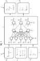
- the figure 1 shows a schematic sequence of a state estimation 21 for a power grid using a neural network 1 designed and trained according to the present invention.
- the neural network 1 is represented symbolically by its neurons (circles) and their connections (arrows).
- the neural network 1 has an input layer 14 with a number of inputs 41 , one or more hidden layers 11 and an output layer 12 with a number of outputs 21 .
- the neural network 1 calculates the outputs 21 via its hidden layers 11, which correspond to the outputs 21 of the neural network.
- the outputs or outputs 21 then correspond to the state estimate for the power grid for the inputs 41 that are supplied, so that the state estimate is identified by the same reference number 21 .
- Input values or input data which must be supplied to the inputs 41 of the neural network 1, are therefore required to calculate the state estimate 21.
- the inputs 41 can be identified with these data/values, since a fixed input 41 is assigned to each specific value, for example a voltage value.
- the amplitudes of harmonics 42 of the measurement signals, rise times 42 within the measurement signals and/or fall times 42 within the measurement signals are used as inputs 41 .
- these inputs according to the invention that is to say the amplitudes of harmonics, the rise times and/or the fall times are combined by box 42 so that they have the same reference number 42 in the present case.
- ratios of amplitudes of harmonics within the same measurement signal and/or across different measurement signals can be used as inputs 41 .
- the measurement signals are recorded for the state estimation 21 on the power grid, in particular at nodes of the power grid.
- the detection takes place within a time range, with the state estimate 21 then being calculated for the stated time range.
- a time-resolved state can be estimated based on currently detected measurement signals.
- the measurement signals can be voltage signals, current signals, active power signals and/or reactive power signals.
- the measurement signals can record the voltage, the current, the active power and/or the reactive power (measured variables) at the respective nodes and/or branches of the power grid within a fixed or specific time range.
- a time course of the respective measured variable is recorded at one or more nodes of the power grid. If the named time ranges are sufficiently short and such a measured-value-based or measured-signal-based state estimation 21 takes place for each time range by means of the neural network 1, then a state estimation 21 is achieved in real time.
- the amplitudes of the harmonics are typically determined by means of a Fourier transformation of the respective measurement signal.
- the Fourier transform of the measurement signals is calculated, for example using an FFT.
- the spectral power density of the measurement signal ie the spectrum of the measurement signal, could be determined. This can be done using the autocorrelation of the measurement signal.
- the frequency spectrum of the measurement signal is calculated using the Fourier transform of the measurement signal.
- the absolute value of the frequency spectrum is referred to as the amplitude spectrum and, like the spectral power density, can also be used to determine the amplitudes of the harmonics.
- spectral, ie frequency-dependent data is determined from the measurement signal, by means of which it is possible to determine the harmonics and their associated amplitudes.
- a particularly preferred means for this is the Fourier transformation and/or the calculation of the spectral power density.
- the state is estimated 21 based on current measurement data or its associated current spectral data.
- rise times and/or fall times within the measurement signals are used as inputs 41 as an alternative or in addition, these can be determined from the measurement signals using the method described above, ie using a Pade-Laplace method.
- the determined rise times and/or descent times are also fed to the associated inputs 41 of the neural network 1 for state estimation 21 .
- the peak amplitudes (poles of the Pade-Laplace transform) are particularly relevant here, since they correspond to the characteristic run-up times (rise times) or run-down times (fall times) of the respective systems.
- heat pumps or the charging of e-cars have such characteristic times that can be determined using the Laplace transform and the subsequent determination of the (best) Pade approximant.
- these are preferably also used as fingerprints for learning the neural network 1 and analogously for calculating the state estimate 21 .
- the measurement signals recorded are additionally used as inputs 41 for the neural network 1 .
- the index t indicates the respective time dependency of the variables mentioned. In the figure 1 the above variables or input variables are brought together within block 44 .
- exogenous parameters such as temperatures T n,t , geographical coordinates and/or time data ( EGHI ,n,t ) and/or weather data and/or historical network states can be used as inputs when calculating the state estimate.
- exogenous parameters such as temperatures T n,t , geographical coordinates and/or time data ( EGHI ,n,t ) and/or weather data and/or historical network states can be used as inputs when calculating the state estimate.
- directly known voltage profiles over time of certain systems, such as heat pumps could continue to be used. Thus, these quantities mentioned must also be used when training the neural network 1 be provided. Additional parameters or data can be provided.
- the state estimate 21 of the power grid can be read at the outputs 21 of the neural network 1 .
- at the node points (engl. Node Voltages) as well as the branch currents I nn',t (engl. Branch Currents) between the nodes n and n' (at the respective point in time or within the respective time range) based on the respective inputs/input data 41 by means of the neural network 1 is calculated.
- the calculated node voltages are shown in the figure 1 summarized and identified by box 22.
- the calculated branch currents are summarized and identified by box 24 here.
- the figure 2 shows a diagram to illustrate the spectral data (harmonics) of a measurement signal 4.
- the left diagram in figure 2 shows an exemplary time measurement signal 4 of the voltage at a node of the power grid.
- the time is plotted in arbitrary units on the abscissa 100 of the left-hand diagram.
- the magnitude of the voltage is plotted in arbitrary units on the ordinate 101 of the diagram on the left.
- the measurement signal 4 has a fundamental frequency of 50 Hz. Furthermore, the measurement signal has higher harmonic components that are not directly recognizable from the time profile of the measurement signal. If, for example, a Fourier transformation 104 of the measurement signal 4 is carried out, then in particular the amplitude spectrum of the measurement signal 4 can be calculated.
- the amplitude spectrum determined from the measurement signal 4 by means of a Fourier transformation is shown.
- this shows several spikes that correspond to the harmonics.
- Each spike marks a harmonic, these being different have amplitudes.
- the harmonics are 100 Hz, 150 Hz, 200 Hz, 250 Hz, 300 Hz, 350 Hz and 400 Hz in the diagram shown on the right.
- the amplitude of the first harmonic (100 Hz) and the second harmonic ( 100 Hz) are the largest in this case.
- the amplitudes of the harmonics for the respective measurement signal can thus be determined by means of the amplitude spectrum and used for the state estimation by means of the neural network or for its training. Furthermore, a ratio of amplitudes of the harmonics can preferably be used for the state estimation or its training.
- spectral data that is to say higher harmonics
- characteristic times which can be determined, for example, using a Pade-Laplace transform, are used as an alternative or in addition for the training and thus for the state estimation.
- the input variables according to the invention form a fingerprint for the systems connected to the electricity network, so that the estimation of the neural network with regard to the network state is significantly improved by the present invention.
- a further advantage of the present invention is that an improved estimation of the grid state (state estimation) can be achieved without further or larger installations or investments in the electricity grid.
- the method according to the invention also saves resources, since a Fourier transformation/Laplace transformation can be implemented efficiently or can already be carried out directly by the measuring device.
- an improved state estimation or grid state estimation is provided, in particular for heavily underdetermined power grids, such as medium-voltage or low-voltage power grids.
- improved intelligent control of the power grid can be achieved, especially with regard to digital power grids and renewable energies.
Priority Applications (5)
| Application Number | Priority Date | Filing Date | Title |
|---|---|---|---|
| EP20204648.8A EP3993207A1 (fr) | 2020-10-29 | 2020-10-29 | Évaluation de l'état d'un réseau électrique |
| US18/250,576 US20230400483A1 (en) | 2020-10-29 | 2021-10-19 | State Estimation of a Power Network |
| PCT/EP2021/078864 WO2022089983A1 (fr) | 2020-10-29 | 2021-10-19 | Estimation d'état d'un réseau électrique |
| EP21797999.6A EP4211642A1 (fr) | 2020-10-29 | 2021-10-19 | Estimation d'état d'un réseau électrique |
| CN202180073685.0A CN116508221A (zh) | 2020-10-29 | 2021-10-19 | 电网的状态估计 |
Applications Claiming Priority (1)
| Application Number | Priority Date | Filing Date | Title |
|---|---|---|---|
| EP20204648.8A EP3993207A1 (fr) | 2020-10-29 | 2020-10-29 | Évaluation de l'état d'un réseau électrique |
Publications (1)
| Publication Number | Publication Date |
|---|---|
| EP3993207A1 true EP3993207A1 (fr) | 2022-05-04 |
Family
ID=73039870
Family Applications (2)
| Application Number | Title | Priority Date | Filing Date |
|---|---|---|---|
| EP20204648.8A Withdrawn EP3993207A1 (fr) | 2020-10-29 | 2020-10-29 | Évaluation de l'état d'un réseau électrique |
| EP21797999.6A Pending EP4211642A1 (fr) | 2020-10-29 | 2021-10-19 | Estimation d'état d'un réseau électrique |
Family Applications After (1)
| Application Number | Title | Priority Date | Filing Date |
|---|---|---|---|
| EP21797999.6A Pending EP4211642A1 (fr) | 2020-10-29 | 2021-10-19 | Estimation d'état d'un réseau électrique |
Country Status (4)
| Country | Link |
|---|---|
| US (1) | US20230400483A1 (fr) |
| EP (2) | EP3993207A1 (fr) |
| CN (1) | CN116508221A (fr) |
| WO (1) | WO2022089983A1 (fr) |
Citations (2)
| Publication number | Priority date | Publication date | Assignee | Title |
|---|---|---|---|---|
| EP3336995A1 (fr) * | 2016-12-19 | 2018-06-20 | Siemens Aktiengesellschaft | Procédé, dispositif de commande et système de détermination de valeurs d'état pour décrire des états de fonctionnement dans un sous-réseau d'un réseau de distribution d'énergie |
| EP3518369A1 (fr) | 2018-01-30 | 2019-07-31 | Siemens Aktiengesellschaft | Méthode et dispositif pour contrôler le transfert de puissance électrique et réseau électrique |
-
2020
- 2020-10-29 EP EP20204648.8A patent/EP3993207A1/fr not_active Withdrawn
-
2021
- 2021-10-19 WO PCT/EP2021/078864 patent/WO2022089983A1/fr active Application Filing
- 2021-10-19 CN CN202180073685.0A patent/CN116508221A/zh active Pending
- 2021-10-19 US US18/250,576 patent/US20230400483A1/en active Pending
- 2021-10-19 EP EP21797999.6A patent/EP4211642A1/fr active Pending
Patent Citations (2)
| Publication number | Priority date | Publication date | Assignee | Title |
|---|---|---|---|---|
| EP3336995A1 (fr) * | 2016-12-19 | 2018-06-20 | Siemens Aktiengesellschaft | Procédé, dispositif de commande et système de détermination de valeurs d'état pour décrire des états de fonctionnement dans un sous-réseau d'un réseau de distribution d'énergie |
| EP3518369A1 (fr) | 2018-01-30 | 2019-07-31 | Siemens Aktiengesellschaft | Méthode et dispositif pour contrôler le transfert de puissance électrique et réseau électrique |
Also Published As
| Publication number | Publication date |
|---|---|
| US20230400483A1 (en) | 2023-12-14 |
| EP4211642A1 (fr) | 2023-07-19 |
| WO2022089983A1 (fr) | 2022-05-05 |
| CN116508221A (zh) | 2023-07-28 |
Similar Documents
| Publication | Publication Date | Title |
|---|---|---|
| EP3660523B1 (fr) | Procédé, dispositif et système destinés à déterminer l'emplacement d'un défaut sur une ligne d'un réseau d'alimentation d'énergie électrique | |
| EP3107174B1 (fr) | Procédé, dispositif de commande et système de fonctionnement d'un sous-réseau d'un réseau de distribution d'énergie | |
| EP3336995B1 (fr) | Procédé, dispositif de commande et système de détermination de valeurs d'état pour décrire des états de fonctionnement dans un sous-réseau d'un réseau de distribution d'énergie | |
| EP3042428B1 (fr) | Dispositif et procédé permettant de commander la stabilité d'un réseau régional pourvu d'un transformateur de réseau régional réglable | |
| EP3345294B1 (fr) | Procédé de fonctionnement d'un onduleur et onduleur | |
| EP1941285A1 (fr) | Procédé d élaboration d une serie de données et appareil de terrain ainsi que système de détection de la qualité électro-énergétique d un réseau d alimentation en énergie | |
| DE102016207454A1 (de) | Einrichtung für Wahrscheinlichkeitsvorhersagen, mit einer solchen Einrichtung ausgestattetes Energieübertragungs- und/oder Energieverteilnetz und Verfahren für dessen Betrieb | |
| WO2015063098A1 (fr) | Onduleur et procédé de détection permettant à un onduleur d'identifier un défaut du réseau | |
| DE102017101413A1 (de) | Verfahren zur Einsatzplanung eines elektrischen Systems zur Energieversorgung | |
| DE102018116446A1 (de) | Windenergiesystem und Verfahren zum Erkennen niederfrequenter Schwingungen in einem elektrischen Versorgungsnetz | |
| EP3751699B1 (fr) | Procédé et dispositif d'estimation d'un état d'un réseau de distribution d'énergie | |
| EP3993207A1 (fr) | Évaluation de l'état d'un réseau électrique | |
| EP2834898B1 (fr) | Procédé de détermination de points de mesure dans des réseaux à basse tension et sous-système de gestion de réseau servant à mettre en oeuvre ce procédé | |
| EP3340413B1 (fr) | Procédé, dispositif de commande et système de détermination de données d'état d'un réseau d'alimentation électrique | |
| EP2781005A1 (fr) | Réseau de distribution d'énergie | |
| EP2618458B1 (fr) | Procédé destiné à détecter des états de commutation dans des réseaux d'alimentation en énergie et système destiné à l'exécution du procédé | |
| DE102018124612A1 (de) | Steuerung eines lokalen Netzbereichs zur Realisierung einer Local Energy Community mit Fahrplan | |
| EP3510683B1 (fr) | Procédé et système de régulation décentralisée longue portée | |
| EP3667851A1 (fr) | Création des modèles dynamiques de noeuds de réseau dans un réseau de distribution faible et / ou moyenne tension | |
| DE102016112005A1 (de) | Verfahren zur Auslegung des Netzschutzes eines elektrischen Niederspannungsversorgungsnetzes | |
| EP2429061A1 (fr) | Procédé de pronostic de perte d'énergie amélioré dans un réseau de transmission | |
| WO2024022814A1 (fr) | Procédé et unité de commande pour commander un réseau électrique | |
| DE102020206672A1 (de) | Niederspannungsverteilnetz, Stromnetz, Verfahren zum Betreiben eines Niederspannungsverteilnetzes | |
| EP3131168A1 (fr) | Procede et systeme pour la determination de points de mesure dans un reseau d'energie | |
| EP4075622A1 (fr) | Détermination de la topologie réseau d'un réseau électrique, ainsi que régulation d'un réseau électrique |
Legal Events
| Date | Code | Title | Description |
|---|---|---|---|
| PUAI | Public reference made under article 153(3) epc to a published international application that has entered the european phase |
Free format text: ORIGINAL CODE: 0009012 |
|
| STAA | Information on the status of an ep patent application or granted ep patent |
Free format text: STATUS: THE APPLICATION HAS BEEN PUBLISHED |
|
| AK | Designated contracting states |
Kind code of ref document: A1 Designated state(s): AL AT BE BG CH CY CZ DE DK EE ES FI FR GB GR HR HU IE IS IT LI LT LU LV MC MK MT NL NO PL PT RO RS SE SI SK SM TR |
|
| STAA | Information on the status of an ep patent application or granted ep patent |
Free format text: STATUS: THE APPLICATION IS DEEMED TO BE WITHDRAWN |
|
| 18D | Application deemed to be withdrawn |
Effective date: 20221105 |