EP3993144A2 - Power storage cell and method of manufacturing same - Google Patents
Power storage cell and method of manufacturing same Download PDFInfo
- Publication number
- EP3993144A2 EP3993144A2 EP21199226.8A EP21199226A EP3993144A2 EP 3993144 A2 EP3993144 A2 EP 3993144A2 EP 21199226 A EP21199226 A EP 21199226A EP 3993144 A2 EP3993144 A2 EP 3993144A2
- Authority
- EP
- European Patent Office
- Prior art keywords
- insulating film
- heat
- power storage
- top surface
- exterior container
- Prior art date
- Legal status (The legal status is an assumption and is not a legal conclusion. Google has not performed a legal analysis and makes no representation as to the accuracy of the status listed.)
- Pending
Links
Images





Classifications
-
- H—ELECTRICITY
- H01—ELECTRIC ELEMENTS
- H01M—PROCESSES OR MEANS, e.g. BATTERIES, FOR THE DIRECT CONVERSION OF CHEMICAL ENERGY INTO ELECTRICAL ENERGY
- H01M10/00—Secondary cells; Manufacture thereof
- H01M10/60—Heating or cooling; Temperature control
- H01M10/65—Means for temperature control structurally associated with the cells
- H01M10/658—Means for temperature control structurally associated with the cells by thermal insulation or shielding
-
- H—ELECTRICITY
- H01—ELECTRIC ELEMENTS
- H01M—PROCESSES OR MEANS, e.g. BATTERIES, FOR THE DIRECT CONVERSION OF CHEMICAL ENERGY INTO ELECTRICAL ENERGY
- H01M50/00—Constructional details or processes of manufacture of the non-active parts of electrochemical cells other than fuel cells, e.g. hybrid cells
- H01M50/10—Primary casings; Jackets or wrappings
- H01M50/116—Primary casings; Jackets or wrappings characterised by the material
- H01M50/124—Primary casings; Jackets or wrappings characterised by the material having a layered structure
- H01M50/1245—Primary casings; Jackets or wrappings characterised by the material having a layered structure characterised by the external coating on the casing
-
- H—ELECTRICITY
- H01—ELECTRIC ELEMENTS
- H01M—PROCESSES OR MEANS, e.g. BATTERIES, FOR THE DIRECT CONVERSION OF CHEMICAL ENERGY INTO ELECTRICAL ENERGY
- H01M10/00—Secondary cells; Manufacture thereof
- H01M10/04—Construction or manufacture in general
-
- H—ELECTRICITY
- H01—ELECTRIC ELEMENTS
- H01G—CAPACITORS; CAPACITORS, RECTIFIERS, DETECTORS, SWITCHING DEVICES, LIGHT-SENSITIVE OR TEMPERATURE-SENSITIVE DEVICES OF THE ELECTROLYTIC TYPE
- H01G11/00—Hybrid capacitors, i.e. capacitors having different positive and negative electrodes; Electric double-layer [EDL] capacitors; Processes for the manufacture thereof or of parts thereof
- H01G11/78—Cases; Housings; Encapsulations; Mountings
-
- H—ELECTRICITY
- H01—ELECTRIC ELEMENTS
- H01M—PROCESSES OR MEANS, e.g. BATTERIES, FOR THE DIRECT CONVERSION OF CHEMICAL ENERGY INTO ELECTRICAL ENERGY
- H01M10/00—Secondary cells; Manufacture thereof
- H01M10/60—Heating or cooling; Temperature control
- H01M10/64—Heating or cooling; Temperature control characterised by the shape of the cells
- H01M10/647—Prismatic or flat cells, e.g. pouch cells
-
- H—ELECTRICITY
- H01—ELECTRIC ELEMENTS
- H01M—PROCESSES OR MEANS, e.g. BATTERIES, FOR THE DIRECT CONVERSION OF CHEMICAL ENERGY INTO ELECTRICAL ENERGY
- H01M50/00—Constructional details or processes of manufacture of the non-active parts of electrochemical cells other than fuel cells, e.g. hybrid cells
- H01M50/10—Primary casings; Jackets or wrappings
-
- H—ELECTRICITY
- H01—ELECTRIC ELEMENTS
- H01M—PROCESSES OR MEANS, e.g. BATTERIES, FOR THE DIRECT CONVERSION OF CHEMICAL ENERGY INTO ELECTRICAL ENERGY
- H01M50/00—Constructional details or processes of manufacture of the non-active parts of electrochemical cells other than fuel cells, e.g. hybrid cells
- H01M50/10—Primary casings; Jackets or wrappings
- H01M50/102—Primary casings; Jackets or wrappings characterised by their shape or physical structure
- H01M50/103—Primary casings; Jackets or wrappings characterised by their shape or physical structure prismatic or rectangular
-
- H—ELECTRICITY
- H01—ELECTRIC ELEMENTS
- H01M—PROCESSES OR MEANS, e.g. BATTERIES, FOR THE DIRECT CONVERSION OF CHEMICAL ENERGY INTO ELECTRICAL ENERGY
- H01M50/00—Constructional details or processes of manufacture of the non-active parts of electrochemical cells other than fuel cells, e.g. hybrid cells
- H01M50/10—Primary casings; Jackets or wrappings
- H01M50/14—Primary casings; Jackets or wrappings for protecting against damage caused by external factors
- H01M50/141—Primary casings; Jackets or wrappings for protecting against damage caused by external factors for protecting against humidity
-
- H—ELECTRICITY
- H01—ELECTRIC ELEMENTS
- H01M—PROCESSES OR MEANS, e.g. BATTERIES, FOR THE DIRECT CONVERSION OF CHEMICAL ENERGY INTO ELECTRICAL ENERGY
- H01M50/00—Constructional details or processes of manufacture of the non-active parts of electrochemical cells other than fuel cells, e.g. hybrid cells
- H01M50/20—Mountings; Secondary casings or frames; Racks, modules or packs; Suspension devices; Shock absorbers; Transport or carrying devices; Holders
- H01M50/204—Racks, modules or packs for multiple batteries or multiple cells
- H01M50/207—Racks, modules or packs for multiple batteries or multiple cells characterised by their shape
- H01M50/209—Racks, modules or packs for multiple batteries or multiple cells characterised by their shape adapted for prismatic or rectangular cells
-
- H—ELECTRICITY
- H01—ELECTRIC ELEMENTS
- H01M—PROCESSES OR MEANS, e.g. BATTERIES, FOR THE DIRECT CONVERSION OF CHEMICAL ENERGY INTO ELECTRICAL ENERGY
- H01M50/00—Constructional details or processes of manufacture of the non-active parts of electrochemical cells other than fuel cells, e.g. hybrid cells
- H01M50/20—Mountings; Secondary casings or frames; Racks, modules or packs; Suspension devices; Shock absorbers; Transport or carrying devices; Holders
- H01M50/233—Mountings; Secondary casings or frames; Racks, modules or packs; Suspension devices; Shock absorbers; Transport or carrying devices; Holders characterised by physical properties of casings or racks, e.g. dimensions
- H01M50/24—Mountings; Secondary casings or frames; Racks, modules or packs; Suspension devices; Shock absorbers; Transport or carrying devices; Holders characterised by physical properties of casings or racks, e.g. dimensions adapted for protecting batteries from their environment, e.g. from corrosion
-
- H—ELECTRICITY
- H01—ELECTRIC ELEMENTS
- H01G—CAPACITORS; CAPACITORS, RECTIFIERS, DETECTORS, SWITCHING DEVICES, LIGHT-SENSITIVE OR TEMPERATURE-SENSITIVE DEVICES OF THE ELECTROLYTIC TYPE
- H01G9/00—Electrolytic capacitors, rectifiers, detectors, switching devices, light-sensitive or temperature-sensitive devices; Processes of their manufacture
- H01G9/0029—Processes of manufacture
-
- H—ELECTRICITY
- H01—ELECTRIC ELEMENTS
- H01G—CAPACITORS; CAPACITORS, RECTIFIERS, DETECTORS, SWITCHING DEVICES, LIGHT-SENSITIVE OR TEMPERATURE-SENSITIVE DEVICES OF THE ELECTROLYTIC TYPE
- H01G9/00—Electrolytic capacitors, rectifiers, detectors, switching devices, light-sensitive or temperature-sensitive devices; Processes of their manufacture
- H01G9/004—Details
- H01G9/08—Housing; Encapsulation
-
- Y—GENERAL TAGGING OF NEW TECHNOLOGICAL DEVELOPMENTS; GENERAL TAGGING OF CROSS-SECTIONAL TECHNOLOGIES SPANNING OVER SEVERAL SECTIONS OF THE IPC; TECHNICAL SUBJECTS COVERED BY FORMER USPC CROSS-REFERENCE ART COLLECTIONS [XRACs] AND DIGESTS
- Y02—TECHNOLOGIES OR APPLICATIONS FOR MITIGATION OR ADAPTATION AGAINST CLIMATE CHANGE
- Y02E—REDUCTION OF GREENHOUSE GAS [GHG] EMISSIONS, RELATED TO ENERGY GENERATION, TRANSMISSION OR DISTRIBUTION
- Y02E60/00—Enabling technologies; Technologies with a potential or indirect contribution to GHG emissions mitigation
- Y02E60/10—Energy storage using batteries
-
- Y—GENERAL TAGGING OF NEW TECHNOLOGICAL DEVELOPMENTS; GENERAL TAGGING OF CROSS-SECTIONAL TECHNOLOGIES SPANNING OVER SEVERAL SECTIONS OF THE IPC; TECHNICAL SUBJECTS COVERED BY FORMER USPC CROSS-REFERENCE ART COLLECTIONS [XRACs] AND DIGESTS
- Y02—TECHNOLOGIES OR APPLICATIONS FOR MITIGATION OR ADAPTATION AGAINST CLIMATE CHANGE
- Y02P—CLIMATE CHANGE MITIGATION TECHNOLOGIES IN THE PRODUCTION OR PROCESSING OF GOODS
- Y02P70/00—Climate change mitigation technologies in the production process for final industrial or consumer products
- Y02P70/50—Manufacturing or production processes characterised by the final manufactured product
Definitions
- the present disclosure relates to a power storage cell and a method of manufacturing the power storage cell.
- a housing of a power storage cell has been conventionally covered with an insulating film.
- An exemplary conventional structure is described in Japanese Patent Laying-Open No. 2013-33668 (PTL 1).
- a juncture is formed at the insulating film.
- the juncture can be closed to achieve insulation protection.
- the insulating film may be contracted to form a hard lump.
- An object of the present disclosure is to provide a power storage cell and a method of manufacturing the power storage cell so as to improve a degree of freedom in designing a peripheral member while achieving insulation protection.
- a power storage cell includes: an exterior container having a top surface, a bottom surface, and a side surface located between the top surface and the bottom surface; and an insulating film that covers at least the side surface of the exterior container.
- the insulating film has a juncture on the side surface of the exterior container, and the juncture on the side surface is heat-sealed.
- a heat-sealed portion on the side surface has a termination portion at a position separated from the top surface or the bottom surface of the exterior container.
- a method of manufacturing a power storage cell includes: providing an insulating film on at least a side surface of an exterior container having a top surface, a bottom surface, and the side surface, the side surface being located between the top surface and the bottom surface; and heat-sealing a juncture of the insulating film on the side surface.
- the heat-sealing includes dissipating heat from a second region of the side surface while heat-sealing a first region of the side surface, the second region being located in a vicinity of the top surface or the bottom surface of the exterior container.
- Fig. 1 is a diagram showing a basic configuration of a battery pack 1.
- Fig. 2 is a diagram showing battery cells 100 and end plates 200 included in battery pack 1.
- battery pack 1 serving as an exemplary "power storage module” includes battery cells 100, end plates 200, and a restraining member 300.
- battery cell 100 is a lithium ion battery, but battery cell 100 may be another battery such as a nickel-metal hydride battery.
- the "power storage module” is not limited to battery pack 1, and a capacitor may be used as a "power storage cell” instead of battery cell 100, for example.
- the plurality of battery cells 100 are provided side by side in a Y axis direction (arrangement direction). Each of battery cells 100 includes an electrode terminal 110. A separator (not shown) is interposed between the plurality of battery cells 100. The plurality of battery cells 100 sandwiched between two end plates 200 are pressed by end plates 200, and are restrained between two end plates 200.
- End plates 200 are disposed at both ends of battery pack 1 in the Y axis direction (arrangement direction). End plates 200 are fixed to a base such as a case that accommodates battery pack 1.
- Restraining member 300 connects two end plates 200 to each other. Restraining member 300 is attached to two end plates 200.
- Restraining member 300 is engaged with end plates 200 with compression force in the Y axis direction being applied to a stack of the plurality of battery cells 100 and end plates 200, and then the compression force is released, thereby exerting tensile force on restraining member 300 that connects two end plates 200 to each other. As a counteraction, restraining member 300 presses two end plates 200 in a direction of bringing them closer to each other.
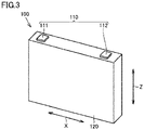
- Fig. 3 is a diagram showing each battery cell 100 in battery pack 1. As shown in Fig. 3 , battery cell 100 is formed to have a flat rectangular parallelepiped shape. Electrode terminal 110 includes a positive electrode terminal 111 and a negative electrode terminal 112. Electrode terminal 110 is formed on a housing 120 having a prismatic shape. An electrode assembly (not shown) and an electrolyte solution (not shown) are accommodated in housing 120.
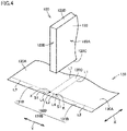
- Fig. 4 is a diagram showing an exemplary shape of an insulating film 130.
- housing 120 of battery cell 100 is covered with insulating film 130.
- the insulating film is composed of an insulating material such as polyethylene terephthalate (PET).
- housing 120 (exterior container) has side surfaces 120A (long side surfaces), side surfaces 120B (short side surfaces), a bottom surface 120C, and a top surface 120D. Side surfaces 120A, 120B are located between bottom surface 120C and top surface 120D.
- Insulating film 130 covers side surfaces 120A, 120B and bottom surface 120C of housing 120. As shown in Figs. 5 to 8 , side surfaces 120A, 120B and bottom surface 120C of housing 120 are covered by folding insulating film 130 that is in the form of a sheet. A portion of insulating film 130 may extend onto top surface 120D of housing 120, or may not reach top surface 120D.
- Insulating film 130 includes: side surface covering portions 130A that cover side surfaces 120A of housing 120; side surface covering portions 130B that cover side surfaces 120B of housing 120; and a bottom surface covering portion 130C that covers bottom surface 120C of housing 120.
- bottom surface covering portion 130C is provided between the pair of side surface covering portions 130A, and side surface covering portions 130B protrudes from side surface covering portions 130A and bottom surface covering portion 130C.
- Each of side surface covering portions 130B includes: first portions 131B protruding outward from the respective side edges of side surface covering portions 130A; and a second portion 132B protruding outward from the side edge of bottom surface covering portion 130C.
- each first portion 131B and second portion 132B of side surface covering portion 130B are not separated from each other at a boundary therebetween and are continuous to each other. Therefore, in a state in which insulating film 130 is folded along housing 120, no pinhole is formed at each intersection K.
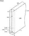
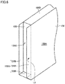
- FIG. 5 to 8 is a diagram showing a step of covering housing 120 of battery cell 100 with insulating film 130. As shown in Figs. 5 to 8 , side surfaces 120A, 120B and bottom surface 120C of housing 120 are covered by folding insulating film 130 that is in the form of a sheet.
- insulating film 130 is folded inward at a boundary line L1 between each side surface covering portion 130A and bottom surface covering portion 130C, thereby covering bottom surface 120C of housing 120 with bottom surface covering portion 130C and thereby covering side surface 120A of housing 120 with side surface covering portion 130A ( Fig. 5 ). Further, insulating film 130 is folded inward at a boundary line L2 between each second portion 132B and bottom surface covering portion 130C, and insulating film 130 is folded inward at a boundary line L3 between each first portion 131B and each side surface covering portion 130A.
- insulating film 130 is folded at a boundary line L4 between first portion 131B and second portion 132B and at a folding line S1 on first portion 131B, with the result that first portion 131B and second portion 132B are layered on side surface 120B of housing 120 ( Figs. 6 and 7 ).
- first portion 131B and second portion 132B on side surface 120B is heated and welded (heat-sealed) to have a watertight structure. That is, junctures 130 ⁇ of the layered portion shown in Fig. 8 are closed by heat-sealing insulating film 130. Thus, entire side surface 120B of housing 120 is covered with insulating film 130, thereby securing electrical insulation protection.
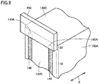
- Fig. 9 is a diagram showing a shape of each of heat-sealed portions 140 of insulating film 130 (overlapped portions of insulating film 130 welded by the heat-sealing).
- each of heat-sealed portions 140 is formed to extend in a height direction (Z axis direction) from bottom surface 120C toward top surface 120D along juncture 130 ⁇ of insulating film 130.
- the plurality of heat-sealed portions 140 may be formed to extend along the Z axis direction.
- Each of heat-sealed portions 140 is terminated at a position (termination portion 140A) separated from top surface 120D of housing 120. Also on the bottom surface 120C side, heat-sealed portion 140 may be terminated at a position separated from bottom surface 120C of housing 120. That is, side surface covering portion 130B of insulating film 130 includes: a first region 10 that is heat-sealed; and a second region 20 that is not heat-sealed. Second region 20 is not heat-sealed but can secure insulation protection comparable to insulation protection secured by first region 10.
- second region 20 that is not heat-sealed is provided in the vicinity of top surface 120D of housing 120, a lump of insulating film 130 contracted by the heat-sealing can be suppressed from being formed in the vicinity of top surface 120D of housing 120 to interfere with a peripheral member such as a bus bar module, and a degree of freedom in designing the peripheral member can be suppressed from being decreased to avoid the interference.
- heat-sealing side surface covering portion 130B heat is dissipated by bringing a jig 400 for promoting heat dissipation into contact with second region 20 located in the vicinity of top surface 120D while heat-sealing first region 10 located on the center side in the Z axis direction by bringing a heat plate (welding plate) into contact with first region 10.
- a heat plate welding plate
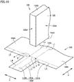
- Fig. 10 is a diagram showing a modification of the shape of insulating film 130.
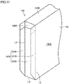
- Fig. 11 is a diagram showing a step of covering housing 120 of battery cell 100 with insulating film 130 shown in Fig. 10 .
- each of side surface covering portions 130B of insulating film 130 includes first portions 131B, second portions 132B, and a third portion 133B.
- First portions 131A and second portions 132B protrude from the respective side edges of side surface covering portions 130A.
- Third portion 133B protrudes from the side edge of bottom surface covering portion 130C.
- side surfaces 120A of housing 120 are covered with side surface covering portions 130A
- side surfaces 120B are covered with side surface covering portions 130B
- bottom surface 120C is covered with bottom surface covering portion 130C.
- first portions 131B, second portions 132B, and third portion 133B of side surface covering portion 130B are layered and this layered portion is welded (heat-sealed) to close the junctures.
- each first portion 131B of side surface covering portion 130B in the X axis direction and the width of each second portion 132B of side surface covering portion 130B in the Y axis direction are equal to each other in a state in which insulating film 130 is unfolded, insulating film 130 is folded at folding line S1 in the boundary portion therebetween, and first portion 131B and second portion 132B are layered on each other.
- the lengths of each second portion 132B and third portion 133B in the X axis direction are shorter than the length of first portion 131B in the Y axis direction. Therefore, when insulating film 130 is folded as shown in Fig. 11 , first portion 131B of side surface covering portion 130B reaches the boundary between side surface 120B and top surface 120D of housing 120, whereas second portion 132B and third portion 133B do not reach top surface 120D.
- insulating film 130 When providing insulating film 130 on housing 120, insulating film 130 is folded inward at boundary line L1 between side surface covering portion 130A and bottom surface covering portion 130C with bottom surface 120C of housing 120 facing bottom surface covering portion 130C of the insulating film as shown in Fig. 10 .
- side surface 120A of housing 120 is covered with side surface covering portion 130A
- bottom surface 120C of housing 120 is covered with bottom surface covering portion 130C.
- insulating film 130 is folded inward at boundary line L2 between third portion 133B of side surface covering portion 130B and bottom surface covering portion 130C.
- side surface 120B of housing 120 is covered with third portion 133B of side surface covering portion 130B.
- insulating film 130 is folded inward at folding line S1 that is a boundary line between first portion 131B and second portion 132B of side surface covering portion 130B, with the result that first portion 131B and second portion 132B of side surface covering portion 130B are layered on each other.
- first portion 131B and second portion 132B of side surface covering portion 130B are folded inward at boundary line L3 with side surface covering portion 130A, with the result that first portion 131B and second portion 132B layered on each other are folded to be on the surface of third portion 133B.
- the layered portion of first portion 131B, second portion 132B, and third portion 133B is heated and is welded (heat-sealed) to have a water-tight structure.
- Fig. 12 is a diagram showing jigs 500 used in the heat-sealing step.
- jigs 500 are provided at both end portions of top surface 120D of housing 120 in the X axis direction, and jigs 500 can prevent those portions from being exposed to warm air in the step of heat-sealing insulating film 130.
- a lump of insulating film 130 contacted can be suppressed from being formed at a shoulder portion of housing 120 to interfere with the peripheral member, and the degree of freedom in designing the peripheral member can be suppressed from being decreased to avoid the interference.
- Fig. 13 is a diagram showing a battery cell 100 according to a modification.
- a member 600 is provided on side surface covering portion 130B of insulating film 130.
- Member 600 is constituted of a separate component such as a separator.
- Insulating film 130 is provided on housing 120 so as to be terminated slightly below top surface 120D of housing 120.
- Member 600 presses side surface covering portion 130B of insulating film 130 to suppress occurrence of further detachment of insulating film 130 when secondary contraction of insulating film 130 occurs due to a use environment.
- Fig. 14 is a diagram showing a structure of an upper corner portion of battery cell 100 located at an end portion in the stacking direction (Y axis direction). As shown in Fig. 14 , a separator 700 is provided between battery cell 100 at the end portion and end plate 200. End plate 200 is composed of a conductor such as aluminum or cast iron. Separator 700 is composed of an insulating material such as a resin, a rubber, or an elastomer.
- insulating film 130 is provided to be terminated at a position lower than top surface 120D of housing 120 by a predetermined height H (for example, about 0.5 mm). It is necessary to secure a predetermined creepage distance L (for example, about 7 mm) from the upper end of insulating film 130 to end plate 200. Therefore, it is necessary to suppress detachment of insulating film 130.
- a predetermined height H for example, about 0.5 mm. It is necessary to secure a predetermined creepage distance L (for example, about 7 mm) from the upper end of insulating film 130 to end plate 200. Therefore, it is necessary to suppress detachment of insulating film 130.
- battery cell 100 of the present embodiment since a lump of insulating film 130 thermally contracted can be suppressed from being formed at the shoulder portion of housing 120 as described above, the degree of freedom in designing the peripheral member around battery cell 100 can be improved while achieving insulation protection.
- heat-sealed portion 140 is provided on side surface 120B; however, the position at which heat-sealed portion 140 is formed is not limited to side surface 120B. Also, in the present embodiment, it has been illustratively described that housing 120 having a prismatic shape is covered with insulating film 130; however, housing 120 of battery cell 100 may have a cylindrical shape.
Landscapes
- Chemical & Material Sciences (AREA)
- Chemical Kinetics & Catalysis (AREA)
- Electrochemistry (AREA)
- General Chemical & Material Sciences (AREA)
- Engineering & Computer Science (AREA)
- Manufacturing & Machinery (AREA)
- Power Engineering (AREA)
- Microelectronics & Electronic Packaging (AREA)
- Sealing Battery Cases Or Jackets (AREA)
- Battery Mounting, Suspending (AREA)
Abstract
Description
- This nonprovisional application is based on
Japanese Patent Application No. 2020-181627 filed on October 29, 2020 - The present disclosure relates to a power storage cell and a method of manufacturing the power storage cell.
- In order to achieve electrical insulation protection, a housing of a power storage cell has been conventionally covered with an insulating film. An exemplary conventional structure is described in
Japanese Patent Laying-Open No. 2013-33668 - When the housing is covered with the insulating film, a juncture is formed at the insulating film. By heat-sealing the juncture, the juncture can be closed to achieve insulation protection. However, when the insulating film is heat-sealed, the insulating film may be contracted to form a hard lump. When other components are designed to avoid interference with the lump, a degree of freedom in design is decreased, with the result that downsizing of an entire module including the power storage cell may be hindered.
- An object of the present disclosure is to provide a power storage cell and a method of manufacturing the power storage cell so as to improve a degree of freedom in designing a peripheral member while achieving insulation protection.
- A power storage cell according to the present disclosure includes: an exterior container having a top surface, a bottom surface, and a side surface located between the top surface and the bottom surface; and an insulating film that covers at least the side surface of the exterior container. The insulating film has a juncture on the side surface of the exterior container, and the juncture on the side surface is heat-sealed. A heat-sealed portion on the side surface has a termination portion at a position separated from the top surface or the bottom surface of the exterior container.
- A method of manufacturing a power storage cell according to the present disclosure includes: providing an insulating film on at least a side surface of an exterior container having a top surface, a bottom surface, and the side surface, the side surface being located between the top surface and the bottom surface; and heat-sealing a juncture of the insulating film on the side surface. The heat-sealing includes dissipating heat from a second region of the side surface while heat-sealing a first region of the side surface, the second region being located in a vicinity of the top surface or the bottom surface of the exterior container.
- The foregoing and other objects, features, aspects and advantages of the present invention will become more apparent from the following detailed description of the present invention when taken in conjunction with the accompanying drawings.
-
-
Fig. 1 is a diagram showing a basic configuration of a battery pack. -
Fig. 2 is a diagram showing battery cells and end plates in the battery pack shown inFig. 1 . -
Fig. 3 is a diagram showing each battery cell in the battery pack shown inFig. 1 . -
Fig. 4 is a diagram showing an exemplary shape of an insulating film. -
Fig. 5 is a first diagram showing a step of covering a housing of the battery cell with the insulating film shown inFig. 4 . -
Fig. 6 is a second diagram showing the step of covering the housing of the battery cell with the insulating film shown inFig. 4 . -
Fig. 7 is a third diagram showing the step of covering the housing of the battery cell with the insulating film shown inFig. 4 . -
Fig. 8 is a fourth diagram showing the step of covering the housing of the battery cell with the insulating film shown inFig. 4 . -
Fig. 9 is a diagram showing a shape of each of heat-sealed portions of the insulating film. -
Fig. 10 is a diagram showing a modification of the shape of the insulating film. -
Fig. 11 is a diagram showing a step of covering the housing of the battery cell with the insulating film shown inFig. 10 . -
Fig. 12 is a diagram showing exemplary jigs used in a heat-sealing step. -
Fig. 13 is a diagram showing a battery cell according to a modification. -
Fig. 14 is a diagram showing a structure of an upper corner portion of a battery cell located at an end portion in a stacking direction. - Hereinafter, embodiments of the present disclosure will be described. It should be noted that the same or corresponding portions are denoted by the same reference characters and may not be described repeatedly.
- It should be noted that in the embodiments described below, when reference is made to number, amount, and the like, the scope of the present disclosure is not necessarily limited to the number, amount, and the like unless otherwise stated particularly. Further, in the embodiments described below, each component is not necessarily essential to the present disclosure unless otherwise stated particularly.
-
Fig. 1 is a diagram showing a basic configuration of abattery pack 1.Fig. 2 is a diagram showingbattery cells 100 andend plates 200 included inbattery pack 1. - As shown in
Figs. 1 and 2 ,battery pack 1 serving as an exemplary "power storage module" includesbattery cells 100,end plates 200, and arestraining member 300. - As an example,
battery cell 100 is a lithium ion battery, butbattery cell 100 may be another battery such as a nickel-metal hydride battery. Further, in the present disclosure, the "power storage module" is not limited tobattery pack 1, and a capacitor may be used as a "power storage cell" instead ofbattery cell 100, for example. - The plurality of
battery cells 100 are provided side by side in a Y axis direction (arrangement direction). Each ofbattery cells 100 includes anelectrode terminal 110. A separator (not shown) is interposed between the plurality ofbattery cells 100. The plurality ofbattery cells 100 sandwiched between twoend plates 200 are pressed byend plates 200, and are restrained between twoend plates 200. -
End plates 200 are disposed at both ends ofbattery pack 1 in the Y axis direction (arrangement direction).End plates 200 are fixed to a base such as a case that accommodatesbattery pack 1. - Restraining
member 300 connects twoend plates 200 to each other. Restrainingmember 300 is attached to twoend plates 200. - Restraining
member 300 is engaged withend plates 200 with compression force in the Y axis direction being applied to a stack of the plurality ofbattery cells 100 andend plates 200, and then the compression force is released, thereby exerting tensile force on restrainingmember 300 that connects twoend plates 200 to each other. As a counteraction, restrainingmember 300 presses twoend plates 200 in a direction of bringing them closer to each other. -
Fig. 3 is a diagram showing eachbattery cell 100 inbattery pack 1. As shown inFig. 3 ,battery cell 100 is formed to have a flat rectangular parallelepiped shape.Electrode terminal 110 includes apositive electrode terminal 111 and anegative electrode terminal 112.Electrode terminal 110 is formed on ahousing 120 having a prismatic shape. An electrode assembly (not shown) and an electrolyte solution (not shown) are accommodated inhousing 120. -
Fig. 4 is a diagram showing an exemplary shape of aninsulating film 130. In order to achieve electrical insulation protection,housing 120 ofbattery cell 100 is covered withinsulating film 130. The insulating film is composed of an insulating material such as polyethylene terephthalate (PET). - As shown in
Fig. 4 , housing 120 (exterior container) hasside surfaces 120A (long side surfaces),side surfaces 120B (short side surfaces), abottom surface 120C, and atop surface 120D.Side surfaces bottom surface 120C andtop surface 120D. -
Insulating film 130 coversside surfaces bottom surface 120C ofhousing 120. As shown inFigs. 5 to 8 ,side surfaces bottom surface 120C ofhousing 120 are covered by foldinginsulating film 130 that is in the form of a sheet. A portion of insulatingfilm 130 may extend ontotop surface 120D ofhousing 120, or may not reachtop surface 120D. - Insulating
film 130 includes: sidesurface covering portions 130A that cover side surfaces 120A ofhousing 120; sidesurface covering portions 130B that cover side surfaces 120B ofhousing 120; and a bottomsurface covering portion 130C that coversbottom surface 120C ofhousing 120. In insulatingfilm 130, bottomsurface covering portion 130C is provided between the pair of sidesurface covering portions 130A, and sidesurface covering portions 130B protrudes from sidesurface covering portions 130A and bottomsurface covering portion 130C. Each of sidesurface covering portions 130B includes:first portions 131B protruding outward from the respective side edges of sidesurface covering portions 130A; and asecond portion 132B protruding outward from the side edge of bottomsurface covering portion 130C. - As shown in
Fig. 4 , eachfirst portion 131B andsecond portion 132B of sidesurface covering portion 130B are not separated from each other at a boundary therebetween and are continuous to each other. Therefore, in a state in which insulatingfilm 130 is folded alonghousing 120, no pinhole is formed at each intersection K. - Each of
Figs. 5 to 8 is a diagram showing a step of coveringhousing 120 ofbattery cell 100 with insulatingfilm 130. As shown inFigs. 5 to 8 , side surfaces 120A, 120B andbottom surface 120C ofhousing 120 are covered by folding insulatingfilm 130 that is in the form of a sheet. - Specifically, insulating
film 130 is folded inward at a boundary line L1 between each sidesurface covering portion 130A and bottomsurface covering portion 130C, thereby coveringbottom surface 120C ofhousing 120 with bottomsurface covering portion 130C and thereby coveringside surface 120A ofhousing 120 with sidesurface covering portion 130A (Fig. 5 ). Further, insulatingfilm 130 is folded inward at a boundary line L2 between eachsecond portion 132B and bottomsurface covering portion 130C, and insulatingfilm 130 is folded inward at a boundary line L3 between eachfirst portion 131B and each sidesurface covering portion 130A. In the vicinity of a link portion betweenfirst portion 131B andsecond portion 132B, insulatingfilm 130 is folded at a boundary line L4 betweenfirst portion 131B andsecond portion 132B and at a folding line S1 onfirst portion 131B, with the result thatfirst portion 131B andsecond portion 132B are layered onside surface 120B of housing 120 (Figs. 6 and7 ). - The layered portion of
first portion 131B andsecond portion 132B onside surface 120B is heated and welded (heat-sealed) to have a watertight structure. That is, junctures 130α of the layered portion shown inFig. 8 are closed by heat-sealinginsulating film 130. Thus,entire side surface 120B ofhousing 120 is covered with insulatingfilm 130, thereby securing electrical insulation protection. -
Fig. 9 is a diagram showing a shape of each of heat-sealedportions 140 of insulating film 130 (overlapped portions of insulatingfilm 130 welded by the heat-sealing). - As shown in
Fig. 9 , each of heat-sealedportions 140 is formed to extend in a height direction (Z axis direction) frombottom surface 120C towardtop surface 120D along juncture 130α of insulatingfilm 130. The plurality of heat-sealed portions 140 (two heat-sealedportions 140 in the example ofFig. 9 ) or only one heat-sealedportion 140 may be formed to extend along the Z axis direction. - Each of heat-sealed
portions 140 is terminated at a position (termination portion 140A) separated fromtop surface 120D ofhousing 120. Also on thebottom surface 120C side, heat-sealedportion 140 may be terminated at a position separated frombottom surface 120C ofhousing 120. That is, sidesurface covering portion 130B of insulatingfilm 130 includes: afirst region 10 that is heat-sealed; and asecond region 20 that is not heat-sealed.Second region 20 is not heat-sealed but can secure insulation protection comparable to insulation protection secured byfirst region 10. - Thus, since
second region 20 that is not heat-sealed is provided in the vicinity oftop surface 120D ofhousing 120, a lump of insulatingfilm 130 contracted by the heat-sealing can be suppressed from being formed in the vicinity oftop surface 120D ofhousing 120 to interfere with a peripheral member such as a bus bar module, and a degree of freedom in designing the peripheral member can be suppressed from being decreased to avoid the interference. - When heat-sealing side
surface covering portion 130B, heat is dissipated by bringing ajig 400 for promoting heat dissipation into contact withsecond region 20 located in the vicinity oftop surface 120D while heat-sealingfirst region 10 located on the center side in the Z axis direction by bringing a heat plate (welding plate) into contact withfirst region 10. By promoting heat dissipation in the vicinity oftop surface 120D by bringingjig 400 into abutment therewith, a lump of insulatingfilm 130 contracted by the heat-sealing can be suppressed from being formed to interfere with the peripheral member, and the degree of freedom in designing the peripheral member can be suppressed from being decreased to avoid the interference. -
Fig. 10 is a diagram showing a modification of the shape of insulatingfilm 130.Fig. 11 is a diagram showing a step of coveringhousing 120 ofbattery cell 100 with insulatingfilm 130 shown inFig. 10 . - In the modification shown in
Figs. 10 and11 , each of sidesurface covering portions 130B of insulatingfilm 130 includesfirst portions 131B,second portions 132B, and athird portion 133B. First portions 131A andsecond portions 132B protrude from the respective side edges of sidesurface covering portions 130A.Third portion 133B protrudes from the side edge of bottomsurface covering portion 130C. - As shown in
Figs. 10 and11 , side surfaces 120A ofhousing 120 are covered with sidesurface covering portions 130A, side surfaces 120B are covered with sidesurface covering portions 130B, andbottom surface 120C is covered with bottomsurface covering portion 130C. On eachside surface 120B,first portions 131B,second portions 132B, andthird portion 133B of sidesurface covering portion 130B are layered and this layered portion is welded (heat-sealed) to close the junctures. - The width of each
first portion 131B of sidesurface covering portion 130B in the X axis direction and the width of eachsecond portion 132B of sidesurface covering portion 130B in the Y axis direction are equal to each other in a state in which insulatingfilm 130 is unfolded, insulatingfilm 130 is folded at folding line S1 in the boundary portion therebetween, andfirst portion 131B andsecond portion 132B are layered on each other. On the other hand, in the state in which insulatingfilm 130 is unfolded, the lengths of eachsecond portion 132B andthird portion 133B in the X axis direction are shorter than the length offirst portion 131B in the Y axis direction. Therefore, when insulatingfilm 130 is folded as shown inFig. 11 ,first portion 131B of sidesurface covering portion 130B reaches the boundary betweenside surface 120B andtop surface 120D ofhousing 120, whereassecond portion 132B andthird portion 133B do not reachtop surface 120D. - When providing insulating
film 130 onhousing 120, insulatingfilm 130 is folded inward at boundary line L1 between sidesurface covering portion 130A and bottomsurface covering portion 130C withbottom surface 120C ofhousing 120 facing bottomsurface covering portion 130C of the insulating film as shown inFig. 10 . Thus,side surface 120A ofhousing 120 is covered with sidesurface covering portion 130A, andbottom surface 120C ofhousing 120 is covered with bottomsurface covering portion 130C. - Next, insulating
film 130 is folded inward at boundary line L2 betweenthird portion 133B of sidesurface covering portion 130B and bottomsurface covering portion 130C. Thus,side surface 120B ofhousing 120 is covered withthird portion 133B of sidesurface covering portion 130B. - Further, insulating
film 130 is folded inward at folding line S1 that is a boundary line betweenfirst portion 131B andsecond portion 132B of sidesurface covering portion 130B, with the result thatfirst portion 131B andsecond portion 132B of sidesurface covering portion 130B are layered on each other. - From the state shown in
Fig. 11 ,first portion 131B andsecond portion 132B of sidesurface covering portion 130B are folded inward at boundary line L3 with sidesurface covering portion 130A, with the result thatfirst portion 131B andsecond portion 132B layered on each other are folded to be on the surface ofthird portion 133B. The layered portion offirst portion 131B,second portion 132B, andthird portion 133B is heated and is welded (heat-sealed) to have a water-tight structure. - According to the modification shown in
Figs. 10 and11 , since sidesurface covering portion 130B of insulatingfilm 130 has the three-layer structure offirst portion 131B,second portion 132B, andthird portion 133B, stronger insulation protection can be secured. On the other hand, since the lengths ofsecond portion 132B andthird portion 133B are shorter than that offirst portion 131B and onlyfirst portion 131B extends to the vicinity oftop surface 120D ofhousing 120, a lump of insulatingfilm 130 contracted by the heat-sealing can be suppressed from being formed in the vicinity oftop surface 120D to interfere with the peripheral member, and the degree of freedom in designing the peripheral member can be suppressed from being decreased to avoid the interference. -
Fig. 12 is adiagram showing jigs 500 used in the heat-sealing step. As shown inFig. 12 ,jigs 500 are provided at both end portions oftop surface 120D ofhousing 120 in the X axis direction, andjigs 500 can prevent those portions from being exposed to warm air in the step of heat-sealinginsulating film 130. Thus, a lump of insulatingfilm 130 contacted can be suppressed from being formed at a shoulder portion ofhousing 120 to interfere with the peripheral member, and the degree of freedom in designing the peripheral member can be suppressed from being decreased to avoid the interference. -
Fig. 13 is a diagram showing abattery cell 100 according to a modification. In the modification shown inFig. 13 , amember 600 is provided on sidesurface covering portion 130B of insulatingfilm 130.Member 600 is constituted of a separate component such as a separator. Insulatingfilm 130 is provided onhousing 120 so as to be terminated slightly belowtop surface 120D ofhousing 120.Member 600 presses sidesurface covering portion 130B of insulatingfilm 130 to suppress occurrence of further detachment of insulatingfilm 130 when secondary contraction of insulatingfilm 130 occurs due to a use environment. -
Fig. 14 is a diagram showing a structure of an upper corner portion ofbattery cell 100 located at an end portion in the stacking direction (Y axis direction). As shown inFig. 14 , aseparator 700 is provided betweenbattery cell 100 at the end portion andend plate 200.End plate 200 is composed of a conductor such as aluminum or cast iron.Separator 700 is composed of an insulating material such as a resin, a rubber, or an elastomer. - As shown in
Fig. 14 , insulatingfilm 130 is provided to be terminated at a position lower thantop surface 120D ofhousing 120 by a predetermined height H (for example, about 0.5 mm). It is necessary to secure a predetermined creepage distance L (for example, about 7 mm) from the upper end of insulatingfilm 130 toend plate 200. Therefore, it is necessary to suppress detachment of insulatingfilm 130. - According to
battery cell 100 of the present embodiment, since a lump of insulatingfilm 130 thermally contracted can be suppressed from being formed at the shoulder portion ofhousing 120 as described above, the degree of freedom in designing the peripheral member aroundbattery cell 100 can be improved while achieving insulation protection. - In the present embodiment, it has been illustratively described that heat-sealed
portion 140 is provided onside surface 120B; however, the position at which heat-sealedportion 140 is formed is not limited toside surface 120B. Also, in the present embodiment, it has been illustratively described thathousing 120 having a prismatic shape is covered with insulatingfilm 130; however,housing 120 ofbattery cell 100 may have a cylindrical shape. - Although the present invention has been described and illustrated in detail, it is clearly understood that the same is by way of illustration and example only and is not to be taken by way of limitation, the scope of the present invention being interpreted by the terms of the appended claims.
Claims (7)
- A power storage cell comprising:an exterior container (120) having a top surface (120D), a bottom surface (120C), and a side surface (120B) located between the top surface (120D) and the bottom surface (120C); andan insulating film (130) that covers at least the side surface (120B) of the exterior container (120), whereinthe insulating film (130) has a juncture (130α) on the side surface (120B) of the exterior container (120), and the juncture (130α) on the side surface (120B) is heat-sealed, anda heat-sealed portion (140) on the side surface (120B) has a termination portion (140A) at a position separated from the top surface (120D) or the bottom surface (120C) of the exterior container (120).
- A power storage cell comprising:an exterior container (120) having a top surface (120D), a bottom surface (120C), and a side surface (120B) located between the top surface (120D) and the bottom surface (120C); andan insulating film (130) that covers at least the side surface (120B) of the exterior container (120), whereinthe insulating film (130) has a juncture (130α) on the side surface (120B) of the exterior container (120), and the juncture (130α) is heat-sealed, andthe juncture (130α) of the insulating film (130) extending on the side surface (120B) includes a first portion (131B) that is heat-sealed and a second portion (132B) that is not heat-sealed but that is capable of securing insulation protection comparable to insulation protection secured by the first portion (131B).
- The power storage cell according to claim 1 or 2, whereinthe exterior container (120) has a prismatic shape including a short side surface (120B) and a long side surface (120A), andthe side surface (120B) is the short side surface (120B) of the prismatic shape.
- The power storage cell according to any one of claims 1 to 3, wherein the juncture (130α) on the side surface (120B) is formed to extend along a direction from the bottom surface (120C) toward the top surface (120D).
- The power storage cell according to any one of claims 1 to 4, wherein a plurality of the heat-sealed portions (140) on the side surface (120B) are formed to extend along a direction from the bottom surface (120C) toward the top surface (120D).
- The power storage cell according to any one of claims 1 to 5, wherein the insulating film (130) extends onto the top surface (120D) of the exterior container (120).
- A method of manufacturing a power storage cell, the method comprising:providing an insulating film (130) on at least a side surface (120B) of an exterior container (120) having a top surface (120D), a bottom surface (120C), and the side surface (120B), the side surface (120B) being located between the top surface (120D) and the bottom surface (120C); andheat-sealing a juncture of the insulating film (130) on the side surface (120B), whereinthe heat-sealing includes dissipating heat from a second region (20) of the side surface (120B) while heat-sealing a first region (10) of the side surface (120B), the second region (20) being located in a vicinity of the top surface (120D) or the bottom surface (120C) of the exterior container (120).
Applications Claiming Priority (1)
| Application Number | Priority Date | Filing Date | Title |
|---|---|---|---|
| JP2020181627A JP7232803B2 (en) | 2020-10-29 | 2020-10-29 | Storage cell and manufacturing method thereof |
Publications (2)
| Publication Number | Publication Date |
|---|---|
| EP3993144A2 true EP3993144A2 (en) | 2022-05-04 |
| EP3993144A3 EP3993144A3 (en) | 2022-08-03 |
Family
ID=77998780
Family Applications (1)
| Application Number | Title | Priority Date | Filing Date |
|---|---|---|---|
| EP21199226.8A Pending EP3993144A3 (en) | 2020-10-29 | 2021-09-27 | Power storage cell and method of manufacturing same |
Country Status (5)
| Country | Link |
|---|---|
| US (1) | US12040470B2 (en) |
| EP (1) | EP3993144A3 (en) |
| JP (1) | JP7232803B2 (en) |
| KR (1) | KR102718745B1 (en) |
| CN (1) | CN114430060A (en) |
Cited By (4)
| Publication number | Priority date | Publication date | Assignee | Title |
|---|---|---|---|---|
| EP4064434A4 (en) * | 2021-01-28 | 2022-09-28 | Contemporary Amperex Technology Co., Limited | INSULATING FILM, BATTERY ELEMENT, BATTERY AND ELECTRICAL DEVICE |
| DE102022120549A1 (en) * | 2022-08-15 | 2024-02-15 | Volkswagen Aktiengesellschaft | Battery with a housing and an electrically insulating covering |
| EP4546554A4 (en) * | 2023-02-28 | 2025-12-10 | Contemporary Amperex Technology Hong Kong Ltd | BATTERY CELL, BATTERY AND ELECTRICAL DEVICE |
| US12592433B2 (en) | 2023-02-28 | 2026-03-31 | Contemporary Amperex Technology (Hong Kong) Limited | Battery cell, battery, and electrical equipment |
Families Citing this family (2)
| Publication number | Priority date | Publication date | Assignee | Title |
|---|---|---|---|---|
| EP4687195A1 (en) * | 2024-07-30 | 2026-02-04 | Dätwyler Schweiz AG | Thermal barrier sheet |
| CN119786906B (en) * | 2025-03-11 | 2025-06-06 | 蜂巢能源科技股份有限公司 | Battery cell insulation structure and battery cell |
Citations (2)
| Publication number | Priority date | Publication date | Assignee | Title |
|---|---|---|---|---|
| JP2013033668A (en) | 2011-08-02 | 2013-02-14 | Sanyo Electric Co Ltd | Electric power unit and vehicle equipped with electric power unit |
| JP2020181627A (en) | 2015-01-26 | 2020-11-05 | 株式会社半導体エネルギー研究所 | Semiconductor device |
Family Cites Families (15)
| Publication number | Priority date | Publication date | Assignee | Title |
|---|---|---|---|---|
| US5795664A (en) * | 1995-12-05 | 1998-08-18 | Norand Corporation | Rechargeable battery system having intelligent temperature control |
| JP2001307712A (en) | 2000-04-19 | 2001-11-02 | Nec Mobile Energy Kk | Sealed battery |
| JP2002042778A (en) * | 2000-07-27 | 2002-02-08 | Gs-Melcotec Co Ltd | Battery manufacturing method and battery |
| JP4636223B2 (en) | 2003-09-30 | 2011-02-23 | 日本電気株式会社 | LAMINATE FILM HEAT FUSION METHOD, FILM PACKAGE BATTERY MANUFACTURING METHOD, AND LAMINATE FILM HEAT FUSION DEVICE |
| JP4666131B2 (en) | 2003-10-03 | 2011-04-06 | 日本電気株式会社 | LAMINATE FILM HEAT FUSION METHOD, FILM PACKAGE BATTERY MANUFACTURING METHOD, AND LAMINATE FILM HEAT FUSION DEVICE |
| US20100028758A1 (en) * | 2008-08-04 | 2010-02-04 | Eaves Stephen S | Suppression of battery thermal runaway |
| JP5591569B2 (en) * | 2010-02-05 | 2014-09-17 | 三洋電機株式会社 | Square battery, method for manufacturing the same, and assembled battery using the same |
| JP5693327B2 (en) | 2011-03-29 | 2015-04-01 | Fdk鳥取株式会社 | Method for producing electrochemical element |
| JP6019224B2 (en) | 2013-05-23 | 2016-11-02 | 日産自動車株式会社 | Manufacturing method and manufacturing apparatus for laminate type secondary battery |
| US9362535B2 (en) * | 2013-12-19 | 2016-06-07 | Ford Global Technologies, Llc | Pouch-type wrap for battery cell |
| CN106575721B (en) | 2014-09-03 | 2020-06-12 | 日本汽车能源株式会社 | Square secondary battery |
| DE102015211656A1 (en) | 2014-12-10 | 2016-06-16 | Robert Bosch Gmbh | Battery cell with electrically insulating foil with contouring |
| JP6748936B2 (en) * | 2015-09-24 | 2020-09-02 | 株式会社Gsユアサ | Storage element |
| US11757144B2 (en) * | 2018-03-30 | 2023-09-12 | Sanyo Electric Co., Ltd. | Power supply device, electric vehicle provided with said power supply device, and electricity-storage device |
| US10944096B2 (en) * | 2018-04-10 | 2021-03-09 | GM Global Technology Operations LLC | Method of manufacturing a lithium metal negative electrode |
-
2020
- 2020-10-29 JP JP2020181627A patent/JP7232803B2/en active Active
-
2021
- 2021-09-24 US US17/484,095 patent/US12040470B2/en active Active
- 2021-09-27 EP EP21199226.8A patent/EP3993144A3/en active Pending
- 2021-10-25 KR KR1020210142394A patent/KR102718745B1/en active Active
- 2021-10-27 CN CN202111263733.0A patent/CN114430060A/en active Pending
Patent Citations (2)
| Publication number | Priority date | Publication date | Assignee | Title |
|---|---|---|---|---|
| JP2013033668A (en) | 2011-08-02 | 2013-02-14 | Sanyo Electric Co Ltd | Electric power unit and vehicle equipped with electric power unit |
| JP2020181627A (en) | 2015-01-26 | 2020-11-05 | 株式会社半導体エネルギー研究所 | Semiconductor device |
Cited By (6)
| Publication number | Priority date | Publication date | Assignee | Title |
|---|---|---|---|---|
| EP4064434A4 (en) * | 2021-01-28 | 2022-09-28 | Contemporary Amperex Technology Co., Limited | INSULATING FILM, BATTERY ELEMENT, BATTERY AND ELECTRICAL DEVICE |
| DE102022120549A1 (en) * | 2022-08-15 | 2024-02-15 | Volkswagen Aktiengesellschaft | Battery with a housing and an electrically insulating covering |
| EP4372870A3 (en) * | 2022-08-15 | 2024-07-24 | Volkswagen Aktiengesellschaft | Battery comprising a housing and an electrically insulating jacket |
| EP4546554A4 (en) * | 2023-02-28 | 2025-12-10 | Contemporary Amperex Technology Hong Kong Ltd | BATTERY CELL, BATTERY AND ELECTRICAL DEVICE |
| US12592433B2 (en) | 2023-02-28 | 2026-03-31 | Contemporary Amperex Technology (Hong Kong) Limited | Battery cell, battery, and electrical equipment |
| US12614791B2 (en) | 2023-02-28 | 2026-04-28 | Contemporary Amperex Technology (Hong Kong) Limited | Battery cell, battery and electric device |
Also Published As
| Publication number | Publication date |
|---|---|
| KR20220057441A (en) | 2022-05-09 |
| KR102718745B1 (en) | 2024-10-18 |
| JP7232803B2 (en) | 2023-03-03 |
| JP2022072274A (en) | 2022-05-17 |
| CN114430060A (en) | 2022-05-03 |
| US20220140416A1 (en) | 2022-05-05 |
| EP3993144A3 (en) | 2022-08-03 |
| US12040470B2 (en) | 2024-07-16 |
Similar Documents
| Publication | Publication Date | Title |
|---|---|---|
| US12040470B2 (en) | Power storage cell and method of manufacturing same | |
| KR101094024B1 (en) | Secondary battery | |
| EP3675213B1 (en) | A battery pack | |
| KR102782675B1 (en) | Battery cell | |
| US20210194048A1 (en) | Separator and solid-state battery module | |
| KR102018692B1 (en) | Rechargeable battery and method of manufacturing the same | |
| JPWO2017056407A1 (en) | Battery module | |
| CN114982051A (en) | Power storage device | |
| KR20220094758A (en) | Battery module | |
| KR102769533B1 (en) | Rechargeable secondary battery | |
| KR20170096743A (en) | Battery Cell Having Sealing Protrusion Between Electrode Terminals | |
| US20220320664A1 (en) | Power storage | |
| JP7707590B2 (en) | Power storage device | |
| JP2021089861A (en) | Power storage device | |
| JP6507803B2 (en) | Battery module | |
| KR20230161188A (en) | Pouch-type Battery Cell, Battery Cell Assembly and Battery Pack Having the same | |
| US20250323385A1 (en) | Electricity storage cell | |
| KR20210136710A (en) | Battery module | |
| EP4607670A1 (en) | Battery module and battery pack including same | |
| US20230198074A1 (en) | Power storage device | |
| KR20210069400A (en) | Bettery module | |
| US20240421423A1 (en) | Secondary Battery and Battery Module Including the Same | |
| US20220320641A1 (en) | Power storage | |
| US20260011848A1 (en) | Battery Pack with Increased Fixation Force of Battery Module Received Therein and Device Including the Same | |
| KR20250152952A (en) | Battery cell, battery case and manufacturing method of the battery cell |
Legal Events
| Date | Code | Title | Description |
|---|---|---|---|
| PUAI | Public reference made under article 153(3) epc to a published international application that has entered the european phase |
Free format text: ORIGINAL CODE: 0009012 |
|
| STAA | Information on the status of an ep patent application or granted ep patent |
Free format text: STATUS: REQUEST FOR EXAMINATION WAS MADE |
|
| 17P | Request for examination filed |
Effective date: 20210927 |
|
| AK | Designated contracting states |
Kind code of ref document: A2 Designated state(s): AL AT BE BG CH CY CZ DE DK EE ES FI FR GB GR HR HU IE IS IT LI LT LU LV MC MK MT NL NO PL PT RO RS SE SI SK SM TR |
|
| PUAL | Search report despatched |
Free format text: ORIGINAL CODE: 0009013 |
|
| RAP3 | Party data changed (applicant data changed or rights of an application transferred) |
Owner name: PRIME PLANET ENERGY & SOLUTIONS, INC. |
|
| AK | Designated contracting states |
Kind code of ref document: A3 Designated state(s): AL AT BE BG CH CY CZ DE DK EE ES FI FR GB GR HR HU IE IS IT LI LT LU LV MC MK MT NL NO PL PT RO RS SE SI SK SM TR |
|
| RIC1 | Information provided on ipc code assigned before grant |
Ipc: H01M 50/141 20210101ALI20220628BHEP Ipc: H01M 50/124 20210101ALI20220628BHEP Ipc: H01M 50/103 20210101AFI20220628BHEP |
|
| STAA | Information on the status of an ep patent application or granted ep patent |
Free format text: STATUS: EXAMINATION IS IN PROGRESS |
|
| 17Q | First examination report despatched |
Effective date: 20250721 |