EP3993143A1 - Beutelartiges batteriegehäuse und beutelartige sekundärbatterie - Google Patents
Beutelartiges batteriegehäuse und beutelartige sekundärbatterie Download PDFInfo
- Publication number
- EP3993143A1 EP3993143A1 EP20859168.5A EP20859168A EP3993143A1 EP 3993143 A1 EP3993143 A1 EP 3993143A1 EP 20859168 A EP20859168 A EP 20859168A EP 3993143 A1 EP3993143 A1 EP 3993143A1
- Authority
- EP
- European Patent Office
- Prior art keywords
- wall
- bridge
- cup part
- battery case
- bottom portion
- Prior art date
- Legal status (The legal status is an assumption and is not a legal conclusion. Google has not performed a legal analysis and makes no representation as to the accuracy of the status listed.)
- Pending
Links
- 238000007789 sealing Methods 0.000 claims description 56
- 238000004519 manufacturing process Methods 0.000 description 14
- 230000004308 accommodation Effects 0.000 description 12
- 239000000463 material Substances 0.000 description 9
- 238000009413 insulation Methods 0.000 description 7
- 206010071232 Protuberant ear Diseases 0.000 description 6
- 238000000034 method Methods 0.000 description 6
- 239000003792 electrolyte Substances 0.000 description 5
- 238000000465 moulding Methods 0.000 description 5
- 239000002002 slurry Substances 0.000 description 5
- 230000000694 effects Effects 0.000 description 4
- HBBGRARXTFLTSG-UHFFFAOYSA-N Lithium ion Chemical compound [Li+] HBBGRARXTFLTSG-UHFFFAOYSA-N 0.000 description 3
- PXHVJJICTQNCMI-UHFFFAOYSA-N Nickel Chemical compound [Ni] PXHVJJICTQNCMI-UHFFFAOYSA-N 0.000 description 3
- 239000011248 coating agent Substances 0.000 description 3
- 238000000576 coating method Methods 0.000 description 3
- 239000010949 copper Substances 0.000 description 3
- 239000007772 electrode material Substances 0.000 description 3
- 229910001416 lithium ion Inorganic materials 0.000 description 3
- 229910052751 metal Inorganic materials 0.000 description 3
- 239000002184 metal Substances 0.000 description 3
- RYGMFSIKBFXOCR-UHFFFAOYSA-N Copper Chemical compound [Cu] RYGMFSIKBFXOCR-UHFFFAOYSA-N 0.000 description 2
- 239000011149 active material Substances 0.000 description 2
- 230000008901 benefit Effects 0.000 description 2
- 239000011230 binding agent Substances 0.000 description 2
- 229910052802 copper Inorganic materials 0.000 description 2
- 230000005611 electricity Effects 0.000 description 2
- 239000004014 plasticizer Substances 0.000 description 2
- 229920000642 polymer Polymers 0.000 description 2
- 239000002904 solvent Substances 0.000 description 2
- 238000003860 storage Methods 0.000 description 2
- 238000003466 welding Methods 0.000 description 2
- 229910052782 aluminium Inorganic materials 0.000 description 1
- XAGFODPZIPBFFR-UHFFFAOYSA-N aluminium Chemical compound [Al] XAGFODPZIPBFFR-UHFFFAOYSA-N 0.000 description 1
- 239000006183 anode active material Substances 0.000 description 1
- 239000006182 cathode active material Substances 0.000 description 1
- 239000004020 conductor Substances 0.000 description 1
- 238000005520 cutting process Methods 0.000 description 1
- 230000007423 decrease Effects 0.000 description 1
- 238000007599 discharging Methods 0.000 description 1
- 238000003487 electrochemical reaction Methods 0.000 description 1
- 229920005570 flexible polymer Polymers 0.000 description 1
- 239000011888 foil Substances 0.000 description 1
- 229910052739 hydrogen Inorganic materials 0.000 description 1
- 239000001257 hydrogen Substances 0.000 description 1
- 235000015110 jellies Nutrition 0.000 description 1
- 239000008274 jelly Substances 0.000 description 1
- 229910003002 lithium salt Inorganic materials 0.000 description 1
- 159000000002 lithium salts Chemical class 0.000 description 1
- 239000000203 mixture Substances 0.000 description 1
- 238000012986 modification Methods 0.000 description 1
- 230000004048 modification Effects 0.000 description 1
- 229910052759 nickel Inorganic materials 0.000 description 1
- 239000000615 nonconductor Substances 0.000 description 1
- 239000005486 organic electrolyte Substances 0.000 description 1
- 239000003960 organic solvent Substances 0.000 description 1
- 229920001690 polydopamine Polymers 0.000 description 1
- 239000005518 polymer electrolyte Substances 0.000 description 1
- 239000002861 polymer material Substances 0.000 description 1
- 238000009966 trimming Methods 0.000 description 1
- 230000002087 whitening effect Effects 0.000 description 1
- 230000037303 wrinkles Effects 0.000 description 1
Images


Classifications
-
- H—ELECTRICITY
- H01—ELECTRIC ELEMENTS
- H01M—PROCESSES OR MEANS, e.g. BATTERIES, FOR THE DIRECT CONVERSION OF CHEMICAL ENERGY INTO ELECTRICAL ENERGY
- H01M10/00—Secondary cells; Manufacture thereof
- H01M10/60—Heating or cooling; Temperature control
- H01M10/64—Heating or cooling; Temperature control characterised by the shape of the cells
- H01M10/647—Prismatic or flat cells, e.g. pouch cells
-
- H—ELECTRICITY
- H01—ELECTRIC ELEMENTS
- H01M—PROCESSES OR MEANS, e.g. BATTERIES, FOR THE DIRECT CONVERSION OF CHEMICAL ENERGY INTO ELECTRICAL ENERGY
- H01M50/00—Constructional details or processes of manufacture of the non-active parts of electrochemical cells other than fuel cells, e.g. hybrid cells
- H01M50/10—Primary casings, jackets or wrappings of a single cell or a single battery
- H01M50/102—Primary casings, jackets or wrappings of a single cell or a single battery characterised by their shape or physical structure
- H01M50/105—Pouches or flexible bags
-
- H—ELECTRICITY
- H01—ELECTRIC ELEMENTS
- H01M—PROCESSES OR MEANS, e.g. BATTERIES, FOR THE DIRECT CONVERSION OF CHEMICAL ENERGY INTO ELECTRICAL ENERGY
- H01M10/00—Secondary cells; Manufacture thereof
- H01M10/04—Construction or manufacture in general
- H01M10/0436—Small-sized flat cells or batteries for portable equipment
-
- H—ELECTRICITY
- H01—ELECTRIC ELEMENTS
- H01M—PROCESSES OR MEANS, e.g. BATTERIES, FOR THE DIRECT CONVERSION OF CHEMICAL ENERGY INTO ELECTRICAL ENERGY
- H01M10/00—Secondary cells; Manufacture thereof
- H01M10/04—Construction or manufacture in general
- H01M10/0463—Cells or batteries with horizontal or inclined electrodes
-
- H—ELECTRICITY
- H01—ELECTRIC ELEMENTS
- H01M—PROCESSES OR MEANS, e.g. BATTERIES, FOR THE DIRECT CONVERSION OF CHEMICAL ENERGY INTO ELECTRICAL ENERGY
- H01M50/00—Constructional details or processes of manufacture of the non-active parts of electrochemical cells other than fuel cells, e.g. hybrid cells
- H01M50/10—Primary casings, jackets or wrappings of a single cell or a single battery
- H01M50/116—Primary casings, jackets or wrappings of a single cell or a single battery characterised by the material
- H01M50/124—Primary casings, jackets or wrappings of a single cell or a single battery characterised by the material having a layered structure
-
- H—ELECTRICITY
- H01—ELECTRIC ELEMENTS
- H01M—PROCESSES OR MEANS, e.g. BATTERIES, FOR THE DIRECT CONVERSION OF CHEMICAL ENERGY INTO ELECTRICAL ENERGY
- H01M50/00—Constructional details or processes of manufacture of the non-active parts of electrochemical cells other than fuel cells, e.g. hybrid cells
- H01M50/10—Primary casings, jackets or wrappings of a single cell or a single battery
- H01M50/183—Sealing members
- H01M50/186—Sealing members characterised by the disposition of the sealing members
-
- H—ELECTRICITY
- H01—ELECTRIC ELEMENTS
- H01M—PROCESSES OR MEANS, e.g. BATTERIES, FOR THE DIRECT CONVERSION OF CHEMICAL ENERGY INTO ELECTRICAL ENERGY
- H01M50/00—Constructional details or processes of manufacture of the non-active parts of electrochemical cells other than fuel cells, e.g. hybrid cells
- H01M50/10—Primary casings, jackets or wrappings of a single cell or a single battery
- H01M50/131—Primary casings, jackets or wrappings of a single cell or a single battery characterised by physical properties, e.g. gas-permeability or size
-
- Y—GENERAL TAGGING OF NEW TECHNOLOGICAL DEVELOPMENTS; GENERAL TAGGING OF CROSS-SECTIONAL TECHNOLOGIES SPANNING OVER SEVERAL SECTIONS OF THE IPC; TECHNICAL SUBJECTS COVERED BY FORMER USPC CROSS-REFERENCE ART COLLECTIONS [XRACs] AND DIGESTS
- Y02—TECHNOLOGIES OR APPLICATIONS FOR MITIGATION OR ADAPTATION AGAINST CLIMATE CHANGE
- Y02E—REDUCTION OF GREENHOUSE GAS [GHG] EMISSIONS, RELATED TO ENERGY GENERATION, TRANSMISSION OR DISTRIBUTION
- Y02E60/00—Enabling technologies; Technologies with a potential or indirect contribution to GHG emissions mitigation
- Y02E60/10—Energy storage using batteries
-
- Y—GENERAL TAGGING OF NEW TECHNOLOGICAL DEVELOPMENTS; GENERAL TAGGING OF CROSS-SECTIONAL TECHNOLOGIES SPANNING OVER SEVERAL SECTIONS OF THE IPC; TECHNICAL SUBJECTS COVERED BY FORMER USPC CROSS-REFERENCE ART COLLECTIONS [XRACs] AND DIGESTS
- Y02—TECHNOLOGIES OR APPLICATIONS FOR MITIGATION OR ADAPTATION AGAINST CLIMATE CHANGE
- Y02P—CLIMATE CHANGE MITIGATION TECHNOLOGIES IN THE PRODUCTION OR PROCESSING OF GOODS
- Y02P70/00—Climate change mitigation technologies in the production process for final industrial or consumer products
- Y02P70/50—Manufacturing or production processes characterised by the final manufactured product
Definitions
- the present invention relates to a pouch type battery case and a pouch type secondary battery, and more particularly, to a pouch type battery case capable of increasing in capacity of a secondary battery while preventing a sealing part from further protruding from a bottom portion of the cup part, and a pouch type secondary battery.
- secondary batteries include nickelcadmium batteries, nickel-hydrogen batteries, lithium ion batteries, and lithium ion polymer batteries.
- Such a secondary battery is being applied to and used in small-sized products such as digital cameras, P-DVDs, MP3Ps, mobile phones, PDAs, portable game devices, power tools, E-bikes, and the like as well as large-sized products requiring high power such as electric vehicles and hybrid vehicles, power storage devices for storing surplus power or renewable energy, and backup power storage devices.
- a cathode, a separator, and an anode are manufactured and stacked. Specifically, cathode active material slurry is applied to a cathode collector, and anode active material slurry is applied to an anode collector to manufacture a cathode and an anode. Also, when the separator is interposed and stacked between the manufactured cathode and anode, unit cells are formed. The unit cells are stacked on each other to form an electrode assembly. Also, when the electrode assembly is accommodated in a specific case, and an electrolyte is injected, the secondary battery is manufactured.
- Such a secondary battery is classified into a pouch type secondary battery and a can type secondary battery according to a material of a battery case accommodating an electrode assembly.
- the electrode assembly is accommodated in a pouch made of a flexible polymer material having a variable shape.
- an electrode assembly is accommodated in a case made of a metal or plastic material having a predetermined shape.
- the pouch type battery case is manufactured by performing drawing molding on a pouch film having flexibility to form a cup part.
- the drawing molding is performed by inserting a pouch film into a press and applying a pressure to the pouch film through a punch to stretch the pouch film.
- an electrode assembly is accommodated in an accommodation space of the cup part, and then, the battery case is folded to seal a sealing part, thereby manufacturing a secondary battery.
- the cup part When the cup part is molded in the pouch film, two cup parts that are symmetrical to each other may be drawn and molded to be adjacent to each other in one pouch film. Also, the electrode assembly may be accommodated in the accommodation space of the one cup part, and then, the battery case may be folded so that the two cup parts face each other. As a result, since the two cup parts accommodate the one electrode assembly, the electrode assembly having a thickness thicker than of an electrode assembly accommodated in one cup part. Also, since the battery case is folded to form one edge of the secondary battery, only three edges except for the one edge may be sealed when a sealing process is performed later. Thus, the number of edges to be sealed may be reduced to improve a process rate and reduce the number of trimming processes.
- the electrode assembly is thicker. Accordingly, two cup parts are formed to accommodate the electrode assembly from above and below. However, if the two cup parts have the same thickness, when the sealing part is folded, the length of the sealing part may be long to cause a problem in which the sealing part further protrudes from each of the bottom portions of the cup parts.
- Patent Document 1 Korea Patent Publication No. 2017-0088024
- An object of the present invention for solving the above problem is to provide a pouch type battery case capable of increasing in capacity of a secondary battery while preventing a sealing part from further protruding from a bottom portion of the cup part, and a pouch type secondary battery.
- a pouch type battery case configured to accommodate an electrode assembly, in which electrodes and separators are stacked, according to an embodiment of the present invention for achieving the above object includes: a first cup part and a second cup part, which are arranged parallel to a pouch film and formed to be recessed; and a bridge formed between the first cup part and the second cup part and having a constant width and height, wherein the first cup part includes: a first outer wall formed toward an opposite to the bridge; a second outer wall formed toward the bridge; and a first bottom portion configured to connect the first outer wall to the second outer wall, and the second cup part includes: a third outer wall formed toward the bridge; a fourth outer wall formed toward the opposite to the bridge; and a second bottom portion configured to connect the third outer wall to the fourth outer wall, wherein the fourth outer wall has a height greater than that of the first outer wall.
- At least one of the first bottom portion or the second bottom portion may be inclined toward the bridge.
- a ratio of a sum of the height of the first outer wall and the height of the fourth outer wall to a sum of a height of the second outer wall, the width of the bridge, and a height of the third outer wall may be 0.95 to 1.05.
- the ratio may be 0.99 to 1.01.
- the third outer wall may have a height greater than that of the second outer wall.
- first outer wall may have a height greater than that of the second outer wall
- fourth outer wall may have a height greater than that of the third outer wall
- the bridge may have a width of 0.2 cm to 6 cm.
- a pouch type secondary battery for achieving the above object includes: an electrode assembly in which electrodes and separators are stacked; a battery case configured to accommodate the electrode assembly therein, wherein the battery case includes: a first cup part and a second cup part, which face each other and are configured to accommodate the electrode assembly therein; a bridge configured to integrally connect the first cup part to the second cup part; and sealing parts extending outward from peripheries of the first cup part and the second cup part to face each other so as to be sealed to each other, wherein the first cup part includes: a first outer wall formed to face the bridge; a second outer wall extending from the bridge; and a first bottom portion configured to connect the first outer wall to the second outer wall, and wherein the second cup part includes: a third outer wall extending from the bridge; a fourth outer wall formed to face the bridge; and a second bottom portion configured to connect the third outer wall to the fourth outer wall, wherein the fourth outer wall has a height greater than that of the first outer wall.
- At least one of the first bottom portion or the second bottom portion may be inclined toward the bridge.
- the sealing parts may extend outward from the first cup part and the second cup part, respectively, and when each of the sealing parts is sealed, the sealing part may be folded toward the second cup part.
- the sealing part may be folded two or more times in succession.
- the sealing part may have a folded length less than a height of the fourth outer wall.
- first bottom portion and the second bottom portion may be formed parallel to each other.
- the sealing part Since the two cup parts have the different depths, and the sealing part is folded toward the deeper cup part, even if the length of the sealing part is long, it may prevent the sealing part from more protruding outward from the bottom portion of the cup part.
- the outer wall formed at the opposite side of the bridge is formed to be higher so that the secondary battery increases in capacity.
- sealing part since the sealing part is double-folded, it may not be necessary to excessively stretch the outer wall of the cup part formed toward the opposite side of the bridge.
- the bottom portions of the two cup parts may be formed parallel to each other.
- the bat ear may be reduced in size to reduce the error occurring in the designed size of the secondary battery, and the secondary batteries may be easily assembled to manufacture the battery module.
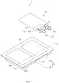
- FIG. 1 is an assembled view of a pouch type secondary battery 1 according to an embodiment of the present invention.
- the pouch type secondary battery 1 includes an electrode assembly 10, in which electrodes such as a positive electrode and a negative electrode and separators are stacked, and a pouch type battery case 13 accommodating the electrode assembly 10 therein.
- the pouch type secondary battery 1 To manufacture the pouch type secondary battery 1, first, slurry in which an electrode active material, a binder, and a plasticizer are mixed with each other is applied to a positive electrode collector and a negative electrode collector to manufacture electrodes such as a positive electrode and a negative electrode. The electrodes are stacked on both sides of the separator to manufacture the electrode assembly 10 having a predetermined shape. Then, the battery case 13 is sealed after the electrode assembly 10 is inserted into the battery case 13, and an electrolyte is injected into the battery case 13.
- the electrode assembly 10 may be a stacked structure including two types of electrodes such as a positive electrode and a negative electrode and a separator disposed between the electrodes to insulate the electrodes from each other or disposed at a left or right side of one electrode.
- the stacked structure may have various shapes without being limited in shape.
- the cathode and the anode each of which has a predetermined standard, may be stacked with the separator therebetween, or the stacked structure may be wound in the form of a jelly roll.
- Each of the two types of electrodes, i.e., the positive electrode and the negative electrode has a structure in which active material slurry is applied to the electrode collector having a metal foil or metal mesh shape.
- the slurry may be usually formed by agitating a granular active material, an auxiliary conductor, a binder, and a plasticizer with a solvent added. The solvent may be removed in the subsequent process.
- the electrode assembly 10 includes the electrode tabs 11.
- the electrode tabs 11 are respectively connected to a positive electrode and a negative electrode of the electrode assembly 10 to protrude to the outside of the electrode assembly 10, thereby providing a path, through which electrons are moved, between the inside and outside of the electrode assembly 10.
- a collector of the electrode assembly 10 is constituted by a portion coated with an electrode active material and a distal end, on which the electrode active material is not applied, i.e., a non-coating portion.
- each of the electrode tabs 11 may be formed by cutting the non-coating portion or by connecting a separate conductive member to the non-coating portion through ultrasonic welding.
- the electrode tabs 11 may protrude from one side of the electrode assembly 10 in the same direction, but the present invention is not limited thereto.
- the electrode tabs 11 may protrude in directions different from each other.
- the electrode lead 12 is connected to the electrode tab 11 through spot welding. Also, a portion of the electrode lead 12 is surrounded by an insulation part 14.
- the insulation part 14 may be disposed to be limited within a sealing part 134, on which a first case 131 and a second case 132 of the battery case 13 are thermally fused, so that the electrode lead 12 is bonded to the battery case 13. Also, electricity generated from the electrode assembly 10 may be prevented from flowing to the battery case 13 through the electrode lead 12, and the sealing of the battery case 13 may be maintained.
- the insulation part 14 may be made of a nonconductor having non-conductivity, which is not electrically conductive.
- the present invention is not limited thereto.
- various members may be used as the insulation part 14 as long as the members are capable of insulating the electrode lead 12.
- the electrode lead 12 includes a positive electrode lead 121 having one end connected to a positive electrode tab 111 to extend in a direction in which the positive electrode tab 111 protrudes and a negative electrode lead 122 having one end connected to a negative electrode tab 112 to extend in a direction in which the negative electrode tab 112 protrudes.
- a positive electrode lead 121 having one end connected to a positive electrode tab 111 to extend in a direction in which the positive electrode tab 111 protrudes
- a negative electrode lead 122 having one end connected to a negative electrode tab 112 to extend in a direction in which the negative electrode tab 112 protrudes.
- all of the other ends of the positive electrode lead 121 and the negative electrode lead 122 protrude to the outside of the battery case 13.
- electricity generated in the electrode assembly 10 may be supplied to the outside.
- each of the positive electrode tab 111 and the negative electrode tab 112 is formed to protrude in various directions, each of the positive electrode lead 121 and the negative electrode lead 122 may extend in various directions.
- the positive electrode lead 121 and the negative electrode lead 122 may be made of materials different from each other. That is, the cathode lead 121 may be made of the same material as the cathode collector, i.e., an aluminum (Al) material, and the anode lead 122 may be made of the same material as the anode collector, i.e., a copper (Cu) material or a copper material coated with nickel (Ni). Also, a portion of the electrode lead 12, which protrudes to the outside of the battery case 13, may be provided as a terminal part and electrically connected to an external terminal.
- Al aluminum
- the anode lead 122 may be made of the same material as the anode collector, i.e., a copper (Cu) material or a copper material coated with nickel (Ni).
- a portion of the electrode lead 12, which protrudes to the outside of the battery case 13 may be provided as a terminal part and electrically connected to an external terminal.
- the battery case 13 is a pouch made of a flexible material.
- the case in which the battery case 13 is the pouch will be described.
- a pouch film having flexibility is drawn by using a punch or the like, a portion of the pouch film is stretched to form a cup part 133 including a pocket-shaped accommodation space 1333, thereby manufacturing the battery case 13.
- the battery case 13 accommodates the electrode assembly 10 so that a portion of the electrode lead 12, i.e., the terminal part is exposed and then is sealed.
- the battery case 13 includes a first case 131 and a second case 132.
- the accommodation space 1333 formed in each of the cup parts 133 to accommodate the electrode assembly 10 may be provided in the first case 131 and the second case 132.
- the battery case 13 When the electrode assembly 10 is accommodated in the accommodation space 1333, the battery case 13 is folded so that the first case 131 and the second case 132 face each other. Also, the sealing part 134 is sealed so that the electrode assembly 10 is not separated to the outside of the battery case 13, thereby sealing the accommodation space 1333.
- a bridge 136 is a portion that is not molded between the two cup parts 133 when drawing and molding the two cup parts 133 so as to be adjacent to each other in the pouch film.
- the bridge 136 is formed between the two cup parts 133 and has a constant width w (see FIG. 2 ) and a constant height.
- the outer walls bent from both ends of the bridge 136 are unfolded. Detailed description of the bridge 136 will be described later.
- the electrode assembly 10 When the electrode lead 12 is connected to the electrode tab 11 of the electrode assembly 10, and the insulation part 14 is formed in a portion of the electrode lead 12, the electrode assembly 10 is accommodated in the accommodation space 1333 provided in one cup part 133 of the first case 131 and the second case 132, and the remaining case of the first case 131 and the second case 132 covers the accommodation space 1333. Also, the electrolyte is injected into the accommodation space, and the sealing part 134 formed on edges of the first case 131 and the second case 132 is sealed. The electrolyte may move lithium ions generated by electrochemical reaction of the electrode during charging and discharging of the secondary battery 1.
- the electrolyte may include a non-aqueous organic electrolyte that is a mixture of a lithium salt and a high-purity organic solvent or a polymer using a polymer electrolyte.
- the pouch type secondary battery 1 may be manufactured through the above-described method.
- FIG. 2 is a cross-sectional view of the battery case 13, taken along line A-A' according to an embodiment of the present invention.
- the sealing part 134 since the two cup parts 133 are different depths, and the sealing part 134 is folded toward the cup part 133 having the deeper depth, even if a length of the sealing part 134 is long, it may prevent the cup parts 133 from more protruding outward from a bottom portion. Also, since the bottom portions of the cup parts 133 are inclined toward the bridge 136, the outer wall formed at an opposite side of the bridge 136 may be formed to be higher so that the secondary battery 1 increases in capacity. Also, since the sealing part 134 is double-folded, there is unnecessary to excessively stretch the outer wall of the cup part 133 formed toward the opposite side of the bridge 136.
- the bottom portions of the two cup parts 133 may be formed parallel to each other.
- a bat ear may be reduced in size to reduce the error occurring in the designed size of the secondary battery, and the secondary batteries may be easily assembled to manufacture the battery module.
- the pouch type battery case 13 configured to accommodate the electrode assembly 10, in which the electrodes and the separators are stacked, according to an embodiment of the present invention includes: a first cup part 1331 and a second cup part 1332, which are arranged parallel to a pouch film and formed to be recessed; and a bridge 136 formed between the first cup part 1331 and the second cup part 1332 and having a constant width w and height.
- the first cup part 1331 includes: a first outer wall 1371 formed toward an opposite to the bridge 136; a second outer wall 1372 formed toward the bridge 136; and a first bottom portion 1381 configured to connect the first outer wall 1371 to the second outer wall 1372
- the second cup part 1332 includes: a third outer wall 1373 formed toward the bridge 136; a fourth outer wall 1374 formed toward the opposite to the bridge 136; and a second bottom portion 1382 configured to connect the third outer wall 1373 to the fourth outer wall 1374.
- At least one of the first bottom portion 1381 or the second bottom portion 1382 is inclined toward the bridge 136, and the fourth outer wall 1374 has a height greater than that of the first outer wall 1371.
- the electrode 10 is thicker.
- a depth of the cup part 133 needs to further increase.
- cracks occur at the edges, and whitening occurs around the cracks. As a result, there is a limit to the depth of the cup part 133.
- the drawing-molding is performed on the pouch film to manufacture the battery case 13 including two cup parts 133 such as the first and second cup parts 1331 and 1332. That is, the first cup part 1331 is formed in the first case 131, and the second cup part 1332 is formed in the second case 132. Also, as illustrated in FIG. 2 , the first cup part 1331 includes the first outer wall 1371 formed toward the opposite side of the bridge 136, the second outer wall 1372 formed toward the bridge 136, and the first bottom portion 1381 connecting the first outer wall 1371 to the second outer wall 1372. In addition, the second cup part 1332 includes the third outer wall 1373 formed toward the bridge 136, the fourth outer wall 1374 formed toward the opposite side of the bridge 136, and the second bottom portion 1382 connecting the third outer wall 1373 to the fourth outer wall 1374.
- the first cup part 1331 and the second cup part 1332 are molded side by side on the pouch film to manufacture the battery case 13, and then a portion between the first cup part 1331 and the second cup part 1332 is folded. Accordingly, the first cup part 1331 and the second cup part 1332 may accommodate the electrode assembly 10 from above and below.
- the sealing part 134 may more protrude from the bottom portion even if folded in any one direction of the first cup part 1331 and the second cup part 1332 because the sealing part 134 has a long length.
- the first cup part 1331 and the second cup part 1332 have different depths as a whole.
- the second cup part 1332 has a length greater than that the first cup part 1331 as a whole.
- a height d of the fourth outer wall 1374 is greater than a height a of the first outer wall 1371.
- a height c of the third outer wall 1373 is greater than a height b of the second outer wall 1372.
- the sealing part 134 is folded toward the second cup part 1332 having the deeper depth, in particular, the fourth outer wall 1374.
- the bridge 136 having a constant width w and height is formed between the first cup part 1331 and the second cup part 1332. It is preferable that the width w of the bridge 136 is 0.2 cm to 6 cm. In general, in the case of the small secondary battery 1, the width w of the bridge 136 may be 0.2 cm to 0.7 cm, and in the case of the medium and large secondary battery 1, the width w of the bridge 136 may be 1 cm to 6 cm. If the width w of the bridge 136 is less than 0.2 cm, there is a problem that cracks occur in the bridge 136 when the two cup parts 133 are molded. In addition, if the width w of the bridge 136 is greater than 6 cm, when the battery case 13 is folded to manufacture the secondary battery 1, a large unnecessary space is occupied to deteriorate energy efficiency to volume.
- each of the second outer wall 1372 and the third outer wall 1372 has a relatively short stretchable length when compared to the first outer wall 1371 and the fourth outer wall 1374.
- each of a first bottom portion 1381 and a second bottom portion 1382 have an inclination toward the bridge 136.
- the height a of the first outer wall 1371 is greater than the height b of the second outer wall 1372
- the height d of the fourth outer wall 1374 is greater than the height c of the third outer wall 1373. That is, it is preferable that each of the outer walls formed toward the opposite side of the bridge 136 has a height greater than that of each of the outer walls formed toward the bridge 136.
- the heights a and d of the first outer wall 1371 and the fourth outer wall 1374 having relatively long stretchable lengths may increase, and thus the accommodation space 1333 may increase in volume, and secondary battery 1 may increase in capacity.
- the present invention is not limited thereto, and only one of the first bottom portion 1381 and the second bottom portion 1382 may have the inclination.
- the heights b and c of the second outer wall 1372 and the third outer wall 1373 increase, an amount of stretchiness may increase with respect to the bridge 136. Therefore, when the secondary battery 1 is manufactured, a portion of the folded edge may protrude to form a bat ear.
- the heights b and c of the second outer wall 1372 and the third outer wall 1373 are relatively less stretchable.
- the stretched amount is not large with respect to the width w of the bridge 136, a size of the bat ear may be reduced to reduce an error occurring in the designed size of the secondary battery 1, and the secondary batteries 1 may be easily assembled to form the battery module or the like.
- FIG. 3 is a cross-sectional view illustrating a configuration in which the battery case of FIG. 2 is being folded
- FIG. 4 is a cross-sectional view illustrating a configuration in which the folding of the battery case of FIG. 2 is completed.
- the second outer wall 1372 and the third outer wall 1373 are bent from both ends of the bridge 136, respectively. Then, the electrode assembly 10 is accommodated in the accommodation space 1333 of the cup part 133 formed in the battery case 13, and the battery case 13 is folded. Then, as illustrated in FIG. 3 , a portion between the second outer wall 1372 and the bridge 136 and a portion between the third outer wall 1373 and the bridge 136 are unfolded.
- the first cup part 1331 and the second cup part 1332 completely surround and accommodate the electrode assembly 10. Also, the sealing part 134 extending outward from a periphery of the first cup part 1331 and the sealing part 134 extending outward from a periphery of the second cup part 1332 face each other to contact each other.
- an inclination formed by the first bottom portion 1381 toward the bridge 136 and an inclination formed by the second bottom portion 1382 toward the bridge 136 may be different from each other.
- the first bottom portion 1381 and the second bottom portion 1382 are substantially parallel to each other.
- the secondary battery 1 may have a stable shape to stably accommodate the electrode assembly 10.
- the term 'substantially parallel to each other' means not only a case of being completely parallel to each other but also a case of being close to being parallel so as to enough to stably accommodate the electrode assembly 10.
- an inclination angle ⁇ 1 of the inclination formed by the first bottom portion 1381 (see FIG. 2 ) and an inclination angle ⁇ 2 formed by the second bottom portion 1382 (see FIG. 2 ) have to be equal or similar to each other.
- a ratio of the sum of the height a of the first outer wall 1371 and the height d of the fourth outer wall 1374 to the sum of the height b of the second outer wall 1372, the width w of the bridge 136, and the height c of the third outer wall 1373 may be preferably 0.95 to 1.05, and in particularly, the ratio may be 0.99 to 1.01. If the ratio is less than 0.95 or greater than 1.05, since the first bottom portion 1381 and the second bottom portion 1382 are not parallel to each other, the secondary battery 1 may have an unstable shape.
- the portion between the second outer wall 1372 and the bridge 136 and the portion between the third outer wall 1373 and the bridge 136 may not be completely unfolded, and thus the bent shape may remain to some extent.
- the portion between the second outer wall 1372 and the bridge 136 and the portion between the third outer wall 1373 and the bridge 136 may be unfolded to be completely flat.
- the second outer wall 1372, the bridge 136, and the third outer wall 1373 may exist on one plane.
- the bent and then unfolded trace may remain the boundaries between the second outer wall 1372 and the bridge 136 and between the third outer wall 1373 and the bridge 136.
- a swell may be finely formed on the surface of the battery case, or wrinkles may be formed, and thus, the trace may remain on the boundaries.
- the second outer wall 1372, the bridge 136, and the third outer wall 1373 may be specified based on the trace.
- FIG. 5 is a cross-sectional view illustrating a configuration in which the folding of the sealing part 134 of the battery case 13 of FIG. 2 is completed.
- the sealing part 134 of the first cup part 1331 and the sealing part 134 of the second cup part 1332 face each other to contact each other. Also, heat and a pressure may be applied to the sealing part 134 to seal the sealing part, thereby sealing the inside of the secondary battery 1.
- the sealing part 134 is long to some extent. However, if the sealing part 134 is left as it is, it is preferable to fold the sealing part 134 because an unnecessary space is occupied when the secondary battery 1 is manufactured.
- the sealing part 134 when the sealing part 134 is folded, the sealing part 134 may be folded toward the second cup part 1332 having the deeper depth, particularly, the fourth outer wall 1374.
- a length of the folded sealing part 134 is less than the height of the fourth outer wall 1374 of the second cup part 1332.
- the sealing unit 134 is double-folded, that is, folded two or more times in succession, as illustrated in FIG. 5 . Therefore, even if the length of the sealing part 134 is significantly long, it is not necessary to excessively stretch the outer wall of the cup part 133 formed toward the opposite side of the bridge 136, particularly, the fourth outer wall 1374.
Applications Claiming Priority (2)
| Application Number | Priority Date | Filing Date | Title |
|---|---|---|---|
| KR1020190106157A KR20210025995A (ko) | 2019-08-28 | 2019-08-28 | 파우치 형 전지 케이스 및 파우치 형 이차 전지 |
| PCT/IB2020/059961 WO2021038545A1 (ko) | 2019-08-28 | 2020-10-23 | 파우치 형 전지 케이스 및 파우치 형 이차 전지 |
Publications (2)
| Publication Number | Publication Date |
|---|---|
| EP3993143A1 true EP3993143A1 (de) | 2022-05-04 |
| EP3993143A4 EP3993143A4 (de) | 2022-11-09 |
Family
ID=74684987
Family Applications (1)
| Application Number | Title | Priority Date | Filing Date |
|---|---|---|---|
| EP20859168.5A Pending EP3993143A4 (de) | 2019-08-28 | 2020-10-23 | Beutelartiges batteriegehäuse und beutelartige sekundärbatterie |
Country Status (4)
| Country | Link |
|---|---|
| US (1) | US20230071692A1 (de) |
| EP (1) | EP3993143A4 (de) |
| KR (1) | KR20210025995A (de) |
| WO (1) | WO2021038545A1 (de) |
Families Citing this family (3)
| Publication number | Priority date | Publication date | Assignee | Title |
|---|---|---|---|---|
| KR20210064670A (ko) * | 2019-11-26 | 2021-06-03 | 주식회사 엘지에너지솔루션 | 파우치형 케이스 성형장치 및 이를 이용한 파우치형 케이스의 제조방법 |
| KR102578784B1 (ko) * | 2019-12-17 | 2023-09-15 | 주식회사 엘지에너지솔루션 | 이차전지용 케이스 및 이차전지 |
| KR102566013B1 (ko) * | 2021-03-30 | 2023-08-10 | 주식회사 엘지에너지솔루션 | 파우치형 이차전지 및 이를 포함하는 전지 모듈 |
Family Cites Families (8)
| Publication number | Priority date | Publication date | Assignee | Title |
|---|---|---|---|---|
| JP2006324143A (ja) * | 2005-05-19 | 2006-11-30 | Nissan Motor Co Ltd | 二次電池 |
| KR101446150B1 (ko) * | 2010-07-16 | 2014-10-01 | 주식회사 엘지화학 | 파우치형 이차 전지 및 이를 제조하는 방법 |
| CN103066218B (zh) * | 2011-10-24 | 2016-01-20 | 索尼电子(无锡)有限公司 | 电池、电池芯容器形成方法以及电子设备 |
| KR102023554B1 (ko) * | 2015-08-19 | 2019-09-24 | 주식회사 엘지화학 | 이차 전지용 파우치 |
| KR20170088024A (ko) | 2016-01-22 | 2017-08-01 | 주식회사 엘지화학 | 절곡 실링부와 전극조립체 수납부가 높이 차이를 가진 파우치형 전지셀 |
| KR102064460B1 (ko) * | 2016-09-12 | 2020-01-10 | 주식회사 엘지화학 | 이차전지용 파우치 외장재, 이를 이용한 파우치형 이차전지 및 그 제조 방법 |
| KR102368727B1 (ko) * | 2018-01-24 | 2022-02-28 | 주식회사 엘지에너지솔루션 | 이차전지용 파우치 및 그 이차전지용 파우치를 성형하기 위한 금형 다이 |
| KR102268404B1 (ko) * | 2018-01-31 | 2021-06-24 | 주식회사 엘지에너지솔루션 | 이차전지 제조방법, 이차전지용 파우치 제조방법 및 이차전지용 파우치 |
-
2019
- 2019-08-28 KR KR1020190106157A patent/KR20210025995A/ko active Search and Examination
-
2020
- 2020-10-23 WO PCT/IB2020/059961 patent/WO2021038545A1/ko unknown
- 2020-10-23 US US17/635,551 patent/US20230071692A1/en active Pending
- 2020-10-23 EP EP20859168.5A patent/EP3993143A4/de active Pending
Also Published As
| Publication number | Publication date |
|---|---|
| KR20210025995A (ko) | 2021-03-10 |
| WO2021038545A1 (ko) | 2021-03-04 |
| US20230071692A1 (en) | 2023-03-09 |
| EP3993143A4 (de) | 2022-11-09 |
Similar Documents
| Publication | Publication Date | Title |
|---|---|---|
| EP3916830A1 (de) | Sekundärbatterie, gehäuse und pouch-sekundärbatterie | |
| EP3993143A1 (de) | Beutelartiges batteriegehäuse und beutelartige sekundärbatterie | |
| EP4057438A1 (de) | Biegevorrichtung und -verfahren für elektrodenzungen | |
| US11387516B2 (en) | Battery module | |
| US11817559B2 (en) | Apparatus and method for manufacturing secondary battery | |
| KR20210011813A (ko) | 이차 전지용 전지 케이스 및 파우치 형 이차 전지 | |
| US20220029192A1 (en) | Apparatus and Method for Manufacturing Secondary Battery | |
| JP2003007346A (ja) | リチウム二次電池及びその製造方法 | |
| EP3754749B1 (de) | Sekundärbatterie und batteriemodul | |
| KR20210076770A (ko) | 이차 전지용 전지 케이스 및 파우치 형 이차 전지 | |
| EP3958343A1 (de) | Batteriegehäuse für sekundärbatterie und sekundärbeutelbatterie | |
| US11394093B2 (en) | Secondary battery and battery module | |
| KR20210002995A (ko) | 이차 전지용 전지 케이스 및 파우치 형 이차 전지 | |
| EP4106098A1 (de) | Sekundärbatterie und batteriemodul | |
| EP4044354A1 (de) | Sekundärbatterie | |
| KR20210037460A (ko) | 이차 전지용 전지 케이스 및 그의 제조 방법 | |
| KR20210098756A (ko) | 이차 전지용 전지 케이스 및 이차 전지 | |
| KR100686845B1 (ko) | 파우치형 리튬 이차전지 |
Legal Events
| Date | Code | Title | Description |
|---|---|---|---|
| STAA | Information on the status of an ep patent application or granted ep patent |
Free format text: STATUS: THE INTERNATIONAL PUBLICATION HAS BEEN MADE |
|
| PUAI | Public reference made under article 153(3) epc to a published international application that has entered the european phase |
Free format text: ORIGINAL CODE: 0009012 |
|
| STAA | Information on the status of an ep patent application or granted ep patent |
Free format text: STATUS: REQUEST FOR EXAMINATION WAS MADE |
|
| 17P | Request for examination filed |
Effective date: 20220127 |
|
| AK | Designated contracting states |
Kind code of ref document: A1 Designated state(s): AL AT BE BG CH CY CZ DE DK EE ES FI FR GB GR HR HU IE IS IT LI LT LU LV MC MK MT NL NO PL PT RO RS SE SI SK SM TR |
|
| XX | Miscellaneous (additional remarks) |
Free format text: THE FILING DATE OF THE INTERNATIONAL APPLICATION IS WITHIN TWO MONTHS FROM THE DATE OF EXPIRATION OF THE PRIORITY PERIOD (R. 26BIS.3 PCT). |
|
| REG | Reference to a national code |
Ref country code: DE Ref legal event code: R079 Free format text: PREVIOUS MAIN CLASS: H01M0050100000 Ipc: H01M0050105000 |
|
| A4 | Supplementary search report drawn up and despatched |
Effective date: 20221010 |
|
| RIC1 | Information provided on ipc code assigned before grant |
Ipc: H01M 10/04 20060101ALI20221004BHEP Ipc: H01M 50/124 20210101ALI20221004BHEP Ipc: H01M 50/105 20210101AFI20221004BHEP |
|
| DAV | Request for validation of the european patent (deleted) | ||
| DAX | Request for extension of the european patent (deleted) |