EP3993086B1 - Electrode for secondary battery and method for manufacturing the same - Google Patents
Electrode for secondary battery and method for manufacturing the same Download PDFInfo
- Publication number
- EP3993086B1 EP3993086B1 EP20847879.2A EP20847879A EP3993086B1 EP 3993086 B1 EP3993086 B1 EP 3993086B1 EP 20847879 A EP20847879 A EP 20847879A EP 3993086 B1 EP3993086 B1 EP 3993086B1
- Authority
- EP
- European Patent Office
- Prior art keywords
- electrode
- cutting
- line
- cutting step
- cutting line
- Prior art date
- Legal status (The legal status is an assumption and is not a legal conclusion. Google has not performed a legal analysis and makes no representation as to the accuracy of the status listed.)
- Active
Links
Images


Classifications
-
- H—ELECTRICITY
- H01—ELECTRIC ELEMENTS
- H01M—PROCESSES OR MEANS, e.g. BATTERIES, FOR THE DIRECT CONVERSION OF CHEMICAL ENERGY INTO ELECTRICAL ENERGY
- H01M4/00—Electrodes
- H01M4/02—Electrodes composed of, or comprising, active material
- H01M4/04—Processes of manufacture in general
-
- H—ELECTRICITY
- H01—ELECTRIC ELEMENTS
- H01M—PROCESSES OR MEANS, e.g. BATTERIES, FOR THE DIRECT CONVERSION OF CHEMICAL ENERGY INTO ELECTRICAL ENERGY
- H01M50/00—Constructional details or processes of manufacture of the non-active parts of electrochemical cells other than fuel cells, e.g. hybrid cells
- H01M50/50—Current conducting connections for cells or batteries
- H01M50/531—Electrode connections inside a battery casing
- H01M50/533—Electrode connections inside a battery casing characterised by the shape of the leads or tabs
-
- B—PERFORMING OPERATIONS; TRANSPORTING
- B23—MACHINE TOOLS; METAL-WORKING NOT OTHERWISE PROVIDED FOR
- B23D—PLANING; SLOTTING; SHEARING; BROACHING; SAWING; FILING; SCRAPING; LIKE OPERATIONS FOR WORKING METAL BY REMOVING MATERIAL, NOT OTHERWISE PROVIDED FOR
- B23D79/00—Methods, machines, or devices not covered elsewhere, for working metal by removal of material
-
- H—ELECTRICITY
- H01—ELECTRIC ELEMENTS
- H01M—PROCESSES OR MEANS, e.g. BATTERIES, FOR THE DIRECT CONVERSION OF CHEMICAL ENERGY INTO ELECTRICAL ENERGY
- H01M4/00—Electrodes
- H01M4/02—Electrodes composed of, or comprising, active material
-
- H—ELECTRICITY
- H01—ELECTRIC ELEMENTS
- H01M—PROCESSES OR MEANS, e.g. BATTERIES, FOR THE DIRECT CONVERSION OF CHEMICAL ENERGY INTO ELECTRICAL ENERGY
- H01M50/00—Constructional details or processes of manufacture of the non-active parts of electrochemical cells other than fuel cells, e.g. hybrid cells
- H01M50/50—Current conducting connections for cells or batteries
- H01M50/531—Electrode connections inside a battery casing
-
- H—ELECTRICITY
- H01—ELECTRIC ELEMENTS
- H01M—PROCESSES OR MEANS, e.g. BATTERIES, FOR THE DIRECT CONVERSION OF CHEMICAL ENERGY INTO ELECTRICAL ENERGY
- H01M50/00—Constructional details or processes of manufacture of the non-active parts of electrochemical cells other than fuel cells, e.g. hybrid cells
- H01M50/50—Current conducting connections for cells or batteries
- H01M50/531—Electrode connections inside a battery casing
- H01M50/534—Electrode connections inside a battery casing characterised by the material of the leads or tabs
-
- H—ELECTRICITY
- H01—ELECTRIC ELEMENTS
- H01M—PROCESSES OR MEANS, e.g. BATTERIES, FOR THE DIRECT CONVERSION OF CHEMICAL ENERGY INTO ELECTRICAL ENERGY
- H01M4/00—Electrodes
- H01M4/02—Electrodes composed of, or comprising, active material
- H01M2004/021—Physical characteristics, e.g. porosity, surface area
-
- Y—GENERAL TAGGING OF NEW TECHNOLOGICAL DEVELOPMENTS; GENERAL TAGGING OF CROSS-SECTIONAL TECHNOLOGIES SPANNING OVER SEVERAL SECTIONS OF THE IPC; TECHNICAL SUBJECTS COVERED BY FORMER USPC CROSS-REFERENCE ART COLLECTIONS [XRACs] AND DIGESTS
- Y02—TECHNOLOGIES OR APPLICATIONS FOR MITIGATION OR ADAPTATION AGAINST CLIMATE CHANGE
- Y02E—REDUCTION OF GREENHOUSE GAS [GHG] EMISSIONS, RELATED TO ENERGY GENERATION, TRANSMISSION OR DISTRIBUTION
- Y02E60/00—Enabling technologies; Technologies with a potential or indirect contribution to GHG emissions mitigation
- Y02E60/10—Energy storage using batteries
-
- Y—GENERAL TAGGING OF NEW TECHNOLOGICAL DEVELOPMENTS; GENERAL TAGGING OF CROSS-SECTIONAL TECHNOLOGIES SPANNING OVER SEVERAL SECTIONS OF THE IPC; TECHNICAL SUBJECTS COVERED BY FORMER USPC CROSS-REFERENCE ART COLLECTIONS [XRACs] AND DIGESTS
- Y02—TECHNOLOGIES OR APPLICATIONS FOR MITIGATION OR ADAPTATION AGAINST CLIMATE CHANGE
- Y02P—CLIMATE CHANGE MITIGATION TECHNOLOGIES IN THE PRODUCTION OR PROCESSING OF GOODS
- Y02P70/00—Climate change mitigation technologies in the production process for final industrial or consumer products
- Y02P70/50—Manufacturing or production processes characterised by the final manufactured product
Definitions
- the present invention relates to an electrode for a secondary battery and a method for manufacturing the same, and more particularly, to an electrode for a secondary battery having an atypical shape and a method for manufacturing the electrode.
- a secondary battery that is repetitively chargeable and dischargeable has a regular shape such as a rectangular parallelepiped shape, a cylindrical shape, and the like.
- a regular shape such as a rectangular parallelepiped shape, a cylindrical shape, and the like.
- the shape of the secondary battery mounted inside the electronic device is also required to be atypical, unlike the related art.
- an electrode assembly having an atypical shape is manufactured and is accommodated in an exterior such as a pouch type exterior, and then, the exterior is sealed to manufacture the secondary battery.
- US 2014/255755 discloses a method for manufacturing an electrode, the method comprising: a first cutting step of cutting a portion of an electrode sheet along a first cutting line comprising a closed curve to form an electrode having a shape corresponding to the closed curve of the first cutting line; and a second cutting step of additionally cutting a portion of the electrode sheet along a second cutting line comprising a closed curve to form an electrode having a shape corresponding to the closed curve of the second cutting line, which is separated from the electrode formed in the first cutting step, after the first cutting step, wherein the first cutting line and the second cutting line cross each other to form a crossing area on the electrode sheet.
- EP 3 340 358 discloses an electrode for a secondary battery, the electrode comprising: a first body part having a first width and extending by a first length in a first direction; and a second body part having a second width less than the first length and extending from one end of the first body part by a second length in a second direction.
- an object of the prevent invention for solving the above problem is to solve the problem of damage of the electrode in a process of manufacturing a secondary battery having an atypical shape.
- an electrode for a secondary battery is defined in the appended claims.
- the problem of damage of the electrode, which occurs in the process of manufacturing the secondary battery having the atypical shape may be solved.
- FIG. 1 is a plan view illustrating a first cutting line formed on an electrode sheet by a first cutting step in a method for manufacturing an electrode according to the present invention
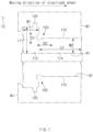
- FIG. 2 is a plan view illustrating a second cutting line formed on the electrode sheet by a second cutting step in the method for manufacturing the electrode according to the present invention.
- a method for manufacturing an electrode according to the present invention comprises a first cutting step of cutting a portion of an electrode sheet 10 to form an electrode 100.
- the electrode sheet 10 is cut along a first cutting line N1.
- the first cutting line N1 is illustrated as a dash-single dotted line.
- the first cutting line N1 comprises a closed curve.
- the electrode 100 has a shape corresponding to the closed curve provided in the first cutting line N1.
- FIG. 1 illustrates a case in which two electrodes are formed symmetrical to each other on the electrode sheet 10 by the first cutting step.
- the method for manufacturing the electrode according to the present invention further comprises a second cutting step which is performed after the first cutting step and in which a portion of the electrode sheet 10 is additionally cut to form an electrode that is separated from the electrode formed in the first cutting step.
- the electrode sheet 10 is cut along a second cutting line N2.
- the first cutting line N1 formed in the first cutting step is illustrated as the dash-single dotted line
- the second cutting line N2 formed in the second cutting step is illustrated as a dash-double dotted line.
- the second cutting line N2 comprises a closed curve. Even in the second cutting step, the electrode 100 has a shape corresponding to the closed curve provided in the second cutting line N2.
- each of the first cutting line N1 and the second cutting line N2 may comprise a plurality of closed curves. That is, according to the present invention, a plurality of electrodes 100 may be formed in each of the first cutting step and the second cutting step.
- FIGS. 1 and 2 illustrate a case in which two electrodes are formed symmetrical to each other on the electrode sheet 10 in each of the first cutting step and the second cutting step.
- the second cutting step is performed after the first cutting step is performed on the electrode sheet 10, and the electrode sheet 10 moves in one direction.
- a mold (not shown) for cutting the electrode sheet 10 in the first cutting step and a mold for cutting the electrode sheet 10 in the second cutting step may be the same.
- the overall shape of the first cutting line N1 and the overall shape of the second cutting line N2 may be the same.
- the shape of the electrode formed in the first cutting step and the shape of the electrode formed in the second cutting step may also be the same.
- the electrode 100 formed in each of the first cutting step and the second cutting step may comprise a body part 110 forming a body of the electrode and an electrode tab 120 protruding from the body part 110 in one direction.
- the body part 110 comprises a first body part 112 having a first width W1 and extending by a first length L1 in a first direction D1 and a second body part 114 having a second width W2 less than the first length L1 and extending from one end of the first body part 112 by a second length L2 in a second direction D2.
- the body part 110 has an L-shape as illustrated in FIGS. 1 and 2 .
- the first direction D1 and the second direction D2 may be perpendicular to each other.
- FIGS. 1 and 2 illustrate a state in which, in the two electrodes 100 respectively formed in the first cutting step and the second cutting step, the electrode tab 120 of the electrode 100 formed on an upper portion of the electrode sheet 10 protrudes upward, and the electrode tab 120 of the electrode 100 formed on a lower portion of the electrode sheet 10 protrudes downward.
- the first cutting line N1 and the second cutting line N2 may overlap each other on a portion of the areas.
- the electrode formed in the first cutting step and the electrode formed in the second cutting step may be in contact with each other by using an area, on which the first cutting line N1 and the second cutting line N2 overlap each other, as a boundary.
- the boundary between the electrode formed by the first cutting line N1 and the electrode formed by the second cutting line N2 is illustrated as the dash-double dotted line, this is merely illustrated as the dash-single dotted line for convenience, and actually may be an area on which the first cutting line N1 and the second cutting line N2 overlap each other.
- the first cutting line N1 and the second cutting line N2 that are respectively formed in the first cutting step and the second cutting step cross each other.
- crossing areas C1, C2, and C3 that are areas on which the first cutting line N1 and the second cutting line N2 cross each other may be formed on the electrode sheet 10.
- the crossing areas may be formed in plurality.
- FIG. 2 illustrates a case in which total six crossing area are formed.
- two crossing areas formed at positions symmetrical to each other will be denoted by the same reference numeral.
- the crossing areas may be formed on one end, which is adjacent to the electrode formed in the first cutting step, of both ends of the second body part 114 of the electrode formed in the second cutting step in a direction of the second length L2 (i.e., a right end of the second body part of the electrode formed in the second cutting step).
- the crossing area formed on one end, which is adjacent to the electrode formed in the first cutting step, of both the ends of the second body part 114 of the electrode formed in the second cutting step in the direction of the second length L2 is indicated by a reference symbol C1.
- the term 'crossing area' means a crossing area indicated by the reference symbol C1.
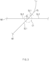
- FIG. 3 is an enlarged plan view illustrating one of the crossing areas of the first cutting line and the second cutting line in the method for manufacturing the electrode according to the present invention.
- the first cutting line N1 formed in the first cutting step and the second cutting line N2 formed in the second cutting step cross each other to form a crossing area C1 on the electrode sheet.
- the first cutting line N1 and the second cutting line N2 cross each other in a straight line on the crossing area C1.
- a straight line of the first cutting line N1, which is formed on the crossing area C1 will be indicated by a reference symbol SL1
- a straight line of the second cutting line N2, which is formed on the crossing area C1 will be indicated by a reference symbol SL2.
- one end of the straight line SL1 of the first cutting line N1, which is formed on the crossing area C1 is connected to a curved line CL constituting the first cutting line N1, and the straight line SL1 is connected to the curved line CL by a tangent line. That is, according to the present invention, an inclination of the straight line SL1 of the first cutting line N1, which is formed on the crossing area C1, and a tangent inclination of the curved line CL at a point at which the curved line CL and the straight line SL1 meet each other may be the same.
- FIG. 4 is an enlarged plan view illustrating a crossing area of a first cutting line and a second cutting line in a method for manufacturing an electrode according to a comparative example.
- a first cutting line N1' is formed in a curved shape with a point of inflection on an area on which a first cutting line N1' and a second cutting line N2' cross each other according to a comparative example.
- the inclination of the first cutting line N1' and the inclination of the second cutting line N2' are the same at the point of the inflection, when the point at which the first cutting line N1' and the second cutting line N2' cross each other is the point of the inflection, i.e., referring to FIG. 4 , when the second cutting line N2' is formed along a solid line, an electrode having a smooth corner may be manufactured.
- first cutting line N1' and the second cutting line N2' do not cross each other at the point of the inflection due to undesired movement of an electrode sheet or a mold, an electrode having an angular corner may be manufactured.
- an electrode having a sharp corner may be manufactured.
- the electrode when the inclination of the first cutting line N1' is significantly changed as the first cutting line N1' is gradually away from the point of the inflection, since a curved area having a recessed shape is formed around an corner formed on the area on which the first cutting line N1' and the second cutting line N2' cross each other (an inner area of a circle illustrated in FIG. 4 ), a sharper corner may be formed.
- the electrode may be damaged in a process of accommodating an electrode assembly comprising the electrode into an exterior.
- the electrode on which the corner having a uniform quality is formed may be manufactured.
- the area on which the first cutting line N1 and the second cutting line N2 cross each other is formed as the straight line, and also, the straight line SL1 of the first cutting line N1 is formed as the tangent line in the vicinity of the crossing area C1, a degree of sharpness of the corner of the electrode on the crossing area C1 may be remarkably improved compared to the comparative example to solve the problem of damage of the electrode.
- an angle ⁇ between the first cutting line N1 and the second cutting line N2 on the area, on which the electrode is formed, among angles formed by meeting the first cutting line N1 and the second cutting line N2 on the crossing area C1 may be an obtuse angle.
- the electrode 10 for the secondary battery may comprise a body part 110 and an electrode tab 120 protruding from the body part 110 in one direction.
- the body part 110 comprises a first body part 112 having a first width W1 and extending by a first length L1 in a first direction D1 and a second body part 114 having a second width W2 less than the first length L1 and extending from one end of the first body part 112 by a second length L2 in a second direction D2.
- the body part 110 has an L-shape as described above.
- an area on which two straight lines meet each other is formed on at least one of corners of one end of the second body part 114 in a direction of the second length L2, and one end of one straight line of the two straight lines is connected to a curved line.
- the one straight line is connected to the curved line by a tangent line.
- an angle ⁇ at which the two straight lines meet each other may be an obtuse angle.
Landscapes
- Chemical & Material Sciences (AREA)
- Chemical Kinetics & Catalysis (AREA)
- Electrochemistry (AREA)
- General Chemical & Material Sciences (AREA)
- Engineering & Computer Science (AREA)
- Manufacturing & Machinery (AREA)
- Physics & Mathematics (AREA)
- Optics & Photonics (AREA)
- Mechanical Engineering (AREA)
- Battery Electrode And Active Subsutance (AREA)
- Secondary Cells (AREA)
Description
- The present application claims the benefit of the priority of
Korean Patent Application No. 10-2019-0092474, filed on July 30, 2019 - The present invention relates to an electrode for a secondary battery and a method for manufacturing the same, and more particularly, to an electrode for a secondary battery having an atypical shape and a method for manufacturing the electrode.
- In general, a secondary battery that is repetitively chargeable and dischargeable has a regular shape such as a rectangular parallelepiped shape, a cylindrical shape, and the like. However, as electronic devices are diversified in shape, and the need to maximize utilization of an internal space of such an electronic device increases, the shape of the secondary battery mounted inside the electronic device is also required to be atypical, unlike the related art.
- In the case of the secondary battery having an atypical shape, generally, an electrode assembly having an atypical shape is manufactured and is accommodated in an exterior such as a pouch type exterior, and then, the exterior is sealed to manufacture the secondary battery.
- However, when the shape of an electrode constituting the electrode assembly is out of the desired shape, there has been a problem that the electrode is damaged while the electrode assembly is accommodated in the exterior. Particularly, in a process of cutting the electrode using a mold to manufacture the electrode having the atypical shape, if an electrode defect occurs on an area, on which the electrode is notched, due to undesirable movement of the mold or the electrode, the aforementioned problem of damage of the electrode frequently occurs.
-
US 2014/255755 discloses a method for manufacturing an electrode, the method comprising: a first cutting step of cutting a portion of an electrode sheet along a first cutting line comprising a closed curve to form an electrode having a shape corresponding to the closed curve of the first cutting line; and a second cutting step of additionally cutting a portion of the electrode sheet along a second cutting line comprising a closed curve to form an electrode having a shape corresponding to the closed curve of the second cutting line, which is separated from the electrode formed in the first cutting step, after the first cutting step, wherein the first cutting line and the second cutting line cross each other to form a crossing area on the electrode sheet. -
EP 3 340 358 discloses an electrode for a secondary battery, the electrode comprising: a first body part having a first width and extending by a first length in a first direction; and a second body part having a second width less than the first length and extending from one end of the first body part by a second length in a second direction. - Accordingly, an object of the prevent invention for solving the above problem is to solve the problem of damage of the electrode in a process of manufacturing a secondary battery having an atypical shape.
- According to an aspect of the present invention for achieving the above object, a method for manufacturing an electrode is defined in the appended claims.
- According to another aspect of the present invention for achieving the above object, an electrode for a secondary battery is defined in the appended claims.
- According to the present invention, the problem of damage of the electrode, which occurs in the process of manufacturing the secondary battery having the atypical shape, may be solved.
-
-
FIG. 1 is a plan view illustrating a first cutting line formed on an electrode sheet by a first cutting step in a method for manufacturing an electrode according to the present invention. -
FIG. 2 is a plan view illustrating a second cutting line formed on the electrode sheet by a second cutting step in the method for manufacturing the electrode according to the present invention. -
FIG. 3 is an enlarged plan view illustrating one of crossing areas of the first cutting line and the second cutting line in the method for manufacturing the electrode according to the present invention. -
FIG. 4 is an enlarged plan view illustrating a crossing area of a first cutting line and a second cutting line in a method for manufacturing an electrode according to a comparative example. - Hereinafter, a method of manufacturing an electrode and an electrode for a secondary battery according to the present invention will be described with reference to the accompanying drawings.
-
FIG. 1 is a plan view illustrating a first cutting line formed on an electrode sheet by a first cutting step in a method for manufacturing an electrode according to the present invention, andFIG. 2 is a plan view illustrating a second cutting line formed on the electrode sheet by a second cutting step in the method for manufacturing the electrode according to the present invention. - As illustrated in
FIG. 1 , a method for manufacturing an electrode according to the present invention comprises a first cutting step of cutting a portion of anelectrode sheet 10 to form anelectrode 100. In more detail, in the first cutting step, theelectrode sheet 10 is cut along a first cutting line N1. InFIG. 1 , the first cutting line N1 is illustrated as a dash-single dotted line. - Here, the first cutting line N1 comprises a closed curve. In the first cutting step, the
electrode 100 has a shape corresponding to the closed curve provided in the first cutting line N1.FIG. 1 illustrates a case in which two electrodes are formed symmetrical to each other on theelectrode sheet 10 by the first cutting step. - As illustrated in
FIG. 2 , the method for manufacturing the electrode according to the present invention further comprises a second cutting step which is performed after the first cutting step and in which a portion of theelectrode sheet 10 is additionally cut to form an electrode that is separated from the electrode formed in the first cutting step. In more detail, in the second cutting step, theelectrode sheet 10 is cut along a second cutting line N2. InFIG. 2 , the first cutting line N1 formed in the first cutting step is illustrated as the dash-single dotted line, and the second cutting line N2 formed in the second cutting step is illustrated as a dash-double dotted line. - Like the first cutting line N1, the second cutting line N2 comprises a closed curve. Even in the second cutting step, the
electrode 100 has a shape corresponding to the closed curve provided in the second cutting line N2. - Also, each of the first cutting line N1 and the second cutting line N2 may comprise a plurality of closed curves. That is, according to the present invention, a plurality of
electrodes 100 may be formed in each of the first cutting step and the second cutting step.FIGS. 1 and2 illustrate a case in which two electrodes are formed symmetrical to each other on theelectrode sheet 10 in each of the first cutting step and the second cutting step. - Here, the second cutting step is performed after the first cutting step is performed on the
electrode sheet 10, and theelectrode sheet 10 moves in one direction. Also, a mold (not shown) for cutting theelectrode sheet 10 in the first cutting step and a mold for cutting theelectrode sheet 10 in the second cutting step may be the same. Thus, in the first cutting step and the second cutting step in the method for manufacturing the electrode according to the present invention, the overall shape of the first cutting line N1 and the overall shape of the second cutting line N2 may be the same. Thus, the shape of the electrode formed in the first cutting step and the shape of the electrode formed in the second cutting step may also be the same. - A structure of the electrode formed in each of the first cutting step and the second cutting step is as follows. That is, as illustrated in
FIGS. 1 and2 , theelectrode 100 formed in each of the first cutting step and the second cutting step may comprise abody part 110 forming a body of the electrode and anelectrode tab 120 protruding from thebody part 110 in one direction. Here, thebody part 110 comprises afirst body part 112 having a first width W1 and extending by a first length L1 in a first direction D1 and asecond body part 114 having a second width W2 less than the first length L1 and extending from one end of thefirst body part 112 by a second length L2 in a second direction D2. This may be understood that thebody part 110 has an L-shape as illustrated inFIGS. 1 and2 . Thus, as illustrated inFIGS. 1 and2 , in thebody part 110, the first direction D1 and the second direction D2 may be perpendicular to each other. - At least some of the plurality of
electrode tabs 120 that are respectively formed on the plurality ofelectrodes 100 formed in the first cutting step and the second cutting step may protrude in directions opposite to each other.FIGS. 1 and2 illustrate a state in which, in the twoelectrodes 100 respectively formed in the first cutting step and the second cutting step, theelectrode tab 120 of theelectrode 100 formed on an upper portion of theelectrode sheet 10 protrudes upward, and theelectrode tab 120 of theelectrode 100 formed on a lower portion of theelectrode sheet 10 protrudes downward. - According to the present invention, as illustrated in
FIG. 2 , the first cutting line N1 and the second cutting line N2 may overlap each other on a portion of the areas. Here, the electrode formed in the first cutting step and the electrode formed in the second cutting step may be in contact with each other by using an area, on which the first cutting line N1 and the second cutting line N2 overlap each other, as a boundary. InFIG. 2 , although the boundary between the electrode formed by the first cutting line N1 and the electrode formed by the second cutting line N2 is illustrated as the dash-double dotted line, this is merely illustrated as the dash-single dotted line for convenience, and actually may be an area on which the first cutting line N1 and the second cutting line N2 overlap each other. - Continuously, referring to
FIG. 2 , according to the present invention, the first cutting line N1 and the second cutting line N2 that are respectively formed in the first cutting step and the second cutting step cross each other. As a result, crossing areas C1, C2, and C3 that are areas on which the first cutting line N1 and the second cutting line N2 cross each other may be formed on theelectrode sheet 10. The crossing areas may be formed in plurality.FIG. 2 illustrates a case in which total six crossing area are formed. Here, in this specification, two crossing areas formed at positions symmetrical to each other will be denoted by the same reference numeral. - Here, referring to
FIG. 2 , at least a portion of the crossing areas may be formed on one end, which is adjacent to the electrode formed in the first cutting step, of both ends of thesecond body part 114 of the electrode formed in the second cutting step in a direction of the second length L2 (i.e., a right end of the second body part of the electrode formed in the second cutting step). In this specification, the crossing area formed on one end, which is adjacent to the electrode formed in the first cutting step, of both the ends of thesecond body part 114 of the electrode formed in the second cutting step in the direction of the second length L2 is indicated by a reference symbol C1. Unless otherwise specified below, the term 'crossing area' means a crossing area indicated by the reference symbol C1. -
FIG. 3 is an enlarged plan view illustrating one of the crossing areas of the first cutting line and the second cutting line in the method for manufacturing the electrode according to the present invention. - As illustrated in
FIG. 2 , the first cutting line N1 formed in the first cutting step and the second cutting line N2 formed in the second cutting step cross each other to form a crossing area C1 on the electrode sheet. - According to the present invention, the first cutting line N1 and the second cutting line N2 cross each other in a straight line on the crossing area C1. In the following, a straight line of the first cutting line N1, which is formed on the crossing area C1, will be indicated by a reference symbol SL1, and a straight line of the second cutting line N2, which is formed on the crossing area C1, will be indicated by a reference symbol SL2.
- According to the present invention, as illustrated in
FIG. 3 , one end of the straight line SL1 of the first cutting line N1, which is formed on the crossing area C1, is connected to a curved line CL constituting the first cutting line N1, and the straight line SL1 is connected to the curved line CL by a tangent line. That is, according to the present invention, an inclination of the straight line SL1 of the first cutting line N1, which is formed on the crossing area C1, and a tangent inclination of the curved line CL at a point at which the curved line CL and the straight line SL1 meet each other may be the same. - According to the present invention, in the process of manufacturing the secondary battery by using the electrode having the atypical shape, damage of the electrode may be minimized.
-
FIG. 4 is an enlarged plan view illustrating a crossing area of a first cutting line and a second cutting line in a method for manufacturing an electrode according to a comparative example. - A first cutting line N1' is formed in a curved shape with a point of inflection on an area on which a first cutting line N1' and a second cutting line N2' cross each other according to a comparative example. Here, if the inclination of the first cutting line N1' and the inclination of the second cutting line N2' are the same at the point of the inflection, when the point at which the first cutting line N1' and the second cutting line N2' cross each other is the point of the inflection, i.e., referring to
FIG. 4 , when the second cutting line N2' is formed along a solid line, an electrode having a smooth corner may be manufactured. - However, when the first cutting line N1' and the second cutting line N2' do not cross each other at the point of the inflection due to undesired movement of an electrode sheet or a mold, an electrode having an angular corner may be manufactured.
- Particularly, when the second cutting line N2' is formed below the point, at which the point of the inflection is formed, in the first cutting line N1', i.e., referring to
FIG. 4 , when the second cutting line N2 is formed along a dotted line, an electrode having a sharp corner may be manufactured. Particularly, as illustrated inFIG. 4 , when the inclination of the first cutting line N1' is significantly changed as the first cutting line N1' is gradually away from the point of the inflection, since a curved area having a recessed shape is formed around an corner formed on the area on which the first cutting line N1' and the second cutting line N2' cross each other (an inner area of a circle illustrated inFIG. 4 ), a sharper corner may be formed. Particularly, when the sharp corner is formed on the electrode, the electrode may be damaged in a process of accommodating an electrode assembly comprising the electrode into an exterior. - However, according to the present invention, even when the point at which the first cutting line N1 and the second cutting line N2 cross each other is changed due to undesired movement of the electrode sheet or the mold, the electrode on which the corner having a uniform quality is formed may be manufactured.
- That is, according to the present invention, since the area on which the first cutting line N1 and the second cutting line N2 cross each other is formed as the straight line, and also, the straight line SL1 of the first cutting line N1 is formed as the tangent line in the vicinity of the crossing area C1, a degree of sharpness of the corner of the electrode on the crossing area C1 may be remarkably improved compared to the comparative example to solve the problem of damage of the electrode.
- According to the present invention, an angle θ between the first cutting line N1 and the second cutting line N2 on the area, on which the electrode is formed, among angles formed by meeting the first cutting line N1 and the second cutting line N2 on the crossing area C1 may be an obtuse angle.
- As illustrated in
FIGS. 1 to 4 , theelectrode 10 for the secondary battery according to the present invention may comprise abody part 110 and anelectrode tab 120 protruding from thebody part 110 in one direction. Here, thebody part 110 comprises afirst body part 112 having a first width W1 and extending by a first length L1 in a first direction D1 and asecond body part 114 having a second width W2 less than the first length L1 and extending from one end of thefirst body part 112 by a second length L2 in a second direction D2. This may be understood that thebody part 110 has an L-shape as described above. - Here, as illustrated in
FIGS. 1 and2 , an area on which two straight lines meet each other is formed on at least one of corners of one end of thesecond body part 114 in a direction of the second length L2, and one end of one straight line of the two straight lines is connected to a curved line. Here, the one straight line is connected to the curved line by a tangent line. - Also, as illustrated in
FIG. 3 , an angle θ at which the two straight lines meet each other may be an obtuse angle. - While the embodiments of the present invention have been described with reference to the specific embodiments, it will be apparent to those skilled in the art that various changes and modifications may be made without departing from scope of the invention as defined in the following claims.
-
- 10: Electrode sheet
- 100: Electrode
- 110: Body part
- 112: First body part
- 114: Second body part
- 120: Electrode tab
- A1, A2: Overlapping area
- C1, C2, C3: Crossing area
- D1: First direction
- D2: Second direction
- L1: First length
- L2: Second length
- N1 : First cutting line
- N2 . Second cutting line
- W1 . First width
- W2 . Second width
- SL1: Straight line of first cutting line
- SL2: Straight line of second cutting line
- CL: Curved line of first cutting line
Claims (10)
- A method for manufacturing an electrode, the method comprising:a first cutting step of cutting a portion of an electrode sheet along a first cutting line (N1) comprising a closed curve to form an electrode having a shape corresponding to the closed curve of the first cutting line (N1); anda second cutting step of additionally cutting a portion of the electrode sheet along a second cutting line (N2) comprising a closed curve to form an electrode having a shape corresponding to the closed curve of the second cutting line (N2), which is separated from the electrode formed in the first cutting step, after the first cutting step,wherein the first cutting line (N1) and the second cutting line (N2) cross each other to form a crossing area (C1) on the electrode sheet, andcharacterized in that,in the crossing area (C1):the first cutting line (N1) is formed as a straight line (SL1), and one end of the straight line (SL1) is connected to a curved line (CL) constituting a portion of the first cutting line (N1), wherein the straight line (SL1) is connected the curved line (CL) by a tangent line; andthe second cutting line (N2) is formed as a straight line (SL2) crossing the straight line (SL1) of the first cutting line (N1).
- The method of claim 1, wherein, in the first cutting step and the second cutting step, an overall shape of the first cutting line (N1) and an overall shape of the second cutting line (N2) are the same.
- The method of claim 1, wherein the electrode formed in each of the first cutting step and the second cutting step comprises:a first body part having a first width (W1) and extending by a first length (L1) in a first direction (D1); anda second body part having a second width (W2) less than the first length (L1) and extending from one end of the first body part by a second length (L2) in a second direction (D2).
- The method of claim 3, wherein the crossing area (C1) is formed on one end, which is adjacent to the electrode formed in the first cutting step, of both ends of the second body part of the electrode formed in the second cutting step in a direction of the second length (L2).
- The method of claim 3, wherein, in the electrode formed in each of the first cutting step and the second cutting step, the first direction (D1) and the second direction (D2) are perpendicular to each other.
- The method of claim 1, wherein each of the electrodes formed in the first cutting step and the second cutting step is formed in plurality.
- The method of claim 6, wherein each of the electrodes formed in the first cutting step and the second cutting step comprises an electrode tab having a shape protruding in one direction, and
at least some of the plurality of electrode tabs that are respectively formed on the plurality of electrodes formed in the first cutting step and the second cutting step protrude in directions opposite to each other. - The method of claim 4, wherein the electrode formed in the first cutting step and the electrode formed in the second cutting step are in contact with each other by using an area, on which the first cutting line (N1) and the second cutting line (N2) overlap each other, as a boundary.
- An electrode for a secondary battery obtainable by any of claims 1 to 8, the electrode comprising:a first body part having a first width (W1) and extending by a first length (L1) in a first direction (D1); anda second body part having a second width (W2) less than the first length (L1) and extending from one end of the first body part by a second length (L2) in a second direction (D2),characterized in thatan area on which two straight lines meet each other is formed on at least one of corners of one end of the second body part in a direction of the second length (L2), and one end of one straight line of the two straight lines is connected to a curved line, wherein the one straight line is connected to the curved line by a tangent line.
- The electrode of claim 9, wherein an angle (θ) at which the two straight lines meet each other is an obtuse angle.
Applications Claiming Priority (2)
| Application Number | Priority Date | Filing Date | Title |
|---|---|---|---|
| KR1020190092474A KR102706400B1 (en) | 2019-07-30 | 2019-07-30 | Electrode for secondary battery and method of manufacturing electrode |
| PCT/KR2020/010039 WO2021020889A1 (en) | 2019-07-30 | 2020-07-30 | Electrode for secondary battery and method for manufacturing electrode |
Publications (3)
| Publication Number | Publication Date |
|---|---|
| EP3993086A1 EP3993086A1 (en) | 2022-05-04 |
| EP3993086A4 EP3993086A4 (en) | 2022-08-24 |
| EP3993086B1 true EP3993086B1 (en) | 2024-03-06 |
Family
ID=74230459
Family Applications (1)
| Application Number | Title | Priority Date | Filing Date |
|---|---|---|---|
| EP20847879.2A Active EP3993086B1 (en) | 2019-07-30 | 2020-07-30 | Electrode for secondary battery and method for manufacturing the same |
Country Status (10)
| Country | Link |
|---|---|
| US (2) | US12218335B2 (en) |
| EP (1) | EP3993086B1 (en) |
| JP (1) | JP7250404B2 (en) |
| KR (1) | KR102706400B1 (en) |
| CN (1) | CN114173973B (en) |
| ES (1) | ES2974436T3 (en) |
| HU (1) | HUE065922T2 (en) |
| PL (1) | PL3993086T3 (en) |
| TW (1) | TWI867015B (en) |
| WO (1) | WO2021020889A1 (en) |
Family Cites Families (22)
| Publication number | Priority date | Publication date | Assignee | Title |
|---|---|---|---|---|
| JP3637408B2 (en) | 1997-03-27 | 2005-04-13 | 宇部興産株式会社 | Sheet electrode and battery using the same |
| US6300002B1 (en) | 1999-05-13 | 2001-10-09 | Moltech Power Systems, Inc. | Notched electrode and method of making same |
| CN1732587B (en) | 2002-12-27 | 2010-10-06 | 松下电器产业株式会社 | Electrochemical element and its manufacturing method |
| JP4472259B2 (en) | 2002-12-27 | 2010-06-02 | パナソニック株式会社 | Electrochemical element |
| JP4721622B2 (en) * | 2002-12-27 | 2011-07-13 | パナソニック株式会社 | Nonaqueous electrolyte secondary battery |
| JP4594590B2 (en) | 2002-12-27 | 2010-12-08 | パナソニック株式会社 | Electrochemical element |
| US7035078B1 (en) * | 2004-10-29 | 2006-04-25 | Medtronic, Inc. | Folded plate electrode assemblies for battery cathodes |
| US20140072867A1 (en) | 2010-10-06 | 2014-03-13 | Li-Tec Battery Gmbh | Method for manufacturing an electrode |
| DE102010047642A1 (en) | 2010-10-06 | 2012-04-12 | Li-Tec Battery Gmbh | Method for producing an electrode |
| WO2013031938A1 (en) | 2011-08-31 | 2013-03-07 | Necエナジーデバイス株式会社 | Secondary battery |
| KR20130133640A (en) | 2012-05-29 | 2013-12-09 | 주식회사 엘지화학 | A stepwise electrode assembly having corner of various shape and a battery cell, battery pack and device comprising the same |
| EP2958177B1 (en) | 2013-03-08 | 2017-05-31 | Lg Chem, Ltd. | Electrode assembly having rounded corners |
| EP3107679B1 (en) * | 2014-02-19 | 2020-08-05 | Manz Italy S.r.l. | Cutting method |
| KR102324360B1 (en) * | 2015-08-17 | 2021-11-09 | 에스케이이노베이션 주식회사 | Secondary battery and secondary battery module including the same |
| KR101950464B1 (en) | 2015-11-30 | 2019-02-20 | 주식회사 엘지화학 | Battery Cell of Irregular Structure with Improved Sealing Reliability of Cell Case |
| WO2018155210A1 (en) | 2017-02-24 | 2018-08-30 | 株式会社村田製作所 | Secondary battery and method for producing secondary battery |
| CN110462883B (en) | 2017-03-29 | 2022-10-11 | 株式会社村田制作所 | Method and apparatus for manufacturing secondary battery |
| CN206825583U (en) | 2017-05-11 | 2018-01-02 | 东莞市斯宇自动化设备有限公司 | A stamping device for a die-cutting machine |
| KR102292321B1 (en) | 2017-10-31 | 2021-08-20 | 주식회사 엘지에너지솔루션 | Manufacturing method of electrode for secondary battery |
| KR102261800B1 (en) | 2017-11-20 | 2021-06-04 | 주식회사 엘지화학 | Manufacturing method for irregular electrode |
| WO2019116761A1 (en) | 2017-12-11 | 2019-06-20 | 株式会社村田製作所 | Lithium-ion secondary battery and method for manufacturing same |
| KR102497265B1 (en) | 2018-01-15 | 2023-02-07 | 주식회사 엘지에너지솔루션 | method and device for manufacturing electrode |
-
2019
- 2019-07-30 KR KR1020190092474A patent/KR102706400B1/en active Active
-
2020
- 2020-07-30 US US17/630,388 patent/US12218335B2/en active Active
- 2020-07-30 ES ES20847879T patent/ES2974436T3/en active Active
- 2020-07-30 EP EP20847879.2A patent/EP3993086B1/en active Active
- 2020-07-30 CN CN202080052219.XA patent/CN114173973B/en active Active
- 2020-07-30 HU HUE20847879A patent/HUE065922T2/en unknown
- 2020-07-30 WO PCT/KR2020/010039 patent/WO2021020889A1/en not_active Ceased
- 2020-07-30 TW TW109125714A patent/TWI867015B/en active
- 2020-07-30 JP JP2022504693A patent/JP7250404B2/en active Active
- 2020-07-30 PL PL20847879.2T patent/PL3993086T3/en unknown
-
2024
- 2024-12-27 US US19/002,925 patent/US12592374B2/en active Active
Also Published As
| Publication number | Publication date |
|---|---|
| EP3993086A1 (en) | 2022-05-04 |
| TW202114275A (en) | 2021-04-01 |
| KR20210014417A (en) | 2021-02-09 |
| JP2022542123A (en) | 2022-09-29 |
| CN114173973B (en) | 2023-09-01 |
| CN114173973A (en) | 2022-03-11 |
| ES2974436T3 (en) | 2024-06-27 |
| US12592374B2 (en) | 2026-03-31 |
| US12218335B2 (en) | 2025-02-04 |
| KR102706400B1 (en) | 2024-09-13 |
| TWI867015B (en) | 2024-12-21 |
| WO2021020889A1 (en) | 2021-02-04 |
| PL3993086T3 (en) | 2024-05-20 |
| EP3993086A4 (en) | 2022-08-24 |
| US20220285660A1 (en) | 2022-09-08 |
| JP7250404B2 (en) | 2023-04-03 |
| US20250125324A1 (en) | 2025-04-17 |
| HUE065922T2 (en) | 2024-06-28 |
Similar Documents
| Publication | Publication Date | Title |
|---|---|---|
| KR102929187B1 (en) | Battery electrode plates, batteries and methods for manufacturing battery electrode plates | |
| EP3151306B1 (en) | Rechargeable battery | |
| EP3588618B1 (en) | Secondary battery having symmetric multi-tabs | |
| US20260074274A1 (en) | Secondary battery | |
| US12095117B2 (en) | Insulator for secondary battery and secondary battery including the same | |
| EP3340347B1 (en) | Apparatus and method for manufacturing electrode | |
| EP3770987A1 (en) | Case for secondary battery, and secondary battery | |
| EP3761387A1 (en) | Secondary battery | |
| EP3993086B1 (en) | Electrode for secondary battery and method for manufacturing the same | |
| KR20250001354U (en) | Multi-tap battery cells and batteries | |
| KR102645178B1 (en) | Secondary battery | |
| CN111834658B (en) | Secondary battery | |
| CN204991794U (en) | Tray for battery | |
| KR102781215B1 (en) | Method for Manufacturing Electrode Comprising Folding Portion and Electrode Sheet Having Folding Portion | |
| KR102852580B1 (en) | Secondary battery electrode | |
| US20180090739A1 (en) | Secondary battery and manufacturing method thereof | |
| KR102497265B1 (en) | method and device for manufacturing electrode | |
| KR102294860B1 (en) | Method of manufacturing electrode | |
| KR102351246B1 (en) | Electrode assembly | |
| US12573690B2 (en) | Pouch type secondary battery and method for manufacturing the same | |
| EP4586332A1 (en) | Electrode assembly, method for manufacturing electrode assembly, secondary battery, and electronic device | |
| CN112596640A (en) | Touch display panel and display device | |
| US20220384886A1 (en) | Secondary Battery, Method For Manufacturing The Secondary Battery, And Battery Pack Comprising The Secondary Battery | |
| KR102723446B1 (en) | Secondary battery and manufacturing method thereof | |
| KR20190021700A (en) | Irregular secondary battery |
Legal Events
| Date | Code | Title | Description |
|---|---|---|---|
| STAA | Information on the status of an ep patent application or granted ep patent |
Free format text: STATUS: THE INTERNATIONAL PUBLICATION HAS BEEN MADE |
|
| PUAI | Public reference made under article 153(3) epc to a published international application that has entered the european phase |
Free format text: ORIGINAL CODE: 0009012 |
|
| STAA | Information on the status of an ep patent application or granted ep patent |
Free format text: STATUS: REQUEST FOR EXAMINATION WAS MADE |
|
| 17P | Request for examination filed |
Effective date: 20220127 |
|
| AK | Designated contracting states |
Kind code of ref document: A1 Designated state(s): AL AT BE BG CH CY CZ DE DK EE ES FI FR GB GR HR HU IE IS IT LI LT LU LV MC MK MT NL NO PL PT RO RS SE SI SK SM TR |
|
| A4 | Supplementary search report drawn up and despatched |
Effective date: 20220727 |
|
| RIC1 | Information provided on ipc code assigned before grant |
Ipc: H01M 50/531 20210101ALI20220722BHEP Ipc: H01M 4/02 20060101ALI20220722BHEP Ipc: H01M 4/04 20060101AFI20220722BHEP |
|
| DAV | Request for validation of the european patent (deleted) | ||
| DAX | Request for extension of the european patent (deleted) | ||
| RIC1 | Information provided on ipc code assigned before grant |
Ipc: H01M 50/534 20210101ALI20230824BHEP Ipc: H01M 50/533 20210101ALI20230824BHEP Ipc: H01M 4/04 20060101AFI20230824BHEP |
|
| GRAJ | Information related to disapproval of communication of intention to grant by the applicant or resumption of examination proceedings by the epo deleted |
Free format text: ORIGINAL CODE: EPIDOSDIGR1 |
|
| GRAP | Despatch of communication of intention to grant a patent |
Free format text: ORIGINAL CODE: EPIDOSNIGR1 |
|
| GRAP | Despatch of communication of intention to grant a patent |
Free format text: ORIGINAL CODE: EPIDOSNIGR1 |
|
| STAA | Information on the status of an ep patent application or granted ep patent |
Free format text: STATUS: GRANT OF PATENT IS INTENDED |
|
| GRAJ | Information related to disapproval of communication of intention to grant by the applicant or resumption of examination proceedings by the epo deleted |
Free format text: ORIGINAL CODE: EPIDOSDIGR1 |
|
| STAA | Information on the status of an ep patent application or granted ep patent |
Free format text: STATUS: REQUEST FOR EXAMINATION WAS MADE |
|
| GRAP | Despatch of communication of intention to grant a patent |
Free format text: ORIGINAL CODE: EPIDOSNIGR1 |
|
| STAA | Information on the status of an ep patent application or granted ep patent |
Free format text: STATUS: GRANT OF PATENT IS INTENDED |
|
| INTG | Intention to grant announced |
Effective date: 20231031 |
|
| INTG | Intention to grant announced |
Effective date: 20231124 |
|
| P01 | Opt-out of the competence of the unified patent court (upc) registered |
Effective date: 20231201 |
|
| GRAS | Grant fee paid |
Free format text: ORIGINAL CODE: EPIDOSNIGR3 |
|
| GRAA | (expected) grant |
Free format text: ORIGINAL CODE: 0009210 |
|
| STAA | Information on the status of an ep patent application or granted ep patent |
Free format text: STATUS: THE PATENT HAS BEEN GRANTED |
|
| AK | Designated contracting states |
Kind code of ref document: B1 Designated state(s): AL AT BE BG CH CY CZ DE DK EE ES FI FR GB GR HR HU IE IS IT LI LT LU LV MC MK MT NL NO PL PT RO RS SE SI SK SM TR |
|
| REG | Reference to a national code |
Ref country code: CH Ref legal event code: EP |
|
| REG | Reference to a national code |
Ref country code: IE Ref legal event code: FG4D |
|
| REG | Reference to a national code |
Ref country code: DE Ref legal event code: R096 Ref document number: 602020026982 Country of ref document: DE |
|
| REG | Reference to a national code |
Ref country code: NL Ref legal event code: FP |
|
| REG | Reference to a national code |
Ref country code: SE Ref legal event code: TRGR |
|
| REG | Reference to a national code |
Ref country code: LT Ref legal event code: MG9D |
|
| REG | Reference to a national code |
Ref country code: ES Ref legal event code: FG2A Ref document number: 2974436 Country of ref document: ES Kind code of ref document: T3 Effective date: 20240627 |
|
| REG | Reference to a national code |
Ref country code: HU Ref legal event code: AG4A Ref document number: E065922 Country of ref document: HU |
|
| PG25 | Lapsed in a contracting state [announced via postgrant information from national office to epo] |
Ref country code: LT Free format text: LAPSE BECAUSE OF FAILURE TO SUBMIT A TRANSLATION OF THE DESCRIPTION OR TO PAY THE FEE WITHIN THE PRESCRIBED TIME-LIMIT Effective date: 20240306 |
|
| PG25 | Lapsed in a contracting state [announced via postgrant information from national office to epo] |
Ref country code: GR Free format text: LAPSE BECAUSE OF FAILURE TO SUBMIT A TRANSLATION OF THE DESCRIPTION OR TO PAY THE FEE WITHIN THE PRESCRIBED TIME-LIMIT Effective date: 20240607 |
|
| PG25 | Lapsed in a contracting state [announced via postgrant information from national office to epo] |
Ref country code: HR Free format text: LAPSE BECAUSE OF FAILURE TO SUBMIT A TRANSLATION OF THE DESCRIPTION OR TO PAY THE FEE WITHIN THE PRESCRIBED TIME-LIMIT Effective date: 20240306 Ref country code: RS Free format text: LAPSE BECAUSE OF FAILURE TO SUBMIT A TRANSLATION OF THE DESCRIPTION OR TO PAY THE FEE WITHIN THE PRESCRIBED TIME-LIMIT Effective date: 20240606 |
|
| PG25 | Lapsed in a contracting state [announced via postgrant information from national office to epo] |
Ref country code: RS Free format text: LAPSE BECAUSE OF FAILURE TO SUBMIT A TRANSLATION OF THE DESCRIPTION OR TO PAY THE FEE WITHIN THE PRESCRIBED TIME-LIMIT Effective date: 20240606 Ref country code: NO Free format text: LAPSE BECAUSE OF FAILURE TO SUBMIT A TRANSLATION OF THE DESCRIPTION OR TO PAY THE FEE WITHIN THE PRESCRIBED TIME-LIMIT Effective date: 20240606 Ref country code: LT Free format text: LAPSE BECAUSE OF FAILURE TO SUBMIT A TRANSLATION OF THE DESCRIPTION OR TO PAY THE FEE WITHIN THE PRESCRIBED TIME-LIMIT Effective date: 20240306 Ref country code: HR Free format text: LAPSE BECAUSE OF FAILURE TO SUBMIT A TRANSLATION OF THE DESCRIPTION OR TO PAY THE FEE WITHIN THE PRESCRIBED TIME-LIMIT Effective date: 20240306 Ref country code: GR Free format text: LAPSE BECAUSE OF FAILURE TO SUBMIT A TRANSLATION OF THE DESCRIPTION OR TO PAY THE FEE WITHIN THE PRESCRIBED TIME-LIMIT Effective date: 20240607 Ref country code: FI Free format text: LAPSE BECAUSE OF FAILURE TO SUBMIT A TRANSLATION OF THE DESCRIPTION OR TO PAY THE FEE WITHIN THE PRESCRIBED TIME-LIMIT Effective date: 20240306 Ref country code: BG Free format text: LAPSE BECAUSE OF FAILURE TO SUBMIT A TRANSLATION OF THE DESCRIPTION OR TO PAY THE FEE WITHIN THE PRESCRIBED TIME-LIMIT Effective date: 20240306 |
|
| REG | Reference to a national code |
Ref country code: AT Ref legal event code: MK05 Ref document number: 1664423 Country of ref document: AT Kind code of ref document: T Effective date: 20240306 |
|
| PG25 | Lapsed in a contracting state [announced via postgrant information from national office to epo] |
Ref country code: LV Free format text: LAPSE BECAUSE OF FAILURE TO SUBMIT A TRANSLATION OF THE DESCRIPTION OR TO PAY THE FEE WITHIN THE PRESCRIBED TIME-LIMIT Effective date: 20240306 |
|
| PG25 | Lapsed in a contracting state [announced via postgrant information from national office to epo] |
Ref country code: IS Free format text: LAPSE BECAUSE OF FAILURE TO SUBMIT A TRANSLATION OF THE DESCRIPTION OR TO PAY THE FEE WITHIN THE PRESCRIBED TIME-LIMIT Effective date: 20240706 |
|
| PG25 | Lapsed in a contracting state [announced via postgrant information from national office to epo] |
Ref country code: SM Free format text: LAPSE BECAUSE OF FAILURE TO SUBMIT A TRANSLATION OF THE DESCRIPTION OR TO PAY THE FEE WITHIN THE PRESCRIBED TIME-LIMIT Effective date: 20240306 Ref country code: PT Free format text: LAPSE BECAUSE OF FAILURE TO SUBMIT A TRANSLATION OF THE DESCRIPTION OR TO PAY THE FEE WITHIN THE PRESCRIBED TIME-LIMIT Effective date: 20240708 |
|
| PG25 | Lapsed in a contracting state [announced via postgrant information from national office to epo] |
Ref country code: CZ Free format text: LAPSE BECAUSE OF FAILURE TO SUBMIT A TRANSLATION OF THE DESCRIPTION OR TO PAY THE FEE WITHIN THE PRESCRIBED TIME-LIMIT Effective date: 20240306 Ref country code: EE Free format text: LAPSE BECAUSE OF FAILURE TO SUBMIT A TRANSLATION OF THE DESCRIPTION OR TO PAY THE FEE WITHIN THE PRESCRIBED TIME-LIMIT Effective date: 20240306 |
|
| PG25 | Lapsed in a contracting state [announced via postgrant information from national office to epo] |
Ref country code: AT Free format text: LAPSE BECAUSE OF FAILURE TO SUBMIT A TRANSLATION OF THE DESCRIPTION OR TO PAY THE FEE WITHIN THE PRESCRIBED TIME-LIMIT Effective date: 20240306 |
|
| PG25 | Lapsed in a contracting state [announced via postgrant information from national office to epo] |
Ref country code: SK Free format text: LAPSE BECAUSE OF FAILURE TO SUBMIT A TRANSLATION OF THE DESCRIPTION OR TO PAY THE FEE WITHIN THE PRESCRIBED TIME-LIMIT Effective date: 20240306 |
|
| PG25 | Lapsed in a contracting state [announced via postgrant information from national office to epo] |
Ref country code: SM Free format text: LAPSE BECAUSE OF FAILURE TO SUBMIT A TRANSLATION OF THE DESCRIPTION OR TO PAY THE FEE WITHIN THE PRESCRIBED TIME-LIMIT Effective date: 20240306 Ref country code: SK Free format text: LAPSE BECAUSE OF FAILURE TO SUBMIT A TRANSLATION OF THE DESCRIPTION OR TO PAY THE FEE WITHIN THE PRESCRIBED TIME-LIMIT Effective date: 20240306 Ref country code: RO Free format text: LAPSE BECAUSE OF FAILURE TO SUBMIT A TRANSLATION OF THE DESCRIPTION OR TO PAY THE FEE WITHIN THE PRESCRIBED TIME-LIMIT Effective date: 20240306 Ref country code: PT Free format text: LAPSE BECAUSE OF FAILURE TO SUBMIT A TRANSLATION OF THE DESCRIPTION OR TO PAY THE FEE WITHIN THE PRESCRIBED TIME-LIMIT Effective date: 20240708 Ref country code: IS Free format text: LAPSE BECAUSE OF FAILURE TO SUBMIT A TRANSLATION OF THE DESCRIPTION OR TO PAY THE FEE WITHIN THE PRESCRIBED TIME-LIMIT Effective date: 20240706 Ref country code: EE Free format text: LAPSE BECAUSE OF FAILURE TO SUBMIT A TRANSLATION OF THE DESCRIPTION OR TO PAY THE FEE WITHIN THE PRESCRIBED TIME-LIMIT Effective date: 20240306 Ref country code: CZ Free format text: LAPSE BECAUSE OF FAILURE TO SUBMIT A TRANSLATION OF THE DESCRIPTION OR TO PAY THE FEE WITHIN THE PRESCRIBED TIME-LIMIT Effective date: 20240306 Ref country code: AT Free format text: LAPSE BECAUSE OF FAILURE TO SUBMIT A TRANSLATION OF THE DESCRIPTION OR TO PAY THE FEE WITHIN THE PRESCRIBED TIME-LIMIT Effective date: 20240306 |
|
| REG | Reference to a national code |
Ref country code: DE Ref legal event code: R097 Ref document number: 602020026982 Country of ref document: DE |
|
| PLBE | No opposition filed within time limit |
Free format text: ORIGINAL CODE: 0009261 |
|
| STAA | Information on the status of an ep patent application or granted ep patent |
Free format text: STATUS: NO OPPOSITION FILED WITHIN TIME LIMIT |
|
| PG25 | Lapsed in a contracting state [announced via postgrant information from national office to epo] |
Ref country code: DK Free format text: LAPSE BECAUSE OF FAILURE TO SUBMIT A TRANSLATION OF THE DESCRIPTION OR TO PAY THE FEE WITHIN THE PRESCRIBED TIME-LIMIT Effective date: 20240306 |
|
| PG25 | Lapsed in a contracting state [announced via postgrant information from national office to epo] |
Ref country code: DK Free format text: LAPSE BECAUSE OF FAILURE TO SUBMIT A TRANSLATION OF THE DESCRIPTION OR TO PAY THE FEE WITHIN THE PRESCRIBED TIME-LIMIT Effective date: 20240306 |
|
| PG25 | Lapsed in a contracting state [announced via postgrant information from national office to epo] |
Ref country code: MC Free format text: LAPSE BECAUSE OF FAILURE TO SUBMIT A TRANSLATION OF THE DESCRIPTION OR TO PAY THE FEE WITHIN THE PRESCRIBED TIME-LIMIT Effective date: 20240306 |
|
| 26N | No opposition filed |
Effective date: 20241209 |
|
| REG | Reference to a national code |
Ref country code: CH Ref legal event code: PL |
|
| PG25 | Lapsed in a contracting state [announced via postgrant information from national office to epo] |
Ref country code: LU Free format text: LAPSE BECAUSE OF NON-PAYMENT OF DUE FEES Effective date: 20240730 |
|
| PG25 | Lapsed in a contracting state [announced via postgrant information from national office to epo] |
Ref country code: LU Free format text: LAPSE BECAUSE OF NON-PAYMENT OF DUE FEES Effective date: 20240730 |
|
| PG25 | Lapsed in a contracting state [announced via postgrant information from national office to epo] |
Ref country code: SI Free format text: LAPSE BECAUSE OF FAILURE TO SUBMIT A TRANSLATION OF THE DESCRIPTION OR TO PAY THE FEE WITHIN THE PRESCRIBED TIME-LIMIT Effective date: 20240306 Ref country code: BE Free format text: LAPSE BECAUSE OF NON-PAYMENT OF DUE FEES Effective date: 20240731 Ref country code: CH Free format text: LAPSE BECAUSE OF NON-PAYMENT OF DUE FEES Effective date: 20240731 |
|
| REG | Reference to a national code |
Ref country code: BE Ref legal event code: MM Effective date: 20240731 |
|
| PGFP | Annual fee paid to national office [announced via postgrant information from national office to epo] |
Ref country code: PL Payment date: 20250626 Year of fee payment: 6 |
|
| PGFP | Annual fee paid to national office [announced via postgrant information from national office to epo] |
Ref country code: GB Payment date: 20250624 Year of fee payment: 6 |
|
| PGFP | Annual fee paid to national office [announced via postgrant information from national office to epo] |
Ref country code: NL Payment date: 20250623 Year of fee payment: 6 |
|
| PGFP | Annual fee paid to national office [announced via postgrant information from national office to epo] |
Ref country code: FR Payment date: 20250624 Year of fee payment: 6 |
|
| PGFP | Annual fee paid to national office [announced via postgrant information from national office to epo] |
Ref country code: TR Payment date: 20250624 Year of fee payment: 6 |
|
| PG25 | Lapsed in a contracting state [announced via postgrant information from national office to epo] |
Ref country code: IE Free format text: LAPSE BECAUSE OF NON-PAYMENT OF DUE FEES Effective date: 20240730 |
|
| PGFP | Annual fee paid to national office [announced via postgrant information from national office to epo] |
Ref country code: SE Payment date: 20250624 Year of fee payment: 6 |
|
| PGFP | Annual fee paid to national office [announced via postgrant information from national office to epo] |
Ref country code: HU Payment date: 20250721 Year of fee payment: 6 |
|
| PGFP | Annual fee paid to national office [announced via postgrant information from national office to epo] |
Ref country code: ES Payment date: 20250822 Year of fee payment: 6 |
|
| PGFP | Annual fee paid to national office [announced via postgrant information from national office to epo] |
Ref country code: DE Payment date: 20250624 Year of fee payment: 6 |
|
| PGFP | Annual fee paid to national office [announced via postgrant information from national office to epo] |
Ref country code: IT Payment date: 20250624 Year of fee payment: 6 |
|
| PG25 | Lapsed in a contracting state [announced via postgrant information from national office to epo] |
Ref country code: CY Free format text: LAPSE BECAUSE OF FAILURE TO SUBMIT A TRANSLATION OF THE DESCRIPTION OR TO PAY THE FEE WITHIN THE PRESCRIBED TIME-LIMIT; INVALID AB INITIO Effective date: 20200730 |