EP3993000A1 - Stackable low-profile electrical contact block - Google Patents
Stackable low-profile electrical contact block Download PDFInfo
- Publication number
- EP3993000A1 EP3993000A1 EP20306297.1A EP20306297A EP3993000A1 EP 3993000 A1 EP3993000 A1 EP 3993000A1 EP 20306297 A EP20306297 A EP 20306297A EP 3993000 A1 EP3993000 A1 EP 3993000A1
- Authority
- EP
- European Patent Office
- Prior art keywords
- contact block
- actuation
- contact
- return spring
- pusher
- Prior art date
- Legal status (The legal status is an assumption and is not a legal conclusion. Google has not performed a legal analysis and makes no representation as to the accuracy of the status listed.)
- Pending
Links
Images


Classifications
-
- H—ELECTRICITY
- H01—ELECTRIC ELEMENTS
- H01H—ELECTRIC SWITCHES; RELAYS; SELECTORS; EMERGENCY PROTECTIVE DEVICES
- H01H13/00—Switches having rectilinearly-movable operating part or parts adapted for pushing or pulling in one direction only, e.g. push-button switch
- H01H13/50—Switches having rectilinearly-movable operating part or parts adapted for pushing or pulling in one direction only, e.g. push-button switch having a single operating member
- H01H13/503—Stacked switches
-
- H—ELECTRICITY
- H01—ELECTRIC ELEMENTS
- H01R—ELECTRICALLY-CONDUCTIVE CONNECTIONS; STRUCTURAL ASSOCIATIONS OF A PLURALITY OF MUTUALLY-INSULATED ELECTRICAL CONNECTING ELEMENTS; COUPLING DEVICES; CURRENT COLLECTORS
- H01R13/00—Details of coupling devices of the kinds covered by groups H01R12/70 or H01R24/00 - H01R33/00
- H01R13/62—Means for facilitating engagement or disengagement of coupling parts or for holding them in engagement
- H01R13/629—Additional means for facilitating engagement or disengagement of coupling parts, e.g. aligning or guiding means, levers, gas pressure electrical locking indicators, manufacturing tolerances
-
- H—ELECTRICITY
- H01—ELECTRIC ELEMENTS
- H01H—ELECTRIC SWITCHES; RELAYS; SELECTORS; EMERGENCY PROTECTIVE DEVICES
- H01H1/00—Contacts
- H01H1/12—Contacts characterised by the manner in which co-operating contacts engage
- H01H1/14—Contacts characterised by the manner in which co-operating contacts engage by abutting
- H01H1/20—Bridging contacts
-
- H—ELECTRICITY
- H01—ELECTRIC ELEMENTS
- H01H—ELECTRIC SWITCHES; RELAYS; SELECTORS; EMERGENCY PROTECTIVE DEVICES
- H01H1/00—Contacts
- H01H1/12—Contacts characterised by the manner in which co-operating contacts engage
- H01H1/14—Contacts characterised by the manner in which co-operating contacts engage by abutting
- H01H1/24—Contacts characterised by the manner in which co-operating contacts engage by abutting with resilient mounting
- H01H1/242—Contacts characterised by the manner in which co-operating contacts engage by abutting with resilient mounting the contact forming a part of a coil spring
-
- H—ELECTRICITY
- H01—ELECTRIC ELEMENTS
- H01H—ELECTRIC SWITCHES; RELAYS; SELECTORS; EMERGENCY PROTECTIVE DEVICES
- H01H13/00—Switches having rectilinearly-movable operating part or parts adapted for pushing or pulling in one direction only, e.g. push-button switch
- H01H13/50—Switches having rectilinearly-movable operating part or parts adapted for pushing or pulling in one direction only, e.g. push-button switch having a single operating member
- H01H13/52—Switches having rectilinearly-movable operating part or parts adapted for pushing or pulling in one direction only, e.g. push-button switch having a single operating member the contact returning to its original state immediately upon removal of operating force, e.g. bell-push switch
-
- H—ELECTRICITY
- H01—ELECTRIC ELEMENTS
- H01R—ELECTRICALLY-CONDUCTIVE CONNECTIONS; STRUCTURAL ASSOCIATIONS OF A PLURALITY OF MUTUALLY-INSULATED ELECTRICAL CONNECTING ELEMENTS; COUPLING DEVICES; CURRENT COLLECTORS
- H01R13/00—Details of coupling devices of the kinds covered by groups H01R12/70 or H01R24/00 - H01R33/00
- H01R13/62—Means for facilitating engagement or disengagement of coupling parts or for holding them in engagement
- H01R13/627—Snap or like fastening
-
- H—ELECTRICITY
- H01—ELECTRIC ELEMENTS
- H01H—ELECTRIC SWITCHES; RELAYS; SELECTORS; EMERGENCY PROTECTIVE DEVICES
- H01H1/00—Contacts
- H01H1/12—Contacts characterised by the manner in which co-operating contacts engage
- H01H1/14—Contacts characterised by the manner in which co-operating contacts engage by abutting
- H01H1/22—Contacts characterised by the manner in which co-operating contacts engage by abutting with rigid pivoted member carrying the moving contact
- H01H1/221—Contacts characterised by the manner in which co-operating contacts engage by abutting with rigid pivoted member carrying the moving contact and a contact pressure spring acting between the pivoted member and a supporting member
- H01H2001/223—Contacts characterised by the manner in which co-operating contacts engage by abutting with rigid pivoted member carrying the moving contact and a contact pressure spring acting between the pivoted member and a supporting member using a torsion spring
Definitions
- This disclosure pertains to a stackable electrical contact block comprising a housing that delimits its volume, wherein the housing has a top side and an opposite bottom side, wherein the following elements are present within the housing:
- Such a contact block has the advantage of a low profile. However, it is not fully stackable, which limits its use as a module, for example as part of a push button assembly. In particular, this prior art contact block cannot be used as an upper or intermediate member of a contact block stack.
- an electrical contact block as defined above in ⁇ [0001], which is characterised in that the housing's bottom side is configured as a connection interface with an entrance providing access to the clearance, for connecting the contact block to another component, and in that a central part of the clearance is taken up by the bottom end of the return spring, and a peripheral part of the clearance, which surrounds the central part, is an actuation head receiving space adapted for receiving the actuation head of a component connected to the contact block via the connection interface.
- the contact block of the present disclosure can be easily stacked onto another component, and in particular onto another contact block.
- the actuation head of the lower contact block can be inserted into the clearance of the upper contact block.
- the actuation head of the lower contact block is arranged below the pusher of the upper contact block so that it can cooperate therewith.
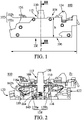
- FIG. 1 shows an embodiment 100 of a stackable electrical contact block according to the present disclosure.
- the electrical contact block 100 is designed to be integrated into a control unit, such as an industrial pushbutton assembly (cf. figure 11 ). By actuating the electrical contact block 100, one can break an electrical contact between two electrical terminals arranged within the contact block. In industrial applications, this allows to stop the supply of electrical current to an electrically driven installation.
- the electrical contact block 100 may be used as part of an emergency stop pushbutton, e.g. to stop a production line in case of a hazard.
- electrical contact blocks there are two types of electrical contact blocks, namely electrical contact blocks that are normally open and electrical contact blocks that are normally closed (the respective shorthand is NO for "normally open”, and NC for "normally closed”).
- the electrical contact block 100 shown in figures 1 to 4 is of the NC-type. It is to be understood that the present disclosure not only covers NC-type contact blocks, but also NO-type contact blocks.
- the electrical contact block 100 comprises a housing 102 that delimits its overall volume.
- the housing 102 consists of a housing cover 102a and a housing main body 102b.
- the cover 102a is fitted onto a lateral side of the main body 102b.
- the cover 102a is removed in order to show the internal structure of the electrical contact block 100.
- the housing 102 has a top side 104 and an opposite bottom side 106.
- the electrical contact block 100 includes the following components, which are all present within the housing 102:
- the two wire inlet pairs 120 and 122 are located on opposite sides of the housing 102. In other words, a first side of the housing 102 has two wire inlets, and a second opposite side of the housing 102 equally has two wire inlets. In the figures, only one wire inlet of each pair 120, 122 is visible on each side of the housing 102.
- Figures 7 and 10 illustrate the electrical contact block 100 with inserted electrical wires W. When inserted, the wires W are in electrical contact with one of the two terminals 108, 110.
- the bottom side 106 and the top side 104 of the housing 102 are each configured as a connection interface for connecting the contact block 100 to another component.
- the contact block 100 can be stacked on to, for example, other contact blocks.
- another contact block can be stacked on top of the illustrated contact block 100. This is shown in figures 7 to 10 .
- the electrical contact block 100 can be assembled with other components in order to build a control device such as an emergency stop pushbutton assembly.
- the bottom connection interface i.e. the housing's bottom side 106 has an entrance 128, see figure 4 .
- the entrance consists of two parallel slits 128a and 128b.
- the actuation pusher 112 can move between a resting position Pr and an actuated position Pa in order to establish a break an electrical contact between the first and second terminals 108 and 110. Since the contact block illustrated in figures 1 to 4 is of the NC-type, the resting position Pr is a closed position where the contact bridge 116 bridges the gap between the two electrical terminals 108 and 110. In this closed position, an electrical current can flow from one terminal to the other. All figures except figure 10 show the actuation pusher 112 in its closed or resting position Pr. In figure 10 , the actuation pusher 112 is depressed and positioned in its actuated position Pa.
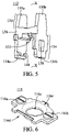
- the actuation pusher 112 is represented on its own in figure 5 . It has an actuation head 130, a cross-link 136, a spring end receiving zone 132 located on the cross-link 136, and a two-pronged (left & right) bridge guiding base 134. The actuation head 130 and the base 134 are connected via the cross-link 136.
- the actuation pusher 112 has an elongated shape, which defines a central longitudinal pusher axis X - X. As can be seen for example in figure 3 , the actuation pusher 112, when viewed from the side, essentially has the shape of the letter H.
- the actuation head 130 of the actuation pusher 112 is fork shaped.
- the fork 130 has two prongs 130a and 130b.
- the bridge guiding base 134 also has a fork shape with a first prong 134a and a second prong 134b. As apparent from figures 2 and 3 , the mobile contact bridge 116 is accommodated in-between the two base prongs 134a and 134b. Each prong 134a, 134b acts as an outer guiding wall for one side of the mobile bridge 116 so that the mobile bridge 116 can slide up and down within the actuation pusher 112.
- the outer lateral walls of the first prong 134a act as guiding surfaces for guiding the sliding motion of the mobile bridge 116.
- a guiding slot 138 is arranged in the second prong 134b.
- the inner walls of the guiding slot 138 also act as guiding surfaces for guiding the sliding motion of the mobile bridge 116.
- the mobile electrical contact bridge 116 is a metallic element with two lateral electrical contact points 116a and 116b, a central through hole 116c, a guiding notch 116d, and a guiding protrusion 116e.
- the guiding notch 116d cooperates with the outer lateral walls of the slot-less guiding prong 134a.
- the guiding notch 116d and the outer lateral walls thus together form an outer guiding assembly.
- the guiding protrusion 116e fits into the guiding slot 138 of the second guiding prong 134b.
- the guiding protrusion 116e and the guiding slot 138 together form an inner guiding assembly.
- the sliding motion of the mobile bridge 116 is guided by two lateral guiding assemblies, namely the outer guiding assembly and the opposite inner guiding assembly.
- the mobile bridge 116 may be guided by two outer guiding assemblies or two inner guiding assemblies.
- both guiding prongs 134a, 134b will be slot-less and the mobile bridge 116 will have two opposite guiding notches 116d.
- both guiding prongs 134a, 134b will have a guiding slot 138 and the mobile bridge 116 will have two opposite guiding protrusions 116e.
- Each contact point 116a, 116b cooperates with one of the electrical terminals 108 and 110.
- the return spring 114 is a helicoidal compression spring. As apparent from figure 3 , it has a bottom end 114a close to the housing's bottom side 106 and a top end 114b close to the housing's top side 104.
- the return spring 114 has a cylindrical shape, which defines a central longitudinal spring axis Y - Y.
- the longitudinal spring axis Y - Y coincides with the longitudinal pusher axis X - X.
- the return spring 114 extends through the contact bridge 116. More specifically, the return spring 114 traverses the central through-hole 116c.
- the function of the return spring 114 is to bias the actuation pusher 112 into its resting position Pr. To do so, its top end 114b pushes against the pusher 112, and its bottom end 114a pushes against the housing 102.
- a spring supporting section 140 is formed in the housing's bottom side 106.
- the spring supporting section 140 supports the bottom end 114a of the return spring 114. As illustrated in figure 4 , the spring supporting section 140 is located in-between the two parallel slits 128a and 128b.
- a clearance 142 is located below the actuation pusher 112, when the actuation pusher 112 is in its resting position Pr.
- the bottom end 114a of the return spring 114 extends into the clearance 142.
- the entrance 128, i.e. the two slits 128a and 128b, provide access to the clearance 142.
- a central part 142a of the clearance 142 is taken up by the bottom end 114a of the return spring 114.
- a peripheral part 142b of the clearance 142, which surrounds the central part 142a, is an actuation head receiving space.
- the actuation head receiving space 142b is adapted for receiving the actuation head 130 of a component connected to the contact block via its bottom side 106.
- the actuation head receiving space 142b is subdivided into two separate receiving zones. Each zone can receive one of the two prongs 130a, 130b of a fork shaped actuation head 130.
- the contact spring 118 biases the contact bridge 116 towards the first and second terminals 108 and 110.
- the contact spring 118 is fitted into the base part 134 of the actuation pusher 112. The top portion of the contact spring 118 pushes against the bottom side of the contact bridge 116. The bottom portion of the contact spring 118 rests on a ledge 144 of the base part 134.
- the contact spring 118 is a helicoidal compression spring. Accordingly, it has a cylindrical shape.
- the return spring 114 extends through the contact spring 118.
- the contact spring and the return spring are arranged coaxially. In this case, they share a common longitudinal axis Y - Y.
- the diameter of the return spring 114 is smaller than the diameter of the contact spring 118.
- the actuation head 130 protrudes from the housing's top side 104, cf. figures 1 and 2 .
- the electrical contact block 100 is then actuated by pushing the actuation pusher 112 into the housing 102. This is done by depressing the actuation head 130.
- the pressure exerted on the actuation head 130 has to be sufficient to overcome the opposing force exerted by the return spring 114.
- the actuation pusher 112 then moves towards the housing's bottom side 106 until it reaches its actuated position Pa shown in figure 10 . In this position, the actuation head 130 is completely retracted into the housing 102.
- the mobile contact bridge 116 which moves in unison with the actuation pusher 112, is separated from the electrical terminals 108 and 110. Accordingly, the electrical contact between the first and second terminals 108, 110 is broken.
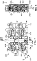
- Figures 7 to 9 show a stack where the upper contact block is a normally-open block 200 and the lower contact block is a normally-closed block.
- the scope of the present disclosure also extends to these NO-type contact blocks, which have the same inventive design as to the bottom side entrance, the clearance below the actuation pusher, and the arrangement of the return spring, the contact spring and the contact bridge.
- Figure 11 is a perspective view of a pushbutton assembly 300, including two stacks 302 and 304 of two contact blocks according to the present disclosure.
- the left stack 302 is made of an upper contact block 100 of the NC - type and a lower contact block 200 of the NO - type.
- the right stack 304 is made of an upper contact block 200 of the NO - type and a lower contact block 100 of the NC - type.
- the assembly 300 has a total of four contact blocks. With the help of a collar 306, the four contact blocks amounted to a pushbutton 308.
- a particularity of the contact blocks 100, 200 of the present disclosure is their low profile. Indeed, typically, the ratio between the height h and the length I of the housing 102 of the contact block is less than 0.4 (cf. figure 1 ). Thanks to the small height h, more contact blocks 100, 200 can be assembled behind a collar 306 and still fit into a slim control panel.
- the new contact block architecture described in the present disclosure is particularly suited to meet all current customer needs:
- the contact blocks 100, 200 of the present disclosure are also fully compliant with the industry safety standards regarding clearance and creepage distance.
Abstract
Description
- This disclosure pertains to a stackable electrical contact block comprising a housing that delimits its volume, wherein the housing has a top side and an opposite bottom side, wherein the following elements are present within the housing:
- a first and second electrical terminal;
- an actuation pusher adapted to move between a resting position and an actuated position in order to establish or break an electrical contact between the first and second terminals, the actuation pusher having an actuation head, which, in the resting position, protrudes from the housing's top side;
- a clearance below the actuation pusher, when the actuation pusher is in its resting position; and
- a return spring biasing the actuation pusher towards its resting position, a bottom end of the return spring extending into the clearance.
- This type of electrical contact block is known. An example is disclosed in
Figs. 1 and8 to10 ofWO 2015/091497 A1 . - Such a contact block has the advantage of a low profile. However, it is not fully stackable, which limits its use as a module, for example as part of a push button assembly. In particular, this prior art contact block cannot be used as an upper or intermediate member of a contact block stack.
- In view of the above, it is an object of the present disclosure to provide a low-profile electrical contact block, which is fully stackable.
- According to the present disclosure, this object is achieved with an electrical contact block as defined above in § [0001], which is characterised in that the housing's bottom side is configured as a connection interface with an entrance providing access to the clearance, for connecting the contact block to another component, and in that a central part of the clearance is taken up by the bottom end of the return spring, and a peripheral part of the clearance, which surrounds the central part, is an actuation head receiving space adapted for receiving the actuation head of a component connected to the contact block via the connection interface.
- By making the housing's bottom side into a connection interface, the contact block of the present disclosure can be easily stacked onto another component, and in particular onto another contact block. During stacking, thanks to the bottom side entrance, the actuation head of the lower contact block can be inserted into the clearance of the upper contact block. As a result, the actuation head of the lower contact block is arranged below the pusher of the upper contact block so that it can cooperate therewith. By locating the bottom end of the return spring in the centre of the clearance, a peripheral part of the clearance remains unobstructed, which allows the insertion of the actuation head of the lower contact block into the upper contact block.
- The following features can be optionally implemented, separately or in combination one with the others:
- the actuation pusher has an elongate shape defining a central longitudinal pusher axis, wherein the return spring has a cylindrical shape defining a central longitudinal spring axis, and wherein both axes essentially coincide;
- a mobile electrical contact bridge for establishing and breaking the electrical contact between the first and second terminals, wherein the contact bridge is accommodated in the actuation pusher, and wherein the return spring extends through the contact bridge;
- a contact spring biasing the contact bridge towards the first and second terminals, wherein the return spring extends through the contact spring;
- the contact spring and the return spring are arranged coaxially;
- the contact bridge has a central through hole, which is traversed by the return spring;
- the entrance consists of two parallel slits adapted for receiving the prongs of a fork-shaped actuation head;
- a spring supporting section formed in the housing's bottom side for supporting the bottom end of the return spring, wherein the spring supporting section is located in-between the two parallel slits;
- the actuation pusher, when viewed from the side, essentially has the shape of the letter H;
- the actuation head of the actuation pusher is fork-shaped;
- the ratio between the housing's height and length is less than 0.4.
- These and other features and advantages are detailed in the following description of preferred embodiments and in the accompanying figures, of which:
-
Figure 1 is a side view of an electrical contact block of the normally closed type according to the present disclosure; -
Figure 2 is a side view similar to that offigure 1 , where the housing cover is removed; -
Figure 3 is a cross-sectional view of the electrical contact block taken along line III - III offigure 1 ; -
Figure 4 is a bottom view, according to the arrow IV infigure 1 ; -
Figure 5 is a perspective view of an actuation pusher according to the present disclosure; -
Figure 6 is a perspective view of an electrical contact bridge according to the present disclosure; -
Figure 7 is a stack of two electrical contact blocks of the present disclosure, one of the normally closed and one of the normally open type; -
Figure 8 is a cross-sectional view of the stack offigure 7 , taken along line VIII - VIII; -
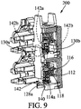
Figure 9 is a perspective view of a detail of the stack offigure 7 ; -
Figure 10 is a side view of a stack of two electrical contact blocks of the present disclosure, both being of the normally closed type, and both being in their actuated position; and -
Figure 11 is a perspective view of a pushbutton assembly according to the present disclosure, including four electrical contact blocks. - Reference is first made to
figures 1 to 4 . These figures show anembodiment 100 of a stackable electrical contact block according to the present disclosure. - The
electrical contact block 100 is designed to be integrated into a control unit, such as an industrial pushbutton assembly (cf.figure 11 ). By actuating theelectrical contact block 100, one can break an electrical contact between two electrical terminals arranged within the contact block. In industrial applications, this allows to stop the supply of electrical current to an electrically driven installation. For example, theelectrical contact block 100 may be used as part of an emergency stop pushbutton, e.g. to stop a production line in case of a hazard. - Generally, there are two types of electrical contact blocks, namely electrical contact blocks that are normally open and electrical contact blocks that are normally closed (the respective shorthand is NO for "normally open", and NC for "normally closed").
- The
electrical contact block 100 shown infigures 1 to 4 is of the NC-type. It is to be understood that the present disclosure not only covers NC-type contact blocks, but also NO-type contact blocks. - With reference to
figures 1 to 4 , theelectrical contact block 100 comprises ahousing 102 that delimits its overall volume. Thehousing 102 consists of ahousing cover 102a and a housingmain body 102b. Thecover 102a is fitted onto a lateral side of themain body 102b. Infigure 2 , thecover 102a is removed in order to show the internal structure of theelectrical contact block 100. Thehousing 102 has atop side 104 and anopposite bottom side 106. - The
electrical contact block 100 includes the following components, which are all present within the housing 102: - first and second
electrical terminals - an
actuation pusher 112, - a
return spring 114, - a mobile
electrical contact bridge 116, - a
contact spring 118; and - two wire inlet pairs 120 and 122.
- The two wire inlet pairs 120 and 122 are located on opposite sides of the
housing 102. In other words, a first side of thehousing 102 has two wire inlets, and a second opposite side of thehousing 102 equally has two wire inlets. In the figures, only one wire inlet of eachpair housing 102.Figures 7 and10 illustrate theelectrical contact block 100 with inserted electrical wires W. When inserted, the wires W are in electrical contact with one of the twoterminals - The
bottom side 106 and thetop side 104 of thehousing 102 are each configured as a connection interface for connecting thecontact block 100 to another component. In this way, thecontact block 100 can be stacked on to, for example, other contact blocks. Likewise, another contact block can be stacked on top of the illustratedcontact block 100. This is shown infigures 7 to 10 . Accordingly, theelectrical contact block 100 can be assembled with other components in order to build a control device such as an emergency stop pushbutton assembly. - When another contact block is mounted onto the
top side 104 of thecontact block 100, it is fastened thereto with the help of adouble hook 124 and anopposite fastening shoe 126. - The bottom connection interface, i.e. the housing's
bottom side 106 has anentrance 128, seefigure 4 . Preferably, the entrance consists of twoparallel slits - The
actuation pusher 112 can move between a resting position Pr and an actuated position Pa in order to establish a break an electrical contact between the first andsecond terminals figures 1 to 4 is of the NC-type, the resting position Pr is a closed position where thecontact bridge 116 bridges the gap between the twoelectrical terminals figure 10 show theactuation pusher 112 in its closed or resting position Pr. Infigure 10 , theactuation pusher 112 is depressed and positioned in its actuated position Pa. - The
actuation pusher 112 is represented on its own infigure 5 . It has anactuation head 130, across-link 136, a springend receiving zone 132 located on thecross-link 136, and a two-pronged (left & right)bridge guiding base 134. Theactuation head 130 and the base 134 are connected via thecross-link 136. Theactuation pusher 112 has an elongated shape, which defines a central longitudinal pusher axis X - X. As can be seen for example infigure 3 , theactuation pusher 112, when viewed from the side, essentially has the shape of the letter H. One will also note that theactuation head 130 of theactuation pusher 112 is fork shaped. Thefork 130 has twoprongs - The
bridge guiding base 134 also has a fork shape with afirst prong 134a and asecond prong 134b. As apparent fromfigures 2 and3 , themobile contact bridge 116 is accommodated in-between the twobase prongs prong mobile bridge 116 so that themobile bridge 116 can slide up and down within theactuation pusher 112. - The outer lateral walls of the
first prong 134a act as guiding surfaces for guiding the sliding motion of themobile bridge 116. A guidingslot 138 is arranged in thesecond prong 134b. The inner walls of the guidingslot 138 also act as guiding surfaces for guiding the sliding motion of themobile bridge 116. - Turning now to
figure 6 , the mobileelectrical contact bridge 116 is a metallic element with two lateralelectrical contact points hole 116c, a guidingnotch 116d, and a guidingprotrusion 116e. The guidingnotch 116d cooperates with the outer lateral walls of theslot-less guiding prong 134a. The guidingnotch 116d and the outer lateral walls thus together form an outer guiding assembly. The guidingprotrusion 116e fits into the guidingslot 138 of thesecond guiding prong 134b. Hence, the guidingprotrusion 116e and the guidingslot 138 together form an inner guiding assembly. Overall, the sliding motion of themobile bridge 116 is guided by two lateral guiding assemblies, namely the outer guiding assembly and the opposite inner guiding assembly. - Alternatively, the
mobile bridge 116 may be guided by two outer guiding assemblies or two inner guiding assemblies. In the first case, both guidingprongs mobile bridge 116 will have twoopposite guiding notches 116d. In the second case, both guidingprongs slot 138 and themobile bridge 116 will have two opposite guidingprotrusions 116e. - Each
contact point electrical terminals - In the illustrated embodiments, the
return spring 114 is a helicoidal compression spring. As apparent fromfigure 3 , it has abottom end 114a close to the housing'sbottom side 106 and atop end 114b close to the housing'stop side 104. Thereturn spring 114 has a cylindrical shape, which defines a central longitudinal spring axis Y - Y. The longitudinal spring axis Y - Y coincides with the longitudinal pusher axis X - X. Thereturn spring 114 extends through thecontact bridge 116. More specifically, thereturn spring 114 traverses the central through-hole 116c. The function of thereturn spring 114 is to bias theactuation pusher 112 into its resting position Pr. To do so, itstop end 114b pushes against thepusher 112, and itsbottom end 114a pushes against thehousing 102. - The
top end 114b of thereturn spring 114 is received in the springend receiving zone 132 of theactuation pusher 112. Aspring supporting section 140 is formed in the housing'sbottom side 106. Thespring supporting section 140 supports thebottom end 114a of thereturn spring 114. As illustrated infigure 4 , thespring supporting section 140 is located in-between the twoparallel slits - As best seen in
figure 9 , aclearance 142 is located below theactuation pusher 112, when theactuation pusher 112 is in its resting position Pr. Thebottom end 114a of thereturn spring 114 extends into theclearance 142. Theentrance 128, i.e. the twoslits clearance 142. Acentral part 142a of theclearance 142 is taken up by thebottom end 114a of thereturn spring 114. Aperipheral part 142b of theclearance 142, which surrounds thecentral part 142a, is an actuation head receiving space. As can be seen infigures 7 to 9 , the actuationhead receiving space 142b is adapted for receiving theactuation head 130 of a component connected to the contact block via itsbottom side 106. The actuationhead receiving space 142b is subdivided into two separate receiving zones. Each zone can receive one of the twoprongs actuation head 130. - With reference to
figure 2 , thecontact spring 118 biases thecontact bridge 116 towards the first andsecond terminals figure 3 , thecontact spring 118 is fitted into thebase part 134 of theactuation pusher 112. The top portion of thecontact spring 118 pushes against the bottom side of thecontact bridge 116. The bottom portion of thecontact spring 118 rests on aledge 144 of thebase part 134. In the illustrated embodiments, thecontact spring 118 is a helicoidal compression spring. Accordingly, it has a cylindrical shape. As shown infigure 3 , thereturn spring 114 extends through thecontact spring 118. Preferably, the contact spring and the return spring are arranged coaxially. In this case, they share a common longitudinal axis Y - Y. Preferably, the diameter of thereturn spring 114 is smaller than the diameter of thecontact spring 118. - We will now explain the operation of the
electrical contact block 100. In the resting position Pr, theactuation head 130 protrudes from the housing'stop side 104, cf.figures 1 and 2 . Theelectrical contact block 100 is then actuated by pushing theactuation pusher 112 into thehousing 102. This is done by depressing theactuation head 130. The pressure exerted on theactuation head 130 has to be sufficient to overcome the opposing force exerted by thereturn spring 114. Theactuation pusher 112 then moves towards the housing'sbottom side 106 until it reaches its actuated position Pa shown infigure 10 . In this position, theactuation head 130 is completely retracted into thehousing 102. Themobile contact bridge 116, which moves in unison with theactuation pusher 112, is separated from theelectrical terminals second terminals - In order to attach a contact block to the
bottom side 106 of thecontact block 100, one has to insert theprongs actuation head 130 of the contact block into theparallel slits contact block 100. In this way, theprongs head receiving space 142 of thecontact block 100. As can be seen infigures 7 to 9 , where two contact blocks are assembled to form a stack, the twoprongs actuation head 130 of the lower contact block are arranged directly below the actuation pusher of the upper contact block. Accordingly, when the upper actuation pusher is depressed, the downward force is directly transmitted to the lower actuation pusher so that both contact blocks are actuated simultaneously. -
Figures 7 to 9 show a stack where the upper contact block is a normally-open block 200 and the lower contact block is a normally-closed block. The scope of the present disclosure also extends to these NO-type contact blocks, which have the same inventive design as to the bottom side entrance, the clearance below the actuation pusher, and the arrangement of the return spring, the contact spring and the contact bridge. -
Figure 11 is a perspective view of apushbutton assembly 300, including twostacks left stack 302 is made of anupper contact block 100 of the NC - type and alower contact block 200 of the NO - type. Theright stack 304 is made of anupper contact block 200 of the NO - type and alower contact block 100 of the NC - type. Hence, theassembly 300 has a total of four contact blocks. With the help of acollar 306, the four contact blocks amounted to apushbutton 308. - A particularity of the contact blocks 100, 200 of the present disclosure is their low profile. Indeed, typically, the ratio between the height h and the length I of the
housing 102 of the contact block is less than 0.4 (cf.figure 1 ). Thanks to the small height h, more contact blocks 100, 200 can be assembled behind acollar 306 and still fit into a slim control panel. - The new contact block architecture described in the present disclosure is particularly suited to meet all current customer needs:
- The new contact blocks 100, 200 are compatible with state-of-the-art contact blocks. This means in particular that the new contact blocks 100, 200 can be stacked under existing contact blocks;
- The new contact blocks 100, 200 are fully stackable onto each other, regardless of the order of stacking;
- Compared to conventional contact blocks with their larger height, more of the new contact blocks 100, 200 of the present disclosure can be mounted into the same available head space.
- The contact blocks 100, 200 of the present disclosure are also fully compliant with the industry safety standards regarding clearance and creepage distance.
- This disclosure is not limited to the specific embodiments described herein, which are only examples. The invention encompasses every alternative that is still covered by the appended claims.
Claims (11)
- A stackable electrical contact block (100) comprising a housing (102) that delimits its volume, wherein the housing (102) has a top side (104) and an opposite bottom side (106), wherein the following elements are present within the housing (102):- a first (108) and second (110) electrical terminal;- an actuation pusher (112) adapted to move between a resting position (Pr) and an actuated position (Pa) in order to establish or break an electrical contact between the first and second terminals (108, 110), the actuation pusher (112) having an actuation head (130), which, in the resting position (Pr), protrudes from the housing's top side (104);- a clearance (142) below the actuation pusher, when the actuation pusher is in its resting position (Pr); and- a return spring (114) biasing the actuation pusher (112) towards its resting position, a bottom end (114a) of the return spring extending into the clearance (142),characterised in that:- the housing's bottom side (106) is configured as a connection interface with an entrance (128) providing access to the clearance (142), for connecting the contact block (100) to another component,- a central part (142a) of the clearance is taken up by the bottom end (114a) of the return spring (114), and a peripheral part (142b) of the clearance, which surrounds the central part (142a), is an actuation head receiving space adapted for receiving the actuation head (130) of a component connected to the contact block (100) via the connection interface.
- The contact block (100) of claim 1, wherein the actuation pusher (112) has an elongate shape defining a central longitudinal pusher axis (X-X), wherein the return spring (114) has a cylindrical shape defining a central longitudinal spring axis (Y-Y), and wherein both axes essentially coincide.
- The contact block (100) of claim 1 or 2, further comprising a mobile electrical contact bridge (116) for establishing and breaking the electrical contact between the first and second terminals (108, 110), wherein the contact bridge (116) is accommodated in the actuation pusher (112), and wherein the return spring (114) extends through the contact bridge (116).
- The contact block (100) of claim 3, further comprising a contact spring (118) biasing the contact bridge (116) towards the first and second terminals (108, 110), wherein the return spring (114) extends through the contact spring (118).
- The contact block (100) of claim 4, wherein the contact spring (118) and the return spring (114) are arranged coaxially.
- The contact block (100) of any one of claims 3 to 5, wherein the contact bridge (116) has a central through hole (116c), which is traversed by the return spring (114).
- The contact block (100) of any one of the previous claims, wherein the entrance (128) consists of two parallel slits (128a, 128b) adapted for receiving the prongs (130a, 130b) of a fork-shaped actuation head (130).
- The contact block (100) of claim 7, further comprising a spring supporting section (140) formed in the housing's bottom side (106) for supporting the bottom end (114a) of the return spring, wherein the spring supporting section (140) is located in-between the two parallel slits (128a, 128b).
- The contact block (100) of any one of the previous claims, wherein the actuation pusher (112), when viewed from the side, essentially has the shape of the letter H.
- The contact block (100) of any one of the previous claims, wherein the actuation head (130) of the actuation pusher is fork-shaped.
- The contact block (100) of any one of the previous claims, wherein the ratio between the housing's height (h) and length (I) is less than 0.4.
Priority Applications (4)
| Application Number | Priority Date | Filing Date | Title |
|---|---|---|---|
| EP20306297.1A EP3993000A1 (en) | 2020-10-29 | 2020-10-29 | Stackable low-profile electrical contact block |
| CN202111066996.2A CN114430129A (en) | 2020-10-29 | 2021-09-13 | Stackable low profile electrical contact block |
| JP2021170306A JP2022074023A (en) | 2020-10-29 | 2021-10-18 | Stackable low profile electrical contact block |
| US17/509,118 US11837417B2 (en) | 2020-10-29 | 2021-10-25 | Stackable low-profile electrical contact block |
Applications Claiming Priority (1)
| Application Number | Priority Date | Filing Date | Title |
|---|---|---|---|
| EP20306297.1A EP3993000A1 (en) | 2020-10-29 | 2020-10-29 | Stackable low-profile electrical contact block |
Publications (1)
| Publication Number | Publication Date |
|---|---|
| EP3993000A1 true EP3993000A1 (en) | 2022-05-04 |
Family
ID=73288541
Family Applications (1)
| Application Number | Title | Priority Date | Filing Date |
|---|---|---|---|
| EP20306297.1A Pending EP3993000A1 (en) | 2020-10-29 | 2020-10-29 | Stackable low-profile electrical contact block |
Country Status (4)
| Country | Link |
|---|---|
| US (1) | US11837417B2 (en) |
| EP (1) | EP3993000A1 (en) |
| JP (1) | JP2022074023A (en) |
| CN (1) | CN114430129A (en) |
Citations (2)
| Publication number | Priority date | Publication date | Assignee | Title |
|---|---|---|---|---|
| DE19856678A1 (en) * | 1998-12-04 | 2001-04-05 | Moeller Gmbh | Contact element |
| WO2015091497A1 (en) | 2013-12-19 | 2015-06-25 | Eaton Electrical Ip Gmbh & Co. Kg | Contact element |
Family Cites Families (2)
| Publication number | Priority date | Publication date | Assignee | Title |
|---|---|---|---|---|
| US4255633A (en) * | 1979-06-04 | 1981-03-10 | Westinghouse Electric Corp. | Push-pull switch operator |
| US6822173B1 (en) * | 2000-06-07 | 2004-11-23 | Moeller Gmbh | Contact element |
-
2020
- 2020-10-29 EP EP20306297.1A patent/EP3993000A1/en active Pending
-
2021
- 2021-09-13 CN CN202111066996.2A patent/CN114430129A/en active Pending
- 2021-10-18 JP JP2021170306A patent/JP2022074023A/en active Pending
- 2021-10-25 US US17/509,118 patent/US11837417B2/en active Active
Patent Citations (2)
| Publication number | Priority date | Publication date | Assignee | Title |
|---|---|---|---|---|
| DE19856678A1 (en) * | 1998-12-04 | 2001-04-05 | Moeller Gmbh | Contact element |
| WO2015091497A1 (en) | 2013-12-19 | 2015-06-25 | Eaton Electrical Ip Gmbh & Co. Kg | Contact element |
Also Published As
| Publication number | Publication date |
|---|---|
| US20220139646A1 (en) | 2022-05-05 |
| CN114430129A (en) | 2022-05-03 |
| US11837417B2 (en) | 2023-12-05 |
| JP2022074023A (en) | 2022-05-17 |
Similar Documents
| Publication | Publication Date | Title |
|---|---|---|
| CN106340730B (en) | Push-in clip type retainer, push-in clip assembly and electrical connector element | |
| US8915758B2 (en) | Electrical connector | |
| US7862389B2 (en) | Terminal block with U-shaped conducting part for connecting electric wires | |
| US6062918A (en) | Electrical receptacle contact assembly | |
| KR101478585B1 (en) | Wire-to-board connector | |
| CN1988263B (en) | Electrical device, particularly relay socket, with spring clip and method of manufacture | |
| US5108300A (en) | Electrical connector with interlocked components | |
| US4308440A (en) | Switch contact positioning assembly | |
| WO2003077368A2 (en) | Push-in wire connector | |
| US8801456B2 (en) | Connector | |
| ZA200209282B (en) | Fuse. | |
| EP2930792A1 (en) | Wire-to-board connector | |
| CN100477389C (en) | Connector for at least one flexible flat strip cable | |
| JPH05190233A (en) | Connector | |
| CN108631102B (en) | Female connector and connection structure of female connector and male connector | |
| JP7395112B2 (en) | female terminal | |
| CN102195176A (en) | Plug connector | |
| EP3993000A1 (en) | Stackable low-profile electrical contact block | |
| US6642823B2 (en) | Contact block assembly and a method of assembling a contact block assembly | |
| KR20150107601A (en) | Electromagnetic contactor | |
| CN111247697B (en) | Flat electric connector | |
| US20220344852A1 (en) | Conductor connection terminal | |
| GB2080032A (en) | A plug for masking switching contacts | |
| CN112563774A (en) | Connector with a locking member | |
| GB2058458A (en) | Key switch |
Legal Events
| Date | Code | Title | Description |
|---|---|---|---|
| PUAI | Public reference made under article 153(3) epc to a published international application that has entered the european phase |
Free format text: ORIGINAL CODE: 0009012 |
|
| STAA | Information on the status of an ep patent application or granted ep patent |
Free format text: STATUS: THE APPLICATION HAS BEEN PUBLISHED |
|
| AK | Designated contracting states |
Kind code of ref document: A1 Designated state(s): AL AT BE BG CH CY CZ DE DK EE ES FI FR GB GR HR HU IE IS IT LI LT LU LV MC MK MT NL NO PL PT RO RS SE SI SK SM TR |
|
| STAA | Information on the status of an ep patent application or granted ep patent |
Free format text: STATUS: REQUEST FOR EXAMINATION WAS MADE |
|
| 17P | Request for examination filed |
Effective date: 20221026 |
|
| RBV | Designated contracting states (corrected) |
Designated state(s): AL AT BE BG CH CY CZ DE DK EE ES FI FR GB GR HR HU IE IS IT LI LT LU LV MC MK MT NL NO PL PT RO RS SE SI SK SM TR |