EP3992899A1 - Iris verification device, iris verification method, computer program and recording medium - Google Patents
Iris verification device, iris verification method, computer program and recording medium Download PDFInfo
- Publication number
- EP3992899A1 EP3992899A1 EP19934618.0A EP19934618A EP3992899A1 EP 3992899 A1 EP3992899 A1 EP 3992899A1 EP 19934618 A EP19934618 A EP 19934618A EP 3992899 A1 EP3992899 A1 EP 3992899A1
- Authority
- EP
- European Patent Office
- Prior art keywords
- iris
- iris recognition
- imaging
- image
- recognition apparatus
- Prior art date
- Legal status (The legal status is an assumption and is not a legal conclusion. Google has not performed a legal analysis and makes no representation as to the accuracy of the status listed.)
- Withdrawn
Links
Images


Classifications
-
- G—PHYSICS
- G06—COMPUTING OR CALCULATING; COUNTING
- G06V—IMAGE OR VIDEO RECOGNITION OR UNDERSTANDING
- G06V40/00—Recognition of biometric, human-related or animal-related patterns in image or video data
- G06V40/10—Human or animal bodies, e.g. vehicle occupants or pedestrians; Body parts, e.g. hands
- G06V40/18—Eye characteristics, e.g. of the iris
- G06V40/19—Sensors therefor
-
- G—PHYSICS
- G02—OPTICS
- G02B—OPTICAL ELEMENTS, SYSTEMS OR APPARATUS
- G02B3/00—Simple or compound lenses
- G02B3/12—Fluid-filled or evacuated lenses
- G02B3/14—Fluid-filled or evacuated lenses of variable focal length
-
- G—PHYSICS
- G02—OPTICS
- G02B—OPTICAL ELEMENTS, SYSTEMS OR APPARATUS
- G02B7/00—Mountings, adjusting means, or light-tight connections, for optical elements
- G02B7/28—Systems for automatic generation of focusing signals
- G02B7/36—Systems for automatic generation of focusing signals using image sharpness techniques, e.g. image processing techniques for generating autofocus signals
-
- H—ELECTRICITY
- H04—ELECTRIC COMMUNICATION TECHNIQUE
- H04N—PICTORIAL COMMUNICATION, e.g. TELEVISION
- H04N23/00—Cameras or camera modules comprising electronic image sensors; Control thereof
- H04N23/60—Control of cameras or camera modules
-
- H—ELECTRICITY
- H04—ELECTRIC COMMUNICATION TECHNIQUE
- H04N—PICTORIAL COMMUNICATION, e.g. TELEVISION
- H04N23/00—Cameras or camera modules comprising electronic image sensors; Control thereof
- H04N23/60—Control of cameras or camera modules
- H04N23/61—Control of cameras or camera modules based on recognised objects
- H04N23/611—Control of cameras or camera modules based on recognised objects where the recognised objects include parts of the human body
-
- H—ELECTRICITY
- H04—ELECTRIC COMMUNICATION TECHNIQUE
- H04N—PICTORIAL COMMUNICATION, e.g. TELEVISION
- H04N23/00—Cameras or camera modules comprising electronic image sensors; Control thereof
- H04N23/60—Control of cameras or camera modules
- H04N23/67—Focus control based on electronic image sensor signals
Definitions
- This disclosure relates to the technical field of an iris recognition apparatus, an iris recognition method, a computer program and a recording medium.
- This type of apparatus has a technical problem in that if a distance between an iris (i.e., a subject) of a target person and a camera changes during imaging, it is difficult to image an image in focus.
- an apparatus imaging a plurality of images by moving a lens of a camera in an optical axis direction so as to focus at each of a plurality of focusing positions predetermined, then selecting one image, which is estimated to be in focus, from the plurality of images, and performing iris recognition (see Patent Literature 1).
- Patent Literatures 2 and 3 are listed as other related technique.
- Patent Literature 1 even if an image imaged at first is an image in focus, iris recognition is not performed until a plurality of images are imaged. Therefore, the technique described in Patent Literature 1 has a technical problem that the time required for iris recognition becomes relatively long.
- An object of this disclosure is to provide an iris recognition apparatus, an iris recognition method, a computer program, and a recording medium, that can reduce the time required for iris recognition.
- An aspect of an iris recognition apparatus of this disclosure is an iris recognition apparatus for performing recognition of a target person based on an iris pattern of the target person, the iris recognition apparatus is provided with: an imaging device that performs an imaging processing for sequentially outputting imaged images while changing a focal position; and a determining device that starts a focusing determination for determining whether or not an image is a focused image before the imaging device completes the imaging processing.
- An aspect of an iris recognition method of this disclosure is an iris recognition method for performing recognition for a target person based on an iris pattern of the target person in an iris recognition apparatus having an imaging device, the iris recognition method comprising: the imaging device performing an imaging processing for sequentially outputting imaged images while changing a focal position; and starting a focusing determination for determining whether or not an image is a focused image before the imaging device completes the imaging processing.
- An aspect of a computer program of this disclosure causes a computer to execute the one aspect of the iris recognition method as described above.
- An aspect of a recording medium of this disclosure is a recording medium in which the one aspect of the computer program as described above is recorded.
- each of the iris recognition apparatus, the iris recognition method, the computer program, and the recording medium as described above it is possible to reduce the time required for iris recognition.
- iris recognition recognition for a target person is performed based on the iris pattern of the target person.
- An iris which is a doughnut-shaped tissue, has a very complex and indigenous pattern for each person.
- a diameter of an iris of a person is about 1 cm. It is desirable to image an iris at an imaging magnification of, for example, about 50 ⁇ m/px in order to perform iris recognition using images, in which an iris is imaged. If a target person (in other words, a subject) moves slightly due to, for example, reflective motion, etc. during imaging, an iris may be out of focus.
- an iris recognition apparatus which can perform iris recognition even if a target person moves slightly.
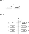
- Fig. 1 is a block diagram showing the entire configuration of iris recognition apparatus 1 of the embodiment.
- the iris recognition apparatus 1 is configured to comprise the iris recognition unit 10 and the iris camera 20.
- the iris camera 20 is installed so that an eye area of a target person can be suitably imaged when the target person of iris recognition is at a predetermined place (e.g., at a position designated by a footprint mark, at a position to be seated, etc.).
- the iris camera 20 corresponds to an example of an "imaging unit" in supplementary note described later.
- FIG. 2 is a block diagram showing a hardware configuration of the iris recognition unit 10 of the embodiment.
- the iris recognition unit 10 comprises the CPU (Central Processing Unit) 11, the RAM (Random Access Memory) 12, the ROM (Read Only Memory) 13, the storage apparatus 14, the input device 15 and the output device 16.
- the CPU 11, the RAM 12, the ROM 13, the storage apparatus 14, the input device 15 and the output device 16 are interconnected each other via a data bus 17.
- the CPU 11 reads computer programs.
- the CPU 11 may read a computer program stored in at least one of the RAM 12, the ROM 13 and the storage apparatus 14.
- the CPU 11 may read a computer program stored in a computer-readable recording medium by using a recording medium reading apparatus not shown.
- the CPU 11 may acquire (i.e., read) a computer program from an apparatus not shown located outside the iris recognition unit 10 via a network interface.
- the CPU 11 controls the RAM 12, the storage apparatus 14, the input device 15 and the output device 16 by executing the read computer program.
- logical functional blocks for performing iris recognition are implemented in the CPU 11 by the CPU 11 executing the read computer program.
- the CPU 11 can function as a controller for performing iris recognition.
- the image acquiring unit 111, the focusing determining unit 112, the recognition unit 113 and the camera controlling unit 114 are realized as logical functional blocks.
- the operation of each of the image acquiring unit 111, the focusing determining unit 112, the recognition unit 113 and the camera controlling unit 114 will be described later.
- the focusing determining unit 112 and the camera controlling unit 114 correspond to examples of a "determining device” and a “controlling device” in supplementary note to be described later.
- the RAM 12 temporarily stores computer programs executed by CPU11.
- the RAM 12 temporarily stores data that the CPU 11 uses temporarily while the CPU 11 executes computer programs.
- the RAM 12 may be, for example, D-RAM (Dynamic RAM).
- the ROM 13 stores computer programs executed by the CPU 11.
- the ROM 13 may store other fixed data.
- the ROM 13 may be, for example, P-ROM (Programmable ROM).
- the storage apparatus 14 stores data that the iris recognition apparatus 1 saves in long-term.
- the storage apparatus 14 may act as a temporary storage apparatus for the CPU 11.
- the storage apparatus 14 may include, for example, at least one of a hard disk apparatus, a magneto-optical disk apparatus, an SSD (Solid State Drive) and a disk array apparatus.
- the input device 15 is an apparatus that receives input instructions from a user of the iris recognition apparatus 1.
- the input device 15 may include, for example, at least one of a keyboard, a mouse and a touch panel.
- the output device 16 is an apparatus for outputting information about the iris recognition apparatus 1 to the outside.
- the output device 16 may be a display apparatus capable of displaying information about the iris recognition apparatus 1.
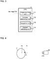
- FIG. 4 is a conceptual diagram showing a concept of a moving range of a focal position of the iris camera of the embodiment.
- the iris camera 20 performs imaging while changing the focal position between the position P1 and the position P2 on the optical axis thereof. More specifically, the iris camera 20 performs imaging while changing the focal position so as to gradually approach the position P2 from the position P1. Thereafter, the iris camera 20 performs imaging while changing the focal position so as to gradually approach the position P1 from the position P2. This operation may be performed repeatedly or only once. It is needless to say that the iris camera 20 may perform imaging while changing the focal position so as to gradually approach the position P1 from the position P2, and then perform imaging while changing the focal position so as to gradually approach the position P2 from the position P1.
- the iris camera 20 does not adjust its focal position (i.e., focus) on the basis of, for example, the distance between the target person T and the iris camera 20 during imaging.
- the iris recognition apparatus 1 assumes that the target person T moves slightly due to, for example, reflective motion or the like. In other words, even if the distance between the target person T and the iris camera 20 at a certain moment is detected, the distance may change due to the slightly movement of the target person T at the next moment.
- the iris camera 20 images an area (e.g., an area between the position P1 and the position P2 in FIG. 4 ) where the target person T (strictly speaking, the iris of the target person T) would be present, while changing the focal position.
- the iris camera 20 has an optical system capable of changing the focal position (e.g., a lens, hereinafter, such an optical system referred to as "imaging lens” for convenience).
- the imaging lens may include a lens capable of changing the focal position by physically moving along the optical axis direction of the imaging lens.
- the imaging lens may include a lens capable of changing the focal position without moving along the optical axis direction of the imaging lens.
- a liquid lens, A liquid crystal lens, or the like are listed as the lens capable of changing the focal position without moving along the optical axis direction of the imaging lens.
- the description will be advanced using an example in which the iris camera 20 has the liquid lens 210 as an imaging lens. Incidentally, since it is possible to apply the existing various aspects to the liquid lens, a detailed description thereof will be omitted.
- the iris camera 20 changes the focal position as described above by changing the applied voltage applied to the liquid lens 210.
- the iris camera 20 performs imaging while changing the focal position as described above (in other words, while moving the focal length) (step Sill).
- the iris camera 20 may detect the distance between the target person T and the iris camera 20, and may start imaging (i.e., the processing of the step S111 may be started) when the detected distance becomes a predetermined distance. Images imaged in the processing of the step S111 are outputted to the iris recognition unit 10 (step S112).
- the iris camera 20 determines whether or not the focal position has reached the border (corresponding to each of positions P1 and P2 in FIG. 4 ) of the area, in which at which the focal position should be changed (step S113). In the processing of the step S113, if it is determined that the focal position does not reach the boundary (step S113: No), the processing of the step S111 is performed. In this case, in the processing of the step S111, the focal point is moved in the same direction as the direction in which the focal position was moved in the previous processing of the step S111.
- the focal position is moved by more increasing the applied voltage applied to the liquid lens 210.
- the iris camera 20 moves the focal position by decreasing the applied voltage applied to the liquid lens 210 in the previous processing of the step Sill.
- step S113 if it is determined that the focal position reaches the border (step S113: Yes), the iris camera 20 reverses the direction in which the focal position moves (step S114), and the processing of the step S111 is performed. Specifically, if the iris camera 20 moves the focal position by increasing the applied voltage applied to the liquid lens 210 in the previous processing of the step S111, the iris camera 20 changes to decrease the applied voltage applied to the liquid lens 210 in the subsequent processing of the step S111.
- the iris camera 20 changes to increase the applied voltage applied to the liquid lens 210 in the subsequent processing of the step S111.
- the iris recognition unit 10 stats from the processing of the step S121 to the processing of the step 131 of FIG. 5 while the iris camera 20 is performing the imaging processing corresponding to the processing of the step S111 to the processing of the step S114 (i.e., before the imaging processing is completed). In other words, the iris recognition unit 10 performs from the processing of the step S121 to the processing of the step S131 of FIG. 5 while the iris camera 20 is performing the imaging processing. Incidentally, as will be described later, the iris recognition unit 10 may repeatedly perform from the processing of the step S121 to the processing of the step S122 (hereinafter, referred to as "unit processing") a plurality of times.
- the iris recognition unit 10 may perform all of the units processing a plurality of times while the iris camera 20 is performing the imaging processing.
- the iris recognition unit 10 may perform a portion of the plurality of units processing (e.g., at least one unit processing) while the iris camera 20 is performing the imaging processing, and the iris recognition unit 10 may perform the remaining portion of the plurality of units processing after the imaging processing is completed.
- the focusing determining unit 112 which has acquired images outputted from the iris camera 20 via the image acquiring unit 111, performs the focusing determination to determine whether or not one of acquired images is a focused image in focus, i.e., whether or not the one image is in focus (step S121).
- the focusing determination since existing techniques can be applied to the focusing determination, a detailed description thereof will be omitted.
- the focusing determining unit 112 determines whether or not it is determined that an image is in focus in the focusing determination of the step S121 (step S122). If it is determined that the image is not in focus in the processing of the step S122 (step S122: No), the focusing determining unit 112 performs the processing of the step S122 after changing an image as a target of the focusing determination.
- the focusing determining unit 122 sends the image determined that it is in focus to the recognition unit 113 (step S123).
- the recognition unit 113 performs the recognition determination by using the image sent from the focusing determining unit 112 (step S131). Since existing technologies can be applied to the recognition determination, a detailed description thereof will be omitted.
- the camera controlling unit 114 may control the iris camera 20 so as to stop imaging (in other words, to complete the imaging processing). If the recognition is normally ended in the recognition determination of the step S131, the camera controlling unit 114 may control the iris camera 20 so that the focal position becomes the initial position, or may control the iris camera 20 so as to be in the predetermined power saving mode.
- the iris recognition apparatus 1 images, that are sequentially outputted from the iris camera 20, are sequentially performed the focusing determination.
- the focusing determination is started while images are sequential outputted from the iris camera 20 (i.e., before the imaging processing is completed).
- the recognition determination is performed by using the image determined that it is in focus in the focusing determination. Therefore, the iris recognition apparatus 1 can reduce the time required for the iris recognition in comparison with the comparative example, which starts a focusing determination and a recognition determination after imaging a plurality of images is ended while changing a focal position in a predetermined area (i.e., starts a focusing determination and a recognition determination after an imaging processing is completed).
- the iris camera 20 has the liquid lens 210 (or an imaging lens including a lens, which can change a focal position without moving along an optical axis), in the iris recognition apparatus 1, the iris camera 20 changes the focal position by changing the applied voltage applied to the liquid lens 210. Therefore, it is possible to reduce the time required for the iris recognition and to suppress failure of the iris camera 20 in comparison with the comparative example, which changes a focal position by moving an imaging lens physically, for example.
- the iris camera 20 so as to maintain the applied voltage for a predetermined period (corresponding to the "voltage fixing period" in FIG. 6 ) from a time point at which the applied voltage applied to the liquid lens 210 is changed.
- the "Optical Power" in FIG. 6 is an inverse of the focal length, and corresponds to the focal position.
- the iris camera 20 may be configured to image a plurality of images during the predetermined period (corresponding to the "voltage fixing period" in FIG. 6 ). In other words, the iris camera 20 may image a plurality of images at the same applied voltage.
- Tll time difference between border positions.
- the focusing determining unit 112 may perform the focusing determination on an image each time a new image is imaged by the iris camera 20 in the imaging processing (i.e., from the processing of the step S111 to the processing of the step S114 in FIG. 4 ). It is not limit that the focusing determining unit 112 targets for the focusing determination an image, which is the new image imaged by the iris camera 20.
- the image acquiring unit 111 and the focusing determining unit 112 are realized in the CPU 11 of the iris recognition unit 10, but function blocks other than the image acquiring unit 111 and the focusing determining unit 112 may not be realized.
- the iris recognition apparatus 1 as described above may be employed as a part of the iris recognition system 50 as shown in FIG. 8 .
- the iris recognition system 50 performs an iris recognition operation that performs recognition of the target person T based on an iris pattern of the target person T (e.g., human).
- the iris recognition system 50 may be employed, for example, as a part of a system for automating entry and exit procedures at airports, so-called ABC (Automated Border Control).
- ABC Automatic Border Control
- the iris recognition system 50 may be a walk-through type iris recognition system recognizing a moving target person T.
- the iris recognition system 50 comprises a whole camera 2, a plurality of iris cameras 3, and a control apparatus 6.
- the iris recognition unit 10 of the iris recognition apparatus 1 as described above may constitute a part of the control apparatus 6.
- the whole camera 20 of the iris recognition apparatus 1 as described above may constitute the whole camera 2.
- the iris camera 30 of the iris recognition apparatus 1 as described above may constitute each of the plurality of iris cameras 3.
- the whole camera 2 is configured to be capable of imaging the target person T with a field of view, which is wider than the field of view of each of the plurality of iris cameras 3.
- the "field of view of a camera” means a range that includes a scene that can be imaged by the camera, and may be referred to as an imaging range.
- the target person T passes in order of a point P11, a point P12 and a point P0 toward the iris recognition system50.
- the distance from the point P0 to the point P11 is the distance D1.
- the distance from the point P0 to the point P12 is a distance D2, which is shorter than distance D1.
- the whole camera 2 images the target person T located at the point P11.
- the control apparatus 6 identifies where a target part TP (corresponding to the "gaze area" as described above) of the target person T is located in the whole image from the whole image imaged by the whole camera 2. Then, the control apparatus 6 determines an iris camera 3, which images the target part TP of the target person T located at the point P12, from the plurality of iris cameras 3.
- control apparatus 6 performs recognition of the target person T based on an iris pattern obtained from an iris image imaged by the determined iris camera 3.
- iris recognition system 50 See, for example, Japanese Patent Application Laid Open No. 2019-026937 .
- An iris recognition apparatus for performing recognition of a target person based on an iris pattern of the target person, comprising: an imaging device that performs an imaging processing for sequentially outputting imaged images while changing a focal position; and a determining device that starts a focusing determination for determining whether or not an image is a focused image before the imaging device completes the imaging processing.
- An iris recognition apparatus is the iris recognition apparatus according to the supplementary note 1, wherein the determining device performs the focusing determination for one image each time one image is imaged in the imaging processing.
- An iris recognition apparatus is the iris recognition apparatus according to the supplementary note 1, wherein the iris recognition apparatus further comprises a controlling device that controls the imaging device so as to stop imaging on condition that it is determined that the image is a focused image in the focusing determination.
- An iris recognition apparatus is the iris recognition apparatus according to the supplementary note 1, wherein the imaging device, in the imaging processing, changes the focal position from a first position on an optical axis to a second position, which is different from the first position, on the optical axis, and then changes the focal position from the second position to the first position.
- An iris recognition apparatus is the iris recognition apparatus according to the supplementary note 1, wherein the imaging device has a liquid lens as an imaging lens, and changes the focal position by changing an applied voltage applied to the liquid lens.
- An iris recognition apparatus is the iris recognition apparatus according to the supplementary note 5, wherein the imaging device maintains the applied voltage for a predetermined period from a time point at which the imaging device changes the applied voltage.
- An iris recognition apparatus is the iris recognition apparatus according to the supplementary note 6, wherein the imaging device images a plurality of images in the predetermined period.
- An iris recognition apparatus is the iris recognition apparatus according to the supplementary note 6, wherein the imaging device images periodically in the imaging processing, the predetermined period is set so as to at least one image is imaged by end of the predetermined period.
- An iris recognition method is an iris recognition method for performing recognition for a target person based on an iris pattern of the target person in an iris recognition apparatus having an imaging device, the iris recognition method comprising: the imaging device performing an imaging processing for sequentially outputting imaged images while changing a focal position; and starting a focusing determination for determining whether or not an image is a focused image before the imaging device completes the imaging processing.
- a computer program according to a supplementary note 10 is a computer program for causing a computer to execute the iris recognition method according to the supplementary note 9.
- a recording medium according to a supplementary note 11 is a recording medium on which the computer program according to the supplementary note 10 is recorded.
Landscapes
- Engineering & Computer Science (AREA)
- Physics & Mathematics (AREA)
- Multimedia (AREA)
- General Physics & Mathematics (AREA)
- Signal Processing (AREA)
- Theoretical Computer Science (AREA)
- Human Computer Interaction (AREA)
- Ophthalmology & Optometry (AREA)
- Health & Medical Sciences (AREA)
- General Health & Medical Sciences (AREA)
- Optics & Photonics (AREA)
- Computer Vision & Pattern Recognition (AREA)
- Studio Devices (AREA)
- Measurement Of The Respiration, Hearing Ability, Form, And Blood Characteristics Of Living Organisms (AREA)
- Automatic Focus Adjustment (AREA)
- Collating Specific Patterns (AREA)
Abstract
Description
- This disclosure relates to the technical field of an iris recognition apparatus, an iris recognition method, a computer program and a recording medium.
- This type of apparatus has a technical problem in that if a distance between an iris (i.e., a subject) of a target person and a camera changes during imaging, it is difficult to image an image in focus. For this problem, for example, it is proposed that an apparatus imaging a plurality of images by moving a lens of a camera in an optical axis direction so as to focus at each of a plurality of focusing positions predetermined, then selecting one image, which is estimated to be in focus, from the plurality of images, and performing iris recognition (see Patent Literature 1).
Patent Literatures 2 and 3 are listed as other related technique. -
- Patent Literature 1:
Japanese Patent Application Laid Open No. 2017-083962 - Patent Literature 2:
Japanese Patent Application Laid Open No. 2010-258552 - Patent Literature 3:
Japanese Patent Application Laid Open No. 2008-052317 - In the technique described in
Patent Literature 1, even if an image imaged at first is an image in focus, iris recognition is not performed until a plurality of images are imaged. Therefore, the technique described inPatent Literature 1 has a technical problem that the time required for iris recognition becomes relatively long. - This disclosure has been made in view of the above-mentioned problem. An object of this disclosure is to provide an iris recognition apparatus, an iris recognition method, a computer program, and a recording medium, that can reduce the time required for iris recognition.
- An aspect of an iris recognition apparatus of this disclosure is an iris recognition apparatus for performing recognition of a target person based on an iris pattern of the target person, the iris recognition apparatus is provided with: an imaging device that performs an imaging processing for sequentially outputting imaged images while changing a focal position; and a determining device that starts a focusing determination for determining whether or not an image is a focused image before the imaging device completes the imaging processing.
- An aspect of an iris recognition method of this disclosure is an iris recognition method for performing recognition for a target person based on an iris pattern of the target person in an iris recognition apparatus having an imaging device, the iris recognition method comprising: the imaging device performing an imaging processing for sequentially outputting imaged images while changing a focal position; and starting a focusing determination for determining whether or not an image is a focused image before the imaging device completes the imaging processing.
- An aspect of a computer program of this disclosure causes a computer to execute the one aspect of the iris recognition method as described above.
- An aspect of a recording medium of this disclosure is a recording medium in which the one aspect of the computer program as described above is recorded.
- According to one aspect of each of the iris recognition apparatus, the iris recognition method, the computer program, and the recording medium as described above, it is possible to reduce the time required for iris recognition.
-
- [
FIG. 1] FIG. 1 is a block diagram showing an entire configuration of an iris recognition apparatus of an embodiment. - [
FIG. 2] FIG. 2 is a block diagram showing a hardware configuration of an iris recognition unit of the embodiment. - [
FIG. 3] FIG. 3 is a block diagram showing functional blocks implemented in a CPU provided in the iris recognition unit of the embodiment. - [
FIG. 4] FIG. 4 is a conceptual diagram showing a concept of a moving range of a focal position of an iris camera of the embodiment. - [
FIG. 5] FIG. 5 is a flowchart showing an operation of the iris recognition apparatus of the embodiment. - [
FIG. 6] FIG. 6 is a diagram showing an example of a relationship between an applied voltage applied to a liquid lens and an imaging timing. - [
FIG. 7] FIG. 7 is a block diagram showing functional blocks implemented in a CPU provided in an iris recognition unit of a third modification of the embodiment. - [
FIG. 8] FIG. 8 is a diagram showing a configuration of an iris recognition system of an application example. - Embodiments of an iris recognition apparatus, an iris recognition method, a computer program and a recording medium will be described with reference to figures. Here, in iris recognition, recognition for a target person is performed based on the iris pattern of the target person. An iris, which is a doughnut-shaped tissue, has a very complex and indigenous pattern for each person. A diameter of an iris of a person is about 1 cm. It is desirable to image an iris at an imaging magnification of, for example, about 50 µm/px in order to perform iris recognition using images, in which an iris is imaged. If a target person (in other words, a subject) moves slightly due to, for example, reflective motion, etc. during imaging, an iris may be out of focus. Because the greater an imaging magnification, the narrower a depth of field. In the following, embodiments of an iris recognition apparatus, an iris recognition method, a computer program and a recording medium will be described by using an
iris recognition apparatus 1 which can perform iris recognition even if a target person moves slightly. - The entire configuration of the
iris recognition apparatus 1 of the embodiment will be described with reference toFIG. 1. Fig. 1 is a block diagram showing the entire configuration ofiris recognition apparatus 1 of the embodiment. - In
FIG. 1 , theiris recognition apparatus 1 is configured to comprise theiris recognition unit 10 and theiris camera 20. Theiris camera 20 is installed so that an eye area of a target person can be suitably imaged when the target person of iris recognition is at a predetermined place (e.g., at a position designated by a footprint mark, at a position to be seated, etc.). Incidentally, theiris camera 20 corresponds to an example of an "imaging unit" in supplementary note described later. - The hardware configuration of the
iris recognition unit 10 will be described with reference toFIG. 2. FIG. 2 is a block diagram showing a hardware configuration of theiris recognition unit 10 of the embodiment. - In
FIG. 2 , theiris recognition unit 10 comprises the CPU (Central Processing Unit) 11, the RAM (Random Access Memory) 12, the ROM (Read Only Memory) 13, thestorage apparatus 14, theinput device 15 and theoutput device 16. TheCPU 11, theRAM 12, theROM 13, thestorage apparatus 14, theinput device 15 and theoutput device 16 are interconnected each other via adata bus 17. - The
CPU 11 reads computer programs. For example, theCPU 11 may read a computer program stored in at least one of theRAM 12, theROM 13 and thestorage apparatus 14. For example, theCPU 11 may read a computer program stored in a computer-readable recording medium by using a recording medium reading apparatus not shown. TheCPU 11 may acquire (i.e., read) a computer program from an apparatus not shown located outside theiris recognition unit 10 via a network interface. - The
CPU 11 controls theRAM 12, thestorage apparatus 14, theinput device 15 and theoutput device 16 by executing the read computer program. In this embodiment, in particular, logical functional blocks for performing iris recognition are implemented in theCPU 11 by theCPU 11 executing the read computer program. In other words, theCPU 11 can function as a controller for performing iris recognition. - In the
CPU 11, as shown inFIG. 3 , theimage acquiring unit 111, the focusing determiningunit 112, therecognition unit 113 and thecamera controlling unit 114 are realized as logical functional blocks. The operation of each of theimage acquiring unit 111, the focusing determiningunit 112, therecognition unit 113 and thecamera controlling unit 114 will be described later. Incidentally, the focusing determiningunit 112 and thecamera controlling unit 114 correspond to examples of a "determining device" and a "controlling device" in supplementary note to be described later. - Returning to
FIG. 2 , theRAM 12 temporarily stores computer programs executed by CPU11. TheRAM 12 temporarily stores data that theCPU 11 uses temporarily while theCPU 11 executes computer programs. TheRAM 12 may be, for example, D-RAM (Dynamic RAM). - The
ROM 13 stores computer programs executed by theCPU 11. TheROM 13 may store other fixed data. TheROM 13 may be, for example, P-ROM (Programmable ROM). - The
storage apparatus 14 stores data that theiris recognition apparatus 1 saves in long-term. Thestorage apparatus 14 may act as a temporary storage apparatus for theCPU 11. Thestorage apparatus 14 may include, for example, at least one of a hard disk apparatus, a magneto-optical disk apparatus, an SSD (Solid State Drive) and a disk array apparatus. - The
input device 15 is an apparatus that receives input instructions from a user of theiris recognition apparatus 1. Theinput device 15 may include, for example, at least one of a keyboard, a mouse and a touch panel. - The
output device 16 is an apparatus for outputting information about theiris recognition apparatus 1 to the outside. For example, theoutput device 16 may be a display apparatus capable of displaying information about theiris recognition apparatus 1. - The operation of the
iris recognition apparatus 1 configured as described above will be described. First, the operation of theiris camera 20 will be described with reference toFIG. 4. FIG. 4 is a conceptual diagram showing a concept of a moving range of a focal position of the iris camera of the embodiment. - As shown in
FIG. 4 , theiris camera 20 performs imaging while changing the focal position between the position P1 and the position P2 on the optical axis thereof. More specifically, theiris camera 20 performs imaging while changing the focal position so as to gradually approach the position P2 from the position P1. Thereafter, theiris camera 20 performs imaging while changing the focal position so as to gradually approach the position P1 from the position P2. This operation may be performed repeatedly or only once. It is needless to say that theiris camera 20 may perform imaging while changing the focal position so as to gradually approach the position P1 from the position P2, and then perform imaging while changing the focal position so as to gradually approach the position P2 from the position P1. - In this embodiment, in particular, the
iris camera 20 does not adjust its focal position (i.e., focus) on the basis of, for example, the distance between the target person T and theiris camera 20 during imaging. This is because theiris recognition apparatus 1 assumes that the target person T moves slightly due to, for example, reflective motion or the like. In other words, even if the distance between the target person T and theiris camera 20 at a certain moment is detected, the distance may change due to the slightly movement of the target person T at the next moment. Thus, theiris camera 20 images an area (e.g., an area between the position P1 and the position P2 inFIG. 4 ) where the target person T (strictly speaking, the iris of the target person T) would be present, while changing the focal position. - The
iris camera 20 has an optical system capable of changing the focal position (e.g., a lens, hereinafter, such an optical system referred to as "imaging lens" for convenience). The imaging lens may include a lens capable of changing the focal position by physically moving along the optical axis direction of the imaging lens. Alternatively, the imaging lens may include a lens capable of changing the focal position without moving along the optical axis direction of the imaging lens. A liquid lens, A liquid crystal lens, or the like are listed as the lens capable of changing the focal position without moving along the optical axis direction of the imaging lens. In this embodiment, the description will be advanced using an example in which theiris camera 20 has theliquid lens 210 as an imaging lens. Incidentally, since it is possible to apply the existing various aspects to the liquid lens, a detailed description thereof will be omitted. Theiris camera 20 changes the focal position as described above by changing the applied voltage applied to theliquid lens 210. - Next, the operation of the
iris recognition apparatus 1 will be described with reference to the flowchart ofFIG. 5 . InFIG. 5 , theiris camera 20 performs imaging while changing the focal position as described above (in other words, while moving the focal length) (step Sill). Incidentally, theiris camera 20 may detect the distance between the target person T and theiris camera 20, and may start imaging (i.e., the processing of the step S111 may be started) when the detected distance becomes a predetermined distance. Images imaged in the processing of the step S111 are outputted to the iris recognition unit 10 (step S112). - In parallel with the processing of the step S112, the
iris camera 20 determines whether or not the focal position has reached the border (corresponding to each of positions P1 and P2 inFIG. 4 ) of the area, in which at which the focal position should be changed (step S113). In the processing of the step S113, if it is determined that the focal position does not reach the boundary (step S113: No), the processing of the step S111 is performed. In this case, in the processing of the step S111, the focal point is moved in the same direction as the direction in which the focal position was moved in the previous processing of the step S111. Specifically, if theiris camera 20 moves the focal position by increasing the applied voltage applied to theliquid lens 210 in the previous processing of the step S111, the focal position is moved by more increasing the applied voltage applied to theliquid lens 210. In the other case (i.e., if theiris camera 20 moves the focal position by decreasing the applied voltage applied to theliquid lens 210 in the previous processing of the step Sill), theiris camera 20 moves the focal position by decreasing the applied voltage applied to theliquid lens 210. - In the processing of the step S113, if it is determined that the focal position reaches the border (step S113: Yes), the
iris camera 20 reverses the direction in which the focal position moves (step S114), and the processing of the step S111 is performed. Specifically, if theiris camera 20 moves the focal position by increasing the applied voltage applied to theliquid lens 210 in the previous processing of the step S111, theiris camera 20 changes to decrease the applied voltage applied to theliquid lens 210 in the subsequent processing of the step S111. In the other cases (i.e., if theiris camera 20 moves the focal position by decreasing the applied voltage applied to theliquid lens 210 in the previous processing of the step S111), theiris camera 20 changes to increase the applied voltage applied to theliquid lens 210 in the subsequent processing of the step S111. - The
iris recognition unit 10 stats from the processing of the step S121 to the processing of the step 131 ofFIG. 5 while theiris camera 20 is performing the imaging processing corresponding to the processing of the step S111 to the processing of the step S114 (i.e., before the imaging processing is completed). In other words, theiris recognition unit 10 performs from the processing of the step S121 to the processing of the step S131 ofFIG. 5 while theiris camera 20 is performing the imaging processing. Incidentally, as will be described later, theiris recognition unit 10 may repeatedly perform from the processing of the step S121 to the processing of the step S122 (hereinafter, referred to as "unit processing") a plurality of times. In this case, theiris recognition unit 10 may perform all of the units processing a plurality of times while theiris camera 20 is performing the imaging processing. Alternatively, theiris recognition unit 10 may perform a portion of the plurality of units processing (e.g., at least one unit processing) while theiris camera 20 is performing the imaging processing, and theiris recognition unit 10 may perform the remaining portion of the plurality of units processing after the imaging processing is completed. - Specifically, the focusing determining
unit 112, which has acquired images outputted from theiris camera 20 via theimage acquiring unit 111, performs the focusing determination to determine whether or not one of acquired images is a focused image in focus, i.e., whether or not the one image is in focus (step S121). Incidentally, since existing techniques can be applied to the focusing determination, a detailed description thereof will be omitted. - Subsequently, the focusing determining
unit 112 determines whether or not it is determined that an image is in focus in the focusing determination of the step S121 (step S122). If it is determined that the image is not in focus in the processing of the step S122 (step S122: No), the focusing determiningunit 112 performs the processing of the step S122 after changing an image as a target of the focusing determination. - If it is determined that the image is in focus in the focusing determination of the step S122 (step S122: Yes), the focusing determining
unit 122 sends the image determined that it is in focus to the recognition unit 113 (step S123). Therecognition unit 113 performs the recognition determination by using the image sent from the focusing determining unit 112 (step S131). Since existing technologies can be applied to the recognition determination, a detailed description thereof will be omitted. - If it is determined that the image is in focus in the processing of the step S122 (step S122: Yes), the
camera controlling unit 114 may control theiris camera 20 so as to stop imaging (in other words, to complete the imaging processing). If the recognition is normally ended in the recognition determination of the step S131, thecamera controlling unit 114 may control theiris camera 20 so that the focal position becomes the initial position, or may control theiris camera 20 so as to be in the predetermined power saving mode. - In the
iris recognition apparatus 1, images, that are sequentially outputted from theiris camera 20, are sequentially performed the focusing determination. In other words, in theiris recognition apparatus 1, the focusing determination is started while images are sequential outputted from the iris camera 20 (i.e., before the imaging processing is completed). Then, the recognition determination is performed by using the image determined that it is in focus in the focusing determination. Therefore, theiris recognition apparatus 1 can reduce the time required for the iris recognition in comparison with the comparative example, which starts a focusing determination and a recognition determination after imaging a plurality of images is ended while changing a focal position in a predetermined area (i.e., starts a focusing determination and a recognition determination after an imaging processing is completed). - In addition, if the
iris camera 20 has the liquid lens 210 (or an imaging lens including a lens, which can change a focal position without moving along an optical axis), in theiris recognition apparatus 1, theiris camera 20 changes the focal position by changing the applied voltage applied to theliquid lens 210. Therefore, it is possible to reduce the time required for the iris recognition and to suppress failure of theiris camera 20 in comparison with the comparative example, which changes a focal position by moving an imaging lens physically, for example. - It takes some time T11 after the
iris camera 20 changes the applied voltage applied to theliquid lens 210, by the state of theliquid lens 210 actually becomes the state corresponding to the applied voltage. Consider the relationship between the time-interval Tfps (= 1/fps) of each image frame determined by the frame rate fps of theiris camera 20, and the above-mentioned T11. - If the above-mentioned Tll is longer than the above-mentioned Tfps, it is not possible to guarantee to obtain an image at the expected focal position from the applied voltage by imaging while continuously changing the applied voltage. Therefore, it is desirable to configure the
iris camera 20 so as to maintain the applied voltage for a predetermined period (corresponding to the "voltage fixing period" inFIG. 6 ) from a time point at which the applied voltage applied to theliquid lens 210 is changed. With this configuration, it is possible to image considering the above-mentioned Tll. Incidentally, the "Optical Power" inFIG. 6 is an inverse of the focal length, and corresponds to the focal position. - In addition to the above, even if the above-mentioned Tll is shorter than the above-mentioned Tfps, it is desirable to consider the relationship to the exposure time Texp (Texp ≦ Tfps) of each image frame. In other words, if the above-mentioned Tll is longer than the above-mentioned Texp, it is not possible to guarantee to obtain an image at the expected focal position from the applied voltage. Therefore, if the above-mentioned Tll is longer than the above-mentioned Texp, it is desirable to configure the
iris camera 20 so as to maintain the applied voltage for a predetermined period of time from a time point at which the applied voltage applied to theliquid lens 210 is changed in the same manner as described above. Here, theiris camera 20 may be configured to image a plurality of images during the predetermined period (corresponding to the "voltage fixing period" inFIG. 6 ). In other words, theiris camera 20 may image a plurality of images at the same applied voltage. - Furthermore, in addition to the above, it is desirable to consider the above-mentioned Tll as a delay. In other words, it may be considered that an image at the focal position expected from the applied voltage is obtained delayed. It is possible to image an image in focus at each border position, which is originally desired, by little expanding the border of an area, in which a focal position should be changed, for example.
- The focusing determining
unit 112 may perform the focusing determination on an image each time a new image is imaged by theiris camera 20 in the imaging processing (i.e., from the processing of the step S111 to the processing of the step S114 inFIG. 4 ). It is not limit that the focusing determiningunit 112 targets for the focusing determination an image, which is the new image imaged by theiris camera 20. - As shown in
Fig. 7 , theimage acquiring unit 111 and the focusing determiningunit 112 are realized in theCPU 11 of theiris recognition unit 10, but function blocks other than theimage acquiring unit 111 and the focusing determiningunit 112 may not be realized. - The
iris recognition apparatus 1 as described above may be employed as a part of theiris recognition system 50 as shown inFIG. 8 . Theiris recognition system 50 performs an iris recognition operation that performs recognition of the target person T based on an iris pattern of the target person T (e.g., human). Theiris recognition system 50 may be employed, for example, as a part of a system for automating entry and exit procedures at airports, so-called ABC (Automated Border Control). In this case, theiris recognition system 50 may be a walk-through type iris recognition system recognizing a moving target person T. - The
iris recognition system 50 comprises a whole camera 2, a plurality ofiris cameras 3, and acontrol apparatus 6. Theiris recognition unit 10 of theiris recognition apparatus 1 as described above may constitute a part of thecontrol apparatus 6. Thewhole camera 20 of theiris recognition apparatus 1 as described above may constitute the whole camera 2. The iris camera 30 of theiris recognition apparatus 1 as described above may constitute each of the plurality ofiris cameras 3. The whole camera 2 is configured to be capable of imaging the target person T with a field of view, which is wider than the field of view of each of the plurality ofiris cameras 3. The "field of view of a camera" means a range that includes a scene that can be imaged by the camera, and may be referred to as an imaging range. - Here, it is assumed that the target person T passes in order of a point P11, a point P12 and a point P0 toward the iris recognition system50. The distance from the point P0 to the point P11 is the distance D1. The distance from the point P0 to the point P12 is a distance D2, which is shorter than distance D1. The whole camera 2 images the target person T located at the point P11. The
control apparatus 6 identifies where a target part TP (corresponding to the "gaze area" as described above) of the target person T is located in the whole image from the whole image imaged by the whole camera 2. Then, thecontrol apparatus 6 determines aniris camera 3, which images the target part TP of the target person T located at the point P12, from the plurality ofiris cameras 3. Thereafter, thecontrol apparatus 6 performs recognition of the target person T based on an iris pattern obtained from an iris image imaged by thedetermined iris camera 3. For more information on theiris recognition system 50, see, for example,Japanese Patent Application Laid Open No. 2019-026937 - In regard to the embodiments explained above, the following supplementary notes are further disclosed.
- An iris recognition apparatus according to a
supplementary note 1 is an iris recognition apparatus for performing recognition of a target person based on an iris pattern of the target person, comprising: an imaging device that performs an imaging processing for sequentially outputting imaged images while changing a focal position; and a determining device that starts a focusing determination for determining whether or not an image is a focused image before the imaging device completes the imaging processing. - An iris recognition apparatus according to a supplementary note 2 is the iris recognition apparatus according to the
supplementary note 1, wherein the determining device performs the focusing determination for one image each time one image is imaged in the imaging processing. - An iris recognition apparatus according to a
supplementary note 3 is the iris recognition apparatus according to thesupplementary note 1, wherein the iris recognition apparatus further comprises a controlling device that controls the imaging device so as to stop imaging on condition that it is determined that the image is a focused image in the focusing determination. - An iris recognition apparatus according to a supplementary note 4 is the iris recognition apparatus according to the
supplementary note 1, wherein the imaging device, in the imaging processing, changes the focal position from a first position on an optical axis to a second position, which is different from the first position, on the optical axis, and then changes the focal position from the second position to the first position. - An iris recognition apparatus according to a supplementary note 5 is the iris recognition apparatus according to the
supplementary note 1, wherein the imaging device has a liquid lens as an imaging lens, and changes the focal position by changing an applied voltage applied to the liquid lens. - An iris recognition apparatus according to a
supplementary note 6 is the iris recognition apparatus according to the supplementary note 5, wherein the imaging device maintains the applied voltage for a predetermined period from a time point at which the imaging device changes the applied voltage. - An iris recognition apparatus according to a supplementary note 7 is the iris recognition apparatus according to the
supplementary note 6, wherein the imaging device images a plurality of images in the predetermined period. - An iris recognition apparatus according to a supplementary note 8 is the iris recognition apparatus according to the
supplementary note 6, wherein the imaging device images periodically in the imaging processing, the predetermined period is set so as to at least one image is imaged by end of the predetermined period. - An iris recognition method according to a supplementary note 9 is an iris recognition method for performing recognition for a target person based on an iris pattern of the target person in an iris recognition apparatus having an imaging device, the iris recognition method comprising: the imaging device performing an imaging processing for sequentially outputting imaged images while changing a focal position; and starting a focusing determination for determining whether or not an image is a focused image before the imaging device completes the imaging processing.
- A computer program according to a
supplementary note 10 is a computer program for causing a computer to execute the iris recognition method according to the supplementary note 9. - A recording medium according to a
supplementary note 11 is a recording medium on which the computer program according to thesupplementary note 10 is recorded. - This disclosure can be modified as appropriate in a range not contrary to the claimed range and the subject matter or philosophy of this disclosure which can be read from the entire specification, and an iris recognition apparatus, an iris recognition method, a computer program and a recording medium with such modifications are also included in the technical philosophy of this disclosure.
-
- 1
- iris recognition apparatus
- 10
- iris recognition unit
- 20
- iris camera
- 111
- image acquiring unit
- 112
- focusing determining unit
- 113
- recognition unit
- 114
- camera controlling unit
Claims (11)
- An iris recognition apparatus for performing recognition of a target person based on an iris pattern of the target person, comprising:an imaging device that performs an imaging processing for sequentially outputting imaged images while changing a focal position; anda determining device that starts a focusing determination for determining whether or not an image is a focused image before the imaging device completes the imaging processing.
- The iris recognition apparatus according to claim 1, wherein the determining device performs the focusing determination for one image each time one image is imaged in the imaging processing.
- The iris recognition apparatus according to claim 1, wherein the iris recognition apparatus further comprises a controlling device that controls the imaging device so as to stop imaging on condition that it is determined that the image is a focused image in the focusing determination.
- The iris recognition apparatus according to claim 1, wherein the imaging device, in the imaging processing, changes the focal position from a first position on an optical axis to a second position, which is different from the first position, on the optical axis, and then changes the focal position from the second position to the first position.
- The iris recognition apparatus according to claim 1, wherein the imaging device has a liquid lens as an imaging lens, and
changes the focal position by changing an applied voltage applied to the liquid lens. - The iris recognition apparatus according to claim 5, wherein the imaging device maintains the applied voltage for a predetermined period from a time point at which the imaging device changes the applied voltage.
- The iris recognition apparatus according to claim 6, wherein the imaging device images a plurality of images in the predetermined period.
- The iris recognition apparatus according to claim 6, whereinthe imaging device images periodically in the imaging processing,the predetermined period is set so as to at least one image is imaged by end of the predetermined period.
- An iris recognition method for performing recognition for a target person based on an iris pattern of the target person in an iris recognition apparatus having an imaging device, the iris recognition method comprising:the imaging device performing an imaging processing for sequentially outputting imaged images while changing a focal position; andstarting a focusing determination for determining whether or not an image is a focused image before the imaging device completes the imaging processing.
- A computer program for causing a computer to execute the iris recognition method according to claim 9.
- A recording medium on which the computer program according to claim 10 is recorded.
Applications Claiming Priority (1)
| Application Number | Priority Date | Filing Date | Title |
|---|---|---|---|
| PCT/JP2019/025107 WO2020261368A1 (en) | 2019-06-25 | 2019-06-25 | Iris verification device, iris verification method, computer program and recording medium |
Publications (2)
| Publication Number | Publication Date |
|---|---|
| EP3992899A1 true EP3992899A1 (en) | 2022-05-04 |
| EP3992899A4 EP3992899A4 (en) | 2022-06-22 |
Family
ID=74059678
Family Applications (1)
| Application Number | Title | Priority Date | Filing Date |
|---|---|---|---|
| EP19934618.0A Withdrawn EP3992899A4 (en) | 2019-06-25 | 2019-06-25 | Iris verification device, iris verification method, computer program and recording medium |
Country Status (5)
| Country | Link |
|---|---|
| US (1) | US12033433B2 (en) |
| EP (1) | EP3992899A4 (en) |
| JP (2) | JPWO2020261368A1 (en) |
| CN (1) | CN114026594A (en) |
| WO (1) | WO2020261368A1 (en) |
Families Citing this family (3)
| Publication number | Priority date | Publication date | Assignee | Title |
|---|---|---|---|---|
| JP7715197B2 (en) | 2021-09-14 | 2025-07-30 | 日本電気株式会社 | Information processing system, information processing device, information processing method, and recording medium |
| US20250142210A1 (en) | 2022-02-15 | 2025-05-01 | Nec Corporation | Information processing system, information processing method, and non-transitory recording medium |
| CN121420206A (en) | 2023-06-20 | 2026-01-27 | 住友电气工业株式会社 | Diamond spin sensor and diamond spin sensor system |
Family Cites Families (17)
| Publication number | Priority date | Publication date | Assignee | Title |
|---|---|---|---|---|
| WO2004025565A1 (en) * | 2002-09-13 | 2004-03-25 | Matsushita Electric Industrial Co., Ltd. | Iris encoding method, individual authentication method, iris code registration device, iris authentication device, and iris authentication program |
| EP1671258A4 (en) | 2003-09-04 | 2008-03-19 | Sarnoff Corp | Method and apparatus for performing iris recognition from an image |
| WO2006132686A2 (en) * | 2005-06-03 | 2006-12-14 | Sarnoff Corporation | Method and apparatus for designing iris biometric systems for use in minimally |
| JP2008006149A (en) * | 2006-06-30 | 2008-01-17 | Matsushita Electric Ind Co Ltd | Pupil detection device, iris authentication device, and pupil detection method |
| JP2008052317A (en) * | 2006-08-22 | 2008-03-06 | Matsushita Electric Ind Co Ltd | Authentication apparatus and authentication method |
| JP2009003003A (en) * | 2007-06-19 | 2009-01-08 | Hoya Corp | Camera with autofocus device |
| US20090009651A1 (en) * | 2007-07-04 | 2009-01-08 | Sanyo Electric Co., Ltd. | Imaging Apparatus And Automatic Focus Control Method |
| JPWO2009016846A1 (en) | 2007-08-02 | 2010-10-14 | パナソニック株式会社 | Iris authentication device and iris authentication system |
| JP4784678B2 (en) * | 2009-04-22 | 2011-10-05 | カシオ計算機株式会社 | Imaging apparatus, imaging method, and program |
| JP5360491B2 (en) | 2009-11-13 | 2013-12-04 | アイシン精機株式会社 | Multifunctional camera system |
| US9582716B2 (en) * | 2013-09-09 | 2017-02-28 | Delta ID Inc. | Apparatuses and methods for iris based biometric recognition |
| CN110135367A (en) | 2013-10-21 | 2019-08-16 | 王晓鹏 | A kind of method and apparatus of biological characteristic imaging |
| CN104252622A (en) | 2014-10-15 | 2014-12-31 | 倪蔚民 | Mobile terminal front-mounting and iris identification integration photoelectric imaging system and method |
| KR101635602B1 (en) * | 2015-09-15 | 2016-07-05 | 주식회사 이지시스 | Method and apparatus for iris scanning |
| JP2017083962A (en) | 2015-10-23 | 2017-05-18 | 日本電産リード株式会社 | Iris authentication device, vehicle with iris authentication device |
| JP7243065B2 (en) | 2017-07-27 | 2023-03-22 | Tdk株式会社 | Sheet material, metal mesh, wiring board, display device, and manufacturing method thereof |
| JP6996469B2 (en) * | 2018-10-09 | 2022-01-17 | オムロン株式会社 | Imaging system and setting device |
-
2019
- 2019-06-25 US US17/621,760 patent/US12033433B2/en active Active
- 2019-06-25 JP JP2021528688A patent/JPWO2020261368A1/ja active Pending
- 2019-06-25 WO PCT/JP2019/025107 patent/WO2020261368A1/en not_active Ceased
- 2019-06-25 EP EP19934618.0A patent/EP3992899A4/en not_active Withdrawn
- 2019-06-25 CN CN201980097903.7A patent/CN114026594A/en active Pending
-
2023
- 2023-04-14 JP JP2023066471A patent/JP7582370B2/en active Active
Also Published As
| Publication number | Publication date |
|---|---|
| CN114026594A (en) | 2022-02-08 |
| EP3992899A4 (en) | 2022-06-22 |
| WO2020261368A1 (en) | 2020-12-30 |
| JPWO2020261368A1 (en) | 2020-12-30 |
| JP7582370B2 (en) | 2024-11-13 |
| US20220270406A1 (en) | 2022-08-25 |
| JP2023100678A (en) | 2023-07-19 |
| US12033433B2 (en) | 2024-07-09 |
Similar Documents
| Publication | Publication Date | Title |
|---|---|---|
| JP7582370B2 (en) | Iris authentication device, iris authentication method, computer program, and recording medium | |
| US10547779B2 (en) | Smart image sensor having integrated memory and processor | |
| EP3992900B1 (en) | Iris recognition device, iris recognition method, computer program, and recording medium | |
| CN110136224A (en) | Image interfusion method and equipment | |
| US12367711B2 (en) | Iris recognition apparatus, iris recognition method, computer program and recording medium | |
| US9774798B1 (en) | Apparatus and method for a wide field of view image sensor | |
| JP5066497B2 (en) | Face detection apparatus and method | |
| WO2021229761A1 (en) | Image-capturing system, image-capturing method, and computer program | |
| US11477392B2 (en) | Dynamic image processing based on frequency of camera shutter activation | |
| US11528418B2 (en) | Shake correction control device, imaging apparatus, shake correction method of imaging apparatus, and program | |
| WO2023213161A1 (en) | Target object tracking method, camera and storage medium | |
| CN113163114A (en) | Image focusing method, device, equipment and medium | |
| WO2020184539A1 (en) | Object tracking device, object tracking method, and recording medium | |
| EP3989532B1 (en) | Imaging system, imaging method, control device, computer program, and recording medium | |
| EP3041217A1 (en) | Imaging device, method and program | |
| JP2025031910A (en) | Imaging system, imaging method, and computer program | |
| WO2022208606A1 (en) | Training system, authentication system, training method, computer program, learning model generation device, and estimation device | |
| EP4481490A1 (en) | Information processing system, information processing method, and recording medium | |
| JP7782670B2 (en) | Information processing system, information processing method, and recording medium | |
| JP2021101503A (en) | Image processing device | |
| JP2018201102A (en) | Imaging device | |
| WO2024241482A1 (en) | Information processing system, information processing method, and recording medium | |
| JP2025056863A (en) | Imaging device, control method, program, and storage medium | |
| KR19990039363A (en) | How to adjust auto focus of digital camera | |
| US20100165108A1 (en) | Image Capture Device used for Monitoring and Monitor Method Thereof |
Legal Events
| Date | Code | Title | Description |
|---|---|---|---|
| STAA | Information on the status of an ep patent application or granted ep patent |
Free format text: STATUS: THE INTERNATIONAL PUBLICATION HAS BEEN MADE |
|
| PUAI | Public reference made under article 153(3) epc to a published international application that has entered the european phase |
Free format text: ORIGINAL CODE: 0009012 |
|
| STAA | Information on the status of an ep patent application or granted ep patent |
Free format text: STATUS: REQUEST FOR EXAMINATION WAS MADE |
|
| 17P | Request for examination filed |
Effective date: 20220118 |
|
| AK | Designated contracting states |
Kind code of ref document: A1 Designated state(s): AL AT BE BG CH CY CZ DE DK EE ES FI FR GB GR HR HU IE IS IT LI LT LU LV MC MK MT NL NO PL PT RO RS SE SI SK SM TR |
|
| A4 | Supplementary search report drawn up and despatched |
Effective date: 20220525 |
|
| RIC1 | Information provided on ipc code assigned before grant |
Ipc: H04N 5/232 20060101ALI20220519BHEP Ipc: G02B 7/36 20210101ALI20220519BHEP Ipc: G06V 40/19 20220101ALI20220519BHEP Ipc: G06T 1/00 20060101AFI20220519BHEP |
|
| DAV | Request for validation of the european patent (deleted) | ||
| DAX | Request for extension of the european patent (deleted) | ||
| STAA | Information on the status of an ep patent application or granted ep patent |
Free format text: STATUS: THE APPLICATION HAS BEEN WITHDRAWN |
|
| 18W | Application withdrawn |
Effective date: 20230206 |