EP3992767A1 - Stroke erase method, terminal, and computer-readable storage medium - Google Patents
Stroke erase method, terminal, and computer-readable storage medium Download PDFInfo
- Publication number
- EP3992767A1 EP3992767A1 EP20844552.8A EP20844552A EP3992767A1 EP 3992767 A1 EP3992767 A1 EP 3992767A1 EP 20844552 A EP20844552 A EP 20844552A EP 3992767 A1 EP3992767 A1 EP 3992767A1
- Authority
- EP
- European Patent Office
- Prior art keywords
- line
- connection
- erasing
- erasing region
- stroke
- Prior art date
- Legal status (The legal status is an assumption and is not a legal conclusion. Google has not performed a legal analysis and makes no representation as to the accuracy of the status listed.)
- Granted
Links
Images


Classifications
-
- G—PHYSICS
- G06—COMPUTING OR CALCULATING; COUNTING
- G06F—ELECTRIC DIGITAL DATA PROCESSING
- G06F3/00—Input arrangements for transferring data to be processed into a form capable of being handled by the computer; Output arrangements for transferring data from processing unit to output unit, e.g. interface arrangements
- G06F3/01—Input arrangements or combined input and output arrangements for interaction between user and computer
- G06F3/048—Interaction techniques based on graphical user interfaces [GUI]
- G06F3/0484—Interaction techniques based on graphical user interfaces [GUI] for the control of specific functions or operations, e.g. selecting or manipulating an object, an image or a displayed text element, setting a parameter value or selecting a range
-
- G—PHYSICS
- G06—COMPUTING OR CALCULATING; COUNTING
- G06F—ELECTRIC DIGITAL DATA PROCESSING
- G06F3/00—Input arrangements for transferring data to be processed into a form capable of being handled by the computer; Output arrangements for transferring data from processing unit to output unit, e.g. interface arrangements
- G06F3/01—Input arrangements or combined input and output arrangements for interaction between user and computer
- G06F3/048—Interaction techniques based on graphical user interfaces [GUI]
- G06F3/0484—Interaction techniques based on graphical user interfaces [GUI] for the control of specific functions or operations, e.g. selecting or manipulating an object, an image or a displayed text element, setting a parameter value or selecting a range
- G06F3/04845—Interaction techniques based on graphical user interfaces [GUI] for the control of specific functions or operations, e.g. selecting or manipulating an object, an image or a displayed text element, setting a parameter value or selecting a range for image manipulation, e.g. dragging, rotation, expansion or change of colour
-
- G—PHYSICS
- G06—COMPUTING OR CALCULATING; COUNTING
- G06F—ELECTRIC DIGITAL DATA PROCESSING
- G06F3/00—Input arrangements for transferring data to be processed into a form capable of being handled by the computer; Output arrangements for transferring data from processing unit to output unit, e.g. interface arrangements
- G06F3/01—Input arrangements or combined input and output arrangements for interaction between user and computer
- G06F3/048—Interaction techniques based on graphical user interfaces [GUI]
- G06F3/0487—Interaction techniques based on graphical user interfaces [GUI] using specific features provided by the input device, e.g. functions controlled by the rotation of a mouse with dual sensing arrangements, or of the nature of the input device, e.g. tap gestures based on pressure sensed by a digitiser
- G06F3/0488—Interaction techniques based on graphical user interfaces [GUI] using specific features provided by the input device, e.g. functions controlled by the rotation of a mouse with dual sensing arrangements, or of the nature of the input device, e.g. tap gestures based on pressure sensed by a digitiser using a touch-screen or digitiser, e.g. input of commands through traced gestures
-
- G—PHYSICS
- G06—COMPUTING OR CALCULATING; COUNTING
- G06F—ELECTRIC DIGITAL DATA PROCESSING
- G06F3/00—Input arrangements for transferring data to be processed into a form capable of being handled by the computer; Output arrangements for transferring data from processing unit to output unit, e.g. interface arrangements
- G06F3/01—Input arrangements or combined input and output arrangements for interaction between user and computer
- G06F3/048—Interaction techniques based on graphical user interfaces [GUI]
- G06F3/0487—Interaction techniques based on graphical user interfaces [GUI] using specific features provided by the input device, e.g. functions controlled by the rotation of a mouse with dual sensing arrangements, or of the nature of the input device, e.g. tap gestures based on pressure sensed by a digitiser
- G06F3/0488—Interaction techniques based on graphical user interfaces [GUI] using specific features provided by the input device, e.g. functions controlled by the rotation of a mouse with dual sensing arrangements, or of the nature of the input device, e.g. tap gestures based on pressure sensed by a digitiser using a touch-screen or digitiser, e.g. input of commands through traced gestures
- G06F3/04883—Interaction techniques based on graphical user interfaces [GUI] using specific features provided by the input device, e.g. functions controlled by the rotation of a mouse with dual sensing arrangements, or of the nature of the input device, e.g. tap gestures based on pressure sensed by a digitiser using a touch-screen or digitiser, e.g. input of commands through traced gestures for inputting data by handwriting, e.g. gesture or text
-
- G—PHYSICS
- G06—COMPUTING OR CALCULATING; COUNTING
- G06F—ELECTRIC DIGITAL DATA PROCESSING
- G06F40/00—Handling natural language data
- G06F40/10—Text processing
- G06F40/166—Editing, e.g. inserting or deleting
- G06F40/171—Editing, e.g. inserting or deleting by use of digital ink
-
- G—PHYSICS
- G06—COMPUTING OR CALCULATING; COUNTING
- G06T—IMAGE DATA PROCESSING OR GENERATION, IN GENERAL
- G06T11/00—Two-dimensional [2D] image generation
- G06T11/10—Texturing; Colouring; Generation of textures or colours
-
- G—PHYSICS
- G06—COMPUTING OR CALCULATING; COUNTING
- G06T—IMAGE DATA PROCESSING OR GENERATION, IN GENERAL
- G06T11/00—Two-dimensional [2D] image generation
- G06T11/20—Drawing from basic elements
- G06T11/23—Drawing from basic elements using straight lines or curves
Definitions
- Embodiments of the present invention relate to, but not limited to, electronic whiteboard software technologies, and in particular to, but not limited to, a stroke erasing method, a terminal, and a computer-readable storage medium.
- Writing and erasing are basic functions in electronic whiteboard software. For erasure of written content, that is, erasure of strokes, a remaining portion after each stroke erasure needs to be calculated and redrawn.
- a basic method is to calculate an intersection point of each stroke and an erasing region, split an original stroke through the intersection point, and redraw a portion that has not been erased after splitting.
- a traditional method is to traverse all points in each stroke to find an intersection point with the erasing region. This method provides an accurate calculation result, but requires a large amount of calculation, and is prone to stalling and no response especially when many strokes are erased at the same time, which affects user experience.
- a stroke erasing method, a terminal, and a computer-readable storage medium are provided to deal with, at least to some extent, the problem that stroke erasure in some cases has a large amount of calculation and is prone to stalling and no response.
- a stroke erasing method including: determining an intersecting stroke on an electronic whiteboard that intersects with an erasing region; traversing each of collection points of the intersecting stroke to determine whether a line of connection between each two adjacent ones of the collection points intersects with the erasing region; inserting, in response to the line of connection intersecting with the erasing region, an approximate intersection point of the line of connection with the erasing region into the collection points of the intersecting stroke; and splitting the intersecting stroke into segments according to the approximate intersection point, and drawing the segments not erased by the erasing region.
- a terminal including a processor, a memory, and a communication bus; where the communication bus is configured to implement connection communication between the processor and the memory; and the processor is configured to execute one or more programs stored in the memory to perform steps of the stroke erase method described above.
- a computer-readable storage medium storing one or more programs is further provided, where the one or more programs, when executed by one or more processors, cause the one or more processors to perform steps of the stroke erasing method described above.
- a stroke erasing method is to traverse all points in each stroke to find an intersection point with an erasing region. This method provides an accurate calculation result, but requires a large amount of calculation, and is prone to stalling and no response especially when many strokes are erased at the same time, which affects user experience.
- intersection points are quickly calculated with a method of equal division and point insertion of an eraser width. This method is fast in calculation, but is not accurate enough to erase edges when the eraser width is large.
- FIG. 1 illustrates a stroke erasing method according to an embodiment of the present invention, including the following steps S101 to S104.
- step S 101 an intersecting stroke on an electronic whiteboard that intersects with an erasing region is determined.
- an intersecting stroke is determined by calculating intersection between the stroke and the erasing region, and non-intersecting strokes are quickly filtered out.
- Determining an intersecting stroke includes traversing each stroke on the electronic whiteboard, and calculating intersection of the erasing region with a boundary rectangle where the stroke is located, to determine the intersecting stroke.
- the stroke includes a bezier curve, and the erasing region includes a polygon region.
- each stroke refers to a bezier curve, and a boundary rectangle of the stroke is a minimum rectangle including the curve.
- a stroke 201 has a boundary rectangle 202. Operation is directly performed on the minimum rectangle and the erasing region of the polygon region to determine whether an overlapping region exists between the minimum rectangle and the polygon region. When there is an overlapping region, a stroke corresponding to the minimum rectangle is determined to be an intersecting stroke.
- the stroke 301 is determined to be an intersecting stroke.
- each of collection points of the intersecting stroke is traversed to determine whether a line of connection between each two adjacent ones of the collection points intersects with the erasing region.
- each stroke is generated by drawing a bezier curve from points collected by a system, so that the intersecting stroke includes collection points. All the collection points are traversed. For each two adjacent collection points, a line of connection between the two collection points approximately represents a curve segment where the two points are located.
- the line of connection between two points of the intersecting stroke is further filtered to determine whether a line of connection between each two adjacent ones of the collection points intersects with the erasing region, which includes: -determining the line of connection between the two collection points to be intersected with the erasing region when at least one of the two collection points is within the erasing region, that is, when either one of the collection points is within the erasing region or the two collection points are within the erasing region.
- a midpoint of the two collection points is calculated and it is determined whether the midpoint is within the erasing region; and the line of connection is determined to be intersected with the erasing region when the midpoint is within the erasing region.
- the width of the erasing region is a length of intersection between a horizontal line where a central point of the polygon region is located and the polygon region. For example, when the erasing region is an oblong, a width of the oblong is the width of the erasing region. As shown in FIG.
- two adjacent collection points 401 and 402 of an intersecting stroke are not within an erasing region 403 and a distance between the collection points 401 and 402 is less than a width of the erasing region 403.
- a midpoint 404 of the collection points 401 and 402 in FIG. 4 is within the erasing region 403, so it is considered that a line of connection between the collection points 401 and 402 intersects with the erasing region 403.
- the midpoint 404 is not within the erasing region 403, it is considered that the line of connection between the two points does not intersect with the erasing region 403 and is filtered out.
- the line of connection is split into two first line segments based on the middle of the line of connection.
- a length of each of the first segments is determined to be less than the width of the erasing region, it is determined whether a midpoint of the first line segment is within the erasing region.
- the midpoint of the first line segment is within the erasing region, it is determined that the first line segment intersects with the erasing region.
- a midpoint of the two collection points is calculated.
- the two original collection points are split by the midpoint to obtain two first line segments with an equal length, which are a line segment from a first collection point to the midpoint and a line segment from the midpoint to a second collection point, respectively. It is determined whether each of the first line segments intersects with the erasing region. As shown in FIG. 5 , a length of a line of connection 501 between two collection points is greater than a width of an erasing region 502, and the line of connection 501 is split into two first line segments 503 and 504 from a midpoint.
- each of the first line segments 503 and 504 is less than the width of the erasing region 502, and a midpoint 505 of the first line segment 503 is within the erasing region 502, it is considered that the first line segment 503 intersects with the erasing region.
- a midpoint 506 of the first line segment 504 is not within the erasing region 502, and then the first line segment 504 of the two collection points can be filtered out.
- the first line segment is split based on the midpoint of the first line segment until a length of a second line segment after splitting is less than the width of the erasing region.
- the second line segment intersects with the erasing region when a midpoint of the second line segment is within the erasing region.
- a line of connection between two collection points includes two first line segments 601, each with a length greater than a width of an erasing region 602.
- the two first line segments 601 are split respectively from a midpoint of two points to obtain four second line segments 603-606, and the lengths of each of the second line segments 603-606 is less than the width of the erasing region 602.
- an approximate intersection point between the line of connection and the erasing region is determined by means of midpoint recursion when the line of connection intersects with the erasing region.
- determining that the line of connection intersects with the erasing region includes: when the line of connection where two adjacent collection points are located includes multiple line segments, determining that the line segments intersect with the erasing region.
- the line segments include the first line segments or second line segments described above. Approximate intersection points between the line of connection or the line segments of the line of connection and the erasing region are inserted into the collection points of the intersecting stroke. Therefore, the approximate intersection points between the line of connection or the line segments of the line of connection and the erasing region need to be determined.
- a length of the line of connection or the line segment of the line of connection is determined to be less than or equal to m, a midpoint of the line of connection or the line segment of the line of connection is taken as the approximate intersection point, m being less than the width of the erasing region.
- the intersecting stroke is split into segments according to the approximate intersection point, and the segments not erased by the erasing region are drawn.
- a stroke point set of the intersecting stroke is split into multiple segments at the approximate intersection point, and a point set of each segment is stored. At the same time, it is marked whether each segment is erased, and the segments not erased are drawn. As shown in FIG. 7 , the intersecting stroke is split into Segment 1, Segment 2, and Segment 3 according to the approximate intersection point 701, and Segment 1 and Segment 3 are redrawn.
- an intersecting stroke on an electronic whiteboard that intersects with an erasing region is determined; collection points of the intersecting stroke are traversed to determine whether a line of connection between each two adjacent ones of the collection points intersects with the erasing region; when the line of connection intersects with the erasing region, an approximate intersection point of the line of connection and the erasing region is determined by means of midpoint recursion; and the intersecting stroke is split into segments according to the approximate intersection point, and the segments not erased by the erasing region are drawn.
- direct operation on a rectangle formed by line segments and the erasing region brings more accurate results.
- Quick intersection determination of adjacent points brings higher and more accurate calculation efficiency.
- the calculation of the intersection points by means of midpoint recursion provides higher and more accurate calculation efficiency.
- the stroke erasing method includes the following steps S801 to S807.
- step S801 an intersecting stroke on an electronic whiteboard that intersects with an erasing region is determined.
- each stroke already existing on the whiteboard is traversed.
- a boundary rectangle where the stroke is located is calculated.
- Intersection between the rectangle and the erasing region is calculated, and non-intersecting strokes are quickly filtered out. In this way, an intersecting stroke is determined.
- Each stroke generally refers to a bezier curve, and the erasing region is a rectangular region.
- each of collection points of the intersecting stroke is traversed, and it is determined that a line of connection intersects with the erasing region when at least one of two of the connection points is within the erasing region.
- Each stroke is generated by drawing a bezier curve from points collected by a system, so that the intersecting stroke includes multiple collection points. For each two adjacent collection points, a line of connection between the two collection points approximately represents a curve segment where the two points are located. If either one of the two collection points is within the erasing region, it is considered that the line of connection between the two collection points intersects with the erasing region.
- step S803 when the two collection points are not within the erasing region, it is determined whether a length of the line of connection is less than a width of the erasing region, if yes, S804 is performed, and if no, S805 is performed.
- a midpoint of the two collection points is calculated, and when the midpoint is within the erasing region, it is determined that the line of connection intersects with the erasing region.
- a midpoint of the two collection points is calculated.
- the midpoint is within the erasing region, it is considered that the line of connection between the two collection points intersects with the erasing region, and does not intersect otherwise.
- the line of connection is split based on the midpoint by recursion, and when a length of a line segment after splitting is less than the width of the erasing region, it is determined according to a midpoint of the line segment after splitting whether the line segment intersects with the erasing region.
- a midpoint of the two points is calculated.
- the two original points are split at the midpoint, and it is determined whether a first line segment 1 (from a first point to the midpoint) and a first line segment 2 (from the midpoint to a second point) intersect with the erasing region, respectively.
- the first line segment 1 has the same length as the first line segment 2.
- splitting is continued with a midpoint of two points, and recursive calculation is performed, until a length of each line segment after splitting is less than the width w of the erasing region of the eraser, in which case it is determined, by calculating whether a midpoint of two points is within the erasing region, whether the first line segment intersects with the erasing region.
- the length of the first line segment 1 is less than the width w of the erasing region of the eraser, it is respectively determined whether the midpoint of the first line segment 1 and the midpoint of the first line segment 2 are within the erasing region. If yes, it indicates that the first line segment 1 or the first line segment 2 intersects with the erasing region.
- the midpoint is not within the erasing region, the first line segment whose midpoint is not within the erasing region is filtered out.
- an approximate intersection point of the line of connection or the line segment after splitting and the erasing region is determined by means of midpoint recursion.
- approximate intersection points between a line of connection of two adjacent collection points or the line segment split from the line of connection meeting a preset condition and the erasing region are determined.
- the preset condition includes, of the two points of the line of connection or a first line segment after splitting, one being within the erasing region and the other being outside the erasing region, and a length of the line of connection or the line segment being less than or equal to a preset value.
- the preset value may be adjusted according to a line width of a stroke, such as 5. It is to be noted that the width of the erasing region is greater than 5 in this embodiment.
- a midpoint of the line of connection or the line segments after splitting is taken as the approximate intersection point.
- a midpoint of two points is calculated, and the two points are split into two segments at the midpoint. If a first segment (from a first point to the midpoint) has one point within the erasing region and the other point outside the erasing region, the two points of the first segment are split continuously at the midpoint of the two points, and recursive calculation is performed, until a distance between the two points is less than or equal to 5, in which case the midpoint of the two points is taken as an approximate intersection point. If a second segment (from the midpoint to a second point) has one point within the erasing region and the other point outside the erasing region, an approximate intersection point is obtained by the same calculation.
- the intersecting stroke is split into segments according to the approximate intersection point, and the segments not erased by the erasing region are drawn.
- intersection points obtained by calculation are additionally inserted into an original point set of the stroke, and the point set of the stroke is split at an intersection point and stored in segments.
- Each segment is a segment. At the same time, it is marked whether each segment is erased, and segments not erased are drawn.
- intersection between each stroke and an erasing region is calculated, and all collection points of the stroke are traversed. For each two adjacent collection points, it is calculated whether the segment of the two adjacent collection points intersects with the erasing region, and for two points whose segment intersecting with the erasing region, an approximate intersection point between the segment and the erasing region is calculated and is inserted into an original point set.
- the point set of the stroke is split at the intersection point and stored in segments, and at the same time, it is marked whether each segment is erased and segments not erased are drawn.
- the stroke and the point set forming the stroke can be rapidly filtered multiple times, which greatly reduces the amount of calculation of stroke erasure, and at the same time, the accuracy of calculation can be adjusted according to a line width of the stroke, bringing a more accurate erasing result, improving operation efficiency of stroke erasure, and improving user experience of stroke erasure in the electronic whiteboard on the whole.
- the embodiment of the present invention provides a terminal, as shown in FIG. 9 , including a processor 901, a memory 902 and a communication bus 903.
- the communication bus 903 is configured to implement connection communication between the processor 901 and the memory 902.
- the processor 901 is configured to execute one or more programs stored in the memory 902, so as to perform the following steps:
- the determining an intersecting stroke on an electronic whiteboard that intersects with an erasing region by the processor 901 includes: traversing each stroke on the electronic whiteboard, and calculating intersection between the erasing region and a boundary rectangle where the stroke is located, to determine the intersecting stroke, the stroke including a bezier curve, the erasing region including a polygon region.
- the determining whether a line of connection between each two adjacent ones of the collection points intersects with the erasing region by the processor 901 includes: determining that the line of connection intersecting with the erasing region when at least one of the two collection points is within the erasing region.
- a midpoint of the two collection points is calculated and it is determined whether the midpoint is within the erasing region; and it is determined that the line of connection intersects with the erasing region when the midpoint is within the erasing region.
- the line of connection is split into two first line segments based on the middle of the line of connection when the length of the line of connection is greater than or equal to the width of the erasing region; when a length of each of the first line segments is determined to be less than the width of the erasing region, it is determined whether a midpoint of the first line segment is within the erasing region; and it is determined that the first line segment intersects with the erasing region when the midpoint of the first line segment is within the erasing region.
- the first line segment is split based on the midpoint of the first line segment until a length of a second line segment after splitting is less than the width of the erasing region; and it is determined that the second line segment intersects with the erasing region when a midpoint of the second line segment is within the erasing region.
- the processor 901 further configured to: when it is determined that a length of the line of connection or the line segment of the line of connection is less than or equal to m, take a midpoint of the line of connection or the line segments of the line of connection as the approximate intersection point, m being less than the width of the erasing region; and when it is determined that the length of the line of connection or the line segment of the line of connection is greater than m, perform splitting according to the midpoint of the line of connection or the line segment of the line of connection until a length of a sub-segment after splitting is less than or equal to m, and take a midpoint of the sub-segment as the approximate intersection point.
- a computer-readable storage medium storing one or more programs is further provided, where the one or more programs, when executed by one or more processors, cause the one or more processors to perform steps of the stroke erasing method in the above embodiment.
- the computer-readable storage medium includes volatile and nonvolatile, removable and non-removable media implemented in any method or technology for storing information (such as computer-readable instructions, data structures, computer program modules or other data).
- the computer-readable storage medium includes, but is not limited to, a random access memory (RAM), a read-only memory (ROM), an electrically erasable programmable read-only memory (EEPROM), a flash memory or other memory technologies, a compact disc-read only memory (CD-ROM), a digital versatile disc (DVD) or other optical disc storage, a magnetic cassette, a magnetic tape, a magnetic disk storage or other magnetic storage apparatuses, or any other medium used for storing desired information and accessible to a computer.
- RAM random access memory
- ROM read-only memory
- EEPROM electrically erasable programmable read-only memory
- CD-ROM compact disc-read only memory
- DVD digital versatile disc
- an intersecting stroke on an electronic whiteboard that intersects with an erasing region is determined.
- Each of collection points of the intersecting stroke is traversed to determine whether a line of connection between each two adjacent ones of the collection points intersects with the erasing region.
- an approximate intersection point between the line of connection and the erasing region is determined by means of midpoint recursion.
- the intersecting stroke is split into segments according to the approximate intersection point, and the segments not erased by the erasing region are drawn.
- the intersecting stroke is determined directly by the strokes on the electronic whiteboard and the erased region, bringing an accurate result, and quick intersection determination of adjacent points and the calculation of the approximate intersection points by means of midpoint recursion bring higher and more accurate calculation efficiency.
- the communication medium generally includes computer-readable instructions, data structures, program modules or other data in modulated data signals such as carriers or other transmission mechanisms, and may include any information delivery medium. Therefore, the present invention is not limited to any specific combination of hardware and software.
Landscapes
- Engineering & Computer Science (AREA)
- Theoretical Computer Science (AREA)
- General Engineering & Computer Science (AREA)
- Physics & Mathematics (AREA)
- General Physics & Mathematics (AREA)
- Human Computer Interaction (AREA)
- Health & Medical Sciences (AREA)
- Artificial Intelligence (AREA)
- Audiology, Speech & Language Pathology (AREA)
- Computational Linguistics (AREA)
- General Health & Medical Sciences (AREA)
- Processing Or Creating Images (AREA)
- User Interface Of Digital Computer (AREA)
- Image Generation (AREA)
Abstract
Description
- This application is filed based on and claims priority of
Chinese patent application No. 201910678118.2 filed on July 25, 2019 - Embodiments of the present invention relate to, but not limited to, electronic whiteboard software technologies, and in particular to, but not limited to, a stroke erasing method, a terminal, and a computer-readable storage medium.
- Writing and erasing are basic functions in electronic whiteboard software. For erasure of written content, that is, erasure of strokes, a remaining portion after each stroke erasure needs to be calculated and redrawn. A basic method is to calculate an intersection point of each stroke and an erasing region, split an original stroke through the intersection point, and redraw a portion that has not been erased after splitting. In this process, a traditional method is to traverse all points in each stroke to find an intersection point with the erasing region. This method provides an accurate calculation result, but requires a large amount of calculation, and is prone to stalling and no response especially when many strokes are erased at the same time, which affects user experience.
- According to embodiments of the present invention, a stroke erasing method, a terminal, and a computer-readable storage medium are provided to deal with, at least to some extent, the problem that stroke erasure in some cases has a large amount of calculation and is prone to stalling and no response.
- In view of the above, according to some embodiments of the present invention, a stroke erasing method is provided, including: determining an intersecting stroke on an electronic whiteboard that intersects with an erasing region; traversing each of collection points of the intersecting stroke to determine whether a line of connection between each two adjacent ones of the collection points intersects with the erasing region; inserting, in response to the line of connection intersecting with the erasing region, an approximate intersection point of the line of connection with the erasing region into the collection points of the intersecting stroke; and splitting the intersecting stroke into segments according to the approximate intersection point, and drawing the segments not erased by the erasing region.
- According to some embodiments of the present invention, a terminal is further provided, including a processor, a memory, and a communication bus; where the communication bus is configured to implement connection communication between the processor and the memory; and the processor is configured to execute one or more programs stored in the memory to perform steps of the stroke erase method described above.
- According to some embodiments of the present invention, a computer-readable storage medium storing one or more programs is further provided, where the one or more programs, when executed by one or more processors, cause the one or more processors to perform steps of the stroke erasing method described above.
- Other features and corresponding beneficial effects of the present invention will be set forth in part in the description which follows, and it is to be understood that the beneficial effects in part will become apparent from the disclosure in the description of the present invention.
-
-
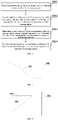
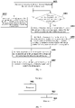
FIG. 1 is a flowchart of a stroke erasing method according to Embodiment one of the present invention; -
FIG. 2 is a schematic diagram of a boundary rectangle where a stroke is located according to Embodiment one of the present invention; -
FIG. 3 is a schematic diagram of intersection between a stroke and an erasing region according to Embodiment one of the present invention; -
FIG. 4 is a schematic diagram of intersection between a line of connection of two adjacent collection points and the erasing region according to Embodiment one of the present invention; -
FIG. 5 is a first schematic diagram of intersection between line segments of the line of connection of two adjacent collection points and the erasing region according to Embodiment one of the present invention; -
FIG. 6 is a second schematic diagram of intersection between line segments of the line of connection of two adjacent collection points and the erasing region according to Embodiment one of the present invention; -
FIG. 7 is a schematic diagram of splitting of a stroke point set into segments according to Embodiment one of the present invention; -
FIG. 8 is a flowchart of a stroke erasing method according to Embodiment two of the present invention; and -
FIG. 9 is a schematic structural diagram of a terminal according to Embodiment three of the present invention. - In order to make objects, technical schemes and advantages of the present invention clearer, the embodiments of the present invention are described in further detail below through specific embodiments in conjunction with the drawings. It is to be understood that specific embodiments described herein are intended only to interpret and not to limit the present invention.
- In some cases, a stroke erasing method is to traverse all points in each stroke to find an intersection point with an erasing region. This method provides an accurate calculation result, but requires a large amount of calculation, and is prone to stalling and no response especially when many strokes are erased at the same time, which affects user experience. In some improved algorithms, intersection points are quickly calculated with a method of equal division and point insertion of an eraser width. This method is fast in calculation, but is not accurate enough to erase edges when the eraser width is large. In order to deal with the above problem at least to some extent, the stroke erasing method according to the embodiment of the present invention further optimizes a traversing process and a process of calculating intersection points, and ensures accuracy of a calculation result while reducing the amount of calculation.
FIG. 1 illustrates a stroke erasing method according to an embodiment of the present invention, including the following steps S101 to S104. - At step S 101, an intersecting stroke on an electronic whiteboard that intersects with an erasing region is determined.
- In the embodiment of the present invention, there is a stroke on the electronic whiteboard. When an eraser is used for erasure, an erasing region of the eraser intersects with the stroke. Then, an intersecting stroke is determined by calculating intersection between the stroke and the erasing region, and non-intersecting strokes are quickly filtered out.
- Determining an intersecting stroke includes traversing each stroke on the electronic whiteboard, and calculating intersection of the erasing region with a boundary rectangle where the stroke is located, to determine the intersecting stroke. The stroke includes a bezier curve, and the erasing region includes a polygon region. In the embodiment of the present invention, each stroke refers to a bezier curve, and a boundary rectangle of the stroke is a minimum rectangle including the curve. As shown in
FIG. 2 , astroke 201 has aboundary rectangle 202. Operation is directly performed on the minimum rectangle and the erasing region of the polygon region to determine whether an overlapping region exists between the minimum rectangle and the polygon region. When there is an overlapping region, a stroke corresponding to the minimum rectangle is determined to be an intersecting stroke. As shown inFIG. 3 , assuming that there is astroke 301 and aquadrilateral erasing region 302, and an overlapping region exists between aboundary rectangle 303 corresponding to thestroke 301 and thequadrilateral erasing region 302, thestroke 301 is determined to be an intersecting stroke. - At step S102, each of collection points of the intersecting stroke is traversed to determine whether a line of connection between each two adjacent ones of the collection points intersects with the erasing region.
- It may be understood that, in the electronic whiteboard, each stroke is generated by drawing a bezier curve from points collected by a system, so that the intersecting stroke includes collection points. All the collection points are traversed. For each two adjacent collection points, a line of connection between the two collection points approximately represents a curve segment where the two points are located. Therefore, the line of connection between two points of the intersecting stroke is further filtered to determine whether a line of connection between each two adjacent ones of the collection points intersects with the erasing region, which includes:
-determining the line of connection between the two collection points to be intersected with the erasing region when at least one of the two collection points is within the erasing region, that is, when either one of the collection points is within the erasing region or the two collection points are within the erasing region. - When the two collection points are not within the erasing region and a length of the line of connection is determined to be less than a width w of the erasing region, a midpoint of the two collection points is calculated and it is determined whether the midpoint is within the erasing region; and the line of connection is determined to be intersected with the erasing region when the midpoint is within the erasing region. The width of the erasing region is a length of intersection between a horizontal line where a central point of the polygon region is located and the polygon region. For example, when the erasing region is an oblong, a width of the oblong is the width of the erasing region. As shown in
FIG. 4 , twoadjacent collection points erasing region 403 and a distance between thecollection points erasing region 403. Amidpoint 404 of thecollection points FIG. 4 is within theerasing region 403, so it is considered that a line of connection between thecollection points erasing region 403. When themidpoint 404 is not within theerasing region 403, it is considered that the line of connection between the two points does not intersect with theerasing region 403 and is filtered out. - In the embodiment of the present invention, when both the two collection points are not within the erasing region and the length of the line of connection is greater than or equal to the width of the erasing region, the line of connection is split into two first line segments based on the middle of the line of connection. When a length of each of the first segments is determined to be less than the width of the erasing region, it is determined whether a midpoint of the first line segment is within the erasing region. When the midpoint of the first line segment is within the erasing region, it is determined that the first line segment intersects with the erasing region. That is, when the length of the line of connection between two collection points is greater than or equal to the width w of the eraser, a midpoint of the two collection points is calculated. The two original collection points are split by the midpoint to obtain two first line segments with an equal length, which are a line segment from a first collection point to the midpoint and a line segment from the midpoint to a second collection point, respectively. It is determined whether each of the first line segments intersects with the erasing region. As shown in
FIG. 5 , a length of a line ofconnection 501 between two collection points is greater than a width of an erasingregion 502, and the line ofconnection 501 is split into twofirst line segments first line segments region 502, and amidpoint 505 of thefirst line segment 503 is within the erasingregion 502, it is considered that thefirst line segment 503 intersects with the erasing region. Amidpoint 506 of thefirst line segment 504 is not within the erasingregion 502, and then thefirst line segment 504 of the two collection points can be filtered out. - It is to be noted that, when the length of the first line segment is determined to be greater than or equal to the width of the erasing region, calculation of intersection is continued by means of midpoint recursion. In some embodiments, when the length of the first line segment is determined to be greater than or equal to the width of the erasing region, the first line segment is split based on the midpoint of the first line segment until a length of a second line segment after splitting is less than the width of the erasing region. The second line segment intersects with the erasing region when a midpoint of the second line segment is within the erasing region. That is, when the length of the first line segment is greater than or equal to the width w of the eraser, splitting is continued based on midpoint until the length is less than the width w of the eraser, in which case it is also determined with the midpoint whether a line of connection between two points intersects with the erasing region. For example, as shown in
FIG. 6 , a line of connection between two collection points includes twofirst line segments 601, each with a length greater than a width of an erasingregion 602. The twofirst line segments 601 are split respectively from a midpoint of two points to obtain four second line segments 603-606, and the lengths of each of the second line segments 603-606 is less than the width of the erasingregion 602. It is determined whether respective midpoints 6031-6061 of the second line segments 603-606 are within the erasingregion 602. InFIG. 6 , themidpoints region 602, so it is determined that thesecond line segments region 602, while themidpoints region 602, so thesecond line segments - At step S103, an approximate intersection point between the line of connection and the erasing region is determined by means of midpoint recursion when the line of connection intersects with the erasing region.
- It may be understood that determining that the line of connection intersects with the erasing region includes: when the line of connection where two adjacent collection points are located includes multiple line segments, determining that the line segments intersect with the erasing region. The line segments include the first line segments or second line segments described above. Approximate intersection points between the line of connection or the line segments of the line of connection and the erasing region are inserted into the collection points of the intersecting stroke. Therefore, the approximate intersection points between the line of connection or the line segments of the line of connection and the erasing region need to be determined. In some embodiments, if one of two points corresponding to the line of connection or a line segment of the line of connection, is within the erasing region, and the other point is outside the erasing region, and a length of the line of connection or the line segment of the line of connection is determined to be less than or equal to m, a midpoint of the line of connection or the line segment of the line of connection is taken as the approximate intersection point, m being less than the width of the erasing region. That is, when one of two adjacent collection points corresponding to the line of connection is within the erasing region and the other is outside the erasing region; or when the collection point and the midpoint corresponding to the first line segment are located inside and outside the erasing region, respectively; or when two midpoints corresponding to the second line segment are located inside and outside the erasing region, respectively, and a length of the line of connection or the first line segment or the second line segment is less than or equal to m, the middle of the line of connection, the midpoint of the first line segment, or the midpoint of the second line segment is taken as an approximate intersection point. After the approximate intersection point is determined, the approximate intersection point is inserted into the collection points of the intersecting stroke. The value of m may be adjusted according to a line width of a stroke. In some examples, m=5, in which case the approximate intersection point is more accurate and the calculation is faster. As shown in
FIG. 7 , assuming that a length of a line ofconnection 701 between two collection points is less than m, a midpoint 702 of the line ofconnection 701 is obtained, the midpoint 702 is taken as an approximate intersection point, and the approximate intersection point 702 is inserted between the two collection points. - At step S104, the intersecting stroke is split into segments according to the approximate intersection point, and the segments not erased by the erasing region are drawn.
- A stroke point set of the intersecting stroke is split into multiple segments at the approximate intersection point, and a point set of each segment is stored. At the same time, it is marked whether each segment is erased, and the segments not erased are drawn. As shown in
FIG. 7 , the intersecting stroke is split intoSegment 1,Segment 2, andSegment 3 according to theapproximate intersection point 701, andSegment 1 andSegment 3 are redrawn. - In the stroke erasing method according to the embodiment of the present invention, an intersecting stroke on an electronic whiteboard that intersects with an erasing region is determined; collection points of the intersecting stroke are traversed to determine whether a line of connection between each two adjacent ones of the collection points intersects with the erasing region; when the line of connection intersects with the erasing region, an approximate intersection point of the line of connection and the erasing region is determined by means of midpoint recursion; and the intersecting stroke is split into segments according to the approximate intersection point, and the segments not erased by the erasing region are drawn. Compared with the stroke erasing method in the existing technology, direct operation on a rectangle formed by line segments and the erasing region brings more accurate results. Quick intersection determination of adjacent points brings higher and more accurate calculation efficiency. The calculation of the intersection points by means of midpoint recursion provides higher and more accurate calculation efficiency.
- For ease of understanding, a stroke erasing method is illustrated with a more specific example in this embodiment. As shown in
FIG. 8 , the stroke erasing method includes the following steps S801 to S807. - At step S801, an intersecting stroke on an electronic whiteboard that intersects with an erasing region is determined.
- In the embodiment of the present invention, each stroke already existing on the whiteboard is traversed. A boundary rectangle where the stroke is located is calculated. Intersection between the rectangle and the erasing region is calculated, and non-intersecting strokes are quickly filtered out. In this way, an intersecting stroke is determined. Each stroke generally refers to a bezier curve, and the erasing region is a rectangular region.
- At step S802, each of collection points of the intersecting stroke is traversed, and it is determined that a line of connection intersects with the erasing region when at least one of two of the connection points is within the erasing region.
- Each stroke is generated by drawing a bezier curve from points collected by a system, so that the intersecting stroke includes multiple collection points. For each two adjacent collection points, a line of connection between the two collection points approximately represents a curve segment where the two points are located. If either one of the two collection points is within the erasing region, it is considered that the line of connection between the two collection points intersects with the erasing region.
- At step S803, when the two collection points are not within the erasing region, it is determined whether a length of the line of connection is less than a width of the erasing region, if yes, S804 is performed, and if no, S805 is performed.
- At step S804, a midpoint of the two collection points is calculated, and when the midpoint is within the erasing region, it is determined that the line of connection intersects with the erasing region.
- When a distance between the two collection points is less than a width w of an erasing region of an eraser, a midpoint of the two collection points is calculated. When the midpoint is within the erasing region, it is considered that the line of connection between the two collection points intersects with the erasing region, and does not intersect otherwise.
- At step S805, the line of connection is split based on the midpoint by recursion, and when a length of a line segment after splitting is less than the width of the erasing region, it is determined according to a midpoint of the line segment after splitting whether the line segment intersects with the erasing region.
- When a distance between two points is greater than or equal to the width w of the erasing region of the eraser, a midpoint of the two points is calculated. The two original points are split at the midpoint, and it is determined whether a first line segment 1 (from a first point to the midpoint) and a first line segment 2 (from the midpoint to a second point) intersect with the erasing region, respectively. The
first line segment 1 has the same length as thefirst line segment 2. When the length of thefirst line segment 1 is greater than or equal to the width w of the erasing region of the eraser, splitting is continued with a midpoint of two points, and recursive calculation is performed, until a length of each line segment after splitting is less than the width w of the erasing region of the eraser, in which case it is determined, by calculating whether a midpoint of two points is within the erasing region, whether the first line segment intersects with the erasing region. When the length of thefirst line segment 1 is less than the width w of the erasing region of the eraser, it is respectively determined whether the midpoint of thefirst line segment 1 and the midpoint of thefirst line segment 2 are within the erasing region. If yes, it indicates that thefirst line segment 1 or thefirst line segment 2 intersects with the erasing region. When the midpoint is not within the erasing region, the first line segment whose midpoint is not within the erasing region is filtered out. - At step S806, an approximate intersection point of the line of connection or the line segment after splitting and the erasing region is determined by means of midpoint recursion.
- In the embodiment of the present invention, approximate intersection points between a line of connection of two adjacent collection points or the line segment split from the line of connection meeting a preset condition and the erasing region are determined. The preset condition includes, of the two points of the line of connection or a first line segment after splitting, one being within the erasing region and the other being outside the erasing region, and a length of the line of connection or the line segment being less than or equal to a preset value. The preset value may be adjusted according to a line width of a stroke, such as 5. It is to be noted that the width of the erasing region is greater than 5 in this embodiment.
- When the length of the line of connection or the line segments after splitting is less than or equal to 5, a midpoint of the line of connection or the line segments is taken as the approximate intersection point. When the length of the line of connection or the line segment is greater than 5, a midpoint of two points is calculated, and the two points are split into two segments at the midpoint. If a first segment (from a first point to the midpoint) has one point within the erasing region and the other point outside the erasing region, the two points of the first segment are split continuously at the midpoint of the two points, and recursive calculation is performed, until a distance between the two points is less than or equal to 5, in which case the midpoint of the two points is taken as an approximate intersection point. If a second segment (from the midpoint to a second point) has one point within the erasing region and the other point outside the erasing region, an approximate intersection point is obtained by the same calculation.
- At step S807, the intersecting stroke is split into segments according to the approximate intersection point, and the segments not erased by the erasing region are drawn.
- The intersection points obtained by calculation are additionally inserted into an original point set of the stroke, and the point set of the stroke is split at an intersection point and stored in segments. Each segment is a segment. At the same time, it is marked whether each segment is erased, and segments not erased are drawn.
- In the stroke erasing method according to the embodiment of the present invention, intersection between each stroke and an erasing region is calculated, and all collection points of the stroke are traversed. For each two adjacent collection points, it is calculated whether the segment of the two adjacent collection points intersects with the erasing region, and for two points whose segment intersecting with the erasing region, an approximate intersection point between the segment and the erasing region is calculated and is inserted into an original point set. The point set of the stroke is split at the intersection point and stored in segments, and at the same time, it is marked whether each segment is erased and segments not erased are drawn. In this way, the stroke and the point set forming the stroke can be rapidly filtered multiple times, which greatly reduces the amount of calculation of stroke erasure, and at the same time, the accuracy of calculation can be adjusted according to a line width of the stroke, bringing a more accurate erasing result, improving operation efficiency of stroke erasure, and improving user experience of stroke erasure in the electronic whiteboard on the whole.
- The embodiment of the present invention provides a terminal, as shown in
FIG. 9 , including aprocessor 901, amemory 902 and acommunication bus 903. - The
communication bus 903 is configured to implement connection communication between theprocessor 901 and thememory 902. - The
processor 901 is configured to execute one or more programs stored in thememory 902, so as to perform the following steps: - determining an intersecting stroke on an electronic whiteboard that intersects with an erasing region;
- traversing each of collection points of the intersecting stroke to determine whether a line of connection between each two adjacent ones of the collection points intersects with the erasing region;
- determining, when the line of connection intersects with the erasing region, an approximate intersection point between the line of connection and the erasing region by means of midpoint recursion; and
- splitting the intersecting stroke into segments according to the approximate intersection point, and drawing the segments not erased by the erasing region.
- In the embodiment of the present invention, the determining an intersecting stroke on an electronic whiteboard that intersects with an erasing region by the
processor 901 includes: traversing each stroke on the electronic whiteboard, and calculating intersection between the erasing region and a boundary rectangle where the stroke is located, to determine the intersecting stroke, the stroke including a bezier curve, the erasing region including a polygon region. - It is to be noted that the determining whether a line of connection between each two adjacent ones of the collection points intersects with the erasing region by the
processor 901 includes: determining that the line of connection intersecting with the erasing region when at least one of the two collection points is within the erasing region. When the two collection points are not within the erasing region and a length of the line of connection is determined to be less than a width of the erasing region, a midpoint of the two collection points is calculated and it is determined whether the midpoint is within the erasing region; and it is determined that the line of connection intersects with the erasing region when the midpoint is within the erasing region. On this basis, the line of connection is split into two first line segments based on the middle of the line of connection when the length of the line of connection is greater than or equal to the width of the erasing region; when a length of each of the first line segments is determined to be less than the width of the erasing region, it is determined whether a midpoint of the first line segment is within the erasing region; and it is determined that the first line segment intersects with the erasing region when the midpoint of the first line segment is within the erasing region. When the length of the first line segment is determined to be greater than or equal to the width of the erasing region, the first line segment is split based on the midpoint of the first line segment until a length of a second line segment after splitting is less than the width of the erasing region; and it is determined that the second line segment intersects with the erasing region when a midpoint of the second line segment is within the erasing region. - For the line segment or the line of connection intersecting with the erasing region, if, of the two points corresponding to the line of connection or the line segment of the line of connection, one point is within the erasing region, and the other point is outside the erasing region, the
processor 901 further configured to: when it is determined that a length of the line of connection or the line segment of the line of connection is less than or equal to m, take a midpoint of the line of connection or the line segments of the line of connection as the approximate intersection point, m being less than the width of the erasing region; and when it is determined that the length of the line of connection or the line segment of the line of connection is greater than m, perform splitting according to the midpoint of the line of connection or the line segment of the line of connection until a length of a sub-segment after splitting is less than or equal to m, and take a midpoint of the sub-segment as the approximate intersection point. - According to some embodiments of the present invention, a computer-readable storage medium storing one or more programs is further provided, where the one or more programs, when executed by one or more processors, cause the one or more processors to perform steps of the stroke erasing method in the above embodiment.
- The computer-readable storage medium includes volatile and nonvolatile, removable and non-removable media implemented in any method or technology for storing information (such as computer-readable instructions, data structures, computer program modules or other data). The computer-readable storage medium includes, but is not limited to, a random access memory (RAM), a read-only memory (ROM), an electrically erasable programmable read-only memory (EEPROM), a flash memory or other memory technologies, a compact disc-read only memory (CD-ROM), a digital versatile disc (DVD) or other optical disc storage, a magnetic cassette, a magnetic tape, a magnetic disk storage or other magnetic storage apparatuses, or any other medium used for storing desired information and accessible to a computer.
- The embodiments of the present invention have the following beneficial effects.
- In the stroke erasing method, the terminal, and the computer-readable storage medium according to the embodiments of the present invention, an intersecting stroke on an electronic whiteboard that intersects with an erasing region is determined. Each of collection points of the intersecting stroke is traversed to determine whether a line of connection between each two adjacent ones of the collection points intersects with the erasing region. When the line of connection intersects with the erasing region, an approximate intersection point between the line of connection and the erasing region is determined by means of midpoint recursion. The intersecting stroke is split into segments according to the approximate intersection point, and the segments not erased by the erasing region are drawn. In the embodiments of the present invention, the intersecting stroke is determined directly by the strokes on the electronic whiteboard and the erased region, bringing an accurate result, and quick intersection determination of adjacent points and the calculation of the approximate intersection points by means of midpoint recursion bring higher and more accurate calculation efficiency.
- Apparently, those having ordinary in the art should understand that all or some of the steps of the method, functional modules/units in the system and the apparatus disclosed above may be implemented as software (which may be implemented using program code executable by a computing device), firmware, hardware and appropriate combinations thereof. In the hardware implementation, the division of the functional modules/units mentioned in the above description may not correspond to the division of physical components. For example, one physical component may have multiple functions, or one function or step may be executed jointly by several physical components. Some or all physical components may be implemented as software executed by processors such as digital signal processors or microcontrollers, implemented as hardware, or implemented as integrated circuits such as application specific integrated circuits.
- In addition, as is well known to those having ordinary skill in the art, the communication medium generally includes computer-readable instructions, data structures, program modules or other data in modulated data signals such as carriers or other transmission mechanisms, and may include any information delivery medium. Therefore, the present invention is not limited to any specific combination of hardware and software.
- The above are further detailed descriptions of the present invention in conjunction with specific embodiments, and it should be noted that the specific embodiments of the present invention are not limited to such descriptions. For those having ordinary skill in the art, several simple deductions or replacements may further be made without departing from the concept of the present invention, all of which should be considered within the protection scope of the present invention.
Claims (10)
- A stroke erasing method, comprising:determining an intersecting stroke on an electronic whiteboard that intersects with an erasing region;traversing each of collection points of the intersecting stroke to determine whether a line of connection between each two adjacent ones of the collection points intersects with the erasing region;determining, in response to the line of connection intersecting with the erasing region, an approximate intersection point between the line of connection and the erasing region by means of midpoint recursion; andsplitting the intersecting stroke into segments according to the approximate intersection point, and drawing the segments not erased by the erasing region.
- The stroke erasing method of claim 1, wherein determining an intersecting stroke on an electronic whiteboard that intersects with an erasing region comprises:
traversing each stroke on the electronic whiteboard, and calculating intersection between the erasing region and a boundary rectangle where the stroke is located, to determine the intersecting stroke, the stroke comprising a bezier curve, and the erasing region comprising a polygon region. - The stroke erasing method of claim 2, wherein the determining whether a line of connection between each two adjacent ones of the collection points intersects with the erasing region further comprises:
determining that the line of connection intersects with the erasing region in response to at least one of the two collection points being within the erasing region. - The stroke erasing method of claim 3, wherein the determining whether a line of connection between each two adjacent ones of the collection points intersects with the erasing region further comprises:in response to the two collection points being not within the erasing region and a length of the line of connection being determined to be less than a width of the erasing region,calculating a midpoint of the two collection points and determining whether the midpoint is within the erasing region; anddetermining that the line of connection intersects with the erasing region in response to the midpoint being within the erasing region.
- The stroke erasing method of claim 4, wherein the determining whether a line of connection between each two adjacent ones of the collection points intersects with the erasing region further comprises:splitting the line of connection into two first line segments based on the middle of the line of connection in response to the length of the line of connection being greater than or equal to the width of the erasing region;determining, in response to a length of each of the first line segments being determined to be less than the width of the erasing region, whether a midpoint of the first line segment is within the erasing region; anddetermining that the first line segment intersects with the erasing region in response to the midpoint of the first line segment being within the erasing region.
- The stroke erasing method of claim 5, wherein the determining whether a line of connection between each two adjacent ones of the collection points intersects with the erasing region further comprises:in response to the length of the first line segments being determined to be greater than or equal to the width of the erasing region, splitting the first line segment based on the midpoint of the first line segment until a length of a second line segment after splitting is less than the width of the erasing region; anddetermining that the second line segment intersects with the erasing region in response to a midpoint of the second line segment being within the erasing region.
- The stroke erasing method of any one of claims 1-6, wherein the determining an approximate intersection point between the line of connection and the erasing region by means of midpoint recursion comprises:in response to, of two points corresponding to the line of connection or a line segment of the line of connection, one point being within the erasing region, and the other point being outside the erasing region,taking a midpoint of the line of connection or the line segment of the line of connection as the approximate intersection point in response to determining a length of the line of connection or the line segment of the line of connection to be less than or equal to m, m being less than the width of the erasing region.
- The stroke erasing method of claim 7, wherein the determining an approximate intersection point between the line of connection and the erasing region by means of midpoint recursion further comprises:
in response to determining the length of the line of connection or the line segment of the line of connection to be greater than m, performing splitting according to the midpoint of the line of connection or the line segment of the line of connection until a length of a sub-line segment after splitting is less than or equal to m, and taking a midpoint of the sub-line segment as the approximate intersection point. - A terminal, comprising a processor, a memory, and a communication bus; whereinthe communication bus is configured to implement connection communication between the processor and the memory; andthe processor is configured to execute one or more programs stored in the memory to perform steps of the stroke erasing method of any one of claims 1-8.
- A computer-readable storage medium, storing one or more programs, wherein the one or more programs, when executed by one or more processors, cause the one or more processors to perform steps of the stroke erasing method of any one of claims 1-8.
Applications Claiming Priority (2)
| Application Number | Priority Date | Filing Date | Title |
|---|---|---|---|
| CN201910678118.2A CN112286424B (en) | 2019-07-25 | 2019-07-25 | Stroke erasing method, terminal and computer readable storage medium |
| PCT/CN2020/103549 WO2021013183A1 (en) | 2019-07-25 | 2020-07-22 | Stroke erase method, terminal, and computer-readable storage medium |
Publications (3)
| Publication Number | Publication Date |
|---|---|
| EP3992767A1 true EP3992767A1 (en) | 2022-05-04 |
| EP3992767A4 EP3992767A4 (en) | 2022-08-24 |
| EP3992767B1 EP3992767B1 (en) | 2024-05-01 |
Family
ID=74193254
Family Applications (1)
| Application Number | Title | Priority Date | Filing Date |
|---|---|---|---|
| EP20844552.8A Active EP3992767B1 (en) | 2019-07-25 | 2020-07-22 | Stroke erase method, terminal, and computer-readable storage medium |
Country Status (4)
| Country | Link |
|---|---|
| US (1) | US11928316B2 (en) |
| EP (1) | EP3992767B1 (en) |
| CN (1) | CN112286424B (en) |
| WO (1) | WO2021013183A1 (en) |
Families Citing this family (3)
| Publication number | Priority date | Publication date | Assignee | Title |
|---|---|---|---|---|
| CN113282214B (en) * | 2021-05-21 | 2025-02-25 | Oppo广东移动通信有限公司 | Stroke rendering method, device, storage medium and terminal |
| CN113610946B (en) * | 2021-08-03 | 2024-05-14 | 深圳市闪联信息技术有限公司 | Method for dividing drawing handwriting by using blackboard eraser function |
| CN115761056A (en) * | 2022-12-07 | 2023-03-07 | 深圳市洲明科技股份有限公司 | SVG-based shared drawing board erasing method, terminal and storage medium |
Family Cites Families (12)
| Publication number | Priority date | Publication date | Assignee | Title |
|---|---|---|---|---|
| US7551779B2 (en) * | 2005-03-17 | 2009-06-23 | Microsoft Corporation | Word or character boundary-based scratch-out gesture recognition |
| JP2007102403A (en) * | 2005-10-03 | 2007-04-19 | Dainippon Printing Co Ltd | Erase processing device, program and electronic pen form |
| CN101477694B (en) | 2008-12-02 | 2011-07-27 | 广东威创视讯科技股份有限公司 | Handwriting erasing method and apparatus |
| JP5668365B2 (en) | 2009-11-20 | 2015-02-12 | 株式会社リコー | Drawing processing system, server device, user terminal, drawing processing method, program, and recording medium |
| CN102566862B (en) * | 2010-12-21 | 2014-08-27 | 汉王科技股份有限公司 | Method and device for erasing geometric figures in interactive electronic whiteboard |
| CN103578553B (en) * | 2013-10-14 | 2016-03-30 | 江苏敏行信息技术有限公司 | A kind of vector line style fast erase method |
| JP2015172831A (en) | 2014-03-11 | 2015-10-01 | 東芝テック株式会社 | Distribution system and processing program of distribution data |
| US20180095653A1 (en) * | 2015-08-14 | 2018-04-05 | Martin Hasek | Device, method and graphical user interface for handwritten interaction |
| US9898683B2 (en) * | 2016-05-31 | 2018-02-20 | Konica Minolta Laboratory U.S.A., Inc. | Robust method for tracing lines of table |
| CN106502607B (en) * | 2016-10-19 | 2019-02-22 | 广州视睿电子科技有限公司 | Line segment erasing method and device |
| US10783322B2 (en) * | 2017-09-29 | 2020-09-22 | Microsoft Technology Licensing, Llc | Enhanced digital ink erasing |
| CN109445676B (en) * | 2018-09-11 | 2022-05-20 | 宁波思骏科技有限公司 | Method for deleting handwritten stroke information input by user on handwriting equipment |
-
2019
- 2019-07-25 CN CN201910678118.2A patent/CN112286424B/en active Active
-
2020
- 2020-07-22 US US17/629,575 patent/US11928316B2/en active Active
- 2020-07-22 EP EP20844552.8A patent/EP3992767B1/en active Active
- 2020-07-22 WO PCT/CN2020/103549 patent/WO2021013183A1/en not_active Ceased
Also Published As
| Publication number | Publication date |
|---|---|
| US11928316B2 (en) | 2024-03-12 |
| WO2021013183A1 (en) | 2021-01-28 |
| CN112286424A (en) | 2021-01-29 |
| CN112286424B (en) | 2025-04-29 |
| EP3992767B1 (en) | 2024-05-01 |
| EP3992767A4 (en) | 2022-08-24 |
| US20220276754A1 (en) | 2022-09-01 |
Similar Documents
| Publication | Publication Date | Title |
|---|---|---|
| US11928316B2 (en) | Stroke erase method, terminal, and computer-readable storage medium | |
| US20200292336A1 (en) | Vehicle track planning method, device, computer device and computer-readable storage medium | |
| US20200262447A1 (en) | Method, apparatus and server for real-time learning of travelling strategy of driverless vehicle | |
| CN111814746A (en) | Method, device, equipment and storage medium for identifying lane line | |
| CN110069961B (en) | Object detection method and device | |
| JP2020038622A (en) | Lane line tracking method and device | |
| EP4171018A1 (en) | Subtitle generation method and apparatus, and device and storage medium | |
| CN116434090B (en) | Water pollution monitoring data management method and system | |
| CN109213448B (en) | Method, device, equipment and storage medium for erasing and writing data of smart card | |
| CN106502607A (en) | Line segment erasing method and device | |
| WO2017181631A1 (en) | Method and device for processing capacity information of project file | |
| CN111739043A (en) | Parking space drawing method, device, equipment and storage medium | |
| CN118170277A (en) | Anti-shake control method, device, equipment and storage medium | |
| US20230185438A1 (en) | Interaction method of audio-video segmentation, apparatus, device and storage medium | |
| US12307702B2 (en) | Map processing method and apparatus | |
| CN107220981A (en) | Character segmentation method, device, equipment and storage medium | |
| US20220101670A1 (en) | Vehicle performance evaluation method, device and terminal | |
| CN112130739B (en) | Touch screen display frame adjusting method and device, touch screen equipment and storage medium | |
| CN117290317B (en) | A text comparison method, apparatus, device, and medium based on the diff-match-patch algorithm | |
| CN114546174B (en) | Handwriting processing method, display device and readable storage medium | |
| CN108415656B (en) | Display control method, device, medium and electronic equipment in virtual scene | |
| CN110797081B (en) | Activation area identification method and device, storage medium and electronic equipment | |
| CN116309628A (en) | Lane line recognition method and device, electronic device and computer-readable storage medium | |
| US11915443B2 (en) | Image processing method and apparatus | |
| CN107885839B (en) | Method and device for reading information in Word file |
Legal Events
| Date | Code | Title | Description |
|---|---|---|---|
| STAA | Information on the status of an ep patent application or granted ep patent |
Free format text: STATUS: THE INTERNATIONAL PUBLICATION HAS BEEN MADE |
|
| PUAI | Public reference made under article 153(3) epc to a published international application that has entered the european phase |
Free format text: ORIGINAL CODE: 0009012 |
|
| STAA | Information on the status of an ep patent application or granted ep patent |
Free format text: STATUS: REQUEST FOR EXAMINATION WAS MADE |
|
| 17P | Request for examination filed |
Effective date: 20220125 |
|
| AK | Designated contracting states |
Kind code of ref document: A1 Designated state(s): AL AT BE BG CH CY CZ DE DK EE ES FI FR GB GR HR HU IE IS IT LI LT LU LV MC MK MT NL NO PL PT RO RS SE SI SK SM TR |
|
| A4 | Supplementary search report drawn up and despatched |
Effective date: 20220722 |
|
| RIC1 | Information provided on ipc code assigned before grant |
Ipc: G06F 3/04883 20220101ALI20220718BHEP Ipc: G06F 3/04845 20220101ALI20220718BHEP Ipc: G06F 3/14 20060101ALI20220718BHEP Ipc: G06F 3/0488 20220101ALI20220718BHEP Ipc: G06F 3/0484 20220101AFI20220718BHEP |
|
| DAV | Request for validation of the european patent (deleted) | ||
| DAX | Request for extension of the european patent (deleted) | ||
| GRAP | Despatch of communication of intention to grant a patent |
Free format text: ORIGINAL CODE: EPIDOSNIGR1 |
|
| STAA | Information on the status of an ep patent application or granted ep patent |
Free format text: STATUS: GRANT OF PATENT IS INTENDED |
|
| INTG | Intention to grant announced |
Effective date: 20240129 |
|
| GRAS | Grant fee paid |
Free format text: ORIGINAL CODE: EPIDOSNIGR3 |
|
| GRAA | (expected) grant |
Free format text: ORIGINAL CODE: 0009210 |
|
| STAA | Information on the status of an ep patent application or granted ep patent |
Free format text: STATUS: THE PATENT HAS BEEN GRANTED |
|
| AK | Designated contracting states |
Kind code of ref document: B1 Designated state(s): AL AT BE BG CH CY CZ DE DK EE ES FI FR GB GR HR HU IE IS IT LI LT LU LV MC MK MT NL NO PL PT RO RS SE SI SK SM TR |
|
| REG | Reference to a national code |
Ref country code: GB Ref legal event code: FG4D |
|
| REG | Reference to a national code |
Ref country code: CH Ref legal event code: EP |
|
| REG | Reference to a national code |
Ref country code: DE Ref legal event code: R096 Ref document number: 602020030376 Country of ref document: DE |
|
| REG | Reference to a national code |
Ref country code: IE Ref legal event code: FG4D |
|
| REG | Reference to a national code |
Ref country code: LT Ref legal event code: MG9D |
|
| REG | Reference to a national code |
Ref country code: NL Ref legal event code: MP Effective date: 20240501 |
|
| PG25 | Lapsed in a contracting state [announced via postgrant information from national office to epo] |
Ref country code: IS Free format text: LAPSE BECAUSE OF FAILURE TO SUBMIT A TRANSLATION OF THE DESCRIPTION OR TO PAY THE FEE WITHIN THE PRESCRIBED TIME-LIMIT Effective date: 20240901 |
|
| PG25 | Lapsed in a contracting state [announced via postgrant information from national office to epo] |
Ref country code: BG Free format text: LAPSE BECAUSE OF FAILURE TO SUBMIT A TRANSLATION OF THE DESCRIPTION OR TO PAY THE FEE WITHIN THE PRESCRIBED TIME-LIMIT Effective date: 20240501 |
|
| PG25 | Lapsed in a contracting state [announced via postgrant information from national office to epo] |
Ref country code: FI Free format text: LAPSE BECAUSE OF FAILURE TO SUBMIT A TRANSLATION OF THE DESCRIPTION OR TO PAY THE FEE WITHIN THE PRESCRIBED TIME-LIMIT Effective date: 20240501 Ref country code: HR Free format text: LAPSE BECAUSE OF FAILURE TO SUBMIT A TRANSLATION OF THE DESCRIPTION OR TO PAY THE FEE WITHIN THE PRESCRIBED TIME-LIMIT Effective date: 20240501 |
|
| PG25 | Lapsed in a contracting state [announced via postgrant information from national office to epo] |
Ref country code: GR Free format text: LAPSE BECAUSE OF FAILURE TO SUBMIT A TRANSLATION OF THE DESCRIPTION OR TO PAY THE FEE WITHIN THE PRESCRIBED TIME-LIMIT Effective date: 20240802 |
|
| PG25 | Lapsed in a contracting state [announced via postgrant information from national office to epo] |
Ref country code: PT Free format text: LAPSE BECAUSE OF FAILURE TO SUBMIT A TRANSLATION OF THE DESCRIPTION OR TO PAY THE FEE WITHIN THE PRESCRIBED TIME-LIMIT Effective date: 20240902 |
|
| REG | Reference to a national code |
Ref country code: AT Ref legal event code: MK05 Ref document number: 1683274 Country of ref document: AT Kind code of ref document: T Effective date: 20240501 |
|
| PG25 | Lapsed in a contracting state [announced via postgrant information from national office to epo] |
Ref country code: NL Free format text: LAPSE BECAUSE OF FAILURE TO SUBMIT A TRANSLATION OF THE DESCRIPTION OR TO PAY THE FEE WITHIN THE PRESCRIBED TIME-LIMIT Effective date: 20240501 |
|
| PG25 | Lapsed in a contracting state [announced via postgrant information from national office to epo] |
Ref country code: ES Free format text: LAPSE BECAUSE OF FAILURE TO SUBMIT A TRANSLATION OF THE DESCRIPTION OR TO PAY THE FEE WITHIN THE PRESCRIBED TIME-LIMIT Effective date: 20240501 |
|
| PG25 | Lapsed in a contracting state [announced via postgrant information from national office to epo] |
Ref country code: AT Free format text: LAPSE BECAUSE OF FAILURE TO SUBMIT A TRANSLATION OF THE DESCRIPTION OR TO PAY THE FEE WITHIN THE PRESCRIBED TIME-LIMIT Effective date: 20240501 |
|
| PG25 | Lapsed in a contracting state [announced via postgrant information from national office to epo] |
Ref country code: PL Free format text: LAPSE BECAUSE OF FAILURE TO SUBMIT A TRANSLATION OF THE DESCRIPTION OR TO PAY THE FEE WITHIN THE PRESCRIBED TIME-LIMIT Effective date: 20240501 |
|
| PG25 | Lapsed in a contracting state [announced via postgrant information from national office to epo] |
Ref country code: LV Free format text: LAPSE BECAUSE OF FAILURE TO SUBMIT A TRANSLATION OF THE DESCRIPTION OR TO PAY THE FEE WITHIN THE PRESCRIBED TIME-LIMIT Effective date: 20240501 |
|
| PG25 | Lapsed in a contracting state [announced via postgrant information from national office to epo] |
Ref country code: PT Free format text: LAPSE BECAUSE OF FAILURE TO SUBMIT A TRANSLATION OF THE DESCRIPTION OR TO PAY THE FEE WITHIN THE PRESCRIBED TIME-LIMIT Effective date: 20240902 Ref country code: PL Free format text: LAPSE BECAUSE OF FAILURE TO SUBMIT A TRANSLATION OF THE DESCRIPTION OR TO PAY THE FEE WITHIN THE PRESCRIBED TIME-LIMIT Effective date: 20240501 Ref country code: NO Free format text: LAPSE BECAUSE OF FAILURE TO SUBMIT A TRANSLATION OF THE DESCRIPTION OR TO PAY THE FEE WITHIN THE PRESCRIBED TIME-LIMIT Effective date: 20240801 Ref country code: NL Free format text: LAPSE BECAUSE OF FAILURE TO SUBMIT A TRANSLATION OF THE DESCRIPTION OR TO PAY THE FEE WITHIN THE PRESCRIBED TIME-LIMIT Effective date: 20240501 Ref country code: LV Free format text: LAPSE BECAUSE OF FAILURE TO SUBMIT A TRANSLATION OF THE DESCRIPTION OR TO PAY THE FEE WITHIN THE PRESCRIBED TIME-LIMIT Effective date: 20240501 Ref country code: IS Free format text: LAPSE BECAUSE OF FAILURE TO SUBMIT A TRANSLATION OF THE DESCRIPTION OR TO PAY THE FEE WITHIN THE PRESCRIBED TIME-LIMIT Effective date: 20240901 Ref country code: HR Free format text: LAPSE BECAUSE OF FAILURE TO SUBMIT A TRANSLATION OF THE DESCRIPTION OR TO PAY THE FEE WITHIN THE PRESCRIBED TIME-LIMIT Effective date: 20240501 Ref country code: GR Free format text: LAPSE BECAUSE OF FAILURE TO SUBMIT A TRANSLATION OF THE DESCRIPTION OR TO PAY THE FEE WITHIN THE PRESCRIBED TIME-LIMIT Effective date: 20240802 Ref country code: FI Free format text: LAPSE BECAUSE OF FAILURE TO SUBMIT A TRANSLATION OF THE DESCRIPTION OR TO PAY THE FEE WITHIN THE PRESCRIBED TIME-LIMIT Effective date: 20240501 Ref country code: ES Free format text: LAPSE BECAUSE OF FAILURE TO SUBMIT A TRANSLATION OF THE DESCRIPTION OR TO PAY THE FEE WITHIN THE PRESCRIBED TIME-LIMIT Effective date: 20240501 Ref country code: BG Free format text: LAPSE BECAUSE OF FAILURE TO SUBMIT A TRANSLATION OF THE DESCRIPTION OR TO PAY THE FEE WITHIN THE PRESCRIBED TIME-LIMIT Effective date: 20240501 Ref country code: AT Free format text: LAPSE BECAUSE OF FAILURE TO SUBMIT A TRANSLATION OF THE DESCRIPTION OR TO PAY THE FEE WITHIN THE PRESCRIBED TIME-LIMIT Effective date: 20240501 Ref country code: RS Free format text: LAPSE BECAUSE OF FAILURE TO SUBMIT A TRANSLATION OF THE DESCRIPTION OR TO PAY THE FEE WITHIN THE PRESCRIBED TIME-LIMIT Effective date: 20240801 |
|
| PG25 | Lapsed in a contracting state [announced via postgrant information from national office to epo] |
Ref country code: DK Free format text: LAPSE BECAUSE OF FAILURE TO SUBMIT A TRANSLATION OF THE DESCRIPTION OR TO PAY THE FEE WITHIN THE PRESCRIBED TIME-LIMIT Effective date: 20240501 |
|
| PG25 | Lapsed in a contracting state [announced via postgrant information from national office to epo] |
Ref country code: EE Free format text: LAPSE BECAUSE OF FAILURE TO SUBMIT A TRANSLATION OF THE DESCRIPTION OR TO PAY THE FEE WITHIN THE PRESCRIBED TIME-LIMIT Effective date: 20240501 |
|
| PG25 | Lapsed in a contracting state [announced via postgrant information from national office to epo] |
Ref country code: CZ Free format text: LAPSE BECAUSE OF FAILURE TO SUBMIT A TRANSLATION OF THE DESCRIPTION OR TO PAY THE FEE WITHIN THE PRESCRIBED TIME-LIMIT Effective date: 20240501 |
|
| PG25 | Lapsed in a contracting state [announced via postgrant information from national office to epo] |
Ref country code: RO Free format text: LAPSE BECAUSE OF FAILURE TO SUBMIT A TRANSLATION OF THE DESCRIPTION OR TO PAY THE FEE WITHIN THE PRESCRIBED TIME-LIMIT Effective date: 20240501 Ref country code: SK Free format text: LAPSE BECAUSE OF FAILURE TO SUBMIT A TRANSLATION OF THE DESCRIPTION OR TO PAY THE FEE WITHIN THE PRESCRIBED TIME-LIMIT Effective date: 20240501 |
|
| PG25 | Lapsed in a contracting state [announced via postgrant information from national office to epo] |
Ref country code: SM Free format text: LAPSE BECAUSE OF FAILURE TO SUBMIT A TRANSLATION OF THE DESCRIPTION OR TO PAY THE FEE WITHIN THE PRESCRIBED TIME-LIMIT Effective date: 20240501 |
|
| PG25 | Lapsed in a contracting state [announced via postgrant information from national office to epo] |
Ref country code: SM Free format text: LAPSE BECAUSE OF FAILURE TO SUBMIT A TRANSLATION OF THE DESCRIPTION OR TO PAY THE FEE WITHIN THE PRESCRIBED TIME-LIMIT Effective date: 20240501 Ref country code: SK Free format text: LAPSE BECAUSE OF FAILURE TO SUBMIT A TRANSLATION OF THE DESCRIPTION OR TO PAY THE FEE WITHIN THE PRESCRIBED TIME-LIMIT Effective date: 20240501 Ref country code: RO Free format text: LAPSE BECAUSE OF FAILURE TO SUBMIT A TRANSLATION OF THE DESCRIPTION OR TO PAY THE FEE WITHIN THE PRESCRIBED TIME-LIMIT Effective date: 20240501 Ref country code: EE Free format text: LAPSE BECAUSE OF FAILURE TO SUBMIT A TRANSLATION OF THE DESCRIPTION OR TO PAY THE FEE WITHIN THE PRESCRIBED TIME-LIMIT Effective date: 20240501 Ref country code: DK Free format text: LAPSE BECAUSE OF FAILURE TO SUBMIT A TRANSLATION OF THE DESCRIPTION OR TO PAY THE FEE WITHIN THE PRESCRIBED TIME-LIMIT Effective date: 20240501 Ref country code: CZ Free format text: LAPSE BECAUSE OF FAILURE TO SUBMIT A TRANSLATION OF THE DESCRIPTION OR TO PAY THE FEE WITHIN THE PRESCRIBED TIME-LIMIT Effective date: 20240501 |
|
| REG | Reference to a national code |
Ref country code: DE Ref legal event code: R097 Ref document number: 602020030376 Country of ref document: DE |
|
| PG25 | Lapsed in a contracting state [announced via postgrant information from national office to epo] |
Ref country code: IT Free format text: LAPSE BECAUSE OF FAILURE TO SUBMIT A TRANSLATION OF THE DESCRIPTION OR TO PAY THE FEE WITHIN THE PRESCRIBED TIME-LIMIT Effective date: 20240501 Ref country code: MC Free format text: LAPSE BECAUSE OF FAILURE TO SUBMIT A TRANSLATION OF THE DESCRIPTION OR TO PAY THE FEE WITHIN THE PRESCRIBED TIME-LIMIT Effective date: 20240501 |
|
| REG | Reference to a national code |
Ref country code: CH Ref legal event code: PL |
|
| PLBE | No opposition filed within time limit |
Free format text: ORIGINAL CODE: 0009261 |
|
| STAA | Information on the status of an ep patent application or granted ep patent |
Free format text: STATUS: NO OPPOSITION FILED WITHIN TIME LIMIT |
|
| PG25 | Lapsed in a contracting state [announced via postgrant information from national office to epo] |
Ref country code: LU Free format text: LAPSE BECAUSE OF NON-PAYMENT OF DUE FEES Effective date: 20240722 |
|
| PG25 | Lapsed in a contracting state [announced via postgrant information from national office to epo] |
Ref country code: LU Free format text: LAPSE BECAUSE OF NON-PAYMENT OF DUE FEES Effective date: 20240722 |
|
| 26N | No opposition filed |
Effective date: 20250204 |
|
| PG25 | Lapsed in a contracting state [announced via postgrant information from national office to epo] |
Ref country code: SI Free format text: LAPSE BECAUSE OF FAILURE TO SUBMIT A TRANSLATION OF THE DESCRIPTION OR TO PAY THE FEE WITHIN THE PRESCRIBED TIME-LIMIT Effective date: 20240501 Ref country code: CH Free format text: LAPSE BECAUSE OF NON-PAYMENT OF DUE FEES Effective date: 20240731 Ref country code: BE Free format text: LAPSE BECAUSE OF NON-PAYMENT OF DUE FEES Effective date: 20240731 |
|
| REG | Reference to a national code |
Ref country code: BE Ref legal event code: MM Effective date: 20240731 |
|
| PG25 | Lapsed in a contracting state [announced via postgrant information from national office to epo] |
Ref country code: IE Free format text: LAPSE BECAUSE OF NON-PAYMENT OF DUE FEES Effective date: 20240722 |
|
| PG25 | Lapsed in a contracting state [announced via postgrant information from national office to epo] |
Ref country code: SE Free format text: LAPSE BECAUSE OF FAILURE TO SUBMIT A TRANSLATION OF THE DESCRIPTION OR TO PAY THE FEE WITHIN THE PRESCRIBED TIME-LIMIT Effective date: 20240501 |
|
| PGFP | Annual fee paid to national office [announced via postgrant information from national office to epo] |
Ref country code: DE Payment date: 20250722 Year of fee payment: 6 |
|
| PGFP | Annual fee paid to national office [announced via postgrant information from national office to epo] |
Ref country code: GB Payment date: 20250722 Year of fee payment: 6 |
|
| PGFP | Annual fee paid to national office [announced via postgrant information from national office to epo] |
Ref country code: FR Payment date: 20250725 Year of fee payment: 6 |
|
| PG25 | Lapsed in a contracting state [announced via postgrant information from national office to epo] |
Ref country code: CY Free format text: LAPSE BECAUSE OF FAILURE TO SUBMIT A TRANSLATION OF THE DESCRIPTION OR TO PAY THE FEE WITHIN THE PRESCRIBED TIME-LIMIT; INVALID AB INITIO Effective date: 20200722 |
|
| PG25 | Lapsed in a contracting state [announced via postgrant information from national office to epo] |
Ref country code: HU Free format text: LAPSE BECAUSE OF FAILURE TO SUBMIT A TRANSLATION OF THE DESCRIPTION OR TO PAY THE FEE WITHIN THE PRESCRIBED TIME-LIMIT; INVALID AB INITIO Effective date: 20200722 |