EP3992740A1 - Prediction system - Google Patents
Prediction system Download PDFInfo
- Publication number
- EP3992740A1 EP3992740A1 EP20833158.7A EP20833158A EP3992740A1 EP 3992740 A1 EP3992740 A1 EP 3992740A1 EP 20833158 A EP20833158 A EP 20833158A EP 3992740 A1 EP3992740 A1 EP 3992740A1
- Authority
- EP
- European Patent Office
- Prior art keywords
- operation state
- attribute information
- target device
- history
- filter condition
- Prior art date
- Legal status (The legal status is an assumption and is not a legal conclusion. Google has not performed a legal analysis and makes no representation as to the accuracy of the status listed.)
- Granted
Links
Images



Classifications
-
- G—PHYSICS
- G05—CONTROLLING; REGULATING
- G05B—CONTROL OR REGULATING SYSTEMS IN GENERAL; FUNCTIONAL ELEMENTS OF SUCH SYSTEMS; MONITORING OR TESTING ARRANGEMENTS FOR SUCH SYSTEMS OR ELEMENTS
- G05B23/00—Testing or monitoring of control systems or parts thereof
- G05B23/02—Electric testing or monitoring
-
- G—PHYSICS
- G05—CONTROLLING; REGULATING
- G05B—CONTROL OR REGULATING SYSTEMS IN GENERAL; FUNCTIONAL ELEMENTS OF SUCH SYSTEMS; MONITORING OR TESTING ARRANGEMENTS FOR SUCH SYSTEMS OR ELEMENTS
- G05B17/00—Systems involving the use of models or simulators of said systems
- G05B17/02—Systems involving the use of models or simulators of said systems electric
-
- G—PHYSICS
- G05—CONTROLLING; REGULATING
- G05B—CONTROL OR REGULATING SYSTEMS IN GENERAL; FUNCTIONAL ELEMENTS OF SUCH SYSTEMS; MONITORING OR TESTING ARRANGEMENTS FOR SUCH SYSTEMS OR ELEMENTS
- G05B23/00—Testing or monitoring of control systems or parts thereof
- G05B23/02—Electric testing or monitoring
- G05B23/0205—Electric testing or monitoring by means of a monitoring system capable of detecting and responding to faults
- G05B23/0218—Electric testing or monitoring by means of a monitoring system capable of detecting and responding to faults characterised by the fault detection method dealing with either existing or incipient faults
- G05B23/0224—Process history based detection method, e.g. whereby history implies the availability of large amounts of data
-
- G—PHYSICS
- G05—CONTROLLING; REGULATING
- G05B—CONTROL OR REGULATING SYSTEMS IN GENERAL; FUNCTIONAL ELEMENTS OF SUCH SYSTEMS; MONITORING OR TESTING ARRANGEMENTS FOR SUCH SYSTEMS OR ELEMENTS
- G05B23/00—Testing or monitoring of control systems or parts thereof
- G05B23/02—Electric testing or monitoring
- G05B23/0205—Electric testing or monitoring by means of a monitoring system capable of detecting and responding to faults
- G05B23/0218—Electric testing or monitoring by means of a monitoring system capable of detecting and responding to faults characterised by the fault detection method dealing with either existing or incipient faults
- G05B23/0224—Process history based detection method, e.g. whereby history implies the availability of large amounts of data
- G05B23/024—Quantitative history assessment, e.g. mathematical relationships between available data; Functions therefor; Principal component analysis [PCA]; Partial least square [PLS]; Statistical classifiers, e.g. Bayesian networks, linear regression or correlation analysis; Neural networks
-
- G—PHYSICS
- G05—CONTROLLING; REGULATING
- G05B—CONTROL OR REGULATING SYSTEMS IN GENERAL; FUNCTIONAL ELEMENTS OF SUCH SYSTEMS; MONITORING OR TESTING ARRANGEMENTS FOR SUCH SYSTEMS OR ELEMENTS
- G05B23/00—Testing or monitoring of control systems or parts thereof
- G05B23/02—Electric testing or monitoring
- G05B23/0205—Electric testing or monitoring by means of a monitoring system capable of detecting and responding to faults
- G05B23/0218—Electric testing or monitoring by means of a monitoring system capable of detecting and responding to faults characterised by the fault detection method dealing with either existing or incipient faults
- G05B23/0243—Electric testing or monitoring by means of a monitoring system capable of detecting and responding to faults characterised by the fault detection method dealing with either existing or incipient faults model based detection method, e.g. first-principles knowledge model
- G05B23/0254—Electric testing or monitoring by means of a monitoring system capable of detecting and responding to faults characterised by the fault detection method dealing with either existing or incipient faults model based detection method, e.g. first-principles knowledge model based on a quantitative model, e.g. mathematical relationships between inputs and outputs; functions: observer, Kalman filter, residual calculation, Neural Networks
-
- G—PHYSICS
- G06—COMPUTING OR CALCULATING; COUNTING
- G06N—COMPUTING ARRANGEMENTS BASED ON SPECIFIC COMPUTATIONAL MODELS
- G06N3/00—Computing arrangements based on biological models
- G06N3/02—Neural networks
- G06N3/04—Architecture, e.g. interconnection topology
- G06N3/044—Recurrent networks, e.g. Hopfield networks
- G06N3/0442—Recurrent networks, e.g. Hopfield networks characterised by memory or gating, e.g. long short-term memory [LSTM] or gated recurrent units [GRU]
-
- G—PHYSICS
- G06—COMPUTING OR CALCULATING; COUNTING
- G06N—COMPUTING ARRANGEMENTS BASED ON SPECIFIC COMPUTATIONAL MODELS
- G06N3/00—Computing arrangements based on biological models
- G06N3/02—Neural networks
- G06N3/08—Learning methods
- G06N3/09—Supervised learning
-
- G—PHYSICS
- G06—COMPUTING OR CALCULATING; COUNTING
- G06N—COMPUTING ARRANGEMENTS BASED ON SPECIFIC COMPUTATIONAL MODELS
- G06N3/00—Computing arrangements based on biological models
- G06N3/02—Neural networks
- G06N3/04—Architecture, e.g. interconnection topology
- G06N3/044—Recurrent networks, e.g. Hopfield networks
Definitions
- Certain embodiments of the invention relate to a prediction system that predicts an operation state of a target device.
- a system for predicting the future behavior of a target device and a component has been proposed based on data on an operation of a target device such as a plant.
- a characteristic change prediction system for generating a neural circuit model by learning information on changes in the characteristics of various components in a plurality of plants over time, and predicting a future characteristic change pattern of the component over time based on the similarity with each of a plurality of characteristic change patterns over time is disclosed.
- a system in which a similar plant is selected from a plurality of plants and a specific performance index is monitored from operation data is disclosed.
- the future behavior of the target device such as a plant may be significantly affected not only by the past operation state but also by factors such as the specifications of the target device and the environment in which the target device is placed. It can be said that these factors are information indicating a category to which the target device belongs when the target device is classified according to various criteria, that is, attribute information.
- an object of the embodiments of the invention is to provide a prediction system capable of predicting an operation state of a target device in the future in consideration of attribute information of the target device.
- a prediction system including a storage unit that stores a history of an operation state of each of a plurality of target devices and attribute information indicating an attribute of each of the plurality of target devices; a first acquisition unit that acquires an attribute information filter condition in which at least one attribute information included in attribute information of a prediction target device is specified; a second acquisition unit that acquires an operation state filter condition in which at least one operation state included in a history of an operation state of the prediction target device is specified; an extraction unit that extracts a history of an operation state of a target device satisfying the attribute information filter condition and the operation state filter condition of the plurality of target devices, with reference to the storage unit; and an estimating unit that predicts the operation state of the prediction target device based on the extracted history of the operation state.
- the history of the operation state of the target device that satisfies the attribute information filter condition specifying the attribute information of the target device is extracted from the history of the operation state of each of the plurality of target devices, and the operation state of the prediction target device is predicted based on the history of the operation state. Therefore, it is possible to predict the future of the operation state in consideration of the attribute information of the target device.
- a prediction system capable of predicting an operation state of a target device in the future in consideration of attribute information of the target device.
- Fig. 1 is a schematic diagram illustrating an example of a configuration of a prediction system 1 according to the embodiments of the invention.
- the prediction system 1 includes a server 10 and at least one plant 20.
- the plant 20 is an example of a "target device".
- the type of the plant 20 is not particularly limited, and may include an oil plant, a chemical plant, a pharmaceutical plant, a food plant, a paper manufacturing plant, and the like.
- the elements constituting the plant 20 are not particularly limited, and may include storage equipment for fuel and raw materials, equipment that uses fuel and raw materials, or treats and processes fuel and raw materials, and a piping system connecting each element.
- the target device to which the prediction system 1 can be applied is not limited to various plants and may be any device such as an industrial machine.
- each plant 20 is connected to each other so as to be able to communicate with each other via a communication network such as Internet.
- a communication network such as Internet.
- each plant 20 may be referred to as “plant 20A”, “plant 20B”, and the like, and when each plant 20 is generically referred to, each plant 20 may be simply referred to as "plant 20".
- the server 10 is an example of an information processing device that manages a history of an operation state (operation state history) of each plant 20.
- the server 10 is configured to include, for example, one information processing device, and the server 10 may be configured to include a plurality of information processing devices.
- the information processing device is a device capable of executing various types of information processing, such as a computer provided with a processor and a storage area. Each part illustrated in Fig. 1 can be realized, for example, by using a storage area or by executing a program stored in the storage area by a processor.
- the server 10 includes, for example, a server communication unit 11, an operation unit 12, a display unit 13, a storage unit 14, and a processing unit 15.
- the server communication unit 11 includes a communication interface circuit for connecting the server 10 to the communication network.
- the server communication unit 11 supplies data such as a history of an operation state (operation state history) received from each plant 20 to the processing unit 15.
- the operation unit 12 may be any device as long as the server 10 can be operated, and is, for example, a touch panel, a key button, or the like.
- the user can input characters, numbers, symbols, and the like using the operation unit 12.
- the operation unit 12 When the operation unit 12 is operated by the user, the operation unit 12 generates a signal corresponding to the operation. The generated signal is supplied to the processing unit 15 as a user's instruction.
- the display unit 13 may be any device as long as the display unit 13 can display a picture, an image, or the like, and is, for example, a liquid crystal display, an organic electro-luminescence (EL) display, or the like.
- the display unit 13 displays a picture corresponding to picture data supplied from the processing unit 15, an image corresponding to image data, and the like.
- the storage unit 14 includes, for example, at least one of a semiconductor memory, a magnetic disk device, and an optical disk device.
- the storage unit 14 stores a driver program, an operating system program, an application program, data, and the like used for processing by the processing unit 15.
- the storage unit 14 stores a communication device driver program or the like that controls the server communication unit 11 as a driver program.
- the various programs may be installed in the storage unit 14 from a computer-readable portable recording medium such as a CD-ROM or a DVD-ROM using a known setup program or the like.
- the storage unit 14 stores, as data, an attribute information table, an operation state history table, and the like, which will be described later.
- the storage unit 14 stores display data of various screens as data.
- the storage unit 14 temporarily stores data related to predetermined processing.
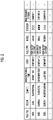
- Fig. 2 is a table illustrating an example of an attribute information table.
- the attribute information table is a table for managing attribute information for each plant.
- the attribute information of the plant 20 is, for example, information indicating a category (attribute) to which the plant 20 belongs when the plant 20 is classified according to various criteria.
- the "attribute” may be referred to as an "external state", an "incidental state”, an “external incidental state", or the like.
- attribute information of the plant 20 such as "plant ID”, “region”, “climate”, “manufacturing time”, “user”, “fuel type”, “model”, “designer”, “maintenance person”, and the like is recorded.
- the "plant ID” is identification information (ID) for identifying the plant 20.
- the "region” is information indicating the region where the plant 20 is installed.
- the “region” is information indicating the climate of the region where the plant 20 is installed.
- the “manufacturing time” is information indicating the time when the plant 20 was manufactured, and may be expressed by, for example, a year, a year and month, a year, month, and date, or the like.
- the "model” is a type of the plant 20 as a machine, and for example, the model, method, and type, and "designer” are information indicating a person (individual, company, and the like) who designed the plant 20.
- the "maintenance person” is information indicating a person (individual, company, and the like) who performs maintenance of the plant 20.
- the attribute information table is not limited to the above-described item, and may include other attribute information.
- Fig. 3 is a graph illustrating an example of an operation state history table.
- the operation state history table is a table for managing the operation state history for each plant 20.
- the history of the operation state is represented by a plurality of rectangular cells C for each plant.
- the horizontal axis indicates an elapsed time from a reference time.
- the reference time can be randomly set by the administrator or the like, and may be, for example, the start of operation, the start-up of the plant 20, or the like (including restart after a pause period for inspection, in addition to initial start-up).
- each cell C indicates the operation state of the plant 20 in the elapsed time (each cell C may be at one time point or may be a period having a predetermined width), and the type of the operation state is distinguished by the pattern in the cell C.
- the length of time possessed by one cell C can be randomly set in units of, for example, seconds, minutes, hours, days, weeks, and the like.
- the operation states are not limited to these, and may include, for example, normal operation, an accident occurrence (during accidents such as fuel shortage, appearance of foreign matter, temperature rise, temperature drop, cooler trip, fuel system trip, blast, and blackout), an alarm occurrence (during other alarms such as balancing shoot level alarm), an operation stop, and an occurrence of any other event.
- the processing unit 15 includes one or more processors and peripheral circuits thereof.
- the processing unit 15 comprehensively controls the overall operation of the server 10, and is, for example, a central processing unit (CPU).
- the processing unit 15 controls the operation of the server communication unit 11 and the like so that various processing of the server 10 is executed by an appropriate procedure based on the program and the like stored in the storage unit 14.
- the processing unit 15 executes processing based on a program (operating system program, driver program, application program, and the like) stored in the storage unit 14.
- the processing unit 15 can execute a plurality of programs (application programs and the like) in parallel.
- the processing unit 15 includes a collection portion 151, a first acquisition unit 152a, a second acquisition unit 152b, an extraction unit 153, an estimating unit 154, a display processing unit 155, and the like.
- Each of these units included in the processing unit 15 is a functional module mounted by a program executed on the processor included in the processing unit 15.
- each of these units included in the processing unit 15 may be mounted on the server 2 as an independent integrated circuit, microprocessor, or firmware.
- the collection portion 151 collects (receives) the operation state history of the plant 20 from each plant 20 and records the operation state history in the operation state history table stored in the storage unit 14 or the like.
- the timing at which the collection or recording processing of the collection portion 151 is executed is not particularly limited, and may be, for example, a predetermined periodic or aperiodic timing, or when an administrator or the like inputs a command for executing the processing via the operation unit 12.
- a reception unit 152 receives, for example, various filter conditions input by the user via the operation unit 12.
- the filter condition is a condition that the plant 20 or the operation state history of the plant 20 is required to satisfy in order to extract (filter) a desired operation state history from the operation state history table.
- the first acquisition unit 152a acquires the attribute information filter condition, which is a condition related to the attribute information of the plant 20.
- the attribute information filter condition is a condition that the plant 20 is required to satisfy in order to extract (filter) a desired operation state history from the operation state history table, and is a condition in which at least one attribute information included in the attribute information of the prediction target device is specified.
- the attribute information included in the attribute information filter condition may be, for example, the attribute information listed in the above description of Fig. 2 described above, or any other attribute information.
- the first acquisition unit 152a acquires the attribute information filter condition, for example, by receiving the attribute information filter condition input by the user via the operation unit 12.
- the second acquisition unit 152b acquires the operation state filter condition which is a condition related to the operation state of the plant 20.
- the operation state filter condition is a condition that the operation state history of the plant 20 is required to satisfy in order to extract (filter) a desired operation state history from the operation state history table.
- the operation state filter condition at least one operation state included in the operation state history of the prediction target device is specified.
- the order of occurrence of each operation state may be specified.
- the extraction unit 153 extracts the operation state history of the plant 20 that satisfies the attribute information filter condition received by the first acquisition unit 152a and the operation state filter condition received by the second acquisition unit 152b with reference to the storage unit 14.
- the extraction unit 153 may extract only when the duration time of the operation state (when the operation state is intermittent, the duration time may be the total time of the history of each operation state) specified as the operation state filter condition is equal to or longer than a predetermined threshold.
- the estimating unit 154 predicts the operation state of the prediction target device (plant) based on the operation state history extracted by the extraction unit 153.
- a method of predicting the operation state by the estimating unit 154 is not particularly limited, and may be, for example, a prediction by statistical analysis, a prediction by a probability density function, a prediction based on Bayesian theory, or the like. More specifically, for example, the estimating unit 154 may calculate the probability of occurrence of the operation state for each hour by statistically analyzing the operation state history extracted by the extraction unit 153 (for example, the extracted operation state history is aggregated for each hour and then normalized). Depending on the probability of occurrence, it is possible to predict the operation state of the prediction target device (plant) at a certain point in the future.
- the estimating unit 154 may execute machine learning using the operation state history extracted by the extraction unit 153 as learning data to generate a learning model, and input the history of the operation state of the prediction target device (plant) into the learning model to output the future operation state of the prediction target device. More specifically, for example, the estimating unit 154 may generate a learning model that inputs time-series data of the operation state history and outputs the future operation state by learning the recurrent neural network (RNN) using the operation state history extracted by the extraction unit 153 as learning data. Depending on the future operation state, it is possible to predict the operation state of the prediction target device (plant) at a certain point in the future.
- RNN recurrent neural network
- the display processing unit 155 causes the display unit 13 to display various screens based on the display data of the various screens stored in the storage unit 14.
- the plant 20 includes an operating unit 21, various sensors 22, a measurement control system 23, and a plant communication unit 24.
- the operating unit 21 includes a main device constituting the plant 20, and includes, for example, various modules such as a combustion chamber and a heat exchange chamber, a piping system connecting each module, and the like.
- the sensor 22 is installed in each place in the operating unit 21, detect various physical quantities of the operating unit 21, and supply the detection results to the measurement control system 23.
- the measurement control system 23 generates an operation state history based on the detection result supplied from the sensor 22. Specifically, the measurement control system 23 analyzes the detection result supplied from the sensor 22 to determine the operation state of the operating unit 21 on which the sensor 22 is installed, and then generates an operation state history which is a time-series change in the determined operation state.
- the measurement control system 23 transmits the operation state history of the operating unit 21 to the server 10 via the plant communication unit 24.
- Fig. 4 is a flow chart illustrating an example of an operation flow by the prediction system 1 according to the embodiment.
- Fig. 5 is a view illustrating an example of a screen 500 displayed on the display unit 13.
- Fig. 6 is a view illustrating an example of a screen 600 displayed on the display unit 13.
- the individual plants 20 may be referred to as a "plant A", a "plant B", and the like.
- the collection portion 151 of the server 10 collects the operation state history of the plant 20 from each plant 20 in advance and records the operation state history in the operation state history table stored in the storage unit 14.
- the first acquisition unit 152a of the server 10 acquires the attribute information filter condition. Specifically, for example, the first acquisition unit 152a acquires the attribute information filter condition by receiving the input of the attribute information filter condition in response to the operation of the operation unit 12 by the user.
- the display processing unit 155 of the server 10 causes the display unit 13 to display the screen 500 illustrated in Fig. 5 , for example, based on the display data stored in the storage unit 14.
- the screen 500 includes a display unit 501 for the attribute information filter condition, a display unit 502 for the operation state filter condition, and a display unit 503 for the operation state history of the extracted plant 20.
- the display unit 501 displays the content of the attribute information filter condition acquired by the first acquisition unit 152a.
- the display unit 501 displays the attribute information filter conditions in which the region is "cold area", the fuel is "high water content”, and the model is "small".
- the extraction unit 153 refers to the attribute information table stored in the storage unit 14, identifies the plant 20 that satisfies the attribute information filter condition acquired in S100, and then extracts the operation state history of the specified plant 20 from the operation state history table.
- the second acquisition unit 152b of the server 10 receives the designation of the plant 20 as the prediction target device in response to the operation of the operation unit 12 by the user. Specifically, the second acquisition unit 152b receives input of information for specifying the plant 20 specified by the user as the prediction target device (for example, name of the plant 20, identification information, and the like).
- the second acquisition unit 152b of the server 10 acquires the operation state filter condition by generating the operation state filter condition based on the operation state history of the specified plant 20 with reference to the operation state history table stored in the storage unit 14. For example, the second acquisition unit 152b may select at least one operation state included in the history of the operation state of the plant 20 as the prediction target device, and use the selected operation state as the operation state filter condition. In particular, the second acquisition unit 152b may use all the operation states included in the history of the operation state of the plant 20 as the prediction target device as the operation state filter condition.
- the display unit 502 of the screen 500 displays the content of the operation state filter condition generated by the second acquisition unit 152b.
- the display unit 502 displays the content of the operation state filter condition acquired by the second acquisition unit 152b.
- " operation state ⁇ ", "operation state X”, and "operation state ⁇ " are displayed on the display unit 502 as operation state filter conditions. This is because the operation state history of the plant X includes the history of "operation state ⁇ ", "operation state X", and "operation state ⁇ ", respectively.
- the extraction unit 153 extracts the operation state history that satisfies the operation state filter condition generated in S103 from the operation state history extracted in S101.
- the display unit 503 of the screen 500 displays the operation state history of the plant 20 extracted as a plant satisfying the attribute information filter condition and the operation state filter condition (specifically, the operation state history of plant A, plant C, plant E, and plant F).
- the estimating unit 154 predicts the operation state of the prediction target device based on the operation state history of the plant 20 extracted in S101. Specifically, for example, the estimating unit 154 may calculate the probability of occurrence of the operation state for each hour by statistically analyzing the extracted operation state history. Alternatively, for example, the estimating unit 154 may execute machine learning using the operation state history extracted by the extraction unit 153 as learning data to generate a learning model, and input the history of the operation state of the prediction target device (plant) into the learning model to generate an output indicating the future operation state of the prediction target device (plant).
- the display processing unit 155 causes the display unit 13 to display the prediction result by the estimating unit 154, and the operation processing of the prediction system 1 is terminated.
- Fig. 6A is an example of a screen 600 illustrating a prediction result displayed on the display unit 13 by the display processing unit 155 when the estimating unit 154 calculates the probability of occurrence of an operation state.
- the screen 600 includes a display unit 601 for the probability of occurrence of the operation state calculated by the estimating unit 154 and a display unit 602 for the operation state history of the prediction target device.
- the display unit 601 displays the time-series change of the probability of occurrence of each operation state calculated by the estimating unit 154.
- Fig. 6A is an example of a screen 600 illustrating a prediction result displayed on the display unit 13 by the display processing unit 155 when the estimating unit 154 calculates the probability of occurrence of an operation state.
- the screen 600 includes a display unit 601 for the probability of occurrence of the operation state calculated by the estimating unit 154 and a display unit 602 for the operation state history of the prediction target device.
- the display unit 601 displays the time-series change of the probability of occurrence of
- the display unit 602 displays the operation state history of the plant X, which is a prediction target device of the operation state. Specifically, the display unit 602 displays the operation state history of the plant X from the start of operation to the lapse of time T1. Here, after the time T1, it is possible to predict the specific operation state of the plant X with the probability of occurrence based on the probability of occurrence displayed on the display unit 601. In the example illustrated in Fig. 6A , in the plant X in the future time T2 (> T1), the probability of becoming the operation state ⁇ is P ⁇ (T2), and the probability of becoming the operation state ⁇ is P ⁇ (T2).
- Fig. 6B is an example of a screen 700 illustrating a prediction result displayed on the display unit 13 by the display processing unit 155 when the estimating unit 154 makes a prediction by a learning model by machine learning.
- the screen 700 includes a display unit 701 for time-series change of the operation state of the plant X, which is a prediction target device.
- the display unit 701 displays the history of the operation state of the plant X up to the current time T1.
- the history of the operation state of the plant X up to the current time T1 is the learning data in the machine learning executed by the estimating unit 154.
- the display unit 701 displays the future operation state as an output obtained by inputting the operation state history of the plant X into the learning model generated by the estimating unit 154 using the learning data.
- the second acquisition unit 152b receives the designation of the plant 20 as the prediction target device (S102), and then generates the operation state filter condition based on the operation state history of the specified plant 20 (S103) to acquire the operation state filter condition.
- the second acquisition unit 152b may acquire the operation state filter condition input by the user, for example, by operating the operation unit 12.
Landscapes
- Engineering & Computer Science (AREA)
- Physics & Mathematics (AREA)
- General Physics & Mathematics (AREA)
- Automation & Control Theory (AREA)
- Evolutionary Computation (AREA)
- Artificial Intelligence (AREA)
- Mathematical Physics (AREA)
- Theoretical Computer Science (AREA)
- Biomedical Technology (AREA)
- Data Mining & Analysis (AREA)
- General Health & Medical Sciences (AREA)
- Molecular Biology (AREA)
- Computing Systems (AREA)
- General Engineering & Computer Science (AREA)
- Computational Linguistics (AREA)
- Biophysics (AREA)
- Software Systems (AREA)
- Life Sciences & Earth Sciences (AREA)
- Health & Medical Sciences (AREA)
- Testing And Monitoring For Control Systems (AREA)
- Debugging And Monitoring (AREA)
Abstract
Description
- Certain embodiments of the invention relate to a prediction system that predicts an operation state of a target device.
- In the related art, a system for predicting the future behavior of a target device and a component has been proposed based on data on an operation of a target device such as a plant.
- For example, in PTL 1, a characteristic change prediction system for generating a neural circuit model by learning information on changes in the characteristics of various components in a plurality of plants over time, and predicting a future characteristic change pattern of the component over time based on the similarity with each of a plurality of characteristic change patterns over time is disclosed. In addition, for example, in PTL 2, a system in which a similar plant is selected from a plurality of plants and a specific performance index is monitored from operation data is disclosed.
-
- [PTL 1]
Japanese Patent No. 2758976 - [PTL 2]
Japanese Unexamined Patent Publication No. 2004-290774 - However, the future behavior of the target device such as a plant may be significantly affected not only by the past operation state but also by factors such as the specifications of the target device and the environment in which the target device is placed. It can be said that these factors are information indicating a category to which the target device belongs when the target device is classified according to various criteria, that is, attribute information.
- Therefore, an object of the embodiments of the invention is to provide a prediction system capable of predicting an operation state of a target device in the future in consideration of attribute information of the target device.
- According to an aspect of the embodiments of the invention, there is provided a prediction system including a storage unit that stores a history of an operation state of each of a plurality of target devices and attribute information indicating an attribute of each of the plurality of target devices; a first acquisition unit that acquires an attribute information filter condition in which at least one attribute information included in attribute information of a prediction target device is specified; a second acquisition unit that acquires an operation state filter condition in which at least one operation state included in a history of an operation state of the prediction target device is specified; an extraction unit that extracts a history of an operation state of a target device satisfying the attribute information filter condition and the operation state filter condition of the plurality of target devices, with reference to the storage unit; and an estimating unit that predicts the operation state of the prediction target device based on the extracted history of the operation state.
- According to the aspect, the history of the operation state of the target device that satisfies the attribute information filter condition specifying the attribute information of the target device is extracted from the history of the operation state of each of the plurality of target devices, and the operation state of the prediction target device is predicted based on the history of the operation state. Therefore, it is possible to predict the future of the operation state in consideration of the attribute information of the target device.
- According to the embodiments of the invention, it is possible to provide a prediction system capable of predicting an operation state of a target device in the future in consideration of attribute information of the target device.
-
-
Fig. 1 is a schematic diagram illustrating an example of a configuration of a prediction system 1 according to the embodiment. -
Fig. 2 is a table illustrating an example of an attribute information table. -
Fig. 3 is a graph illustrating an example of an operation state history table. -
Fig. 4 is a flow chart illustrating an example of an operation flow by the prediction system 1 according to the embodiment. -
Fig. 5 is a view illustrating an example of ascreen 500 displayed on adisplay unit 13. -
Fig. 6A is a view illustrating an example of ascreen 600 displayed on thedisplay unit 13. -
Fig. 6B is a view illustrating an example of ascreen 700 displayed on thedisplay unit 13. - Preferred embodiments of the embodiments of the invention will be described with reference to the accompanying drawings (in each figure, those having the same reference numeral have the same or a similar configuration).
-
Fig. 1 is a schematic diagram illustrating an example of a configuration of a prediction system 1 according to the embodiments of the invention. As illustrated inFig. 1 , the prediction system 1 includes aserver 10 and at least oneplant 20. Here, theplant 20 is an example of a "target device". The type of theplant 20 is not particularly limited, and may include an oil plant, a chemical plant, a pharmaceutical plant, a food plant, a paper manufacturing plant, and the like. In addition, the elements constituting theplant 20 are not particularly limited, and may include storage equipment for fuel and raw materials, equipment that uses fuel and raw materials, or treats and processes fuel and raw materials, and a piping system connecting each element. The target device to which the prediction system 1 can be applied is not limited to various plants and may be any device such as an industrial machine. - The
server 10 and eachplant 20 are connected to each other so as to be able to communicate with each other via a communication network such as Internet. When distinguishing eachplant 20, eachplant 20 may be referred to as "plant 20A", "plant 20B", and the like, and when eachplant 20 is generically referred to, eachplant 20 may be simply referred to as "plant 20". - The
server 10 is an example of an information processing device that manages a history of an operation state (operation state history) of eachplant 20. In this example, theserver 10 is configured to include, for example, one information processing device, and theserver 10 may be configured to include a plurality of information processing devices. Here, the information processing device is a device capable of executing various types of information processing, such as a computer provided with a processor and a storage area. Each part illustrated inFig. 1 can be realized, for example, by using a storage area or by executing a program stored in the storage area by a processor. - The
server 10 includes, for example, aserver communication unit 11, anoperation unit 12, adisplay unit 13, astorage unit 14, and aprocessing unit 15. - The
server communication unit 11 includes a communication interface circuit for connecting theserver 10 to the communication network. Theserver communication unit 11 supplies data such as a history of an operation state (operation state history) received from eachplant 20 to theprocessing unit 15. - The
operation unit 12 may be any device as long as theserver 10 can be operated, and is, for example, a touch panel, a key button, or the like. The user can input characters, numbers, symbols, and the like using theoperation unit 12. When theoperation unit 12 is operated by the user, theoperation unit 12 generates a signal corresponding to the operation. The generated signal is supplied to theprocessing unit 15 as a user's instruction. - The
display unit 13 may be any device as long as thedisplay unit 13 can display a picture, an image, or the like, and is, for example, a liquid crystal display, an organic electro-luminescence (EL) display, or the like. Thedisplay unit 13 displays a picture corresponding to picture data supplied from theprocessing unit 15, an image corresponding to image data, and the like. - The
storage unit 14 includes, for example, at least one of a semiconductor memory, a magnetic disk device, and an optical disk device. Thestorage unit 14 stores a driver program, an operating system program, an application program, data, and the like used for processing by theprocessing unit 15. For example, thestorage unit 14 stores a communication device driver program or the like that controls theserver communication unit 11 as a driver program. The various programs may be installed in thestorage unit 14 from a computer-readable portable recording medium such as a CD-ROM or a DVD-ROM using a known setup program or the like. - The
storage unit 14 stores, as data, an attribute information table, an operation state history table, and the like, which will be described later. In addition, thestorage unit 14 stores display data of various screens as data. Furthermore, thestorage unit 14 temporarily stores data related to predetermined processing. -
Fig. 2 is a table illustrating an example of an attribute information table. The attribute information table is a table for managing attribute information for each plant. Here, the attribute information of theplant 20 is, for example, information indicating a category (attribute) to which theplant 20 belongs when theplant 20 is classified according to various criteria. The "attribute" may be referred to as an "external state", an "incidental state", an "external incidental state", or the like. - In the attribute information table, for example, attribute information of the
plant 20 such as "plant ID", "region", "climate", "manufacturing time", "user", "fuel type", "model", "designer", "maintenance person", and the like is recorded. The "plant ID" is identification information (ID) for identifying theplant 20. The "region" is information indicating the region where theplant 20 is installed. The "region" is information indicating the climate of the region where theplant 20 is installed. The "manufacturing time" is information indicating the time when theplant 20 was manufactured, and may be expressed by, for example, a year, a year and month, a year, month, and date, or the like. The "model" is a type of theplant 20 as a machine, and for example, the model, method, and type, and "designer" are information indicating a person (individual, company, and the like) who designed theplant 20. The "maintenance person" is information indicating a person (individual, company, and the like) who performs maintenance of theplant 20. The attribute information table is not limited to the above-described item, and may include other attribute information. -
Fig. 3 is a graph illustrating an example of an operation state history table. The operation state history table is a table for managing the operation state history for eachplant 20. As illustrated inFig. 3 , in the operation state history table, the history of the operation state is represented by a plurality of rectangular cells C for each plant. In the operation state history table, the horizontal axis indicates an elapsed time from a reference time. Here, the reference time can be randomly set by the administrator or the like, and may be, for example, the start of operation, the start-up of theplant 20, or the like (including restart after a pause period for inspection, in addition to initial start-up). In addition, in the operation state history table, each cell C indicates the operation state of theplant 20 in the elapsed time (each cell C may be at one time point or may be a period having a predetermined width), and the type of the operation state is distinguished by the pattern in the cell C. The length of time possessed by one cell C can be randomly set in units of, for example, seconds, minutes, hours, days, weeks, and the like. The operation states are not limited to these, and may include, for example, normal operation, an accident occurrence (during accidents such as fuel shortage, appearance of foreign matter, temperature rise, temperature drop, cooler trip, fuel system trip, blast, and blackout), an alarm occurrence (during other alarms such as balancing shoot level alarm), an operation stop, and an occurrence of any other event. - The
processing unit 15 includes one or more processors and peripheral circuits thereof. Theprocessing unit 15 comprehensively controls the overall operation of theserver 10, and is, for example, a central processing unit (CPU). Theprocessing unit 15 controls the operation of theserver communication unit 11 and the like so that various processing of theserver 10 is executed by an appropriate procedure based on the program and the like stored in thestorage unit 14. Theprocessing unit 15 executes processing based on a program (operating system program, driver program, application program, and the like) stored in thestorage unit 14. In addition, theprocessing unit 15 can execute a plurality of programs (application programs and the like) in parallel. - The
processing unit 15 includes acollection portion 151, afirst acquisition unit 152a, asecond acquisition unit 152b, anextraction unit 153, anestimating unit 154, adisplay processing unit 155, and the like. Each of these units included in theprocessing unit 15 is a functional module mounted by a program executed on the processor included in theprocessing unit 15. Alternatively, each of these units included in theprocessing unit 15 may be mounted on the server 2 as an independent integrated circuit, microprocessor, or firmware. - The
collection portion 151 collects (receives) the operation state history of theplant 20 from eachplant 20 and records the operation state history in the operation state history table stored in thestorage unit 14 or the like. The timing at which the collection or recording processing of thecollection portion 151 is executed is not particularly limited, and may be, for example, a predetermined periodic or aperiodic timing, or when an administrator or the like inputs a command for executing the processing via theoperation unit 12. - A reception unit 152 receives, for example, various filter conditions input by the user via the
operation unit 12. Here, the filter condition is a condition that theplant 20 or the operation state history of theplant 20 is required to satisfy in order to extract (filter) a desired operation state history from the operation state history table. - The
first acquisition unit 152a acquires the attribute information filter condition, which is a condition related to the attribute information of theplant 20. Here, the attribute information filter condition is a condition that theplant 20 is required to satisfy in order to extract (filter) a desired operation state history from the operation state history table, and is a condition in which at least one attribute information included in the attribute information of the prediction target device is specified. The attribute information included in the attribute information filter condition may be, for example, the attribute information listed in the above description ofFig. 2 described above, or any other attribute information. Thefirst acquisition unit 152a acquires the attribute information filter condition, for example, by receiving the attribute information filter condition input by the user via theoperation unit 12. - The
second acquisition unit 152b acquires the operation state filter condition which is a condition related to the operation state of theplant 20. Here, the operation state filter condition is a condition that the operation state history of theplant 20 is required to satisfy in order to extract (filter) a desired operation state history from the operation state history table. In the operation state filter condition, at least one operation state included in the operation state history of the prediction target device is specified. In addition, in the operation state filter condition, the order of occurrence of each operation state may be specified. - The
extraction unit 153 extracts the operation state history of theplant 20 that satisfies the attribute information filter condition received by thefirst acquisition unit 152a and the operation state filter condition received by thesecond acquisition unit 152b with reference to thestorage unit 14. In addition, when extracting the operation state history according to the above-described operation state filter condition, theextraction unit 153 may extract only when the duration time of the operation state (when the operation state is intermittent, the duration time may be the total time of the history of each operation state) specified as the operation state filter condition is equal to or longer than a predetermined threshold. - The estimating
unit 154 predicts the operation state of the prediction target device (plant) based on the operation state history extracted by theextraction unit 153. A method of predicting the operation state by the estimatingunit 154 is not particularly limited, and may be, for example, a prediction by statistical analysis, a prediction by a probability density function, a prediction based on Bayesian theory, or the like. More specifically, for example, the estimatingunit 154 may calculate the probability of occurrence of the operation state for each hour by statistically analyzing the operation state history extracted by the extraction unit 153 (for example, the extracted operation state history is aggregated for each hour and then normalized). Depending on the probability of occurrence, it is possible to predict the operation state of the prediction target device (plant) at a certain point in the future. Alternatively, for example, the estimatingunit 154 may execute machine learning using the operation state history extracted by theextraction unit 153 as learning data to generate a learning model, and input the history of the operation state of the prediction target device (plant) into the learning model to output the future operation state of the prediction target device. More specifically, for example, the estimatingunit 154 may generate a learning model that inputs time-series data of the operation state history and outputs the future operation state by learning the recurrent neural network (RNN) using the operation state history extracted by theextraction unit 153 as learning data. Depending on the future operation state, it is possible to predict the operation state of the prediction target device (plant) at a certain point in the future. - The
display processing unit 155 causes thedisplay unit 13 to display various screens based on the display data of the various screens stored in thestorage unit 14. - The
plant 20 includes an operating unit 21, various sensors 22, a measurement control system 23, and a plant communication unit 24. The operating unit 21 includes a main device constituting theplant 20, and includes, for example, various modules such as a combustion chamber and a heat exchange chamber, a piping system connecting each module, and the like. The sensor 22 is installed in each place in the operating unit 21, detect various physical quantities of the operating unit 21, and supply the detection results to the measurement control system 23. The measurement control system 23 generates an operation state history based on the detection result supplied from the sensor 22. Specifically, the measurement control system 23 analyzes the detection result supplied from the sensor 22 to determine the operation state of the operating unit 21 on which the sensor 22 is installed, and then generates an operation state history which is a time-series change in the determined operation state. The measurement control system 23 transmits the operation state history of the operating unit 21 to theserver 10 via the plant communication unit 24. - Next, an example of the operation processing of the prediction system 1 according to the embodiment will be described with reference to
Figs. 4 to 6 .Fig. 4 is a flow chart illustrating an example of an operation flow by the prediction system 1 according to the embodiment.Fig. 5 is a view illustrating an example of ascreen 500 displayed on thedisplay unit 13.Fig. 6 is a view illustrating an example of ascreen 600 displayed on thedisplay unit 13. Hereinafter, theindividual plants 20 may be referred to as a "plant A", a "plant B", and the like. - Here, it is assumed that the time T1 has elapsed from the start-up of the plant X, and the operation state of the plant X after the time T1 is the target of the prediction. In addition, it is assumed that the
collection portion 151 of theserver 10 collects the operation state history of theplant 20 from eachplant 20 in advance and records the operation state history in the operation state history table stored in thestorage unit 14. - First, the
first acquisition unit 152a of theserver 10 acquires the attribute information filter condition. Specifically, for example, thefirst acquisition unit 152a acquires the attribute information filter condition by receiving the input of the attribute information filter condition in response to the operation of theoperation unit 12 by the user. In this case, thedisplay processing unit 155 of theserver 10 causes thedisplay unit 13 to display thescreen 500 illustrated inFig. 5 , for example, based on the display data stored in thestorage unit 14. As illustrated inFig. 5 , thescreen 500 includes adisplay unit 501 for the attribute information filter condition, adisplay unit 502 for the operation state filter condition, and adisplay unit 503 for the operation state history of the extractedplant 20. Thedisplay unit 501 displays the content of the attribute information filter condition acquired by thefirst acquisition unit 152a. In the example illustrated inFig. 5 , thedisplay unit 501 displays the attribute information filter conditions in which the region is "cold area", the fuel is "high water content", and the model is "small". - Next, the
extraction unit 153 refers to the attribute information table stored in thestorage unit 14, identifies theplant 20 that satisfies the attribute information filter condition acquired in S100, and then extracts the operation state history of the specifiedplant 20 from the operation state history table. - Next, the
second acquisition unit 152b of theserver 10 receives the designation of theplant 20 as the prediction target device in response to the operation of theoperation unit 12 by the user. Specifically, thesecond acquisition unit 152b receives input of information for specifying theplant 20 specified by the user as the prediction target device (for example, name of theplant 20, identification information, and the like). - Next, the
second acquisition unit 152b of theserver 10 acquires the operation state filter condition by generating the operation state filter condition based on the operation state history of the specifiedplant 20 with reference to the operation state history table stored in thestorage unit 14. For example, thesecond acquisition unit 152b may select at least one operation state included in the history of the operation state of theplant 20 as the prediction target device, and use the selected operation state as the operation state filter condition. In particular, thesecond acquisition unit 152b may use all the operation states included in the history of the operation state of theplant 20 as the prediction target device as the operation state filter condition. - As illustrated in
Fig. 5 , thedisplay unit 502 of thescreen 500 displays the content of the operation state filter condition generated by thesecond acquisition unit 152b. Thedisplay unit 502 displays the content of the operation state filter condition acquired by thesecond acquisition unit 152b. In the example illustrated inFig. 5 , " operation state Φ", "operation state X", and "operation state Ψ" are displayed on thedisplay unit 502 as operation state filter conditions. This is because the operation state history of the plant X includes the history of "operation state Φ", "operation state X", and "operation state Ψ", respectively. - Next, the
extraction unit 153 extracts the operation state history that satisfies the operation state filter condition generated in S103 from the operation state history extracted in S101. - As illustrated in
Fig. 5 , thedisplay unit 503 of thescreen 500 displays the operation state history of theplant 20 extracted as a plant satisfying the attribute information filter condition and the operation state filter condition (specifically, the operation state history of plant A, plant C, plant E, and plant F). - Next, the estimating
unit 154 predicts the operation state of the prediction target device based on the operation state history of theplant 20 extracted in S101. Specifically, for example, the estimatingunit 154 may calculate the probability of occurrence of the operation state for each hour by statistically analyzing the extracted operation state history. Alternatively, for example, the estimatingunit 154 may execute machine learning using the operation state history extracted by theextraction unit 153 as learning data to generate a learning model, and input the history of the operation state of the prediction target device (plant) into the learning model to generate an output indicating the future operation state of the prediction target device (plant). - Next, the
display processing unit 155 causes thedisplay unit 13 to display the prediction result by the estimatingunit 154, and the operation processing of the prediction system 1 is terminated. -
Fig. 6A is an example of ascreen 600 illustrating a prediction result displayed on thedisplay unit 13 by thedisplay processing unit 155 when theestimating unit 154 calculates the probability of occurrence of an operation state. As illustrated inFig. 6A , thescreen 600 includes adisplay unit 601 for the probability of occurrence of the operation state calculated by the estimatingunit 154 and adisplay unit 602 for the operation state history of the prediction target device. Thedisplay unit 601 displays the time-series change of the probability of occurrence of each operation state calculated by the estimatingunit 154. In the example illustrated inFig. 6A , the probability of occurrence PΦ(t) of the operation state ϕ, the probability of occurrence PX(t) of the operation state X, the probability of occurrence Pψ(t) of the operation state ψ, and the probability of occurrence PΩ(t) of the operation state Ω are illustrated. - The
display unit 602 displays the operation state history of the plant X, which is a prediction target device of the operation state. Specifically, thedisplay unit 602 displays the operation state history of the plant X from the start of operation to the lapse of time T1. Here, after the time T1, it is possible to predict the specific operation state of the plant X with the probability of occurrence based on the probability of occurrence displayed on thedisplay unit 601. In the example illustrated inFig. 6A , in the plant X in the future time T2 (> T1), the probability of becoming the operation state Ω is PΩ(T2), and the probability of becoming the operation state Ψ is Pψ(T2). -
Fig. 6B is an example of ascreen 700 illustrating a prediction result displayed on thedisplay unit 13 by thedisplay processing unit 155 when theestimating unit 154 makes a prediction by a learning model by machine learning. As illustrated inFig. 6B , thescreen 700 includes adisplay unit 701 for time-series change of the operation state of the plant X, which is a prediction target device. Thedisplay unit 701 displays the history of the operation state of the plant X up to the current time T1. The history of the operation state of the plant X up to the current time T1 is the learning data in the machine learning executed by the estimatingunit 154. Furthermore, thedisplay unit 701 displays the future operation state as an output obtained by inputting the operation state history of the plant X into the learning model generated by the estimatingunit 154 using the learning data. - In the above-described embodiment, the
second acquisition unit 152b receives the designation of theplant 20 as the prediction target device (S102), and then generates the operation state filter condition based on the operation state history of the specified plant 20 (S103) to acquire the operation state filter condition. However, thesecond acquisition unit 152b may acquire the operation state filter condition input by the user, for example, by operating theoperation unit 12. - The embodiments described above are for facilitating the understanding of the embodiments of the invention, and are not for limiting the interpretation of the embodiments of the invention. Each element included in the embodiment and the disposition, material, condition, shape, size, and the like are not limited to those exemplified, and can be appropriately changed. In addition, it is possible to partially replace or combine the configurations illustrated in different embodiments.
-
- 1
- prediction system
- 10
- server
- 11
- server communication unit
- 12
- operation unit
- 13
- display unit
- 14
- storage unit
- 15
- processing unit
- 151
- collection portion
- 152a
- first acquisition unit
- 152b
- second acquisition unit
- 153
- extraction unit
- 154
- estimating unit
- 155
- display processing unit
- 20, 20A, 20B, 20C
- plant
- 21
- operating unit
- 22
- sensor
- 23
- measurement control system
- 24
- plant communication unit
Claims (14)
- A prediction system comprising:a storage unit that stores a history of an operation state of each of a plurality of target devices and attribute information indicating an attribute of each of the plurality of target devices;a first acquisition unit that acquires an attribute information filter condition in which at least one attribute information included in attribute information of a prediction target device is specified;a second acquisition unit that acquires an operation state filter condition in which at least one operation state included in a history of an operation state of the prediction target device is specified;an extraction unit that extracts a history of an operation state of a target device satisfying the attribute information filter condition and the operation state filter condition, with reference to the storage unit; andan estimating unit that predicts the operation state of the prediction target device based on the extracted history of the operation state.
- The prediction system according to claim 1, wherein
the first acquisition unit acquires the attribute information filter condition by receiving an input of the attribute information filter condition. - The prediction system according to claim 1 or 2, wherein
the second acquisition unit receives a designation of the prediction target device and generates the operation state filter condition based on the history of the operation state of the prediction target device stored in the storage unit. - The prediction system according to claim 1 or 2, wherein
the second acquisition unit acquires the attribute information filter condition by receiving an input of the operation state filter condition. - The prediction system according to any one of claims 1 to 4, wherein
the estimating unit statistically analyzes the extracted history of the operation state and calculates a probability of occurrence of the operation state. - The prediction system according to claim 5, further comprising:
a display unit that displays the probability of occurrence calculated by the estimating unit. - The prediction system according to any one of claims 1 to 4, wherein
the estimating unit executes machine learning using the extracted history of the operation state as learning data to generate a learning model, and inputs the operation state of the prediction target device into the learning model to output a future operation state of the prediction target device. - The prediction system according to claim 7, further comprising:
a display unit that displays the output future operation state of the prediction target device. - The prediction system according to any one of claims 1 to 8, whereina plurality of operation states are specified in the operation state filter condition, andthe operation state filter condition includes an order of occurrence of the plurality of operation states.
- The prediction system according to any one of claims 1 to 9, wherein
the target device is a plant. - The prediction system according to claim 10, wherein the target device is a boiler.
- A display device for identifying an operation state of a target device, wherein
the display device displays a prediction result of an operation state of a prediction target device based on a history of the operation state of the target device extracted as satisfying an attribute information filter condition in which at least one attribute information included in attribute information of the prediction target device is specified, and an operation state filter condition in which at least one operation state included in a history of the operation state of the prediction target device is specified from the history of the operation state and attribute information of each of a plurality of target devices. - Amethod for causing an information processing device including a storage unit that stores a history of an operation state of each of a plurality of target devices and attribute information indicating an attribute of each of the plurality of target devices to executea step of acquiring an attribute information filter condition in which at least one attribute information included in attribute information of a prediction target device is specified;a step of acquiring an operation state filter condition in which at least one operation state included in a history of an operation state of the prediction target device is specified;a step of extracting a history of an operation state of a target device satisfying the attribute information filter condition and the operation state filter condition of the plurality of target devices, with reference to the storage unit; anda step of predicting the operation state of the prediction target device based on the extracted history of the operation state.
- A program for causing an information processing device including a storage unit that stores a history of an operation state of each of a plurality of target devices and attribute information indicating an attribute of each of the plurality of target devices to function asa first acquisition unit that acquires an attribute information filter condition in which at least one attribute information included in attribute information of a prediction target device is specified;a second acquisition unit that acquires an operation state filter condition in which at least one operation state included in a history of an operation state of the prediction target device is specified;an extraction unit that extracts a history of an operation state of a target device satisfying the attribute information filter condition and the operation state filter condition of the plurality of target devices, with reference to the storage unit; andan estimating unit that predicts the operation state of the prediction target device based on the extracted history of the operation state.
Applications Claiming Priority (2)
| Application Number | Priority Date | Filing Date | Title |
|---|---|---|---|
| JP2019122012 | 2019-06-28 | ||
| PCT/JP2020/021298 WO2020261875A1 (en) | 2019-06-28 | 2020-05-29 | Prediction system |
Publications (3)
| Publication Number | Publication Date |
|---|---|
| EP3992740A1 true EP3992740A1 (en) | 2022-05-04 |
| EP3992740A4 EP3992740A4 (en) | 2022-08-17 |
| EP3992740B1 EP3992740B1 (en) | 2025-12-31 |
Family
ID=74061911
Family Applications (1)
| Application Number | Title | Priority Date | Filing Date |
|---|---|---|---|
| EP20833158.7A Active EP3992740B1 (en) | 2019-06-28 | 2020-05-29 | FORECASTING SYSTEM |
Country Status (12)
| Country | Link |
|---|---|
| US (1) | US20220121189A1 (en) |
| EP (1) | EP3992740B1 (en) |
| JP (1) | JP7480141B2 (en) |
| KR (1) | KR102925519B1 (en) |
| CN (1) | CN114041095B (en) |
| AU (1) | AU2020302438B2 (en) |
| BR (1) | BR112021026482A2 (en) |
| FI (1) | FI3992740T3 (en) |
| PH (1) | PH12021553220A1 (en) |
| TW (1) | TWI744909B (en) |
| WO (1) | WO2020261875A1 (en) |
| ZA (1) | ZA202110899B (en) |
Families Citing this family (5)
| Publication number | Priority date | Publication date | Assignee | Title |
|---|---|---|---|---|
| JP7452509B2 (en) * | 2021-09-30 | 2024-03-19 | 横河電機株式会社 | Monitoring devices, monitoring methods, and monitoring programs |
| EP4184267B1 (en) * | 2021-11-22 | 2024-08-28 | Abb Schweiz Ag | Method for determining the state of health of an industrial process |
| TWI836484B (en) * | 2022-06-23 | 2024-03-21 | 中國鋼鐵股份有限公司 | Prediction system for nitrogn supply and demand |
| WO2024157310A1 (en) * | 2023-01-23 | 2024-08-02 | 三菱電機株式会社 | Data processing device, data processing method, and data processing program |
| US20260127455A1 (en) * | 2024-11-01 | 2026-05-07 | Deere & Company | Identifying Machine Substates |
Family Cites Families (29)
| Publication number | Priority date | Publication date | Assignee | Title |
|---|---|---|---|---|
| JP2758976B2 (en) * | 1990-06-07 | 1998-05-28 | 株式会社日立製作所 | Characteristic change prediction method and system |
| JP4017272B2 (en) * | 1998-12-16 | 2007-12-05 | 中国電力株式会社 | Plant state estimation / prediction apparatus and method |
| JP3274110B2 (en) * | 1999-09-28 | 2002-04-15 | 東京瓦斯株式会社 | Equipment deterioration diagnosis method and equipment deterioration diagnosis system |
| CN100429953C (en) * | 2002-10-10 | 2008-10-29 | 松下电器产业株式会社 | Information obtaining method, information providing method, and information obtaining device |
| JP4341950B2 (en) | 2003-03-26 | 2009-10-14 | メタウォーター株式会社 | Remote monitoring system |
| JP2006072408A (en) * | 2004-08-31 | 2006-03-16 | Yokogawa Electric Corp | Equipment control method, equipment control apparatus, and equipment control program |
| US8457908B2 (en) * | 2009-06-11 | 2013-06-04 | University Of Washington | Sensing events affecting liquid flow in a liquid distribution system |
| JP5364530B2 (en) | 2009-10-09 | 2013-12-11 | 株式会社日立製作所 | Equipment state monitoring method, monitoring system, and monitoring program |
| JP5633734B2 (en) * | 2009-11-11 | 2014-12-03 | ソニー株式会社 | Information processing apparatus, information processing method, and program |
| JP5439265B2 (en) * | 2010-04-20 | 2014-03-12 | 株式会社日立製作所 | Abnormality detection / diagnosis method, abnormality detection / diagnosis system, and abnormality detection / diagnosis program |
| JP5960029B2 (en) | 2012-10-31 | 2016-08-02 | 住友重機械工業株式会社 | Abnormal cause identification system |
| US9405286B2 (en) * | 2013-03-01 | 2016-08-02 | Fisher-Rosemount Systems, Inc. | Use of predictors in process control systems with wireless or intermittent process measurements |
| CN103400310B (en) * | 2013-08-08 | 2017-04-26 | 华北电力大学(保定) | Method for evaluating power distribution network electrical equipment state based on historical data trend prediction |
| US10409926B2 (en) * | 2013-11-27 | 2019-09-10 | Falkonry Inc. | Learning expected operational behavior of machines from generic definitions and past behavior |
| US20160077871A1 (en) * | 2014-09-17 | 2016-03-17 | Advanced Micro Devices, Inc. | Predictive management of heterogeneous processing systems |
| CN104793072A (en) * | 2015-03-28 | 2015-07-22 | 合肥天海电气技术有限公司 | Electrical equipment fault diagnosis system based on thermal pattern analysis method |
| US9699205B2 (en) * | 2015-08-31 | 2017-07-04 | Splunk Inc. | Network security system |
| JP6841589B2 (en) * | 2015-09-25 | 2021-03-10 | 三菱重工業株式会社 | Abnormality sign monitoring system |
| BR122023003434B1 (en) * | 2016-02-23 | 2024-01-30 | John Crane Uk Ltd | MECHANICAL SEAL SYSTEM CONFIGURED TO AUTONOMOUSLY DETECT A LOSS OF LUBRICATION WITHIN A SLIDING SEAL INTERFACE OF A MECHANICAL SEAL, MECHANICAL SEAL SYSTEM THAT HAS A CUSTOMIZABLE PREDICTIVE DIAGNOSTIC SUBSYSTEM CONFIGURED TO BE ADAPTED TO SUIT YOUR NEEDS INDIVIDUAL CUSTOMER AGES, CONDITIONS PARTICULAR ENVIRONMENTAL AND/OR APPLICATION SPECIFIC, AND MECHANICAL SEALING SYSTEM CONFIGURED TO DETECT OPERATING CONDITIONS AND PROVIDE REAL-TIME INTEGRITY ASSESSMENTS TO A USER DURING OPERATION |
| US10211634B2 (en) * | 2016-02-24 | 2019-02-19 | Mitsubishi Electric Research Laboratories, Inc. | Dynamic state estimation of power distribution system |
| US20180284758A1 (en) * | 2016-05-09 | 2018-10-04 | StrongForce IoT Portfolio 2016, LLC | Methods and systems for industrial internet of things data collection for equipment analysis in an upstream oil and gas environment |
| JP6723669B2 (en) * | 2016-09-27 | 2020-07-15 | 東京エレクトロン株式会社 | Abnormality detection program, abnormality detection method, and abnormality detection device |
| RU2649542C1 (en) | 2016-12-06 | 2018-04-03 | Акционерное общество "РОТЕК" (АО "РОТЕК") | Method and system of remote monitoring of objects |
| JP6933899B2 (en) * | 2017-01-12 | 2021-09-08 | 横河電機株式会社 | Plant operation support equipment, plant operation support method, and plant operation support program |
| JPWO2018146768A1 (en) | 2017-02-09 | 2019-04-25 | 三菱電機株式会社 | Defect factor estimation device and defect factor estimation method |
| US11036715B2 (en) * | 2018-01-29 | 2021-06-15 | Microsoft Technology Licensing, Llc | Combination of techniques to detect anomalies in multi-dimensional time series |
| CN108491965B (en) * | 2018-03-14 | 2021-11-05 | 广东省智能制造研究所 | State prediction method, device, electronic device and storage medium of stamping equipment |
| CN108680244B (en) * | 2018-04-26 | 2020-06-09 | 浙江大学 | A wireless monitoring device and method for vibration of rotating machinery |
| CN108763377B (en) * | 2018-05-18 | 2021-08-13 | 郑州轻工业学院 | A preprocessing method for feature extraction of multi-source telemetry big data based on satellite fault diagnosis |
-
2020
- 2020-05-22 TW TW109117078A patent/TWI744909B/en active
- 2020-05-29 EP EP20833158.7A patent/EP3992740B1/en active Active
- 2020-05-29 PH PH1/2021/553220A patent/PH12021553220A1/en unknown
- 2020-05-29 BR BR112021026482A patent/BR112021026482A2/en unknown
- 2020-05-29 KR KR1020217040477A patent/KR102925519B1/en active Active
- 2020-05-29 JP JP2021527524A patent/JP7480141B2/en active Active
- 2020-05-29 WO PCT/JP2020/021298 patent/WO2020261875A1/en not_active Ceased
- 2020-05-29 FI FIEP20833158.7T patent/FI3992740T3/en active
- 2020-05-29 AU AU2020302438A patent/AU2020302438B2/en active Active
- 2020-05-29 CN CN202080047121.5A patent/CN114041095B/en active Active
-
2021
- 2021-12-23 US US17/561,292 patent/US20220121189A1/en active Pending
- 2021-12-23 ZA ZA2021/10899A patent/ZA202110899B/en unknown
Also Published As
| Publication number | Publication date |
|---|---|
| TWI744909B (en) | 2021-11-01 |
| EP3992740B1 (en) | 2025-12-31 |
| FI3992740T3 (en) | 2026-03-10 |
| CN114041095B (en) | 2025-03-21 |
| AU2020302438B2 (en) | 2025-07-03 |
| JP7480141B2 (en) | 2024-05-09 |
| PH12021553220A1 (en) | 2022-10-17 |
| TW202117476A (en) | 2021-05-01 |
| KR20220027841A (en) | 2022-03-08 |
| WO2020261875A1 (en) | 2020-12-30 |
| ZA202110899B (en) | 2025-05-28 |
| US20220121189A1 (en) | 2022-04-21 |
| KR102925519B1 (en) | 2026-02-09 |
| AU2020302438A1 (en) | 2022-01-27 |
| EP3992740A4 (en) | 2022-08-17 |
| JPWO2020261875A1 (en) | 2020-12-30 |
| CN114041095A (en) | 2022-02-11 |
| BR112021026482A2 (en) | 2022-02-08 |
Similar Documents
| Publication | Publication Date | Title |
|---|---|---|
| EP3992740B1 (en) | FORECASTING SYSTEM | |
| JP7664918B2 (en) | Abnormal modulation cause identification device, abnormal modulation cause identification method, and abnormal modulation cause identification program | |
| US7369932B2 (en) | System and method for turbine engine fault detection using discrete event system modeling | |
| JP6411769B2 (en) | Condition monitoring device | |
| US10579928B2 (en) | Log-based predictive maintenance using multiple-instance learning | |
| JP5753286B1 (en) | Information processing apparatus, diagnostic method, and program | |
| RU2664126C2 (en) | Aircraft engine control for anticipating maintenance operations | |
| EP3346428A1 (en) | Sensor design support apparatus, sensor design support method and computer program | |
| CN105980941A (en) | Monitoring device and monitoring method | |
| JP6552500B2 (en) | Predicting maintenance work to be done on aircraft engines | |
| EP3795975A1 (en) | Abnormality sensing apparatus, abnormality sensing method, and abnormality sensing program | |
| EP3584656B1 (en) | Risk assessment device, risk assessment method, and risk assessment program | |
| JP6523815B2 (en) | Plant diagnostic device and plant diagnostic method | |
| EP3598258B1 (en) | Risk assessment device, risk assessment system, risk assessment method, and risk assessment program | |
| JP5387779B2 (en) | Operation management apparatus, operation management method, and program | |
| CN111796981A (en) | Information processing device, information processing method, and learning device | |
| CN111555899A (en) | Alarm rule configuration method, equipment state monitoring method, device and storage medium | |
| US20240019861A1 (en) | First aid presentation system, first aid presentation method, and program | |
| CN114663833A (en) | Intelligent monitoring and nursing method and system and electronic equipment | |
| CN120449040A (en) | A method and device for predicting relay adhesion fault | |
| Fong et al. | Methods for Assessing Product Reliability: Looking for enhancements by adopting condition-based monitoring | |
| US20210372647A1 (en) | Method and system for automatic detection of malfunctions/inefficient household electronic heating device | |
| JP2017076164A (en) | Apparatus monitoring device and alert information management method | |
| EP4703827A1 (en) | Report generation system, report generation method, and program | |
| CN116724475B (en) | Power consumption monitoring device |
Legal Events
| Date | Code | Title | Description |
|---|---|---|---|
| STAA | Information on the status of an ep patent application or granted ep patent |
Free format text: STATUS: THE INTERNATIONAL PUBLICATION HAS BEEN MADE |
|
| PUAI | Public reference made under article 153(3) epc to a published international application that has entered the european phase |
Free format text: ORIGINAL CODE: 0009012 |
|
| STAA | Information on the status of an ep patent application or granted ep patent |
Free format text: STATUS: REQUEST FOR EXAMINATION WAS MADE |
|
| 17P | Request for examination filed |
Effective date: 20211210 |
|
| AK | Designated contracting states |
Kind code of ref document: A1 Designated state(s): AL AT BE BG CH CY CZ DE DK EE ES FI FR GB GR HR HU IE IS IT LI LT LU LV MC MK MT NL NO PL PT RO RS SE SI SK SM TR |
|
| STAA | Information on the status of an ep patent application or granted ep patent |
Free format text: STATUS: EXAMINATION IS IN PROGRESS |
|
| A4 | Supplementary search report drawn up and despatched |
Effective date: 20220715 |
|
| RIC1 | Information provided on ipc code assigned before grant |
Ipc: G06N 20/00 20190101ALI20220711BHEP Ipc: G05B 17/02 20060101ALI20220711BHEP Ipc: G05B 23/02 20060101AFI20220711BHEP |
|
| 17Q | First examination report despatched |
Effective date: 20220728 |
|
| DAV | Request for validation of the european patent (deleted) | ||
| DAX | Request for extension of the european patent (deleted) | ||
| GRAP | Despatch of communication of intention to grant a patent |
Free format text: ORIGINAL CODE: EPIDOSNIGR1 |
|
| STAA | Information on the status of an ep patent application or granted ep patent |
Free format text: STATUS: GRANT OF PATENT IS INTENDED |
|
| INTG | Intention to grant announced |
Effective date: 20250729 |
|
| GRAS | Grant fee paid |
Free format text: ORIGINAL CODE: EPIDOSNIGR3 |
|
| GRAA | (expected) grant |
Free format text: ORIGINAL CODE: 0009210 |
|
| STAA | Information on the status of an ep patent application or granted ep patent |
Free format text: STATUS: THE PATENT HAS BEEN GRANTED |
|
| AK | Designated contracting states |
Kind code of ref document: B1 Designated state(s): AL AT BE BG CH CY CZ DE DK EE ES FI FR GB GR HR HU IE IS IT LI LT LU LV MC MK MT NL NO PL PT RO RS SE SI SK SM TR |
|
| REG | Reference to a national code |
Ref country code: CH Ref legal event code: F10 Free format text: ST27 STATUS EVENT CODE: U-0-0-F10-F00 (AS PROVIDED BY THE NATIONAL OFFICE) Effective date: 20251231 Ref country code: GB Ref legal event code: FG4D |
|
| REG | Reference to a national code |
Ref country code: DE Ref legal event code: R096 Ref document number: 602020064887 Country of ref document: DE |
|
| REG | Reference to a national code |
Ref country code: IE Ref legal event code: FG4D |
|
| REG | Reference to a national code |
Ref country code: FI Ref legal event code: FGE |
|
| PGFP | Annual fee paid to national office [announced via postgrant information from national office to epo] |
Ref country code: GB Payment date: 20260324 Year of fee payment: 7 |
|
| REG | Reference to a national code |
Ref country code: LT Ref legal event code: MG9D |
|
| PG25 | Lapsed in a contracting state [announced via postgrant information from national office to epo] |
Ref country code: NO Free format text: LAPSE BECAUSE OF FAILURE TO SUBMIT A TRANSLATION OF THE DESCRIPTION OR TO PAY THE FEE WITHIN THE PRESCRIBED TIME-LIMIT Effective date: 20260331 |
|
| PG25 | Lapsed in a contracting state [announced via postgrant information from national office to epo] |
Ref country code: HR Free format text: LAPSE BECAUSE OF FAILURE TO SUBMIT A TRANSLATION OF THE DESCRIPTION OR TO PAY THE FEE WITHIN THE PRESCRIBED TIME-LIMIT Effective date: 20251231 |
|
| PG25 | Lapsed in a contracting state [announced via postgrant information from national office to epo] |
Ref country code: RS Free format text: LAPSE BECAUSE OF FAILURE TO SUBMIT A TRANSLATION OF THE DESCRIPTION OR TO PAY THE FEE WITHIN THE PRESCRIBED TIME-LIMIT Effective date: 20260331 |
|
| PG25 | Lapsed in a contracting state [announced via postgrant information from national office to epo] |
Ref country code: LV Free format text: LAPSE BECAUSE OF FAILURE TO SUBMIT A TRANSLATION OF THE DESCRIPTION OR TO PAY THE FEE WITHIN THE PRESCRIBED TIME-LIMIT Effective date: 20251231 |
|
| PG25 | Lapsed in a contracting state [announced via postgrant information from national office to epo] |
Ref country code: BG Free format text: LAPSE BECAUSE OF FAILURE TO SUBMIT A TRANSLATION OF THE DESCRIPTION OR TO PAY THE FEE WITHIN THE PRESCRIBED TIME-LIMIT Effective date: 20251231 |
|
| REG | Reference to a national code |
Ref country code: NL Ref legal event code: MP Effective date: 20251231 |