EP3992597A1 - Temperature sensor and temperature measurement system - Google Patents
Temperature sensor and temperature measurement system Download PDFInfo
- Publication number
- EP3992597A1 EP3992597A1 EP20831254.6A EP20831254A EP3992597A1 EP 3992597 A1 EP3992597 A1 EP 3992597A1 EP 20831254 A EP20831254 A EP 20831254A EP 3992597 A1 EP3992597 A1 EP 3992597A1
- Authority
- EP
- European Patent Office
- Prior art keywords
- temperature sensor
- temperature
- tip
- metal sheath
- resin
- Prior art date
- Legal status (The legal status is an assumption and is not a legal conclusion. Google has not performed a legal analysis and makes no representation as to the accuracy of the status listed.)
- Pending
Links
Images



Classifications
-
- G—PHYSICS
- G01—MEASURING; TESTING
- G01K—MEASURING TEMPERATURE; MEASURING QUANTITY OF HEAT; THERMALLY-SENSITIVE ELEMENTS NOT OTHERWISE PROVIDED FOR
- G01K7/00—Measuring temperature based on the use of electric or magnetic elements directly sensitive to heat ; Power supply therefor, e.g. using thermoelectric elements
- G01K7/02—Measuring temperature based on the use of electric or magnetic elements directly sensitive to heat ; Power supply therefor, e.g. using thermoelectric elements using thermoelectric elements, e.g. thermocouples
- G01K7/04—Measuring temperature based on the use of electric or magnetic elements directly sensitive to heat ; Power supply therefor, e.g. using thermoelectric elements using thermoelectric elements, e.g. thermocouples the object to be measured not forming one of the thermoelectric materials
- G01K7/06—Measuring temperature based on the use of electric or magnetic elements directly sensitive to heat ; Power supply therefor, e.g. using thermoelectric elements using thermoelectric elements, e.g. thermocouples the object to be measured not forming one of the thermoelectric materials the thermoelectric materials being arranged one within the other with the junction at one end exposed to the object, e.g. sheathed type
-
- G—PHYSICS
- G01—MEASURING; TESTING
- G01K—MEASURING TEMPERATURE; MEASURING QUANTITY OF HEAT; THERMALLY-SENSITIVE ELEMENTS NOT OTHERWISE PROVIDED FOR
- G01K1/00—Details of thermometers not specially adapted for particular types of thermometer
- G01K1/08—Protective devices, e.g. casings
-
- B—PERFORMING OPERATIONS; TRANSPORTING
- B29—WORKING OF PLASTICS; WORKING OF SUBSTANCES IN A PLASTIC STATE IN GENERAL
- B29C—SHAPING OR JOINING OF PLASTICS; SHAPING OF MATERIAL IN A PLASTIC STATE, NOT OTHERWISE PROVIDED FOR; AFTER-TREATMENT OF THE SHAPED PRODUCTS, e.g. REPAIRING
- B29C45/00—Injection moulding, i.e. forcing the required volume of moulding material through a nozzle into a closed mould; Apparatus therefor
- B29C45/17—Component parts, details or accessories; Auxiliary operations
- B29C45/76—Measuring, controlling or regulating
- B29C45/78—Measuring, controlling or regulating of temperature
-
- G—PHYSICS
- G01—MEASURING; TESTING
- G01K—MEASURING TEMPERATURE; MEASURING QUANTITY OF HEAT; THERMALLY-SENSITIVE ELEMENTS NOT OTHERWISE PROVIDED FOR
- G01K1/00—Details of thermometers not specially adapted for particular types of thermometer
- G01K1/14—Supports; Fastening devices; Arrangements for mounting thermometers in particular locations
-
- B—PERFORMING OPERATIONS; TRANSPORTING
- B29—WORKING OF PLASTICS; WORKING OF SUBSTANCES IN A PLASTIC STATE IN GENERAL
- B29C—SHAPING OR JOINING OF PLASTICS; SHAPING OF MATERIAL IN A PLASTIC STATE, NOT OTHERWISE PROVIDED FOR; AFTER-TREATMENT OF THE SHAPED PRODUCTS, e.g. REPAIRING
- B29C2945/00—Indexing scheme relating to injection moulding, i.e. forcing the required volume of moulding material through a nozzle into a closed mould
- B29C2945/76—Measuring, controlling or regulating
- B29C2945/76003—Measured parameter
- B29C2945/7604—Temperature
-
- B—PERFORMING OPERATIONS; TRANSPORTING
- B29—WORKING OF PLASTICS; WORKING OF SUBSTANCES IN A PLASTIC STATE IN GENERAL
- B29C—SHAPING OR JOINING OF PLASTICS; SHAPING OF MATERIAL IN A PLASTIC STATE, NOT OTHERWISE PROVIDED FOR; AFTER-TREATMENT OF THE SHAPED PRODUCTS, e.g. REPAIRING
- B29C2945/00—Indexing scheme relating to injection moulding, i.e. forcing the required volume of moulding material through a nozzle into a closed mould
- B29C2945/76—Measuring, controlling or regulating
- B29C2945/76177—Location of measurement
- B29C2945/76254—Mould
- B29C2945/76257—Mould cavity
-
- B—PERFORMING OPERATIONS; TRANSPORTING
- B29—WORKING OF PLASTICS; WORKING OF SUBSTANCES IN A PLASTIC STATE IN GENERAL
- B29C—SHAPING OR JOINING OF PLASTICS; SHAPING OF MATERIAL IN A PLASTIC STATE, NOT OTHERWISE PROVIDED FOR; AFTER-TREATMENT OF THE SHAPED PRODUCTS, e.g. REPAIRING
- B29C2945/00—Indexing scheme relating to injection moulding, i.e. forcing the required volume of moulding material through a nozzle into a closed mould
- B29C2945/76—Measuring, controlling or regulating
- B29C2945/76177—Location of measurement
- B29C2945/76254—Mould
- B29C2945/76257—Mould cavity
- B29C2945/7626—Mould cavity cavity walls
Definitions
- the present invention relates to a temperature sensor and a temperature measurement system.
- a temperature sensor for measuring a temperature of a resin filling a die of a resin molding device has been widely known.
- a temperature sensor for example, a temperature sensor being formed with two holes for guiding two thermocouple element wires to a tip of the temperature sensor and being formed by guiding the thermocouple element wires into the two holes, welding the thermocouple element wires to the temperature sensor, and then processing the tip of the temperature sensor has been proposed (for example, see Patent Document 1).
- Patent Document 1 US 7,789,559
- thermocouple element wires are also thinned, and thus there is a risk that it may become difficult to process the holes, and it may also become difficult to assemble the two thermocouple element wires into the two holes. Consequently, the conventional temperature sensor has been required to have a structure capable of improving processability and assemblability.
- the present invention has been made in view of the problem described above, and an object of the present invention is to provide a temperature sensor and a temperature measurement system capable of improving processability and assemblability.
- a temperature sensor configured to measure a temperature of a resin filling a die in a resin molding device, the temperature sensor including: a metal sheath having a bottomed tubular shape; a pair of thermocouple element wires accommodated in the metal sheath; and an insulator provided around the pair of thermocouple element wires in the metal sheath, wherein the temperature sensor is a grounded sheath thermocouple including a tip as a temperature measuring contact for the resin, the temperature sensor further includes a housing covering a periphery of a tip portion of the metal sheath, and a tip of the metal sheath has a planar shape.
- a diameter of a tip of the housing is equal to or less than 1 mm.
- the tip of the metal sheath and the tip of the housing are flush.
- At least a portion of the metal sheath is crimped to the housing.
- a temperature measurement system includes: in a resin molding device, the temperature sensor described above; and a temperature measurement unit configured to measure a temperature of a resin filling a die by the temperature sensor.
- a temperature sensor and a temperature measurement system according to the present invention can improve processability and assemblability.
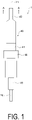
- FIG. 1 is a side view illustrating a configuration of a temperature sensor 1 according to an embodiment of the present invention
- FIG. 2 is a cross-sectional view illustrating the configuration of the temperature sensor 1.
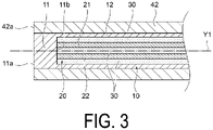
- FIG. 3 is a cross-sectional view illustrating a configuration of a tip portion of the temperature sensor
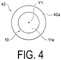
- FIG. 4 is an end view illustrating the configuration of the tip portion of the temperature sensor 1.
- FIG. 5 is a cross-sectional view illustrating the configuration of the tip portion of the temperature sensor 1 taken along an A-A line.
- the temperature sensor 1 is a temperature sensor for measuring the temperature of a resin 120 ( FIG. 6 ) filling a die 110 ( FIG. 6 ) and/or a fixed-side die 112 ( FIG. 6 ) in a resin molding device 100 ( FIG. 6 ) (i.e., any one or both of at least a surface temperature of the resin 120 and a die temperature near the temperature sensor 1).
- the temperature sensor 1 includes a metal sheath 10 having a bottomed tubular shape, a pair of thermocouple element wires 20 accommodated in the metal sheath 10, and an insulator 30 provided around the pair of thermocouple element wires 20 in the metal sheath 10, and the temperature sensor 1 is a grounded sheath thermocouple including a tip as a temperature measuring contact for the resin 120. Further, the temperature sensor 1 further includes a housing 40 covering a periphery of a tip portion of the metal sheath 10, and a tip of the metal sheath 10 has a planar shape.
- a temperature measurement system includes the temperature sensor 1 and a temperature measurement unit 140 configured to measure a temperature of the resin 120 filling the die 110 by the temperature sensor 1.
- a configuration of the temperature sensor 1 and the temperature measurement system will be specifically described below.
- the temperature sensor 1 has an outer shape extending in parallel or substantially parallel with a direction of an axis line Y1 with the axis line Y1 as the center, and being formed in a columnar rod shape or a substantially columnar rod shape.
- the grounded sheath thermocouple including the metal sheath 10, the pair of thermocouple element wires 20, and the insulator 30 is accommodated in the housing 40, and a portion at another end side is exposed from the housing 40.
- the metal sheath 10 extends in parallel or substantially parallel with the direction of the axis line Y1 with the axis line Y1 as the center, and is formed in a bottomed cylindrical shape or a substantially bottomed cylindrical shape.
- the metal sheath 10 includes a columnar portion 11 having a columnar shape or a substantially columnar shape, and a cylindrical portion 12 provided upright from another end side surface 11b of the columnar portion 11 and having a cylindrical shape or a substantially cylindrical shape.
- the columnar portion 11 functions as a temperature sensing portion configured to detect a temperature of the die 110 ( FIG. 6 ) around the tip portion of the temperature sensor 1 and the resin 120 ( FIG. 6 ).
- One end side surface 11a of the columnar portion 11 is the tip of the temperature sensor 1, and is the temperature measuring contact for the resin 120 ( FIG. 6 ).
- the one end side surface 11a of the columnar portion 11 is a circular or substantially circular plane extending orthogonally or substantially orthogonally to the direction of the axis line Y1 with the axis line Y1 as the center.
- the metal sheath 10 is formed of, for example, stainless steel, but other various metals can be used.
- the pair of thermocouple element wires 20 each extend at a predetermined interval in parallel or substantially parallel with the direction of the axis line Y1 in the metal sheath 10, and are each formed in a thin line shape or a substantially thin line shape.
- One thermocouple element wire of the pair of thermocouple element wires 20 is a thermocouple element wire 21 formed of, for example, a platinum-rhodium alloy
- the other thermocouple element wire of the pair of thermocouple element wires 20 is a thermocouple element wire 22 formed of, for example, platinum or a platinum-rhodium alloy.
- thermocouple element wires 21 and 22 has one end side welded to the other end side surface 11b of the columnar portion 11 of the metal sheath 10, and has another end side connected to a cable 130 ( FIG. 6 ) formed of a compensation lead wire (not illustrated).
- each of the thermocouple element wires 21 and 22 can be formed of, for example, alumel and chromel, and other various metals used as a thermocouple can be used.
- the insulator 30 fills the metal sheath 10 so as to cover a periphery of each of the thermocouple element wires 21 and 22, and insulates and holds the thermocouple element wires 21 and 22.
- the insulator 30 is formed of, for example, magnesia powder (MgO), but other various insulators can be used.
- the housing 40 extends in parallel or substantially parallel with the direction of the axis line Y1 with the axis line Y1 as the center, and includes a tubular portion 41 formed in a cylindrical shape or a substantially cylindrical shape.
- the tubular portion 41 includes a tip portion 42 at one end side, a crimp portion 43 at another end side, and a flange portion 44 at a center portion in the direction of the axis line Y1.
- the housing 40 is formed of, for example, stainless steel harder than the metal sheath 10, but other various metals different from the metal sheath 10 can be used.
- the tip portion 42 extends in parallel or substantially parallel with the direction of the axis line Y1 with the axis line Y1 as the center, and is formed in a cylindrical shape or a substantially cylindrical shape.
- the tip portion 42 is coaxial with the tubular portion 41, and communicates with the tubular portion 41.
- the diameter at one end side of the tubular portion 41 is reduced, and the diameter of the tip portion 42 is smaller than that of the tubular portion 41.
- the diameter of a tip of the tip portion 42 is, for example, equal to or less than 1 mm. Note that the diameter of the tip portion 42 may be greater than 1 mm.
- An inner diameter of the tip portion 42 is slightly smaller than a diameter of the metal sheath 10, and the tip portion of the metal sheath 10 is tightly fitted (press-fitted) into the tip portion 42.
- the tip portion 42 covers a portion of the columnar portion 11 and the cylindrical portion 12 of the metal sheath 10.
- a tip side surface 42a of the tip portion 42 is an annular or substantially annular plane extending orthogonally or substantially orthogonally to the direction of the axis line Y1 with the axis line Y1 as the center.
- the tip side surface 42a of the tip portion 42 is flush with the one end side surface 11a of the columnar portion 11 of the metal sheath 10.
- the tip side surface 42a of the tip portion 42 and the one end side surface 11a of the columnar portion 11 of the metal sheath 10 are welded together, and thus the tip portion 42 and the metal sheath 10 can be fixed together without a gap.
- the tip portion of the temperature sensor 1 is formed of the tip portion 42 and the grounded sheath thermocouple (the metal sheath 10, the pair of thermocouple element wires 20, and the insulator 30) accommodated in the tip portion 42, and the tip of the temperature sensor 1 is formed of the tip side surface 42a of the tip portion 42 and the one end side surface 11a of the columnar portion 11 of the metal sheath 10.
- the crimp portion 43 extends in parallel or substantially parallel with the direction of the axis line Y1 with the axis line Y1 as the center, and is formed in a cylindrical shape or a substantially cylindrical shape.
- the crimp portion 43 is coaxial with the tubular portion 41, and communicates with the tubular portion 41.
- the diameter of the crimp portion 43 is smaller than that of the tubular portion 41, and the crimp portion 43 fixes the metal sheath 10 to the housing 40 by crimping a portion of the metal sheath 10.
- the flange portion 44 is an annular or substantially annular flange extending from a circumferential surface of the tubular portion 41 toward a circumferential side at the center portion of the tubular portion 41 in the direction of the axis line Y1.
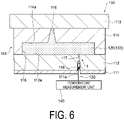
- FIGS. 6 and 7 are cross-sectional views illustrating the state where the temperature sensor 1 according to the embodiment of the present invention is attached to the die 110 of the resin molding device 100.
- the die 110 of the resin molding device 100 includes a fixed-side mounting plate 111, the fixed-side die 112, a movable-side mounting plate 113, and a movable-side die 114.
- the fixed-side die 112 is attached to the fixed-side mounting plate 111
- the movable-side die 114 is attached to the movable-side mounting plate 113.
- a recess portion 114a having a cross-sectional rectangular shape or a substantially cross-sectional rectangular shape is formed at the movable-side die 114, and a cavity 115 is formed by the movable-side die 114 and the fixed-side die 112. Further, a gate 116 for filling the cavity 115 with the resin 120 is formed at the recess portion 114a of the movable-side die 114.
- a mounting plate through hole 111a (or a wiring groove) is formed at the fixed-side mounting plate 111, a die through hole 117 is formed at the fixed-side die 112, and the mounting plate through hole 111a and the die through hole 117 communicate with each other.
- the temperature sensor 1 is inserted and fixed into the die through hole 117 of the fixed-side die 112.
- the die through hole 117 includes a tip portion fixing hole 117a, a tubular portion fixing hole 117b, and another end side through hole 117c.
- the tip portion fixing hole 117a is formed in a shape corresponding to the tip portion 42 of the housing 40, and is a hole slightly smaller than the diameter of the tip portion 42 of the housing 40, and the tip portion 42 is tightly fitted (press-fitted) into the tip portion fixing hole 117a.
- the tubular portion fixing hole 117b is a hole larger than the tip portion fixing hole 117a.
- the tubular portion fixing hole 117b is formed in a shape corresponding to the tubular portion 41 closer to a tip portion side than the flange portion 44.
- the tubular portion fixing hole 117b is a hole slightly smaller than the diameter of the tubular portion 41 closer to the tip portion side than the flange portion 44, and the tubular portion 41 closer to the tip portion side than the flange portion 44 is tightly fitted (press-fitted) into the tubular portion fixing hole 117b.
- the other end side through hole 117c is a hole larger than the tubular portion fixing hole 117b, and a step surface 117d is formed between the other end side through hole 117c and the tubular portion fixing hole 117b.
- the other end side through hole 117c is a hole having the same or substantially the same diameter as that of the flange portion 44, and includes a fixing spacer 118.
- the fixing spacer 118 is, for example, a cylindrical or substantially cylindrical pipe, has an outer diameter slightly larger than that of the other end side through hole 117c, and is press-fitted into the other end side through hole 117c.
- the fixing spacer 118 has an inner diameter slightly smaller than that of the center portion of the tubular portion 41 closer to the other end side than the flange portion 44, and fixes, into the other end side through hole 117c, the tubular portion 41 closer to the other end side than the flange portion 44.
- the tip of the temperature sensor 1 is flush with a cavity side surface 112a of the fixed-side die 112.
- the tip portion 42 of the housing 40 of the temperature sensor 1 is fixed by the tip portion fixing hole 117a, and the tubular portion 41 closer to the tip portion side than the flange portion 44 of the housing 40 of the temperature sensor 1 is fixed by the tubular portion fixing hole 117b.
- the tubular portion 41 closer to the other end side than the flange portion 44 of the housing 40 of the temperature sensor 1 is fixed by the fixing spacer 118 in the other end side through hole 117c.
- the flange portion 44 of the housing 40 of the temperature sensor 1 abuts against the step surface 117d between the other end side through hole 117c and the tubular portion fixing hole 117b, and the temperature sensor 1 is aligned by the step surface 117d. In this way, in the resin molding device 100, the tip of the temperature sensor 1 and the cavity side surface 112a of the fixed-side die 112 are located at the same plane.
- thermocouple element wires 21 and 22 of the temperature sensor 1 are connected to the cable 130 formed of the compensation lead wire (not illustrated) at the other end side, and the temperature sensor 1 is connected to the temperature measurement unit 140 via the cable 130.
- a plurality of the cavities 115 may be formed between the fixed-side die 112 and the movable-side die 114, the temperature sensor 1 corresponding to the individual cavity 115 may be provided, and the plurality of temperature sensors 1 may be connected to the temperature measurement unit 140. Further, the plurality of temperature sensors 1 may be provided in one cavity 115.
- the movable-side die 114 is moved, the movable-side die 114 abuts against the fixed-side die 112, and the cavity is filled with the resin 120 melted via the gate 116. Then, the resin molding device 100 molds a resin molded product 150 by cooling and hardening the resin 120 filling the cavity. Subsequently, in the resin molding device 100, the movable-side die 114 is moved, the movable-side die 114 is separated from the fixed-side die 112, the resin molded product 150 is ejected by an ejector pin (not illustrated), and the resin molded product 150 is taken out from the movable-side die 114.
- the temperature measurement unit 140 measures, via the cable 130, the current flowing through the thermocouple element wires 21 and 22 of the temperature sensor 1, and measures a temperature of the resin 120 based on the measured current. Further, the temperature measurement unit 140 also measures the temperature of the resin 120 based on the measured current until the resin 120 filling the cavity is cooled and hardened, and the resin molded product 150 is separated from the measuring contact of the temperature sensor 1.
- the temperature sensor 1 is a temperature sensor configured to measure the temperature of the resin 120 filling the die 110 (and/or the fixed-side die 112) in the resin molding device 100.
- the temperature sensor 1 includes the metal sheath 10 having a bottomed tubular shape, the pair of thermocouple element wires 20 accommodated in the metal sheath 10, and the insulator 30 provided around the pair of thermocouple element wires 20 in the metal sheath 10, and the temperature sensor 1 is the grounded sheath thermocouple including a tip as the temperature measuring contact of the resin 120. Further, the temperature sensor 1 further includes the housing 40 covering the periphery of the tip portion of the metal sheath 10, and the tip of the metal sheath 10 has a planar shape.
- the temperature sensor 1 at least a portion of the metal sheath 10 is crimped to the housing 40. Since the temperature sensor 1 is the grounded sheath thermocouple, two holes for guiding thermocouple element wires do not need to be processed and the thermocouple element wires also do not need to be assembled into the two holes as is the case with a temperature sensor conventionally used in the resin molding device 100. Therefore, in the temperature sensor 1, processability and assemblability of the temperature sensor 1 when the temperature sensor 1 is used in the resin molding device 100 can be improved.
- the periphery of the tip portion of the metal sheath 10 is covered by the housing 40, breakage of the metal sheath 10 of the temperature sensor 1 when the temperature sensor 1 is fixed to the movable-side die 114 can be prevented, and the assemblability when the temperature sensor 1 is fixed to the movable-side die 114 can be improved.
- the tip of the metal sheath 10 has a planar shape, a portion abutting the resin molded product 150 molded in the resin molding device 100 can be formed into a planar shape, and thus defects in the resin molded product 150 can be reduced.
- at least a portion of the metal sheath 10 is crimped to the housing 40, and thus the metal sheath 10 can be firmly fixed to the housing 40.
- the diameter of the tip of the tip portion 42 can be, for example, equal to or less than 1 mm, and the size of the temperature sensor 1 can be reduced. Further, in the temperature sensor 1, since the tip side surface 42a of the tip portion 42 is flush with the one end side surface 11a of the columnar portion 11 of the metal sheath 10, a portion abutting against the resin molded product 150 molded in the resin molding device 100 can be formed into a planar shape, and a defect in the resin molded product 150 can be further reduced.
- the tip side surface 42a of the tip portion 42 and the one end side surface 11a of the columnar portion 11 of the metal sheath 10 are welded together, the tip portion 42 and the metal sheath 10 can be fixed together without a gap.
- the resin molding device 100 constitutes the temperature measurement system consisting of the temperature sensor 1 attached to the die 110 and the temperature measurement unit 140 configured to measure the temperature of the resin 120 filling the die 110 by the temperature sensor 1.
- the temperature measurement unit 140 of the temperature measurement system measures, via the cable 130, the current flowing through the thermocouple element wires 21 and 22 of the temperature sensor 1, and measures the temperature of the resin 120 based on the measured current.
- the temperature measurement unit 140 can measure the temperature of the resin 120 by various methods.
- the embodiment of the present invention describes, as one example, a case where the temperature sensor 1 according to the embodiment of the present invention further includes the housing 40 covering the periphery of the tip portion of the metal sheath 10, the tip of the metal sheath 10 has a planar shape, and at least a portion of the metal sheath 10 is crimped to the housing 40.
- the present invention is not limited to the embodiment, and when the temperature sensor 1 is used in the resin molding device 100, the temperature sensor 1 may be formed of the grounded sheath thermocouple.
- the housing 40 need not cover the periphery of the tip portion of the metal sheath 10, and the metal sheath 10 may be fixed to the die through hole 117 of the movable-side die 114.
- the tip of the metal sheath 10 need not have a planar shape, and may have a shape such that the tip of the temperature sensor 1 and the cavity side surface 112a of the fixed-side die 112 are located at the same plane.
- the tip of the temperature sensor 1 including the tip of the metal sheath 10 may have a curved shape along the cavity side surface 112a of the fixed-side die 112. Further, in the temperature sensor 1, at least a portion of the metal sheath 10 need not be crimped to the housing 40, and at least a portion of the metal sheath 10 may be fixed to the housing 40.
Landscapes
- Physics & Mathematics (AREA)
- General Physics & Mathematics (AREA)
- Engineering & Computer Science (AREA)
- Manufacturing & Machinery (AREA)
- Mechanical Engineering (AREA)
- Moulds For Moulding Plastics Or The Like (AREA)
- Measuring Temperature Or Quantity Of Heat (AREA)
Abstract
Description
- The present invention relates to a temperature sensor and a temperature measurement system.
- Conventionally, a temperature sensor for measuring a temperature of a resin filling a die of a resin molding device has been widely known. As such a temperature sensor, for example, a temperature sensor being formed with two holes for guiding two thermocouple element wires to a tip of the temperature sensor and being formed by guiding the thermocouple element wires into the two holes, welding the thermocouple element wires to the temperature sensor, and then processing the tip of the temperature sensor has been proposed (for example, see Patent Document 1).
- Patent Document 1:
US 7,789,559 - In such a conventional temperature sensor, two holes for guiding two thermocouple element wires need to be processed. Herein, due to a reduction in size of the temperature sensor, the thermocouple element wires are also thinned, and thus there is a risk that it may become difficult to process the holes, and it may also become difficult to assemble the two thermocouple element wires into the two holes. Consequently, the conventional temperature sensor has been required to have a structure capable of improving processability and assemblability.
- The present invention has been made in view of the problem described above, and an object of the present invention is to provide a temperature sensor and a temperature measurement system capable of improving processability and assemblability.
- In order to achieve the object described above, a temperature sensor according to the present invention is a temperature sensor configured to measure a temperature of a resin filling a die in a resin molding device, the temperature sensor including: a metal sheath having a bottomed tubular shape; a pair of thermocouple element wires accommodated in the metal sheath; and an insulator provided around the pair of thermocouple element wires in the metal sheath, wherein the temperature sensor is a grounded sheath thermocouple including a tip as a temperature measuring contact for the resin, the temperature sensor further includes a housing covering a periphery of a tip portion of the metal sheath, and a tip of the metal sheath has a planar shape.
- In the temperature sensor according to one aspect of the present invention, a diameter of a tip of the housing is equal to or less than 1 mm.
- In the temperature sensor according to one aspect of the present invention, the tip of the metal sheath and the tip of the housing are flush.
- In the temperature sensor according to one aspect of the present invention, at least a portion of the metal sheath is crimped to the housing.
- In order to achieve the object described above, a temperature measurement system according to the present invention includes: in a resin molding device, the temperature sensor described above; and a temperature measurement unit configured to measure a temperature of a resin filling a die by the temperature sensor.
- A temperature sensor and a temperature measurement system according to the present invention can improve processability and assemblability.
-
-
FIG. 1 is a side view illustrating a configuration of a temperature sensor according to an embodiment of the present invention. -
FIG. 2 is a cross-sectional view illustrating the configuration of the temperature sensor illustrated inFIG. 1 . -
FIG. 3 is a cross-sectional view illustrating a configuration of a tip portion of the temperature sensor illustrated inFIG. 1 . -
FIG. 4 is an end view illustrating the configuration of the tip portion of the temperature sensor illustrated inFIG. 1 . -
FIG. 5 is a cross-sectional view illustrating the configuration of the tip portion of the temperature sensor illustrated inFIG. 1 taken along an A-A line. -
FIG. 6 is a cross-sectional view illustrating a state where the temperature sensor according to the embodiment of the present invention is attached to a die of a resin molding device. -
FIG. 7 is a cross-sectional view illustrating the state where the temperature sensor according to the embodiment of the present invention is attached to the die of the resin molding device. - An embodiment of the present invention will be described below with reference to the drawings.
-
FIG. 1 is a side view illustrating a configuration of atemperature sensor 1 according to an embodiment of the present invention, andFIG. 2 is a cross-sectional view illustrating the configuration of thetemperature sensor 1.FIG. 3 is a cross-sectional view illustrating a configuration of a tip portion of the temperature sensor, andFIG. 4 is an end view illustrating the configuration of the tip portion of thetemperature sensor 1.FIG. 5 is a cross-sectional view illustrating the configuration of the tip portion of thetemperature sensor 1 taken along an A-A line. - The
temperature sensor 1 according to the embodiment of the present invention is a temperature sensor for measuring the temperature of a resin 120 (FIG. 6 ) filling a die 110 (FIG. 6 ) and/or a fixed-side die 112 (FIG. 6 ) in a resin molding device 100 (FIG. 6 ) (i.e., any one or both of at least a surface temperature of theresin 120 and a die temperature near the temperature sensor 1). Thetemperature sensor 1 includes ametal sheath 10 having a bottomed tubular shape, a pair ofthermocouple element wires 20 accommodated in themetal sheath 10, and aninsulator 30 provided around the pair ofthermocouple element wires 20 in themetal sheath 10, and thetemperature sensor 1 is a grounded sheath thermocouple including a tip as a temperature measuring contact for theresin 120. Further, thetemperature sensor 1 further includes ahousing 40 covering a periphery of a tip portion of themetal sheath 10, and a tip of themetal sheath 10 has a planar shape. Further, in theresin molding device 100, a temperature measurement system according to the embodiment of the present invention includes thetemperature sensor 1 and atemperature measurement unit 140 configured to measure a temperature of theresin 120 filling thedie 110 by thetemperature sensor 1. A configuration of thetemperature sensor 1 and the temperature measurement system will be specifically described below. - As illustrated in
FIGS. 1 to 5 , thetemperature sensor 1 has an outer shape extending in parallel or substantially parallel with a direction of an axis line Y1 with the axis line Y1 as the center, and being formed in a columnar rod shape or a substantially columnar rod shape. As illustrated inFIG. 2 , in thetemperature sensor 1, the grounded sheath thermocouple including themetal sheath 10, the pair ofthermocouple element wires 20, and theinsulator 30 is accommodated in thehousing 40, and a portion at another end side is exposed from thehousing 40. - As illustrated in
FIGS. 3 to 5 , themetal sheath 10 extends in parallel or substantially parallel with the direction of the axis line Y1 with the axis line Y1 as the center, and is formed in a bottomed cylindrical shape or a substantially bottomed cylindrical shape. Themetal sheath 10 includes acolumnar portion 11 having a columnar shape or a substantially columnar shape, and acylindrical portion 12 provided upright from anotherend side surface 11b of thecolumnar portion 11 and having a cylindrical shape or a substantially cylindrical shape. Thecolumnar portion 11 functions as a temperature sensing portion configured to detect a temperature of the die 110 (FIG. 6 ) around the tip portion of thetemperature sensor 1 and the resin 120 (FIG. 6 ). - One
end side surface 11a of thecolumnar portion 11 is the tip of thetemperature sensor 1, and is the temperature measuring contact for the resin 120 (FIG. 6 ). The oneend side surface 11a of thecolumnar portion 11 is a circular or substantially circular plane extending orthogonally or substantially orthogonally to the direction of the axis line Y1 with the axis line Y1 as the center. Themetal sheath 10 is formed of, for example, stainless steel, but other various metals can be used. - The pair of
thermocouple element wires 20 each extend at a predetermined interval in parallel or substantially parallel with the direction of the axis line Y1 in themetal sheath 10, and are each formed in a thin line shape or a substantially thin line shape. One thermocouple element wire of the pair ofthermocouple element wires 20 is athermocouple element wire 21 formed of, for example, a platinum-rhodium alloy, and the other thermocouple element wire of the pair ofthermocouple element wires 20 is athermocouple element wire 22 formed of, for example, platinum or a platinum-rhodium alloy. - Each of the
thermocouple element wires end side surface 11b of thecolumnar portion 11 of themetal sheath 10, and has another end side connected to a cable 130 (FIG. 6 ) formed of a compensation lead wire (not illustrated). Note that each of thethermocouple element wires - The
insulator 30 fills themetal sheath 10 so as to cover a periphery of each of thethermocouple element wires thermocouple element wires insulator 30 is formed of, for example, magnesia powder (MgO), but other various insulators can be used. - The
housing 40 extends in parallel or substantially parallel with the direction of the axis line Y1 with the axis line Y1 as the center, and includes atubular portion 41 formed in a cylindrical shape or a substantially cylindrical shape. Thetubular portion 41 includes atip portion 42 at one end side, acrimp portion 43 at another end side, and aflange portion 44 at a center portion in the direction of the axis line Y1. Thehousing 40 is formed of, for example, stainless steel harder than themetal sheath 10, but other various metals different from themetal sheath 10 can be used. - The
tip portion 42 extends in parallel or substantially parallel with the direction of the axis line Y1 with the axis line Y1 as the center, and is formed in a cylindrical shape or a substantially cylindrical shape. Thetip portion 42 is coaxial with thetubular portion 41, and communicates with thetubular portion 41. The diameter at one end side of thetubular portion 41 is reduced, and the diameter of thetip portion 42 is smaller than that of thetubular portion 41. The diameter of a tip of thetip portion 42 is, for example, equal to or less than 1 mm. Note that the diameter of thetip portion 42 may be greater than 1 mm. - An inner diameter of the
tip portion 42 is slightly smaller than a diameter of themetal sheath 10, and the tip portion of themetal sheath 10 is tightly fitted (press-fitted) into thetip portion 42. In other words, thetip portion 42 covers a portion of thecolumnar portion 11 and thecylindrical portion 12 of themetal sheath 10. Atip side surface 42a of thetip portion 42 is an annular or substantially annular plane extending orthogonally or substantially orthogonally to the direction of the axis line Y1 with the axis line Y1 as the center. - The
tip side surface 42a of thetip portion 42 is flush with the oneend side surface 11a of thecolumnar portion 11 of themetal sheath 10. Thetip side surface 42a of thetip portion 42 and the oneend side surface 11a of thecolumnar portion 11 of themetal sheath 10 are welded together, and thus thetip portion 42 and themetal sheath 10 can be fixed together without a gap. The tip portion of thetemperature sensor 1 is formed of thetip portion 42 and the grounded sheath thermocouple (themetal sheath 10, the pair ofthermocouple element wires 20, and the insulator 30) accommodated in thetip portion 42, and the tip of thetemperature sensor 1 is formed of thetip side surface 42a of thetip portion 42 and the oneend side surface 11a of thecolumnar portion 11 of themetal sheath 10. - The
crimp portion 43 extends in parallel or substantially parallel with the direction of the axis line Y1 with the axis line Y1 as the center, and is formed in a cylindrical shape or a substantially cylindrical shape. Thecrimp portion 43 is coaxial with thetubular portion 41, and communicates with thetubular portion 41. The diameter of thecrimp portion 43 is smaller than that of thetubular portion 41, and thecrimp portion 43 fixes themetal sheath 10 to thehousing 40 by crimping a portion of themetal sheath 10. Theflange portion 44 is an annular or substantially annular flange extending from a circumferential surface of thetubular portion 41 toward a circumferential side at the center portion of thetubular portion 41 in the direction of the axis line Y1. - Next, a state where the
temperature sensor 1 is attached to the die 110 of theresin molding device 100 will be described.FIGS. 6 and7 are cross-sectional views illustrating the state where thetemperature sensor 1 according to the embodiment of the present invention is attached to the die 110 of theresin molding device 100. The die 110 of theresin molding device 100 includes a fixed-side mounting plate 111, the fixed-side die 112, a movable-side mounting plate 113, and a movable-side die 114. In thedie 110, the fixed-side die 112 is attached to the fixed-side mounting plate 111, and the movable-side die 114 is attached to the movable-side mounting plate 113. - For example, a
recess portion 114a having a cross-sectional rectangular shape or a substantially cross-sectional rectangular shape is formed at the movable-side die 114, and acavity 115 is formed by the movable-side die 114 and the fixed-side die 112. Further, agate 116 for filling thecavity 115 with theresin 120 is formed at therecess portion 114a of the movable-side die 114. - A mounting plate through
hole 111a (or a wiring groove) is formed at the fixed-side mounting plate 111, a die throughhole 117 is formed at the fixed-side die 112, and the mounting plate throughhole 111a and the die throughhole 117 communicate with each other. Thetemperature sensor 1 is inserted and fixed into the die throughhole 117 of the fixed-side die 112. The die throughhole 117 includes a tipportion fixing hole 117a, a tubularportion fixing hole 117b, and another end side throughhole 117c. - The tip
portion fixing hole 117a is formed in a shape corresponding to thetip portion 42 of thehousing 40, and is a hole slightly smaller than the diameter of thetip portion 42 of thehousing 40, and thetip portion 42 is tightly fitted (press-fitted) into the tipportion fixing hole 117a. The tubularportion fixing hole 117b is a hole larger than the tipportion fixing hole 117a. The tubularportion fixing hole 117b is formed in a shape corresponding to thetubular portion 41 closer to a tip portion side than theflange portion 44. The tubularportion fixing hole 117b is a hole slightly smaller than the diameter of thetubular portion 41 closer to the tip portion side than theflange portion 44, and thetubular portion 41 closer to the tip portion side than theflange portion 44 is tightly fitted (press-fitted) into the tubularportion fixing hole 117b. - The other end side through
hole 117c is a hole larger than the tubularportion fixing hole 117b, and astep surface 117d is formed between the other end side throughhole 117c and the tubularportion fixing hole 117b. The other end side throughhole 117c is a hole having the same or substantially the same diameter as that of theflange portion 44, and includes a fixingspacer 118. The fixingspacer 118 is, for example, a cylindrical or substantially cylindrical pipe, has an outer diameter slightly larger than that of the other end side throughhole 117c, and is press-fitted into the other end side throughhole 117c. Further, the fixingspacer 118 has an inner diameter slightly smaller than that of the center portion of thetubular portion 41 closer to the other end side than theflange portion 44, and fixes, into the other end side throughhole 117c, thetubular portion 41 closer to the other end side than theflange portion 44. - The tip of the
temperature sensor 1 is flush with acavity side surface 112a of the fixed-side die 112. Thetip portion 42 of thehousing 40 of thetemperature sensor 1 is fixed by the tipportion fixing hole 117a, and thetubular portion 41 closer to the tip portion side than theflange portion 44 of thehousing 40 of thetemperature sensor 1 is fixed by the tubularportion fixing hole 117b. Thetubular portion 41 closer to the other end side than theflange portion 44 of thehousing 40 of thetemperature sensor 1 is fixed by the fixingspacer 118 in the other end side throughhole 117c. - The
flange portion 44 of thehousing 40 of thetemperature sensor 1 abuts against thestep surface 117d between the other end side throughhole 117c and the tubularportion fixing hole 117b, and thetemperature sensor 1 is aligned by thestep surface 117d. In this way, in theresin molding device 100, the tip of thetemperature sensor 1 and thecavity side surface 112a of the fixed-side die 112 are located at the same plane. - The
thermocouple element wires temperature sensor 1 are connected to thecable 130 formed of the compensation lead wire (not illustrated) at the other end side, and thetemperature sensor 1 is connected to thetemperature measurement unit 140 via thecable 130. Note that, in thedie 110, a plurality of thecavities 115 may be formed between the fixed-side die 112 and the movable-side die 114, thetemperature sensor 1 corresponding to theindividual cavity 115 may be provided, and the plurality oftemperature sensors 1 may be connected to thetemperature measurement unit 140. Further, the plurality oftemperature sensors 1 may be provided in onecavity 115. - During resin molding, in the
resin molding device 100, the movable-side die 114 is moved, the movable-side die 114 abuts against the fixed-side die 112, and the cavity is filled with theresin 120 melted via thegate 116. Then, theresin molding device 100 molds a resin moldedproduct 150 by cooling and hardening theresin 120 filling the cavity. Subsequently, in theresin molding device 100, the movable-side die 114 is moved, the movable-side die 114 is separated from the fixed-side die 112, the resin moldedproduct 150 is ejected by an ejector pin (not illustrated), and the resin moldedproduct 150 is taken out from the movable-side die 114. - Herein, when the cavity is filled with the melted
resin 120, the meltedresin 120 abuts against the temperature measuring contact of the tip of thetemperature sensor 1, the temperature of the temperature measuring contact of thetemperature sensor 1 increases, and a temperature difference is caused between the temperature measuring contact of thetemperature sensor 1 and a reference contact. Consequently, a voltage is generated in thethermocouple element wires temperature sensor 1, and a minute current flows through thethermocouple element wires temperature measurement unit 140 measures, via thecable 130, the current flowing through thethermocouple element wires temperature sensor 1, and measures a temperature of theresin 120 based on the measured current. Further, thetemperature measurement unit 140 also measures the temperature of theresin 120 based on the measured current until theresin 120 filling the cavity is cooled and hardened, and the resin moldedproduct 150 is separated from the measuring contact of thetemperature sensor 1. - In this way, the
temperature sensor 1 according to the embodiment of the present invention is a temperature sensor configured to measure the temperature of theresin 120 filling the die 110 (and/or the fixed-side die 112) in theresin molding device 100. Thetemperature sensor 1 includes themetal sheath 10 having a bottomed tubular shape, the pair ofthermocouple element wires 20 accommodated in themetal sheath 10, and theinsulator 30 provided around the pair ofthermocouple element wires 20 in themetal sheath 10, and thetemperature sensor 1 is the grounded sheath thermocouple including a tip as the temperature measuring contact of theresin 120. Further, thetemperature sensor 1 further includes thehousing 40 covering the periphery of the tip portion of themetal sheath 10, and the tip of themetal sheath 10 has a planar shape. Further, in thetemperature sensor 1, at least a portion of themetal sheath 10 is crimped to thehousing 40. Since thetemperature sensor 1 is the grounded sheath thermocouple, two holes for guiding thermocouple element wires do not need to be processed and the thermocouple element wires also do not need to be assembled into the two holes as is the case with a temperature sensor conventionally used in theresin molding device 100. Therefore, in thetemperature sensor 1, processability and assemblability of thetemperature sensor 1 when thetemperature sensor 1 is used in theresin molding device 100 can be improved. - Further, since the periphery of the tip portion of the
metal sheath 10 is covered by thehousing 40, breakage of themetal sheath 10 of thetemperature sensor 1 when thetemperature sensor 1 is fixed to the movable-side die 114 can be prevented, and the assemblability when thetemperature sensor 1 is fixed to the movable-side die 114 can be improved. Further, since the tip of themetal sheath 10 has a planar shape, a portion abutting the resin moldedproduct 150 molded in theresin molding device 100 can be formed into a planar shape, and thus defects in the resin moldedproduct 150 can be reduced. Further, at least a portion of themetal sheath 10 is crimped to thehousing 40, and thus themetal sheath 10 can be firmly fixed to thehousing 40. - Further, in the
temperature sensor 1, since the two holes for guiding the thermocouple element wires do not need to be processed and the thermocouple element wires also do not need to be assembled into the two holes, and the processability and assemblability of thetemperature sensor 1 can be improved, the diameter of the tip of thetip portion 42 can be, for example, equal to or less than 1 mm, and the size of thetemperature sensor 1 can be reduced. Further, in thetemperature sensor 1, since thetip side surface 42a of thetip portion 42 is flush with the oneend side surface 11a of thecolumnar portion 11 of themetal sheath 10, a portion abutting against the resin moldedproduct 150 molded in theresin molding device 100 can be formed into a planar shape, and a defect in the resin moldedproduct 150 can be further reduced. Further, in thetemperature sensor 1, since thetip side surface 42a of thetip portion 42 and the oneend side surface 11a of thecolumnar portion 11 of themetal sheath 10 are welded together, thetip portion 42 and themetal sheath 10 can be fixed together without a gap. - Further, the
resin molding device 100 constitutes the temperature measurement system consisting of thetemperature sensor 1 attached to the die 110 and thetemperature measurement unit 140 configured to measure the temperature of theresin 120 filling thedie 110 by thetemperature sensor 1. Thetemperature measurement unit 140 of the temperature measurement system measures, via thecable 130, the current flowing through thethermocouple element wires temperature sensor 1, and measures the temperature of theresin 120 based on the measured current. Note that thetemperature measurement unit 140 can measure the temperature of theresin 120 by various methods. - The embodiment of the present invention has been described above; however, the present invention is not limited to the embodiment of the present invention described above, and includes various aspects included in concepts and claims of the present invention. Further, each of the configurations may be selectively combined as appropriate so as to achieve at least a part of the problem and the effect described above. For example, a shape, a material, an arrangement, a size, and the like of each of the components in the embodiment described above may be changed as appropriate according to a specific usage aspect of the present invention.
- For example, the embodiment of the present invention describes, as one example, a case where the
temperature sensor 1 according to the embodiment of the present invention further includes thehousing 40 covering the periphery of the tip portion of themetal sheath 10, the tip of themetal sheath 10 has a planar shape, and at least a portion of themetal sheath 10 is crimped to thehousing 40. However, the present invention is not limited to the embodiment, and when thetemperature sensor 1 is used in theresin molding device 100, thetemperature sensor 1 may be formed of the grounded sheath thermocouple. - In other words, in the
temperature sensor 1 according to the embodiment of the present invention, thehousing 40 need not cover the periphery of the tip portion of themetal sheath 10, and themetal sheath 10 may be fixed to the die throughhole 117 of the movable-side die 114. Further, in thetemperature sensor 1, the tip of themetal sheath 10 need not have a planar shape, and may have a shape such that the tip of thetemperature sensor 1 and thecavity side surface 112a of the fixed-side die 112 are located at the same plane. For example, when thecavity side surface 112a of the fixed-side die 112 has a curved shape, the tip of thetemperature sensor 1 including the tip of themetal sheath 10 may have a curved shape along thecavity side surface 112a of the fixed-side die 112. Further, in thetemperature sensor 1, at least a portion of themetal sheath 10 need not be crimped to thehousing 40, and at least a portion of themetal sheath 10 may be fixed to thehousing 40. -
- 1 Temperature sensor
- 10 Metal sheath
- 20 Pair of thermocouple element wires
- 30 Insulator
- 40 Housing
- 100 Resin molding device
- 110 Die
- 120 Resin
Claims (5)
- A temperature sensor configured to measure a temperature of a resin filling a die in a resin molding device, the temperature sensor comprising:a metal sheath having a bottomed tubular shape;a pair of thermocouple element wires accommodated in the metal sheath; andan insulator provided around the pair of thermocouple element wires in the metal sheath, whereinthe temperature sensor is a grounded sheath thermocouple including a tip as a temperature measuring contact for the resin,the temperature sensor further includes a housing covering a periphery of a tip portion of the metal sheath, anda tip of the metal sheath has a planar shape.
- The temperature sensor according to claim 1, wherein
a diameter of a tip of the housing is equal to or less than 1 mm. - The temperature sensor according to claim 1 or 2, wherein
the tip of the metal sheath and the tip of the housing are flush. - The temperature sensor according to any one of claims 1 to 3, wherein
at least a portion of the metal sheath is crimped to the housing. - A temperature measurement system, comprising:in a resin molding device,the temperature sensor according to any one of claims 1 to 4; anda temperature measurement unit configured to measure a temperature of a resin filling a die by the temperature sensor.
Applications Claiming Priority (2)
| Application Number | Priority Date | Filing Date | Title |
|---|---|---|---|
| JP2019118909A JP7424763B2 (en) | 2019-06-26 | 2019-06-26 | Temperature sensors and temperature measurement systems |
| PCT/JP2020/016657 WO2020261722A1 (en) | 2019-06-26 | 2020-04-16 | Temperature sensor and temperature measurement system |
Publications (2)
| Publication Number | Publication Date |
|---|---|
| EP3992597A1 true EP3992597A1 (en) | 2022-05-04 |
| EP3992597A4 EP3992597A4 (en) | 2023-07-05 |
Family
ID=74060521
Family Applications (1)
| Application Number | Title | Priority Date | Filing Date |
|---|---|---|---|
| EP20831254.6A Pending EP3992597A4 (en) | 2019-06-26 | 2020-04-16 | Temperature sensor and temperature measurement system |
Country Status (5)
| Country | Link |
|---|---|
| US (1) | US12313475B2 (en) |
| EP (1) | EP3992597A4 (en) |
| JP (1) | JP7424763B2 (en) |
| CN (1) | CN114008423A (en) |
| WO (1) | WO2020261722A1 (en) |
Families Citing this family (2)
| Publication number | Priority date | Publication date | Assignee | Title |
|---|---|---|---|---|
| JP2024013942A (en) * | 2022-07-21 | 2024-02-01 | 双葉電子工業株式会社 | Measuring device manufacturing method and measuring device |
| WO2025147419A1 (en) * | 2024-01-04 | 2025-07-10 | Massachusetts Institute Of Technology | Co-wound coaxial voltage sensors for quench detection in grooved, stacked-plate, no-insulation superconducting coils |
Family Cites Families (14)
| Publication number | Priority date | Publication date | Assignee | Title |
|---|---|---|---|---|
| GB764837A (en) * | 1954-07-12 | 1957-01-02 | British Thomson Houston Co Ltd | Improvements in and relating to signal transmission systems using dynamo-electric transmitter and receiver devices |
| US4444990A (en) * | 1982-09-08 | 1984-04-24 | Servo Corporation Of America | Heat sensing device |
| AT386682B (en) * | 1984-03-29 | 1988-09-26 | Chemiefaser Lenzing Ag | HEATING ROLLER |
| JP2627454B2 (en) * | 1990-02-09 | 1997-07-09 | 株式会社名機製作所 | Screw temperature measuring device |
| FR2710409B1 (en) * | 1993-09-21 | 1995-12-15 | Crmt | Thermocouple-sensor and its manufacturing process. |
| EP0764837A1 (en) * | 1995-09-25 | 1997-03-26 | Isuzu Ceramics Research Institute Co., Ltd. | Thermocouple structure |
| JP4716611B2 (en) * | 2001-07-19 | 2011-07-06 | 川惣電機工業株式会社 | Temperature sensor holding device |
| JP2003080577A (en) * | 2001-09-07 | 2003-03-19 | Ishii Kikai Seisakusho:Kk | Temperature detecting terminal unit for mold for molding plastic and thermometer |
| DE10258100B4 (en) * | 2002-12-11 | 2005-12-01 | Priamus System Technologies Ag | Method for producing a device for measuring, monitoring and / or regulating a temperature |
| JP5018481B2 (en) * | 2005-09-28 | 2012-09-05 | コニカミノルタアドバンストレイヤー株式会社 | Injection molding equipment |
| EP1898195B1 (en) | 2006-09-06 | 2010-07-14 | Kistler Holding AG | Temperature sensor with processable front |
| JP5326826B2 (en) * | 2009-06-02 | 2013-10-30 | 三菱マテリアル株式会社 | Temperature sensor |
| JP5503717B1 (en) * | 2012-11-30 | 2014-05-28 | 双葉電子工業株式会社 | Temperature detector, temperature sensor, and method of manufacturing temperature detector |
| JP6711997B1 (en) * | 2019-04-25 | 2020-06-17 | 株式会社八洲測器 | Manufacturing method of mold temperature sensor |
-
2019
- 2019-06-26 JP JP2019118909A patent/JP7424763B2/en active Active
-
2020
- 2020-04-16 EP EP20831254.6A patent/EP3992597A4/en active Pending
- 2020-04-16 WO PCT/JP2020/016657 patent/WO2020261722A1/en not_active Ceased
- 2020-04-16 US US17/596,432 patent/US12313475B2/en active Active
- 2020-04-16 CN CN202080043720.XA patent/CN114008423A/en active Pending
Also Published As
| Publication number | Publication date |
|---|---|
| JP2021004804A (en) | 2021-01-14 |
| US12313475B2 (en) | 2025-05-27 |
| EP3992597A4 (en) | 2023-07-05 |
| JP7424763B2 (en) | 2024-01-30 |
| CN114008423A (en) | 2022-02-01 |
| WO2020261722A1 (en) | 2020-12-30 |
| US20220252463A1 (en) | 2022-08-11 |
Similar Documents
| Publication | Publication Date | Title |
|---|---|---|
| US4018624A (en) | Thermocouple structure and method of manufacturing same | |
| JP4620400B2 (en) | Temperature sensor and method of manufacturing temperature sensor | |
| US12313475B2 (en) | Temperature sensor and temperature measurement system | |
| US9816879B2 (en) | Temperature sensor | |
| CN103364095B (en) | Plug-in temperature sensor | |
| GB2556170A (en) | Integrated pressure and temperature sensor | |
| JP2001503528A (en) | Pressure / temperature sensor | |
| US20120134388A1 (en) | Nail puncture test device having temperature measurement function | |
| US5685884A (en) | Method of making a transducer | |
| CN102419219A (en) | Temperature sensor | |
| EP3339825B1 (en) | High-temperature exhaust sensor | |
| US10139286B2 (en) | Junction assembly of electrical cables, and thermocouple sensor comprising such junction | |
| JP2014109462A (en) | Temperature detection body, temperature sensor, and method of manufacturing temperature detection body | |
| CN102265128A (en) | Temperature sensor, method of manufacture and corresponding method of assembly | |
| WO1997014022A1 (en) | Encapsulated transducer with sleeve and component alignment | |
| EP3382358B1 (en) | Temperature sensor | |
| CN107110712A (en) | Temperature sensor | |
| JP6711997B1 (en) | Manufacturing method of mold temperature sensor | |
| US10620057B2 (en) | Tubular wire shielding for an exhaust gas temperature sensor arrangement, exhaust gas temperature sensor arrangement and method for assembling an exhaust gas temperature sensor arrangement | |
| JPH11351977A (en) | Combined temperature and pressure sensor | |
| JP4755578B2 (en) | Element and insulating resin same-diameter platinum resistance thermometer and method for manufacturing the same | |
| JPH09210807A (en) | Device for measuring multi-point temperatures | |
| JP2017049191A (en) | Pin with pressure sensor and molding apparatus | |
| CN113227735A (en) | Temperature sensing device | |
| JP5101928B2 (en) | Sensor |
Legal Events
| Date | Code | Title | Description |
|---|---|---|---|
| STAA | Information on the status of an ep patent application or granted ep patent |
Free format text: STATUS: THE INTERNATIONAL PUBLICATION HAS BEEN MADE |
|
| PUAI | Public reference made under article 153(3) epc to a published international application that has entered the european phase |
Free format text: ORIGINAL CODE: 0009012 |
|
| STAA | Information on the status of an ep patent application or granted ep patent |
Free format text: STATUS: REQUEST FOR EXAMINATION WAS MADE |
|
| 17P | Request for examination filed |
Effective date: 20220106 |
|
| AK | Designated contracting states |
Kind code of ref document: A1 Designated state(s): AL AT BE BG CH CY CZ DE DK EE ES FI FR GB GR HR HU IE IS IT LI LT LU LV MC MK MT NL NO PL PT RO RS SE SI SK SM TR |
|
| DAV | Request for validation of the european patent (deleted) | ||
| DAX | Request for extension of the european patent (deleted) | ||
| A4 | Supplementary search report drawn up and despatched |
Effective date: 20230606 |
|
| RIC1 | Information provided on ipc code assigned before grant |
Ipc: B29C 45/00 20060101ALI20230601BHEP Ipc: G01K 7/06 20060101ALI20230601BHEP Ipc: G01K 1/14 20210101ALI20230601BHEP Ipc: B29C 33/00 20060101ALI20230601BHEP Ipc: G01K 1/08 20210101ALI20230601BHEP Ipc: G01K 7/02 20210101AFI20230601BHEP |
|
| P01 | Opt-out of the competence of the unified patent court (upc) registered |
Free format text: CASE NUMBER: APP_52604/2024 Effective date: 20240919 |
|
| STAA | Information on the status of an ep patent application or granted ep patent |
Free format text: STATUS: EXAMINATION IS IN PROGRESS |
|
| 17Q | First examination report despatched |
Effective date: 20241210 |
|
| REG | Reference to a national code |
Ref country code: DE Ref legal event code: R079 Free format text: PREVIOUS MAIN CLASS: G01K0007020000 Ipc: B29C0045780000 |
|
| GRAP | Despatch of communication of intention to grant a patent |
Free format text: ORIGINAL CODE: EPIDOSNIGR1 |
|
| STAA | Information on the status of an ep patent application or granted ep patent |
Free format text: STATUS: GRANT OF PATENT IS INTENDED |
|
| RIC1 | Information provided on ipc code assigned before grant |
Ipc: B29C 45/78 20060101AFI20260122BHEP Ipc: G01K 7/02 20210101ALI20260122BHEP Ipc: G01K 1/08 20210101ALI20260122BHEP Ipc: B29C 33/00 20060101ALI20260122BHEP Ipc: G01K 1/14 20210101ALI20260122BHEP Ipc: G01K 7/06 20060101ALI20260122BHEP Ipc: B29C 45/00 20060101ALI20260122BHEP |
|
| INTG | Intention to grant announced |
Effective date: 20260203 |